WO2014181614A1 - 自動二輪車用タイヤ - Google Patents
自動二輪車用タイヤ Download PDFInfo
- Publication number
- WO2014181614A1 WO2014181614A1 PCT/JP2014/059676 JP2014059676W WO2014181614A1 WO 2014181614 A1 WO2014181614 A1 WO 2014181614A1 JP 2014059676 W JP2014059676 W JP 2014059676W WO 2014181614 A1 WO2014181614 A1 WO 2014181614A1
- Authority
- WO
- WIPO (PCT)
- Prior art keywords
- tire
- groove
- inclined groove
- central inclined
- width direction
- Prior art date
Links
Images

Classifications
-
- B—PERFORMING OPERATIONS; TRANSPORTING
- B60—VEHICLES IN GENERAL
- B60C—VEHICLE TYRES; TYRE INFLATION; TYRE CHANGING; CONNECTING VALVES TO INFLATABLE ELASTIC BODIES IN GENERAL; DEVICES OR ARRANGEMENTS RELATED TO TYRES
- B60C11/00—Tyre tread bands; Tread patterns; Anti-skid inserts
- B60C11/03—Tread patterns
- B60C11/0327—Tread patterns characterised by special properties of the tread pattern
-
- B—PERFORMING OPERATIONS; TRANSPORTING
- B60—VEHICLES IN GENERAL
- B60C—VEHICLE TYRES; TYRE INFLATION; TYRE CHANGING; CONNECTING VALVES TO INFLATABLE ELASTIC BODIES IN GENERAL; DEVICES OR ARRANGEMENTS RELATED TO TYRES
- B60C11/00—Tyre tread bands; Tread patterns; Anti-skid inserts
- B60C11/03—Tread patterns
- B60C11/0302—Tread patterns directional pattern, i.e. with main rolling direction
-
- B—PERFORMING OPERATIONS; TRANSPORTING
- B60—VEHICLES IN GENERAL
- B60C—VEHICLE TYRES; TYRE INFLATION; TYRE CHANGING; CONNECTING VALVES TO INFLATABLE ELASTIC BODIES IN GENERAL; DEVICES OR ARRANGEMENTS RELATED TO TYRES
- B60C11/00—Tyre tread bands; Tread patterns; Anti-skid inserts
- B60C11/03—Tread patterns
- B60C11/032—Patterns comprising isolated recesses
-
- B—PERFORMING OPERATIONS; TRANSPORTING
- B60—VEHICLES IN GENERAL
- B60C—VEHICLE TYRES; TYRE INFLATION; TYRE CHANGING; CONNECTING VALVES TO INFLATABLE ELASTIC BODIES IN GENERAL; DEVICES OR ARRANGEMENTS RELATED TO TYRES
- B60C11/00—Tyre tread bands; Tread patterns; Anti-skid inserts
- B60C11/03—Tread patterns
- B60C11/13—Tread patterns characterised by the groove cross-section, e.g. for buttressing or preventing stone-trapping
- B60C11/1307—Tread patterns characterised by the groove cross-section, e.g. for buttressing or preventing stone-trapping with special features of the groove walls
- B60C11/1315—Tread patterns characterised by the groove cross-section, e.g. for buttressing or preventing stone-trapping with special features of the groove walls having variable inclination angles, e.g. warped groove walls
-
- B—PERFORMING OPERATIONS; TRANSPORTING
- B60—VEHICLES IN GENERAL
- B60C—VEHICLE TYRES; TYRE INFLATION; TYRE CHANGING; CONNECTING VALVES TO INFLATABLE ELASTIC BODIES IN GENERAL; DEVICES OR ARRANGEMENTS RELATED TO TYRES
- B60C11/00—Tyre tread bands; Tread patterns; Anti-skid inserts
- B60C11/03—Tread patterns
- B60C11/13—Tread patterns characterised by the groove cross-section, e.g. for buttressing or preventing stone-trapping
- B60C11/1353—Tread patterns characterised by the groove cross-section, e.g. for buttressing or preventing stone-trapping with special features of the groove bottom
-
- B—PERFORMING OPERATIONS; TRANSPORTING
- B60—VEHICLES IN GENERAL
- B60C—VEHICLE TYRES; TYRE INFLATION; TYRE CHANGING; CONNECTING VALVES TO INFLATABLE ELASTIC BODIES IN GENERAL; DEVICES OR ARRANGEMENTS RELATED TO TYRES
- B60C11/00—Tyre tread bands; Tread patterns; Anti-skid inserts
- B60C11/03—Tread patterns
- B60C2011/0337—Tread patterns characterised by particular design features of the pattern
- B60C2011/0339—Grooves
- B60C2011/0374—Slant grooves, i.e. having an angle of about 5 to 35 degrees to the equatorial plane
- B60C2011/0379—Slant grooves, i.e. having an angle of about 5 to 35 degrees to the equatorial plane characterised by depth
-
- B—PERFORMING OPERATIONS; TRANSPORTING
- B60—VEHICLES IN GENERAL
- B60C—VEHICLE TYRES; TYRE INFLATION; TYRE CHANGING; CONNECTING VALVES TO INFLATABLE ELASTIC BODIES IN GENERAL; DEVICES OR ARRANGEMENTS RELATED TO TYRES
- B60C11/00—Tyre tread bands; Tread patterns; Anti-skid inserts
- B60C11/03—Tread patterns
- B60C2011/0337—Tread patterns characterised by particular design features of the pattern
- B60C2011/0339—Grooves
- B60C2011/0381—Blind or isolated grooves
-
- B—PERFORMING OPERATIONS; TRANSPORTING
- B60—VEHICLES IN GENERAL
- B60C—VEHICLE TYRES; TYRE INFLATION; TYRE CHANGING; CONNECTING VALVES TO INFLATABLE ELASTIC BODIES IN GENERAL; DEVICES OR ARRANGEMENTS RELATED TO TYRES
- B60C2200/00—Tyres specially adapted for particular applications
- B60C2200/10—Tyres specially adapted for particular applications for motorcycles, scooters or the like
Definitions
- the present invention relates to a motorcycle tire (hereinafter, also simply referred to as “tire”), and more particularly to an improvement in a tread pattern of a pneumatic radial tire for a motorcycle useful for a high-speed motorcycle suitable for circuit driving.
- motorcycle tires have a smaller curvature than that of automobile tires due to the characteristics of motorcycles that turn by tilting the vehicle body unlike automobiles and trucks. Has a round tire shape. For this reason, depending on the grounding state, there is a problem in that the sliding part becomes uneven in the grounding surface due to the position of the grounding part, particularly when a large driving force is applied, and uneven wear in which a specific part is abraded easily occurs. It was.
- Patent Document 1 As a conventional technique related to a motorcycle tire, for example, in Patent Document 1, a first groove extending in an inclined direction outward in the tread width direction toward a designated tire rotation direction on a tread surface, and an end portion in the reverse rotation direction are disclosed. A technique for disposing a bent main groove including a second groove extending obliquely in the reverse rotation direction toward the outer side in the tread width direction is disclosed.
- Patent Document 1 According to the tire disclosed in Patent Document 1, it is possible to achieve both grip performance and wet performance at a high level by improving drainage while suppressing a decrease in the contact area with respect to input from the road surface. In addition, there has been a demand for the realization of motorcycle tires with improved uneven wear resistance and high-speed running performance.
- an object of the present invention is to provide a tire for a motorcycle that solves the above-described problems and suppresses the occurrence of uneven wear, while improving drainage and steering stability performance at high speeds.
- the present inventor has found that the above problems can be solved by optimizing the angle and location of the grooves arranged on the tread surface, and has completed the present invention.
- the motorcycle tire of the present invention is a motorcycle tire in which the rotation direction when the vehicle is mounted is designated, In the vicinity of the tire equator surface of the tread surface, a central inclined groove extending incline from the tire equator surface side toward the tire width direction toward the reverse rotation direction of the specified rotation direction, An angle formed by the extending direction of the central inclined groove with respect to the tire circumferential direction is in a range of 3 ° to 10 °; At the end portion of the central inclined groove in the reverse rotation direction, an angle formed by at least the tire width direction outer groove edge of the central inclined groove with respect to the tire circumferential direction of the tire width direction outer groove edge faces the reverse rotation direction.
- An angle formed with the arcuate portion that increases and the angle of the central inclined groove with respect to the tire circumferential direction of the outer groove edge in the tire width direction is larger than the angle with respect to the tire circumferential direction of the inner groove edge in the tire width direction.
- the groove depth of the central inclined groove is gradually reduced toward the groove edge in the reverse rotation direction of the central inclined groove.
- the tire equator is directed toward the reverse rotation direction at a position that is on the outer side in the tire width direction from the end portion on the inner side in the tire width direction of the central inclined groove and does not overlap the central inclined groove in the tire circumferential direction.
- An outer inclined groove extending obliquely outward in the tire width direction from the surface side, and the angle formed with respect to the tire circumferential direction in the extending direction of the outer inclined groove is the tire circumference in the extending direction of the central inclined groove It is preferable that the angle is larger than the angle formed with respect to the direction.
- an inner end in the tire width direction of the outer inclined groove overlaps with the central inclined groove in the tire width direction, and a groove depth of the outer inclined groove is an end in the rotation direction. And gradually decreasing toward the groove edge in the rotational direction of the outer inclined groove, and in the tire circumferential direction of the inner groove edge in the tire width direction of the outer inclined groove at the end in the rotational direction of the outer inclined groove. It is preferable that the angle formed is larger than the angle formed with respect to the tire circumferential direction of the outer groove edge in the tire width direction.
- adjacent end portions of the central inclined groove and the outer inclined groove have groove edges parallel to each other.
- the groove depth of the central inclined groove gradually decreases toward the rotational edge of the central inclined groove at the end of the central inclined groove in the rotational direction.
- the angle formed by the central inclined groove with respect to the tire circumferential direction of the inner groove edge in the tire width direction is larger than the angle formed with respect to the tire circumferential direction of the outer groove edge in the tire width direction.
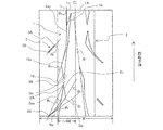
- FIG. 1 is a partial development view showing a tread of an example of a motorcycle tire of the present invention.
- FIG. 4A is a plan view showing a central inclined groove taken out
- FIG. 5B is a cross-sectional view taken along line XX in FIG.
- FIG. 1 is a partial development view showing a tread of an example of a motorcycle tire of the present invention.
- the motorcycle tire of the present invention has a so-called directional pattern in which the direction of rotation when the vehicle is mounted is designated.
- the arrow in FIG. 1 shows the rotation direction (designated rotation direction) at the time of vehicle mounting of the illustrated tire.
- the tire rotates in the reverse direction of the designated rotational direction, that is, in the direction opposite to the arrow in the figure, and from the tire equatorial plane CL side to the tire width direction.
- a central inclined groove 1 is provided extending in an inclined manner outward. Since the central inclined groove 1 is an inclined groove having no bent portion as shown in the drawing, there is no portion where stress is concentrated, and uneven wear does not occur.
- the angle ⁇ 1 formed with respect to the tire circumferential direction in the extending direction of the central inclined groove 1 is in the range of 3 ° to 10 °.
- the extending direction of the central inclined groove 1 is defined as a direction of a straight line connecting the outermost points 1A and 1B in the tire circumferential direction of the central inclined groove 1 as illustrated.
- the central inclined groove 1 is arranged at an angle close to the tire circumferential direction such that the angle ⁇ 1 formed with respect to the tire circumferential direction is 10 ° or less, so that the rigidity in the tire circumferential direction is increased. It can be kept high, and the occurrence of uneven wear during straight running can also be suppressed.
- the extending direction of the central inclined groove 1 is a direction along the tire input, it is possible to suppress the deformation that reduces the ground contact area even when the input is performed at a high speed. If the angle ⁇ 1 in the extending direction of the central inclined groove 1 is less than 3 °, drainage to the outside in the tire width direction is hindered, so that the drainage cannot be secured, and if it exceeds 10 °, the effect of suppressing the above-mentioned uneven wear, etc. Is not enough. Since drainage can be obtained by setting the angle ⁇ 1 to 3 ° or more, the angle ⁇ 1 needs to be in the range of 3 ° to 10 ° in order to achieve both drainage and uneven wear. is there.
- the central inclined groove 1 can be said to have a small angle with respect to the tire circumferential direction from the viewpoint of drainage
- the central inclined groove 1 At least a tire width direction outer side groove edge 1bo of the groove 1 is formed by an arcuate portion such that an angle formed with respect to the tire circumferential direction increases in the reverse rotation direction. Therefore, since the effect of draining toward the outer side in the tire width direction along the central inclined groove 1 is obtained by the arc-shaped portion, the drainage performance is not deteriorated.
- the arc-shaped portion means that an arc shape or a shape formed in an arc shape by connecting straight lines is included.
- FIG. 2A is a plan view showing the central inclined groove 1 taken out
- FIG. 2B is a cross-sectional view taken along the line XX along the center line in the width direction of the central inclined groove in FIG.
- the groove depth of the central inclined groove 1 is gradually reduced at the end portion in the reverse rotation direction, the decrease in rigidity in the tire circumferential direction at this portion is suppressed, and Abrasion can also be suppressed.
- an angle ⁇ 2 formed with respect to the tire circumferential direction of the tire width direction outer groove edge 1bo is formed larger than an angle ⁇ 1 formed with respect to the tire circumferential direction of the tire width direction inner groove edge 1bi.
- the angle ⁇ 2 of the central inclined groove 1 with respect to the tire circumferential direction of the tire width direction outer groove edge 1bo is the tire width direction outer groove edge passing through the outermost point in the reverse rotation direction of the tire width direction outer groove edge 1bo.
- the 1-bo tangent is defined as the angle formed with the tire circumferential direction.
- the groove width of the central inclined groove 1 is formed so as to spread toward the reverse rotation direction at the end in the reverse rotation direction, thereby maintaining good drainage. It is what. Therefore, in the tire according to the present invention, by arranging the central inclined groove 1 having the above-described configuration, it is possible to achieve both high speed running performance corresponding to circuit running, drainage, and uneven wear.
- the inner groove edge in the tire width direction of the central inclined groove 1 is substantially linear, and the outermost points 1A and 1B in the tire circumferential direction of the central inclined groove 1 are substantially in the tire width direction.
- the angle formed with respect to the tire circumferential direction of the tire width direction inner groove edge 1bi at the end in the reverse rotation direction is the tire circumferential direction of the extending direction of the central inclined groove 1
- the present invention is not limited to this.
- the inner groove edge of the central inclined groove 1 is not linear, for example, when it is curved, the central inclined This includes the case where the outermost points 1A, 1B in the tire circumferential direction of the groove 1 are not both end points of the inner groove edge in the tire width direction.
- the tire circumferential direction it is preferable to form by an arcuate portion in which the angle formed with respect to the angle increases in the reverse rotation direction. Thereby, drainage can be improved more.
- the groove depth of the central inclined groove 1 in the rotational direction is gradually decreased toward the groove edge 1c in the rotational direction of the central inclined groove 1, and the tire width direction of the central inclined groove 1 is also reduced.
- the angle ⁇ 1 formed with respect to the tire circumferential direction of the inner groove edge 1ai is preferably formed to be larger than the angle ⁇ 3 formed with respect to the tire circumferential direction of the outer width groove edge 1ao in the tire width direction. That is, as shown in the figure, in the present invention, the groove width of the central inclined groove 1 is formed so as to spread toward the rotation direction also at the end portion in the rotation direction.
- the end of the central inclined groove 1 near the tire equator plane in the rotational direction is the area where the input is the largest, such as during traction. It is preferable to increase the groove width in order to maintain drainage while suppressing uneven wear.
- the outer edge of the central inclined groove 1 in the tire width direction is formed in a curved shape that protrudes toward the tire equatorial plane, and this point can also contribute to maintaining high rigidity.
- the angle formed with respect to the tire circumferential direction of the tire width direction inner groove edge 1ai is substantially the same as the angle formed with respect to the tire circumferential direction in the extending direction of the central inclined groove 1.
- the present invention is not limited to this.
- the central inclined groove 1 does not cross the tire equatorial plane, that is, terminates in a tire one side region having a width of 1 ⁇ 2 of the tread surface. This is because rigidity is required most on the tire equatorial plane.
- the central inclined groove 1 is arranged in a region of 1 ⁇ 4 W from the tire equator plane when the peripheral length of the tread tread is W.
- the peripheral length of the tread tread is the same as the tread tread when the tire is assembled to the applicable rim specified by the following standard and the maximum air pressure specified by the tire size is filled according to the standard. The length measured in the tire width direction.
- the standard is determined by an industrial standard effective in the region where the tire is produced or used. For example, in Japan, it is defined by JATMA YEAR BOOK of the Japan Automobile Tire Association, and in the United States it is TRA (THE TIRE and RIM ASSOCIATION INC.). It is specified by YEAR BOOK and in Europe, it is specified by STANDARD MANUAL of ETRTO (European Tire and Rim Technical Organization).
- the input in the tire width direction (lateral direction) is the main, but the central inclined groove 1 arranged in the direction close to the tire circumferential direction is for the lateral input. This is because the rigidity is weak, and if the central inclined groove 1 is arranged in this outer region, it may cause uneven wear.
- the length of the central inclined groove 1 in the tire circumferential direction is preferably in the range of 8% to 15% of the total tire circumferential length. If the length of the central inclined groove 1 in the tire circumferential direction is too short, it is difficult to ensure sufficient drainage, and if it is too long, the steering stability may be lowered due to a decrease in rigidity, which is not preferable.
- the central inclined groove 1 is located on the outer side in the tire width direction from the inner end of the central inclined groove 1 in the tire width direction and overlaps with the central inclined groove 1 in the tire circumferential direction.
- An outer inclined groove 2 that extends in an inclined direction from the tire equatorial plane side toward the tire width direction is disposed at a position where it does not become necessary.
- An angle ⁇ 4 formed with respect to the tire circumferential direction in the extending direction of the outer inclined groove 2 is larger than an angle ⁇ 1 formed with respect to the tire circumferential direction in the extending direction of the central inclined groove 1.
- the extending direction of the outer inclined groove 2 is defined as the direction of a straight line connecting the outermost points 2A and 2B in the tire circumferential direction of the outer inclined groove 2 as shown in the figure.
- the outer inclined groove 2 having a larger angle with respect to the tire circumferential direction than the central inclined groove 1 on the outer side in the tire width direction from the central inclined groove 1, drainage can be further improved.
- the outer inclined groove 2 is disposed at a position overlapping the central inclined groove 1 in the tire circumferential direction, the rigidity is locally lowered and the uneven wear property is deteriorated.
- the central inclined groove 1 is offset in the tire circumferential direction. Thereby, drainage can be improved more without deteriorating uneven wear.
- the outer inclined groove 2 is arranged so that the inner end in the tire width direction overlaps the central inclined groove 1 in the tire width direction, and the groove depth of the outer inclined groove 2 is the rotational direction. Is gradually reduced toward the groove edge 2c in the rotation direction of the outer inclined groove 2.
- an angle ⁇ 5 formed with respect to the tire circumferential direction of the tire width direction inner groove edge 2ai at the end portion in the rotation direction of the outer inclined groove 2 is larger than an angle ⁇ 6 formed with respect to the tire circumferential direction of the tire width direction outer groove edge 2ao.
- the angle ⁇ 7 formed with respect to the tire circumferential direction of the tire width direction inner groove edge 2bi is preferably in the range of 45 ° to 55 °. By setting it as this angle, drainage property and partial wear property can be made compatible.
- the adjacent end portions of the central inclined groove 1 and the outer inclined groove 2 are preferably provided with mutually parallel groove edges. That is, the groove edge 1d in the reverse rotation direction of the central inclined groove 1 and the groove edge 2c in the rotation direction of the outer inclined groove 2 are preferably formed in parallel to each other.
- the ground contact region is changed from the formation portion of the central inclined groove 1 to the formation portion of the outer inclined groove 2 during cornering.
- the outer narrow groove 3 is disposed at a position overlapping the central inclined groove 1 in the tire circumferential direction and outside the central inclined groove 1 in the tire width direction.
- the outer narrow groove 3 has a narrower groove width than the groove width measured in the direction perpendicular to the groove extending direction of the central inclined groove 1 that overlaps the outer narrow groove 3 in the tire circumferential direction. ing. If there is only the outer inclined groove 2 in the region on the outer side in the tire width direction from the central inclined groove 1, the rigidity step is increased in the tire circumferential direction, and therefore, between the arrangement positions of the outer inclined grooves 2 in the tire circumferential direction.
- the rigidity in the tire circumferential direction is made uniform, and the occurrence of uneven wear in the region outside the central inclined groove 1 in the tire width direction is suppressed. be able to.
- the angle ⁇ 8 formed in the extending direction of the outer narrow groove 3 with respect to the tire circumferential direction is preferably in the range of 45 ° to 55 °.
- the extending direction of the outer fine groove 3 is defined as the direction of a straight line connecting the outermost points 3A and 3B in the tire circumferential direction of the outer fine groove 3 as shown in the figure. By setting it as this angle, drainage property and partial wear property can be made compatible.
- the outer narrow groove 3 is preferably disposed within a region of 1/4 W from the end portion in the tire width direction of the tread surface with respect to the peripheral length W of the tread surface.
- the arrangement pitch of the central inclined groove 1, the outer inclined groove 2, and the outer fine groove 3 is not particularly limited, but should be, for example, about 1/6 to 1/10 of the entire circumference of the tire. Can do. Further, the tire circumferential direction positions of the central inclined groove 1, the outer inclined groove 2, and the outer fine groove 3 in the present invention are alternately shifted by 1/2 of the arrangement pitch on both sides of the tread surface sandwiching the tire equatorial plane CL. Has been.
- the tire of the present invention includes a tread portion that forms a tread surface portion, and a pair of sidewall portions and bead portions that are continuous on both sides thereof, and usually straddles between bead cores embedded in the pair of bead portions, respectively. It has a carcass arranged to reinforce each part, and one or more belts arranged outside the crown part tire in the radial direction to reinforce the tread part.
- the present invention is useful as a rear tire for a motorcycle.
- a tire size of 180 / 55ZR17 is provided with a pair of bead portions and sidewall portions, and a tread portion extending in a toroidal shape between both sidewall portions, and the rotational direction when the vehicle is mounted
- the groove depth of the central inclined groove is gradually decreased toward the groove edge in the rotation direction at the end in the rotation direction
- the groove depth of the outer inclination groove is also the end in the rotation direction. In the part, it gradually decreased toward the groove edge in the rotation direction.
- test tires were attached to a motorcycle, and the test course was run at a speed of 130 km / h, and it was confirmed whether or not uneven wear occurred during the 3000 km run and the 6000 km run.
- rider's feelings through actual vehicle tests, each of the running performance on a wet road and the high speed steering stability performance at a speed of 150 km / h on a dry road is evaluated. It showed in. A numerical value shows that it is so favorable that all are high.
- results are also shown in the following table.
Landscapes
- Engineering & Computer Science (AREA)
- Mechanical Engineering (AREA)
- Tires In General (AREA)
Priority Applications (2)
| Application Number | Priority Date | Filing Date | Title |
|---|---|---|---|
| US14/787,547 US10358000B2 (en) | 2013-05-09 | 2014-04-01 | Tire for two-wheeled motor vehicle |
| EP14795525.6A EP2995473B1 (de) | 2013-05-09 | 2014-04-01 | Reifen für ein zweirädriges kraftfahrzeug |
Applications Claiming Priority (2)
| Application Number | Priority Date | Filing Date | Title |
|---|---|---|---|
| JP2013099489A JP5517319B1 (ja) | 2013-05-09 | 2013-05-09 | 自動二輪車用タイヤ |
| JP2013-099489 | 2013-05-09 |
Publications (1)
| Publication Number | Publication Date |
|---|---|
| WO2014181614A1 true WO2014181614A1 (ja) | 2014-11-13 |
Family
ID=51031255
Family Applications (1)
| Application Number | Title | Priority Date | Filing Date |
|---|---|---|---|
| PCT/JP2014/059676 WO2014181614A1 (ja) | 2013-05-09 | 2014-04-01 | 自動二輪車用タイヤ |
Country Status (4)
| Country | Link |
|---|---|
| US (1) | US10358000B2 (de) |
| EP (1) | EP2995473B1 (de) |
| JP (1) | JP5517319B1 (de) |
| WO (1) | WO2014181614A1 (de) |
Cited By (3)
| Publication number | Priority date | Publication date | Assignee | Title |
|---|---|---|---|---|
| JP2021049837A (ja) * | 2019-09-24 | 2021-04-01 | 株式会社ブリヂストン | 自動二輪車用タイヤ |
| WO2021060033A1 (ja) * | 2019-09-24 | 2021-04-01 | 株式会社ブリヂストン | 自動二輪車用タイヤ |
| JP2021049836A (ja) * | 2019-09-24 | 2021-04-01 | 株式会社ブリヂストン | 自動二輪車用タイヤ |
Families Citing this family (2)
| Publication number | Priority date | Publication date | Assignee | Title |
|---|---|---|---|---|
| FR3062343A1 (fr) * | 2017-01-27 | 2018-08-03 | Compagnie Generale Des Etablissements Michelin | Pneumatique a bande de roulement optimisee |
| JP7310174B2 (ja) | 2019-03-05 | 2023-07-19 | 住友ゴム工業株式会社 | タイヤ |
Citations (9)
| Publication number | Priority date | Publication date | Assignee | Title |
|---|---|---|---|---|
| JPS62118704U (de) * | 1986-01-21 | 1987-07-28 | ||
| JP1339331S (en) * | 2007-03-09 | 2008-09-08 | The tire for motor bicycles | |
| JP1393392S (en) * | 2009-06-22 | 2010-07-26 | The tire for motor bicycles | |
| JP2011189805A (ja) | 2010-03-12 | 2011-09-29 | Bridgestone Corp | 自動二輪車用空気入りタイヤ |
| WO2012001907A1 (ja) * | 2010-07-02 | 2012-01-05 | 株式会社ブリヂストン | 空気入りタイヤ |
| JP1435352S (en) * | 2010-08-10 | 2012-03-05 | The tire for motor bicycles | |
| JP2012206669A (ja) * | 2011-03-30 | 2012-10-25 | Bridgestone Corp | 自動二輪車用タイヤ |
| JP2012236478A (ja) * | 2011-05-11 | 2012-12-06 | Sumitomo Rubber Ind Ltd | 空気入りタイヤ |
| JP2013159208A (ja) * | 2012-02-03 | 2013-08-19 | Sumitomo Rubber Ind Ltd | 自動二輪車用タイヤ |
Family Cites Families (5)
| Publication number | Priority date | Publication date | Assignee | Title |
|---|---|---|---|---|
| JPS6064004A (ja) * | 1983-09-20 | 1985-04-12 | Bridgestone Corp | 接地性にすぐれた不整地走行用タイヤ |
| JPH05201207A (ja) * | 1992-01-27 | 1993-08-10 | Bridgestone Corp | モーターサイクル用空気入りタイヤ |
| BR112012001376B1 (pt) | 2009-07-28 | 2020-11-24 | Pirelli Tyre S.P.A | pneu para motocicleta |
| WO2011041859A1 (en) * | 2009-10-07 | 2011-04-14 | Pirelli Tyre S.P.A. | Motorcycle tyres |
| EP2554403A1 (de) | 2010-03-26 | 2013-02-06 | Bridgestone Corporation | Luftreifen für ein motorrad |
-
2013
- 2013-05-09 JP JP2013099489A patent/JP5517319B1/ja not_active Expired - Fee Related
-
2014
- 2014-04-01 US US14/787,547 patent/US10358000B2/en active Active
- 2014-04-01 EP EP14795525.6A patent/EP2995473B1/de not_active Not-in-force
- 2014-04-01 WO PCT/JP2014/059676 patent/WO2014181614A1/ja active Application Filing
Patent Citations (9)
| Publication number | Priority date | Publication date | Assignee | Title |
|---|---|---|---|---|
| JPS62118704U (de) * | 1986-01-21 | 1987-07-28 | ||
| JP1339331S (en) * | 2007-03-09 | 2008-09-08 | The tire for motor bicycles | |
| JP1393392S (en) * | 2009-06-22 | 2010-07-26 | The tire for motor bicycles | |
| JP2011189805A (ja) | 2010-03-12 | 2011-09-29 | Bridgestone Corp | 自動二輪車用空気入りタイヤ |
| WO2012001907A1 (ja) * | 2010-07-02 | 2012-01-05 | 株式会社ブリヂストン | 空気入りタイヤ |
| JP1435352S (en) * | 2010-08-10 | 2012-03-05 | The tire for motor bicycles | |
| JP2012206669A (ja) * | 2011-03-30 | 2012-10-25 | Bridgestone Corp | 自動二輪車用タイヤ |
| JP2012236478A (ja) * | 2011-05-11 | 2012-12-06 | Sumitomo Rubber Ind Ltd | 空気入りタイヤ |
| JP2013159208A (ja) * | 2012-02-03 | 2013-08-19 | Sumitomo Rubber Ind Ltd | 自動二輪車用タイヤ |
Non-Patent Citations (1)
| Title |
|---|
| See also references of EP2995473A4 |
Cited By (5)
| Publication number | Priority date | Publication date | Assignee | Title |
|---|---|---|---|---|
| JP2021049837A (ja) * | 2019-09-24 | 2021-04-01 | 株式会社ブリヂストン | 自動二輪車用タイヤ |
| WO2021060033A1 (ja) * | 2019-09-24 | 2021-04-01 | 株式会社ブリヂストン | 自動二輪車用タイヤ |
| JP2021049836A (ja) * | 2019-09-24 | 2021-04-01 | 株式会社ブリヂストン | 自動二輪車用タイヤ |
| JP7183134B2 (ja) | 2019-09-24 | 2022-12-05 | 株式会社ブリヂストン | 自動二輪車用タイヤ |
| JP7227882B2 (ja) | 2019-09-24 | 2023-02-22 | 株式会社ブリヂストン | 自動二輪車用タイヤ |
Also Published As
| Publication number | Publication date |
|---|---|
| EP2995473A4 (de) | 2016-04-13 |
| JP5517319B1 (ja) | 2014-06-11 |
| EP2995473B1 (de) | 2017-06-07 |
| EP2995473A1 (de) | 2016-03-16 |
| US10358000B2 (en) | 2019-07-23 |
| JP2014218194A (ja) | 2014-11-20 |
| US20160075187A1 (en) | 2016-03-17 |
Similar Documents
| Publication | Publication Date | Title |
|---|---|---|
| JP4973708B2 (ja) | 空気入りタイヤ | |
| JP2003211917A (ja) | 二輪車用空気入りタイヤ | |
| JP5973942B2 (ja) | 空気入りタイヤ | |
| WO2014181614A1 (ja) | 自動二輪車用タイヤ | |
| JP7310174B2 (ja) | タイヤ | |
| JP5596580B2 (ja) | 自動二輪車用空気入りタイヤ | |
| JP7251219B2 (ja) | タイヤ | |
| CN105835628B (zh) | 摩托车用充气轮胎 | |
| JP2012162160A (ja) | 自動二輪車用空気入りタイヤ | |
| JP5048345B2 (ja) | 二輪車用空気入りタイヤ | |
| WO2013121946A1 (ja) | 自動二輪車用空気入りタイヤ | |
| WO2013084436A1 (ja) | 自動二輪車用空気入りタイヤ | |
| TWI486266B (zh) | 自動二輪車用輪胎 | |
| JP2011088498A (ja) | タイヤ | |
| JP5890192B2 (ja) | 自動二輪車用空気入りタイヤ | |
| JP2007076594A (ja) | 空気入りタイヤ | |
| JP6506061B2 (ja) | 自動二輪車用タイヤ | |
| JP5945207B2 (ja) | 自動二輪車用タイヤ | |
| JP6060217B2 (ja) | 自動二輪車用空気入りタイヤ | |
| JP5724279B2 (ja) | 空気入りタイヤ | |
| WO2019203067A1 (ja) | 空気入りタイヤ | |
| WO2019203066A1 (ja) | 空気入りタイヤ | |
| JP5626954B2 (ja) | タイヤ | |
| JP5992177B2 (ja) | 自動二輪車用空気入りタイヤ |
Legal Events
| Date | Code | Title | Description |
|---|---|---|---|
| 121 | Ep: the epo has been informed by wipo that ep was designated in this application |
Ref document number: 14795525 Country of ref document: EP Kind code of ref document: A1 |
|
| WWE | Wipo information: entry into national phase |
Ref document number: 14787547 Country of ref document: US |
|
| NENP | Non-entry into the national phase |
Ref country code: DE |
|
| REEP | Request for entry into the european phase |
Ref document number: 2014795525 Country of ref document: EP |
|
| WWE | Wipo information: entry into national phase |
Ref document number: 2014795525 Country of ref document: EP |