WO2014181614A1 - 自動二輪車用タイヤ - Google Patents
自動二輪車用タイヤ Download PDFInfo
- Publication number
- WO2014181614A1 WO2014181614A1 PCT/JP2014/059676 JP2014059676W WO2014181614A1 WO 2014181614 A1 WO2014181614 A1 WO 2014181614A1 JP 2014059676 W JP2014059676 W JP 2014059676W WO 2014181614 A1 WO2014181614 A1 WO 2014181614A1
- Authority
- WO
- WIPO (PCT)
- Prior art keywords
- tire
- groove
- inclined groove
- central inclined
- width direction
- Prior art date
Links
Images

Classifications
-
- B—PERFORMING OPERATIONS; TRANSPORTING
- B60—VEHICLES IN GENERAL
- B60C—VEHICLE TYRES; TYRE INFLATION; TYRE CHANGING; CONNECTING VALVES TO INFLATABLE ELASTIC BODIES IN GENERAL; DEVICES OR ARRANGEMENTS RELATED TO TYRES
- B60C11/00—Tyre tread bands; Tread patterns; Anti-skid inserts
- B60C11/03—Tread patterns
- B60C11/0327—Tread patterns characterised by special properties of the tread pattern
-
- B—PERFORMING OPERATIONS; TRANSPORTING
- B60—VEHICLES IN GENERAL
- B60C—VEHICLE TYRES; TYRE INFLATION; TYRE CHANGING; CONNECTING VALVES TO INFLATABLE ELASTIC BODIES IN GENERAL; DEVICES OR ARRANGEMENTS RELATED TO TYRES
- B60C11/00—Tyre tread bands; Tread patterns; Anti-skid inserts
- B60C11/03—Tread patterns
- B60C11/0302—Tread patterns directional pattern, i.e. with main rolling direction
-
- B—PERFORMING OPERATIONS; TRANSPORTING
- B60—VEHICLES IN GENERAL
- B60C—VEHICLE TYRES; TYRE INFLATION; TYRE CHANGING; CONNECTING VALVES TO INFLATABLE ELASTIC BODIES IN GENERAL; DEVICES OR ARRANGEMENTS RELATED TO TYRES
- B60C11/00—Tyre tread bands; Tread patterns; Anti-skid inserts
- B60C11/03—Tread patterns
- B60C11/032—Patterns comprising isolated recesses
-
- B—PERFORMING OPERATIONS; TRANSPORTING
- B60—VEHICLES IN GENERAL
- B60C—VEHICLE TYRES; TYRE INFLATION; TYRE CHANGING; CONNECTING VALVES TO INFLATABLE ELASTIC BODIES IN GENERAL; DEVICES OR ARRANGEMENTS RELATED TO TYRES
- B60C11/00—Tyre tread bands; Tread patterns; Anti-skid inserts
- B60C11/03—Tread patterns
- B60C11/13—Tread patterns characterised by the groove cross-section, e.g. for buttressing or preventing stone-trapping
- B60C11/1307—Tread patterns characterised by the groove cross-section, e.g. for buttressing or preventing stone-trapping with special features of the groove walls
- B60C11/1315—Tread patterns characterised by the groove cross-section, e.g. for buttressing or preventing stone-trapping with special features of the groove walls having variable inclination angles, e.g. warped groove walls
-
- B—PERFORMING OPERATIONS; TRANSPORTING
- B60—VEHICLES IN GENERAL
- B60C—VEHICLE TYRES; TYRE INFLATION; TYRE CHANGING; CONNECTING VALVES TO INFLATABLE ELASTIC BODIES IN GENERAL; DEVICES OR ARRANGEMENTS RELATED TO TYRES
- B60C11/00—Tyre tread bands; Tread patterns; Anti-skid inserts
- B60C11/03—Tread patterns
- B60C11/13—Tread patterns characterised by the groove cross-section, e.g. for buttressing or preventing stone-trapping
- B60C11/1353—Tread patterns characterised by the groove cross-section, e.g. for buttressing or preventing stone-trapping with special features of the groove bottom
-
- B—PERFORMING OPERATIONS; TRANSPORTING
- B60—VEHICLES IN GENERAL
- B60C—VEHICLE TYRES; TYRE INFLATION; TYRE CHANGING; CONNECTING VALVES TO INFLATABLE ELASTIC BODIES IN GENERAL; DEVICES OR ARRANGEMENTS RELATED TO TYRES
- B60C11/00—Tyre tread bands; Tread patterns; Anti-skid inserts
- B60C11/03—Tread patterns
- B60C2011/0337—Tread patterns characterised by particular design features of the pattern
- B60C2011/0339—Grooves
- B60C2011/0374—Slant grooves, i.e. having an angle of about 5 to 35 degrees to the equatorial plane
- B60C2011/0379—Slant grooves, i.e. having an angle of about 5 to 35 degrees to the equatorial plane characterised by depth
-
- B—PERFORMING OPERATIONS; TRANSPORTING
- B60—VEHICLES IN GENERAL
- B60C—VEHICLE TYRES; TYRE INFLATION; TYRE CHANGING; CONNECTING VALVES TO INFLATABLE ELASTIC BODIES IN GENERAL; DEVICES OR ARRANGEMENTS RELATED TO TYRES
- B60C11/00—Tyre tread bands; Tread patterns; Anti-skid inserts
- B60C11/03—Tread patterns
- B60C2011/0337—Tread patterns characterised by particular design features of the pattern
- B60C2011/0339—Grooves
- B60C2011/0381—Blind or isolated grooves
-
- B—PERFORMING OPERATIONS; TRANSPORTING
- B60—VEHICLES IN GENERAL
- B60C—VEHICLE TYRES; TYRE INFLATION; TYRE CHANGING; CONNECTING VALVES TO INFLATABLE ELASTIC BODIES IN GENERAL; DEVICES OR ARRANGEMENTS RELATED TO TYRES
- B60C2200/00—Tyres specially adapted for particular applications
- B60C2200/10—Tyres specially adapted for particular applications for motorcycles, scooters or the like
Definitions
- the present invention relates to a motorcycle tire (hereinafter, also simply referred to as “tire”), and more particularly to an improvement in a tread pattern of a pneumatic radial tire for a motorcycle useful for a high-speed motorcycle suitable for circuit driving.
- motorcycle tires have a smaller curvature than that of automobile tires due to the characteristics of motorcycles that turn by tilting the vehicle body unlike automobiles and trucks. Has a round tire shape. For this reason, depending on the grounding state, there is a problem in that the sliding part becomes uneven in the grounding surface due to the position of the grounding part, particularly when a large driving force is applied, and uneven wear in which a specific part is abraded easily occurs. It was.
- Patent Document 1 As a conventional technique related to a motorcycle tire, for example, in Patent Document 1, a first groove extending in an inclined direction outward in the tread width direction toward a designated tire rotation direction on a tread surface, and an end portion in the reverse rotation direction are disclosed. A technique for disposing a bent main groove including a second groove extending obliquely in the reverse rotation direction toward the outer side in the tread width direction is disclosed.
- Patent Document 1 According to the tire disclosed in Patent Document 1, it is possible to achieve both grip performance and wet performance at a high level by improving drainage while suppressing a decrease in the contact area with respect to input from the road surface. In addition, there has been a demand for the realization of motorcycle tires with improved uneven wear resistance and high-speed running performance.
- an object of the present invention is to provide a tire for a motorcycle that solves the above-described problems and suppresses the occurrence of uneven wear, while improving drainage and steering stability performance at high speeds.
- the present inventor has found that the above problems can be solved by optimizing the angle and location of the grooves arranged on the tread surface, and has completed the present invention.
- the motorcycle tire of the present invention is a motorcycle tire in which the rotation direction when the vehicle is mounted is designated, In the vicinity of the tire equator surface of the tread surface, a central inclined groove extending incline from the tire equator surface side toward the tire width direction toward the reverse rotation direction of the specified rotation direction, An angle formed by the extending direction of the central inclined groove with respect to the tire circumferential direction is in a range of 3 ° to 10 °; At the end portion of the central inclined groove in the reverse rotation direction, an angle formed by at least the tire width direction outer groove edge of the central inclined groove with respect to the tire circumferential direction of the tire width direction outer groove edge faces the reverse rotation direction.
- An angle formed with the arcuate portion that increases and the angle of the central inclined groove with respect to the tire circumferential direction of the outer groove edge in the tire width direction is larger than the angle with respect to the tire circumferential direction of the inner groove edge in the tire width direction.
- the groove depth of the central inclined groove is gradually reduced toward the groove edge in the reverse rotation direction of the central inclined groove.
- the tire equator is directed toward the reverse rotation direction at a position that is on the outer side in the tire width direction from the end portion on the inner side in the tire width direction of the central inclined groove and does not overlap the central inclined groove in the tire circumferential direction.
- An outer inclined groove extending obliquely outward in the tire width direction from the surface side, and the angle formed with respect to the tire circumferential direction in the extending direction of the outer inclined groove is the tire circumference in the extending direction of the central inclined groove It is preferable that the angle is larger than the angle formed with respect to the direction.
- an inner end in the tire width direction of the outer inclined groove overlaps with the central inclined groove in the tire width direction, and a groove depth of the outer inclined groove is an end in the rotation direction. And gradually decreasing toward the groove edge in the rotational direction of the outer inclined groove, and in the tire circumferential direction of the inner groove edge in the tire width direction of the outer inclined groove at the end in the rotational direction of the outer inclined groove. It is preferable that the angle formed is larger than the angle formed with respect to the tire circumferential direction of the outer groove edge in the tire width direction.
- adjacent end portions of the central inclined groove and the outer inclined groove have groove edges parallel to each other.
- the groove depth of the central inclined groove gradually decreases toward the rotational edge of the central inclined groove at the end of the central inclined groove in the rotational direction.
- the angle formed by the central inclined groove with respect to the tire circumferential direction of the inner groove edge in the tire width direction is larger than the angle formed with respect to the tire circumferential direction of the outer groove edge in the tire width direction.
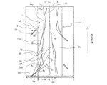
- FIG. 1 is a partial development view showing a tread of an example of a motorcycle tire of the present invention.
- FIG. 4A is a plan view showing a central inclined groove taken out
- FIG. 5B is a cross-sectional view taken along line XX in FIG.
- FIG. 1 is a partial development view showing a tread of an example of a motorcycle tire of the present invention.
- the motorcycle tire of the present invention has a so-called directional pattern in which the direction of rotation when the vehicle is mounted is designated.
- the arrow in FIG. 1 shows the rotation direction (designated rotation direction) at the time of vehicle mounting of the illustrated tire.
- the tire rotates in the reverse direction of the designated rotational direction, that is, in the direction opposite to the arrow in the figure, and from the tire equatorial plane CL side to the tire width direction.
- a central inclined groove 1 is provided extending in an inclined manner outward. Since the central inclined groove 1 is an inclined groove having no bent portion as shown in the drawing, there is no portion where stress is concentrated, and uneven wear does not occur.
- the angle ⁇ 1 formed with respect to the tire circumferential direction in the extending direction of the central inclined groove 1 is in the range of 3 ° to 10 °.
- the extending direction of the central inclined groove 1 is defined as a direction of a straight line connecting the outermost points 1A and 1B in the tire circumferential direction of the central inclined groove 1 as illustrated.
- the central inclined groove 1 is arranged at an angle close to the tire circumferential direction such that the angle ⁇ 1 formed with respect to the tire circumferential direction is 10 ° or less, so that the rigidity in the tire circumferential direction is increased. It can be kept high, and the occurrence of uneven wear during straight running can also be suppressed.
- the extending direction of the central inclined groove 1 is a direction along the tire input, it is possible to suppress the deformation that reduces the ground contact area even when the input is performed at a high speed. If the angle ⁇ 1 in the extending direction of the central inclined groove 1 is less than 3 °, drainage to the outside in the tire width direction is hindered, so that the drainage cannot be secured, and if it exceeds 10 °, the effect of suppressing the above-mentioned uneven wear, etc. Is not enough. Since drainage can be obtained by setting the angle ⁇ 1 to 3 ° or more, the angle ⁇ 1 needs to be in the range of 3 ° to 10 ° in order to achieve both drainage and uneven wear. is there.
- the central inclined groove 1 can be said to have a small angle with respect to the tire circumferential direction from the viewpoint of drainage
- the central inclined groove 1 At least a tire width direction outer side groove edge 1bo of the groove 1 is formed by an arcuate portion such that an angle formed with respect to the tire circumferential direction increases in the reverse rotation direction. Therefore, since the effect of draining toward the outer side in the tire width direction along the central inclined groove 1 is obtained by the arc-shaped portion, the drainage performance is not deteriorated.
- the arc-shaped portion means that an arc shape or a shape formed in an arc shape by connecting straight lines is included.
- FIG. 2A is a plan view showing the central inclined groove 1 taken out
- FIG. 2B is a cross-sectional view taken along the line XX along the center line in the width direction of the central inclined groove in FIG.
- the groove depth of the central inclined groove 1 is gradually reduced at the end portion in the reverse rotation direction, the decrease in rigidity in the tire circumferential direction at this portion is suppressed, and Abrasion can also be suppressed.
- an angle ⁇ 2 formed with respect to the tire circumferential direction of the tire width direction outer groove edge 1bo is formed larger than an angle ⁇ 1 formed with respect to the tire circumferential direction of the tire width direction inner groove edge 1bi.
- the angle ⁇ 2 of the central inclined groove 1 with respect to the tire circumferential direction of the tire width direction outer groove edge 1bo is the tire width direction outer groove edge passing through the outermost point in the reverse rotation direction of the tire width direction outer groove edge 1bo.
- the 1-bo tangent is defined as the angle formed with the tire circumferential direction.
- the groove width of the central inclined groove 1 is formed so as to spread toward the reverse rotation direction at the end in the reverse rotation direction, thereby maintaining good drainage. It is what. Therefore, in the tire according to the present invention, by arranging the central inclined groove 1 having the above-described configuration, it is possible to achieve both high speed running performance corresponding to circuit running, drainage, and uneven wear.
- the inner groove edge in the tire width direction of the central inclined groove 1 is substantially linear, and the outermost points 1A and 1B in the tire circumferential direction of the central inclined groove 1 are substantially in the tire width direction.
- the angle formed with respect to the tire circumferential direction of the tire width direction inner groove edge 1bi at the end in the reverse rotation direction is the tire circumferential direction of the extending direction of the central inclined groove 1
- the present invention is not limited to this.
- the inner groove edge of the central inclined groove 1 is not linear, for example, when it is curved, the central inclined This includes the case where the outermost points 1A, 1B in the tire circumferential direction of the groove 1 are not both end points of the inner groove edge in the tire width direction.
- the tire circumferential direction it is preferable to form by an arcuate portion in which the angle formed with respect to the angle increases in the reverse rotation direction. Thereby, drainage can be improved more.
- the groove depth of the central inclined groove 1 in the rotational direction is gradually decreased toward the groove edge 1c in the rotational direction of the central inclined groove 1, and the tire width direction of the central inclined groove 1 is also reduced.
- the angle ⁇ 1 formed with respect to the tire circumferential direction of the inner groove edge 1ai is preferably formed to be larger than the angle ⁇ 3 formed with respect to the tire circumferential direction of the outer width groove edge 1ao in the tire width direction. That is, as shown in the figure, in the present invention, the groove width of the central inclined groove 1 is formed so as to spread toward the rotation direction also at the end portion in the rotation direction.
- the end of the central inclined groove 1 near the tire equator plane in the rotational direction is the area where the input is the largest, such as during traction. It is preferable to increase the groove width in order to maintain drainage while suppressing uneven wear.
- the outer edge of the central inclined groove 1 in the tire width direction is formed in a curved shape that protrudes toward the tire equatorial plane, and this point can also contribute to maintaining high rigidity.
- the angle formed with respect to the tire circumferential direction of the tire width direction inner groove edge 1ai is substantially the same as the angle formed with respect to the tire circumferential direction in the extending direction of the central inclined groove 1.
- the present invention is not limited to this.
- the central inclined groove 1 does not cross the tire equatorial plane, that is, terminates in a tire one side region having a width of 1 ⁇ 2 of the tread surface. This is because rigidity is required most on the tire equatorial plane.
- the central inclined groove 1 is arranged in a region of 1 ⁇ 4 W from the tire equator plane when the peripheral length of the tread tread is W.
- the peripheral length of the tread tread is the same as the tread tread when the tire is assembled to the applicable rim specified by the following standard and the maximum air pressure specified by the tire size is filled according to the standard. The length measured in the tire width direction.
- the standard is determined by an industrial standard effective in the region where the tire is produced or used. For example, in Japan, it is defined by JATMA YEAR BOOK of the Japan Automobile Tire Association, and in the United States it is TRA (THE TIRE and RIM ASSOCIATION INC.). It is specified by YEAR BOOK and in Europe, it is specified by STANDARD MANUAL of ETRTO (European Tire and Rim Technical Organization).
- the input in the tire width direction (lateral direction) is the main, but the central inclined groove 1 arranged in the direction close to the tire circumferential direction is for the lateral input. This is because the rigidity is weak, and if the central inclined groove 1 is arranged in this outer region, it may cause uneven wear.
- the length of the central inclined groove 1 in the tire circumferential direction is preferably in the range of 8% to 15% of the total tire circumferential length. If the length of the central inclined groove 1 in the tire circumferential direction is too short, it is difficult to ensure sufficient drainage, and if it is too long, the steering stability may be lowered due to a decrease in rigidity, which is not preferable.
- the central inclined groove 1 is located on the outer side in the tire width direction from the inner end of the central inclined groove 1 in the tire width direction and overlaps with the central inclined groove 1 in the tire circumferential direction.
- An outer inclined groove 2 that extends in an inclined direction from the tire equatorial plane side toward the tire width direction is disposed at a position where it does not become necessary.
- An angle ⁇ 4 formed with respect to the tire circumferential direction in the extending direction of the outer inclined groove 2 is larger than an angle ⁇ 1 formed with respect to the tire circumferential direction in the extending direction of the central inclined groove 1.
- the extending direction of the outer inclined groove 2 is defined as the direction of a straight line connecting the outermost points 2A and 2B in the tire circumferential direction of the outer inclined groove 2 as shown in the figure.
- the outer inclined groove 2 having a larger angle with respect to the tire circumferential direction than the central inclined groove 1 on the outer side in the tire width direction from the central inclined groove 1, drainage can be further improved.
- the outer inclined groove 2 is disposed at a position overlapping the central inclined groove 1 in the tire circumferential direction, the rigidity is locally lowered and the uneven wear property is deteriorated.
- the central inclined groove 1 is offset in the tire circumferential direction. Thereby, drainage can be improved more without deteriorating uneven wear.
- the outer inclined groove 2 is arranged so that the inner end in the tire width direction overlaps the central inclined groove 1 in the tire width direction, and the groove depth of the outer inclined groove 2 is the rotational direction. Is gradually reduced toward the groove edge 2c in the rotation direction of the outer inclined groove 2.
- an angle ⁇ 5 formed with respect to the tire circumferential direction of the tire width direction inner groove edge 2ai at the end portion in the rotation direction of the outer inclined groove 2 is larger than an angle ⁇ 6 formed with respect to the tire circumferential direction of the tire width direction outer groove edge 2ao.
- the angle ⁇ 7 formed with respect to the tire circumferential direction of the tire width direction inner groove edge 2bi is preferably in the range of 45 ° to 55 °. By setting it as this angle, drainage property and partial wear property can be made compatible.
- the adjacent end portions of the central inclined groove 1 and the outer inclined groove 2 are preferably provided with mutually parallel groove edges. That is, the groove edge 1d in the reverse rotation direction of the central inclined groove 1 and the groove edge 2c in the rotation direction of the outer inclined groove 2 are preferably formed in parallel to each other.
- the ground contact region is changed from the formation portion of the central inclined groove 1 to the formation portion of the outer inclined groove 2 during cornering.
- the outer narrow groove 3 is disposed at a position overlapping the central inclined groove 1 in the tire circumferential direction and outside the central inclined groove 1 in the tire width direction.
- the outer narrow groove 3 has a narrower groove width than the groove width measured in the direction perpendicular to the groove extending direction of the central inclined groove 1 that overlaps the outer narrow groove 3 in the tire circumferential direction. ing. If there is only the outer inclined groove 2 in the region on the outer side in the tire width direction from the central inclined groove 1, the rigidity step is increased in the tire circumferential direction, and therefore, between the arrangement positions of the outer inclined grooves 2 in the tire circumferential direction.
- the rigidity in the tire circumferential direction is made uniform, and the occurrence of uneven wear in the region outside the central inclined groove 1 in the tire width direction is suppressed. be able to.
- the angle ⁇ 8 formed in the extending direction of the outer narrow groove 3 with respect to the tire circumferential direction is preferably in the range of 45 ° to 55 °.
- the extending direction of the outer fine groove 3 is defined as the direction of a straight line connecting the outermost points 3A and 3B in the tire circumferential direction of the outer fine groove 3 as shown in the figure. By setting it as this angle, drainage property and partial wear property can be made compatible.
- the outer narrow groove 3 is preferably disposed within a region of 1/4 W from the end portion in the tire width direction of the tread surface with respect to the peripheral length W of the tread surface.
- the arrangement pitch of the central inclined groove 1, the outer inclined groove 2, and the outer fine groove 3 is not particularly limited, but should be, for example, about 1/6 to 1/10 of the entire circumference of the tire. Can do. Further, the tire circumferential direction positions of the central inclined groove 1, the outer inclined groove 2, and the outer fine groove 3 in the present invention are alternately shifted by 1/2 of the arrangement pitch on both sides of the tread surface sandwiching the tire equatorial plane CL. Has been.
- the tire of the present invention includes a tread portion that forms a tread surface portion, and a pair of sidewall portions and bead portions that are continuous on both sides thereof, and usually straddles between bead cores embedded in the pair of bead portions, respectively. It has a carcass arranged to reinforce each part, and one or more belts arranged outside the crown part tire in the radial direction to reinforce the tread part.
- the present invention is useful as a rear tire for a motorcycle.
- a tire size of 180 / 55ZR17 is provided with a pair of bead portions and sidewall portions, and a tread portion extending in a toroidal shape between both sidewall portions, and the rotational direction when the vehicle is mounted
- the groove depth of the central inclined groove is gradually decreased toward the groove edge in the rotation direction at the end in the rotation direction
- the groove depth of the outer inclination groove is also the end in the rotation direction. In the part, it gradually decreased toward the groove edge in the rotation direction.
- test tires were attached to a motorcycle, and the test course was run at a speed of 130 km / h, and it was confirmed whether or not uneven wear occurred during the 3000 km run and the 6000 km run.
- rider's feelings through actual vehicle tests, each of the running performance on a wet road and the high speed steering stability performance at a speed of 150 km / h on a dry road is evaluated. It showed in. A numerical value shows that it is so favorable that all are high.
- results are also shown in the following table.
Landscapes
- Engineering & Computer Science (AREA)
- Mechanical Engineering (AREA)
- Tires In General (AREA)
Abstract
【課題】偏摩耗の発生を抑制しつつ、排水性および高速走行時の操縦安定性能の向上を図った自動二輪車用タイヤを提供する。 【解決手段】車両装着時の回転方向が指定される自動二輪車用タイヤである。トレッド踏面のタイヤ赤道面近傍に、指定される回転方向の逆回転方向に向かいタイヤ赤道面側からタイヤ幅方向外側に傾斜して延びる中央傾斜溝1を備え、その延在方向のタイヤ周方向に対しなす角度が3°~10°であり、中央傾斜溝の逆回転方向の端部において、中央傾斜溝の少なくともタイヤ幅方向外側溝縁が、タイヤ幅方向外側溝縁のタイヤ周方向に対しなす角度が逆回転方向に向かい増大するような円弧状部により形成され、中央傾斜溝の、タイヤ幅方向外側溝縁のタイヤ周方向に対しなす角度が、タイヤ幅方向内側溝縁のタイヤ周方向に対しなす角度よりも大きく、中央傾斜溝の溝深さが、中央傾斜溝の逆回転方向の溝縁に向かい漸減している。
Description
本発明は自動二輪車用タイヤ(以下、単に「タイヤ」とも称する)に関し、詳しくは、サーキット走行に適した高速性能自動二輪車に有用な自動二輪車用空気入りラジアルタイヤのトレッドパターンの改良に関する。
従来より、サーキット走行専用の自動二輪車用タイヤにおいては、高速旋回時のグリップ力を確保するために、トレッド踏面における溝の占める割合(ネガティブ比率)の比較的小さいタイヤが主流となっている。また、サーキット走行時におけるタイヤに対する入力は一般公道走行時と比較して非常に大きいため、このような二輪車用タイヤにおいては、溝の配置を変えるだけで大幅な摩耗肌の悪化を生ずる懸念もあり、最高走行速度も高いことから、高い高速走行性能も求められる。
さらに、自動二輪車用タイヤは、乗用車やトラック等の四輪車とは異なり車体を傾けて旋回する二輪車の特性のために、タイヤクラウン部が四輪車用タイヤに比べて小さな曲率を有する、断面が丸いタイヤ形状を有している。そのため、接地状態によっては、接地部分の位置により、特に大きな駆動力が働いた場合に接地面内で滑り部分が不均一となり、特定の部位が急激に摩耗する偏摩耗が起こりやすいという問題があった。
自動二輪車用タイヤに係る従来技術としては、例えば、特許文献1に、トレッド踏面に、指定タイヤ回転方向に向かいトレッド幅方向外側に傾斜して延びる第1の溝と、その逆回転方向端部から、トレッド幅方向外側に向かい斜めに逆回転方向に延びる第2の溝とからなる屈曲した主溝を配置する技術が開示されている。
近年、大型化や大馬力化などによる車体性能の向上や、レースに対する関心の高まりに伴い、タイヤに対する入力が大きくなってきており、このため従来のトレッドパターンでは、溝の屈曲部に応力が集中することで、屈曲部の周辺で偏摩耗が生ずる場合があった。また、タイヤ周方向に対し大きな角度で配置された溝部分の近傍では、タイヤ周方向に対する剛性が低くなる。よって、外輪郭が小さな曲率を有するためにもともと踏面のすべりが発生しやすい二輪車用タイヤにおいては、特に直進走行時において偏摩耗を進めてしまう懸念があった。さらに、ネガティブ比率の小さいタイヤでは、排水性が不十分となりやすいという問題もあった。
特許文献1に開示されたタイヤによれば、路面からの入力に対し接地面積の減少を抑制しつつ排水性を向上させることで、グリップ性能とウェット性能とを高い次元で両立させることが可能であるが、さらに、耐偏摩耗性および高速走行性能についてもより向上した自動二輪車用タイヤの実現が求められていた。
そこで本発明の目的は、上記問題を解消して、偏摩耗の発生を抑制しつつ、排水性および高速走行時の操縦安定性能の向上を図った自動二輪車用タイヤを提供することにある。
本発明者は鋭意検討した結果、トレッド踏面に配置する溝の角度や配置箇所を最適化することにより、上記課題を解決できることを見出して、本発明を完成するに至った。
すなわち、本発明の自動二輪車用タイヤは、車両装着時の回転方向が指定される自動二輪車用タイヤであって、
トレッド踏面のタイヤ赤道面近傍に、指定される前記回転方向の逆回転方向に向かいタイヤ赤道面側からタイヤ幅方向外側に傾斜して延びる中央傾斜溝を備え、
前記中央傾斜溝の延在方向の、タイヤ周方向に対しなす角度が3°~10°の範囲であり、
前記中央傾斜溝の前記逆回転方向の端部において、該中央傾斜溝の少なくともタイヤ幅方向外側溝縁が、該タイヤ幅方向外側溝縁のタイヤ周方向に対しなす角度が該逆回転方向に向かい増大するような円弧状部により形成され、該中央傾斜溝の、タイヤ幅方向外側溝縁のタイヤ周方向に対しなす角度が、タイヤ幅方向内側溝縁のタイヤ周方向に対しなす角度よりも大きく、かつ、該中央傾斜溝の溝深さが、該中央傾斜溝の該逆回転方向の溝縁に向かい漸減していることを特徴とするものである。
本発明のタイヤにおいては、前記中央傾斜溝のタイヤ幅方向内側の端部よりタイヤ幅方向外側であって、タイヤ周方向において該中央傾斜溝と重ならない位置に、前記逆回転方向に向かいタイヤ赤道面側からタイヤ幅方向外側に傾斜して延びる外側傾斜溝を備え、かつ、該外側傾斜溝の延在方向のタイヤ周方向に対しなす角度が、該中央傾斜溝の延在方向の、タイヤ周方向に対しなす角度よりも大きいことが好ましい。また、本発明のタイヤにおいては、前記外側傾斜溝のタイヤ幅方向内側の端部が、タイヤ幅方向において前記中央傾斜溝と重なり、該外側傾斜溝の溝深さが、前記回転方向の端部において、該外側傾斜溝の該回転方向の溝縁に向かい漸減し、かつ、該外側傾斜溝の該回転方向の端部において、該外側傾斜溝の、タイヤ幅方向内側溝縁のタイヤ周方向に対しなす角度が、タイヤ幅方向外側溝縁のタイヤ周方向に対しなす角度より大きいことが好ましい。
さらに、本発明のタイヤにおいては、前記中央傾斜溝と前記外側傾斜溝との近接する端部同士が、互いに平行な溝縁を備えることが好ましい。さらにまた、本発明のタイヤにおいては、前記中央傾斜溝の前記回転方向の端部において、該中央傾斜溝の溝深さが、該中央傾斜溝の該回転方向の溝縁に向かい漸減しており、かつ、該中央傾斜溝の、タイヤ幅方向内側溝縁のタイヤ周方向に対しなす角度が、タイヤ幅方向外側溝縁のタイヤ周方向に対しなす角度よりも大きいことが好ましい。
本発明によれば、上記構成としたことにより、偏摩耗の発生を抑制しつつ、排水性および高速走行時の操縦安定性能の向上を図った自動二輪車用タイヤを実現することが可能となった。
以下、本発明の実施の形態について、図面を参照しつつ詳細に説明する。
図1に、本発明の自動二輪車用タイヤの一例のトレッドを示す部分展開図を示す。本発明の自動二輪車用タイヤは、図示するように、車両装着時の回転方向が指定される、いわゆる方向性パターンを有するものである。なお、図1中の矢印は、図示するタイヤの車両装着時における回転方向(指定回転方向)を示す。
図1に、本発明の自動二輪車用タイヤの一例のトレッドを示す部分展開図を示す。本発明の自動二輪車用タイヤは、図示するように、車両装着時の回転方向が指定される、いわゆる方向性パターンを有するものである。なお、図1中の矢印は、図示するタイヤの車両装着時における回転方向(指定回転方向)を示す。
本発明のタイヤは、トレッド踏面のタイヤ赤道面CL近傍に、指定される回転方向の逆回転方向、すなわち、図中の矢印とは反対向きの方向に向かい、タイヤ赤道面CL側からタイヤ幅方向外側に傾斜して延びる中央傾斜溝1を備えている。この中央傾斜溝1は、図示するように屈曲部を有しない傾斜溝であるので、応力が集中する部分がなく、偏摩耗を生ずることがない。
この中央傾斜溝1の延在方向の、タイヤ周方向に対しなす角度θ1は、3°~10°の範囲である。ここで、本発明において中央傾斜溝1の延在方向は、図示するように、中央傾斜溝1のタイヤ周方向における最外側点1A,1B同士を結んだ直線の方向として規定される。このように、本発明においては中央傾斜溝1が、タイヤ周方向に対しなす角度θ1が10°以下となるような、タイヤ周方向に近い角度で配置されているので、タイヤ周方向の剛性を高く維持することができ、直進走行時における偏摩耗の発生についても抑制することができる。また、中央傾斜溝1の延在方向はタイヤ入力に沿う方向であるので、高速走行時等における入力に対しても、接地面積を減少させるような変形を抑制することができる。中央傾斜溝1の延在方向の角度θ1が、3°未満であるとタイヤ幅方向外側への排水が妨げられるために排水性が確保できず、10°を超えると上記偏摩耗の抑制効果等が十分得られない。角度θ1を3°以上とすることで排水性が得られるものとなるので、排水性と偏摩耗性とを両立するためには、角度θ1が3°~10°の範囲であることが必要である。
本発明に係る中央傾斜溝1は、排水性の観点からは、タイヤ周方向に対しなす角度が小さいといえるが、本発明においては、中央傾斜溝1の逆回転方向の端部において、中央傾斜溝1の少なくともタイヤ幅方向外側溝縁1boが、そのタイヤ周方向に対しなす角度が逆回転方向に向かい増大するような円弧状部により形成されている。よって、この円弧状部により、中央傾斜溝1に沿ってタイヤ幅方向外側に向かい排水する効果が得られるため、排水性が低下することはない。ここで、円弧状部とは、円弧形状または直線をつなぐことにより円弧状に形成された形状を含むとの意味である。
一方で、上記のように、中央傾斜溝1においてタイヤ幅方向外側溝縁1boのタイヤ周方向に対しなす角度が増大すると、タイヤ周方向の剛性が低下する方向となるので、偏摩耗の発生する可能性が高くなる。そこで、本発明においては、中央傾斜溝1の逆回転方向の端部において、中央傾斜溝1の溝深さを、中央傾斜溝1の逆回転方向の溝縁1dに向かい漸減させている。図2に、(a)中央傾斜溝1を取り出して示す平面図、および、(b)(a)中の中央傾斜溝の幅方向中心線に沿うX-X断面の断面図を示す。図示するように、本発明においては、中央傾斜溝1の溝深さを、その逆回転方向の端部において漸減させているので、この部位におけるタイヤ周方向の剛性の低下を抑制して、偏摩耗についても抑制することができる。
また、本発明においては、中央傾斜溝1の逆回転方向の端部において溝深さを浅くしたことに伴って、この中央傾斜溝1の逆回転方向の端部において、中央傾斜溝1の、タイヤ幅方向外側溝縁1boのタイヤ周方向に対しなす角度θ2を、タイヤ幅方向内側溝縁1biのタイヤ周方向に対しなす角度θ1よりも大きく形成している。ここで、中央傾斜溝1の、タイヤ幅方向外側溝縁1boのタイヤ周方向に対しなす角度θ2は、タイヤ幅方向外側溝縁1boの逆回転方向の最外側点を通るタイヤ幅方向外側溝縁1boの接線が、タイヤ周方向となす角度として定義される。以下、θ3,θ5~θ7についても同様である。すなわち、図示するように、本発明においては、中央傾斜溝1の溝幅を、その逆回転方向の端部において、逆回転方向に向かい広がるよう形成することで、良好な排水性を維持しているものである。よって、本発明のタイヤにおいては、上記構成を有する中央傾斜溝1を配置したことにより、サーキット走行に対応した高速走行性能、排水性および偏摩耗性のすべてを両立させることが可能となった。なお、図示する例では、中央傾斜溝1のタイヤ幅方向内側溝縁が実質的に直線状を呈し、中央傾斜溝1のタイヤ周方向における最外側点1A,1Bが実質的にタイヤ幅方向内側溝縁の両端点となっているので、その逆回転方向の端部におけるタイヤ幅方向内側溝縁1biのタイヤ周方向に対しなす角度は、中央傾斜溝1の延在方向の、タイヤ周方向に対しなす角度と実質的に同一であるが、本発明においては、これに限られず、中央傾斜溝1のタイヤ幅方向内側溝縁が直線状でない場合、例えば、曲線状である場合や、中央傾斜溝1のタイヤ周方向における最外側点1A,1Bがタイヤ幅方向内側溝縁の両端点でない場合も含むものである。
なお、本発明においては、中央傾斜溝1の逆回転方向の端部において、中央傾斜溝1のタイヤ幅方向外側溝縁1boだけでなく、タイヤ幅方向内側溝縁1biについても、そのタイヤ周方向に対しなす角度が逆回転方向に向かい増大するような円弧状部により形成することが好ましい。これにより、排水性をより向上することができる。
また、本発明においては、中央傾斜溝1の回転方向の端部についても、溝深さを中央傾斜溝1の回転方向の溝縁1cに向かい漸減させるとともに、中央傾斜溝1の、タイヤ幅方向内側溝縁1aiのタイヤ周方向に対しなす角度θ1を、タイヤ幅方向外側溝縁1aoのタイヤ周方向に対しなす角度θ3よりも大きく形成することが好ましい。すなわち、図示するように、本発明においては、中央傾斜溝1の溝幅を、その回転方向の端部についても、回転方向に向かい広がるよう形成している。タイヤ赤道面に近い中央傾斜溝1の回転方向の端部は、トラクション時など入力が最も大きくかかる領域であるので、この部位についても、剛性維持のために溝深さを浅くしておくことで偏摩耗を抑制しつつ、排水性を維持するために溝幅を大きくすることが好ましい。結果として、中央傾斜溝1のタイヤ幅方向外側溝縁は、タイヤ赤道面側に凸となる曲線状に形成されており、この点でも、高い剛性の維持に寄与できる。ここで、前述したように、図示する例では、タイヤ幅方向内側溝縁1aiのタイヤ周方向に対しなす角度は、中央傾斜溝1の延在方向の、タイヤ周方向に対しなす角度と実質的に同一であるが、本発明においては、これに限られない。
図示するように、本発明のタイヤにおいて中央傾斜溝1は、タイヤ赤道面を横切ることなく、すなわち、トレッド踏面の幅の1/2幅のタイヤ片側領域内で終端している。これは、タイヤ赤道面上において、最も剛性が必要となるためである。好適には、中央傾斜溝1は、図示するように、トレッド踏面のペリフェリ長さをWとしたとき、タイヤ赤道面から1/4Wの領域内に配置されるものとする。ここで、トレッド踏面のペリフェリ長さとは、下記規格で規定された適用リムにタイヤを組み付けて、同規格でタイヤサイズに応じて規定された最高空気圧を充填した状態での、トレッド踏面に沿ってタイヤ幅方向に測定した長さをいう。規格は、タイヤが生産されまたは使用される地域に有効な産業規格によって定められ、例えば、日本では日本自動車タイヤ協会のJATMA YEAR BOOKで規定され、米国ではTRA(THE TIRE and RIM ASSOCIATION INC.)のYEAR BOOKで規定され、欧州ではETRTO(European Tyre and Rim Technical Organisation)のSTANDARD MANUALで規定されている。タイヤ赤道面から1/4Wの領域より外側の領域ではタイヤ幅方向(横方向)の入力が主体となるが、タイヤ周方向に近い方向で配置される中央傾斜溝1は横入力に対しては剛性が弱いので、この外側領域に中央傾斜溝1を配置すると、偏摩耗の原因にもなりうるためである。
なお、中央傾斜溝1のタイヤ周方向長さは、タイヤ全周長の8%~15%の範囲であることが好ましい。中央傾斜溝1のタイヤ周方向長さが、短すぎると十分な排水性を確保することが困難となり、長すぎると剛性の低下により操縦安定性が低下するおそれがあり、いずれも好ましくない。
中央傾斜溝1が配置されているのと同じタイヤ片側領域内には、中央傾斜溝1のタイヤ幅方向内側の端部よりタイヤ幅方向外側であって、タイヤ周方向において中央傾斜溝1と重ならない位置に、逆回転方向に向かいタイヤ赤道面側からタイヤ幅方向外側に傾斜して延びる外側傾斜溝2が配置されている。この外側傾斜溝2の延在方向のタイヤ周方向に対しなす角度θ4は、中央傾斜溝1の延在方向のタイヤ周方向に対しなす角度θ1よりも大きい。ここで、本発明において外側傾斜溝2の延在方向は、図示するように、外側傾斜溝2のタイヤ周方向における最外側点2A,2B同士を結んだ直線の方向として規定される。このように、中央傾斜溝1よりタイヤ幅方向外側に、中央傾斜溝1よりもタイヤ周方向に対しなす角度の大きい外側傾斜溝2を配置することで、排水性をより向上することができる。但し、かかる外側傾斜溝2を、タイヤ周方向において中央傾斜溝1と重なる位置に配置すると、剛性が局所的に低下して偏摩耗性が悪化するので、外側傾斜溝2の配置位置は、図示するように、中央傾斜溝1の配置位置とはタイヤ周方向にオフセットさせる。これにより、偏摩耗性を悪化させることなく、排水性をより向上することができる。
図示するように、外側傾斜溝2は、そのタイヤ幅方向内側の端部が、タイヤ幅方向において中央傾斜溝1と重なるように配置されており、外側傾斜溝2の溝深さは、回転方向の端部において、外側傾斜溝2の回転方向の溝縁2cに向かい漸減している。また、外側傾斜溝2の回転方向の端部において、タイヤ幅方向内側溝縁2aiのタイヤ周方向に対しなす角度θ5は、タイヤ幅方向外側溝縁2aoのタイヤ周方向に対しなす角度θ6より大きい。タイヤ幅方向で溝が重ならない部分があると、他の部位よりも剛性の高い部位が局所的に生ずることから、その周囲の部分で偏摩耗性が悪化してしまう。そこで、中央傾斜溝1と外側傾斜溝2とにタイヤ幅方向で重なりを持たせることで、タイヤ幅方向において剛性を均一化し、また、回転方向の溝縁2cに向かい外側傾斜溝2の溝深さを浅くしていくことで、他の部位とのバランスを良くすることができるので、偏摩耗性の悪化をより効果的に抑制できる。ここで、溝深さを浅くするのみでは排水性が低下する懸念があるが、タイヤ幅方向内側溝縁2aiのタイヤ周方向に対する角度を相対的に大きくして溝幅を大きくすることで、排水性についても維持することができる。
また、外側傾斜溝2の逆回転方向の端部において、タイヤ幅方向内側溝縁2biのタイヤ周方向に対しなす角度θ7は、45°~55°の範囲であることが好ましい。この角度とすることで、排水性と偏摩耗性とを両立することができる。
さらに、図示するように、中央傾斜溝1と外側傾斜溝2との近接する端部同士は、互いに平行な溝縁を備えることが好ましい。すなわち、中央傾斜溝1の逆回転方向の溝縁1dと、外側傾斜溝2の回転方向の溝縁2cとは、互いに平行に形成されていることが好ましい。中央傾斜溝1と外側傾斜溝2との近接する端部同士の溝縁を互いに平行に形成することで、コーナリング時において接地領域が中央傾斜溝1の形成部位から外側傾斜溝2の形成部位に変化する際に、入力により溝端部の変形が微小ではあるが発生した場合でも、その変形方向が同じ方向になるので、挙動がスムーズとなって、操縦安定性を向上する効果を得ることができる。
さらにまた、本発明のタイヤにおいては、中央傾斜溝1とタイヤ周方向において重なる位置であって中央傾斜溝1よりもタイヤ幅方向外側に、外側細溝3を配置することが好ましい。外側細溝3は、中央傾斜溝1の、タイヤ周方向において外側細溝3と重なっている部位の、溝の延在方向に直交する方向に測った溝幅よりも、狭い溝幅を有している。中央傾斜溝1よりタイヤ幅方向外側の領域に外側傾斜溝2があるのみだと、タイヤ周方向において剛性段差が大きくなってしまうので、タイヤ周方向における、外側傾斜溝2の配置位置の間であって中央傾斜溝1と重なる位置に、外側細溝3を配置することで、タイヤ周方向における剛性を均一化して、中央傾斜溝1よりタイヤ幅方向外側の領域における偏摩耗の発生を抑制することができる。
外側細溝3の延在方向の、タイヤ周方向に対しなす角度θ8は、45°~55°の範囲であることが好ましい。ここで、本発明において外側細溝3の延在方向は、図示するように、外側細溝3のタイヤ周方向における最外側点3A,3B同士を結んだ直線の方向として規定される。この角度とすることで、排水性と偏摩耗性とを両立することができる。また、外側細溝3は、好適には、トレッド踏面のペリフェリ長さWに対し、トレッド踏面のタイヤ幅方向端部から1/4Wの領域内に配置されるものとする。
本発明における中央傾斜溝1、外側傾斜溝2および外側細溝3の配置ピッチは、特に制限されるものではないが、例えば、タイヤの全周長の1/6~1/10程度とすることができる。また、本発明における中央傾斜溝1、外側傾斜溝2および外側細溝3のタイヤ周方向位置は、タイヤ赤道面CLを挟むトレッド踏面の両側で交互に、配置ピッチの1/2だけずらして配置されている。
本発明においては、上記トレッドパターンに係る条件を満足する点のみが重要であり、これにより本発明の所期の効果を得ることができ、それ以外のタイヤ構造および各部材の材質等の詳細については特に制限されるものではない。例えば、本発明のタイヤは、踏面部を形成するトレッド部と、その両側に連なる一対のサイドウォール部およびビード部とからなり、通常は、一対のビード部内にそれぞれ埋設されたビードコア間に跨って配置されて各部を補強するカーカスと、そのクラウン部タイヤ半径方向外側に配置されてトレッド部を補強する1枚以上のベルトとを有する。本発明は自動二輪車用のリアタイヤとして有用である。
以下、本発明を、実施例を用いてより詳細に説明する。
下記表中に示す条件に従い、タイヤサイズ180/55ZR17にて、一対のビード部およびサイドウォール部と、両サイドウォール部間にトロイド状に延在するトレッド部とを備え、車両装着時の回転方向が指定される図1に示すような方向性パターンを有する自動二輪車用タイヤを作製した。なお、各実施例において、中央傾斜溝の溝深さは、回転方向の端部において、その回転方向の溝縁に向かい漸減しており、外側傾斜溝の溝深さについても、回転方向の端部において、その回転方向の溝縁に向かい漸減していた。
下記表中に示す条件に従い、タイヤサイズ180/55ZR17にて、一対のビード部およびサイドウォール部と、両サイドウォール部間にトロイド状に延在するトレッド部とを備え、車両装着時の回転方向が指定される図1に示すような方向性パターンを有する自動二輪車用タイヤを作製した。なお、各実施例において、中央傾斜溝の溝深さは、回転方向の端部において、その回転方向の溝縁に向かい漸減しており、外側傾斜溝の溝深さについても、回転方向の端部において、その回転方向の溝縁に向かい漸減していた。
得られた各供試タイヤを自動二輪車に装着して、時速130kmで試験コースを走行させて、3000km走行時および6000km走行時のそれぞれにおいて、偏摩耗の発生の有無を確認した。また、実車試験によるライダーのフィーリング評価により、ウェット路面における走行性能、および、ドライ路面における時速150km走行時の高速操縦安定性能のそれぞれを評価して、比較例1を100とする相対的な指数で示した。数値は、いずれも高いほど良好であることを示す。その結果を下記の表中に併せて示す。

*2)中央傾斜溝の逆回転方向の端部において、中央傾斜溝の、タイヤ幅方向外側溝縁のタイヤ周方向に対しなす角度θ2が、タイヤ幅方向内側溝縁のタイヤ周方向に対しなす角度θ1よりも大きいか(A)、または、小さいか(B)を示す。
*3)中央傾斜溝の逆回転方向の端部において、中央傾斜溝の溝深さが、その逆回転方向の溝縁に向かい漸減しているか(A)、または、していないか(B)を示す。
上記表中に示すように、トレッド踏面に、本発明に係る所定の条件を満足する中央傾斜溝を設けた各実施例のタイヤにおいては、偏摩耗の発生を抑制しつつ、排水性および高速走行時の操縦安定性能が良好に確保されていることが確かめられた。これに対し、中央傾斜溝の角度が大きすぎる比較例2では偏摩耗が早い段階から発生し、中央傾斜溝の逆回転方向の端部において、中央傾斜溝の溝深さが、その逆回転方向の溝縁に向かい変動しない比較例3では、ブロック剛性の低下に起因する高速操縦安定性能の低下が生じた。また、中央傾斜溝の逆回転方向の端部において、中央傾斜溝の角度θ2が角度θ1よりも小さくなり、すなわち、溝幅が小さくなっている比較例4では、ウェット性能が悪化した。
1 中央傾斜溝,1A,1B 中央傾斜溝のタイヤ周方向における最外側点,1ai 中央傾斜溝の回転方向の端部におけるタイヤ幅方向内側溝縁,1ao 中央傾斜溝の回転方向の端部におけるタイヤ幅方向外側溝縁,1bi 中央傾斜溝の逆回転方向の端部におけるタイヤ幅方向内側溝縁,1bo 中央傾斜溝の逆回転方向の端部におけるタイヤ幅方向外側溝縁,1c 中央傾斜溝の回転方向の溝縁,1d 中央傾斜溝の逆回転方向の溝縁,2 外側傾斜溝,2A,2B 外側傾斜溝のタイヤ周方向における最外側点,2ai 外側傾斜溝の回転方向の端部におけるタイヤ幅方向内側溝縁,2ao 外側傾斜溝の回転方向の端部におけるタイヤ幅方向外側溝縁,2bi 外側傾斜溝の逆回転方向の端部におけるタイヤ幅方向内側溝縁,2c 外側傾斜溝の回転方向の溝縁,3 外側細溝,3A,3B 外側細溝のタイヤ周方向における最外側点
Claims (5)
- 車両装着時の回転方向が指定される自動二輪車用タイヤであって、
トレッド踏面のタイヤ赤道面近傍に、指定される前記回転方向の逆回転方向に向かいタイヤ赤道面側からタイヤ幅方向外側に傾斜して延びる中央傾斜溝を備え、
前記中央傾斜溝の延在方向の、タイヤ周方向に対しなす角度が3°~10°の範囲であり、
前記中央傾斜溝の前記逆回転方向の端部において、該中央傾斜溝の少なくともタイヤ幅方向外側溝縁が、該タイヤ幅方向外側溝縁のタイヤ周方向に対しなす角度が該逆回転方向に向かい増大するような円弧状部により形成され、該中央傾斜溝の、タイヤ幅方向外側溝縁のタイヤ周方向に対しなす角度が、タイヤ幅方向内側溝縁のタイヤ周方向に対しなす角度よりも大きく、かつ、該中央傾斜溝の溝深さが、該中央傾斜溝の該逆回転方向の溝縁に向かい漸減していることを特徴とする自動二輪車用タイヤ。 - 前記中央傾斜溝のタイヤ幅方向内側の端部よりタイヤ幅方向外側であって、タイヤ周方向において該中央傾斜溝と重ならない位置に、前記逆回転方向に向かいタイヤ赤道面側からタイヤ幅方向外側に傾斜して延びる外側傾斜溝を備え、かつ、該外側傾斜溝の延在方向のタイヤ周方向に対しなす角度が、該中央傾斜溝の延在方向の、タイヤ周方向に対しなす角度よりも大きい請求項1記載の自動二輪車用タイヤ。
- 前記外側傾斜溝のタイヤ幅方向内側の端部が、タイヤ幅方向において前記中央傾斜溝と重なり、該外側傾斜溝の溝深さが、前記回転方向の端部において、該外側傾斜溝の該回転方向の溝縁に向かい漸減し、かつ、該外側傾斜溝の該回転方向の端部において、該外側傾斜溝の、タイヤ幅方向内側溝縁のタイヤ周方向に対しなす角度が、タイヤ幅方向外側溝縁のタイヤ周方向に対しなす角度より大きい請求項2記載の自動二輪車用タイヤ。
- 前記中央傾斜溝と前記外側傾斜溝との近接する端部同士が、互いに平行な溝縁を備える請求項2記載の自動二輪車用タイヤ。
- 前記中央傾斜溝の前記回転方向の端部において、該中央傾斜溝の溝深さが、該中央傾斜溝の該回転方向の溝縁に向かい漸減しており、かつ、該中央傾斜溝の、タイヤ幅方向内側溝縁のタイヤ周方向に対しなす角度が、タイヤ幅方向外側溝縁のタイヤ周方向に対しなす角度よりも大きい請求項1記載の自動二輪車用タイヤ。
Priority Applications (2)
| Application Number | Priority Date | Filing Date | Title |
|---|---|---|---|
| EP14795525.6A EP2995473B1 (en) | 2013-05-09 | 2014-04-01 | Tire for two-wheeled motor vehicle |
| US14/787,547 US10358000B2 (en) | 2013-05-09 | 2014-04-01 | Tire for two-wheeled motor vehicle |
Applications Claiming Priority (2)
| Application Number | Priority Date | Filing Date | Title |
|---|---|---|---|
| JP2013099489A JP5517319B1 (ja) | 2013-05-09 | 2013-05-09 | 自動二輪車用タイヤ |
| JP2013-099489 | 2013-05-09 |
Publications (1)
| Publication Number | Publication Date |
|---|---|
| WO2014181614A1 true WO2014181614A1 (ja) | 2014-11-13 |
Family
ID=51031255
Family Applications (1)
| Application Number | Title | Priority Date | Filing Date |
|---|---|---|---|
| PCT/JP2014/059676 WO2014181614A1 (ja) | 2013-05-09 | 2014-04-01 | 自動二輪車用タイヤ |
Country Status (4)
| Country | Link |
|---|---|
| US (1) | US10358000B2 (ja) |
| EP (1) | EP2995473B1 (ja) |
| JP (1) | JP5517319B1 (ja) |
| WO (1) | WO2014181614A1 (ja) |
Cited By (3)
| Publication number | Priority date | Publication date | Assignee | Title |
|---|---|---|---|---|
| JP2021049837A (ja) * | 2019-09-24 | 2021-04-01 | 株式会社ブリヂストン | 自動二輪車用タイヤ |
| JP2021049836A (ja) * | 2019-09-24 | 2021-04-01 | 株式会社ブリヂストン | 自動二輪車用タイヤ |
| WO2021060033A1 (ja) * | 2019-09-24 | 2021-04-01 | 株式会社ブリヂストン | 自動二輪車用タイヤ |
Families Citing this family (2)
| Publication number | Priority date | Publication date | Assignee | Title |
|---|---|---|---|---|
| FR3062343A1 (fr) * | 2017-01-27 | 2018-08-03 | Compagnie Generale Des Etablissements Michelin | Pneumatique a bande de roulement optimisee |
| JP7310174B2 (ja) | 2019-03-05 | 2023-07-19 | 住友ゴム工業株式会社 | タイヤ |
Citations (9)
| Publication number | Priority date | Publication date | Assignee | Title |
|---|---|---|---|---|
| JPS62118704U (ja) * | 1986-01-21 | 1987-07-28 | ||
| JP1339331S (en) * | 2007-03-09 | 2008-09-08 | The tire for motor bicycles | |
| JP1393392S (en) * | 2009-06-22 | 2010-07-26 | The tire for motor bicycles | |
| JP2011189805A (ja) | 2010-03-12 | 2011-09-29 | Bridgestone Corp | 自動二輪車用空気入りタイヤ |
| WO2012001907A1 (ja) * | 2010-07-02 | 2012-01-05 | 株式会社ブリヂストン | 空気入りタイヤ |
| JP1435352S (en) * | 2010-08-10 | 2012-03-05 | The tire for motor bicycles | |
| JP2012206669A (ja) * | 2011-03-30 | 2012-10-25 | Bridgestone Corp | 自動二輪車用タイヤ |
| JP2012236478A (ja) * | 2011-05-11 | 2012-12-06 | Sumitomo Rubber Ind Ltd | 空気入りタイヤ |
| JP2013159208A (ja) * | 2012-02-03 | 2013-08-19 | Sumitomo Rubber Ind Ltd | 自動二輪車用タイヤ |
Family Cites Families (5)
| Publication number | Priority date | Publication date | Assignee | Title |
|---|---|---|---|---|
| JPS6064004A (ja) * | 1983-09-20 | 1985-04-12 | Bridgestone Corp | 接地性にすぐれた不整地走行用タイヤ |
| JPH05201207A (ja) * | 1992-01-27 | 1993-08-10 | Bridgestone Corp | モーターサイクル用空気入りタイヤ |
| JP5596787B2 (ja) | 2009-07-28 | 2014-09-24 | ピレリ・タイヤ・ソチエタ・ペル・アツィオーニ | 自動車両用タイヤ |
| WO2011041859A1 (en) * | 2009-10-07 | 2011-04-14 | Pirelli Tyre S.P.A. | Motorcycle tyres |
| CN102858559A (zh) | 2010-03-26 | 2013-01-02 | 株式会社普利司通 | 机动两轮车用充气轮胎 |
-
2013
- 2013-05-09 JP JP2013099489A patent/JP5517319B1/ja not_active Expired - Fee Related
-
2014
- 2014-04-01 WO PCT/JP2014/059676 patent/WO2014181614A1/ja active Application Filing
- 2014-04-01 EP EP14795525.6A patent/EP2995473B1/en not_active Not-in-force
- 2014-04-01 US US14/787,547 patent/US10358000B2/en active Active
Patent Citations (9)
| Publication number | Priority date | Publication date | Assignee | Title |
|---|---|---|---|---|
| JPS62118704U (ja) * | 1986-01-21 | 1987-07-28 | ||
| JP1339331S (en) * | 2007-03-09 | 2008-09-08 | The tire for motor bicycles | |
| JP1393392S (en) * | 2009-06-22 | 2010-07-26 | The tire for motor bicycles | |
| JP2011189805A (ja) | 2010-03-12 | 2011-09-29 | Bridgestone Corp | 自動二輪車用空気入りタイヤ |
| WO2012001907A1 (ja) * | 2010-07-02 | 2012-01-05 | 株式会社ブリヂストン | 空気入りタイヤ |
| JP1435352S (en) * | 2010-08-10 | 2012-03-05 | The tire for motor bicycles | |
| JP2012206669A (ja) * | 2011-03-30 | 2012-10-25 | Bridgestone Corp | 自動二輪車用タイヤ |
| JP2012236478A (ja) * | 2011-05-11 | 2012-12-06 | Sumitomo Rubber Ind Ltd | 空気入りタイヤ |
| JP2013159208A (ja) * | 2012-02-03 | 2013-08-19 | Sumitomo Rubber Ind Ltd | 自動二輪車用タイヤ |
Non-Patent Citations (1)
| Title |
|---|
| See also references of EP2995473A4 |
Cited By (5)
| Publication number | Priority date | Publication date | Assignee | Title |
|---|---|---|---|---|
| JP2021049837A (ja) * | 2019-09-24 | 2021-04-01 | 株式会社ブリヂストン | 自動二輪車用タイヤ |
| JP2021049836A (ja) * | 2019-09-24 | 2021-04-01 | 株式会社ブリヂストン | 自動二輪車用タイヤ |
| WO2021060033A1 (ja) * | 2019-09-24 | 2021-04-01 | 株式会社ブリヂストン | 自動二輪車用タイヤ |
| JP7183134B2 (ja) | 2019-09-24 | 2022-12-05 | 株式会社ブリヂストン | 自動二輪車用タイヤ |
| JP7227882B2 (ja) | 2019-09-24 | 2023-02-22 | 株式会社ブリヂストン | 自動二輪車用タイヤ |
Also Published As
| Publication number | Publication date |
|---|---|
| EP2995473B1 (en) | 2017-06-07 |
| EP2995473A4 (en) | 2016-04-13 |
| JP2014218194A (ja) | 2014-11-20 |
| US10358000B2 (en) | 2019-07-23 |
| JP5517319B1 (ja) | 2014-06-11 |
| US20160075187A1 (en) | 2016-03-17 |
| EP2995473A1 (en) | 2016-03-16 |
Similar Documents
| Publication | Publication Date | Title |
|---|---|---|
| JP4973708B2 (ja) | 空気入りタイヤ | |
| JP2003211917A (ja) | 二輪車用空気入りタイヤ | |
| JP5973942B2 (ja) | 空気入りタイヤ | |
| WO2014181614A1 (ja) | 自動二輪車用タイヤ | |
| JP7310174B2 (ja) | タイヤ | |
| JP5596580B2 (ja) | 自動二輪車用空気入りタイヤ | |
| JP7251219B2 (ja) | タイヤ | |
| CN105835628B (zh) | 摩托车用充气轮胎 | |
| JP2012162160A (ja) | 自動二輪車用空気入りタイヤ | |
| JP5048345B2 (ja) | 二輪車用空気入りタイヤ | |
| WO2013121946A1 (ja) | 自動二輪車用空気入りタイヤ | |
| WO2013084436A1 (ja) | 自動二輪車用空気入りタイヤ | |
| TWI486266B (zh) | 自動二輪車用輪胎 | |
| JP2011088498A (ja) | タイヤ | |
| JP5890192B2 (ja) | 自動二輪車用空気入りタイヤ | |
| JP2007076594A (ja) | 空気入りタイヤ | |
| JP6506061B2 (ja) | 自動二輪車用タイヤ | |
| JP5945207B2 (ja) | 自動二輪車用タイヤ | |
| JP6060217B2 (ja) | 自動二輪車用空気入りタイヤ | |
| JP5724279B2 (ja) | 空気入りタイヤ | |
| WO2019203067A1 (ja) | 空気入りタイヤ | |
| WO2019203066A1 (ja) | 空気入りタイヤ | |
| JP5626954B2 (ja) | タイヤ | |
| JP5992177B2 (ja) | 自動二輪車用空気入りタイヤ |
Legal Events
| Date | Code | Title | Description |
|---|---|---|---|
| 121 | Ep: the epo has been informed by wipo that ep was designated in this application |
Ref document number: 14795525 Country of ref document: EP Kind code of ref document: A1 |
|
| WWE | Wipo information: entry into national phase |
Ref document number: 14787547 Country of ref document: US |
|
| NENP | Non-entry into the national phase |
Ref country code: DE |
|
| REEP | Request for entry into the european phase |
Ref document number: 2014795525 Country of ref document: EP |
|
| WWE | Wipo information: entry into national phase |
Ref document number: 2014795525 Country of ref document: EP |