WO2014181410A1 - Connecteur - Google Patents
Connecteur Download PDFInfo
- Publication number
- WO2014181410A1 WO2014181410A1 PCT/JP2013/062971 JP2013062971W WO2014181410A1 WO 2014181410 A1 WO2014181410 A1 WO 2014181410A1 JP 2013062971 W JP2013062971 W JP 2013062971W WO 2014181410 A1 WO2014181410 A1 WO 2014181410A1
- Authority
- WO
- WIPO (PCT)
- Prior art keywords
- housing
- detection member
- peripheral wall
- detection
- lock arm
- Prior art date
Links
Images


Classifications
-
- H—ELECTRICITY
- H01—ELECTRIC ELEMENTS
- H01R—ELECTRICALLY-CONDUCTIVE CONNECTIONS; STRUCTURAL ASSOCIATIONS OF A PLURALITY OF MUTUALLY-INSULATED ELECTRICAL CONNECTING ELEMENTS; COUPLING DEVICES; CURRENT COLLECTORS
- H01R13/00—Details of coupling devices of the kinds covered by groups H01R12/70 or H01R24/00 - H01R33/00
- H01R13/66—Structural association with built-in electrical component
- H01R13/70—Structural association with built-in electrical component with built-in switch
- H01R13/703—Structural association with built-in electrical component with built-in switch operated by engagement or disengagement of coupling parts, e.g. dual-continuity coupling part
-
- H—ELECTRICITY
- H01—ELECTRIC ELEMENTS
- H01R—ELECTRICALLY-CONDUCTIVE CONNECTIONS; STRUCTURAL ASSOCIATIONS OF A PLURALITY OF MUTUALLY-INSULATED ELECTRICAL CONNECTING ELEMENTS; COUPLING DEVICES; CURRENT COLLECTORS
- H01R13/00—Details of coupling devices of the kinds covered by groups H01R12/70 or H01R24/00 - H01R33/00
- H01R13/62—Means for facilitating engagement or disengagement of coupling parts or for holding them in engagement
- H01R13/627—Snap or like fastening
- H01R13/6275—Latching arms not integral with the housing
-
- H—ELECTRICITY
- H01—ELECTRIC ELEMENTS
- H01R—ELECTRICALLY-CONDUCTIVE CONNECTIONS; STRUCTURAL ASSOCIATIONS OF A PLURALITY OF MUTUALLY-INSULATED ELECTRICAL CONNECTING ELEMENTS; COUPLING DEVICES; CURRENT COLLECTORS
- H01R13/00—Details of coupling devices of the kinds covered by groups H01R12/70 or H01R24/00 - H01R33/00
- H01R13/62—Means for facilitating engagement or disengagement of coupling parts or for holding them in engagement
- H01R13/639—Additional means for holding or locking coupling parts together, after engagement, e.g. separate keylock, retainer strap
-
- H—ELECTRICITY
- H01—ELECTRIC ELEMENTS
- H01R—ELECTRICALLY-CONDUCTIVE CONNECTIONS; STRUCTURAL ASSOCIATIONS OF A PLURALITY OF MUTUALLY-INSULATED ELECTRICAL CONNECTING ELEMENTS; COUPLING DEVICES; CURRENT COLLECTORS
- H01R13/00—Details of coupling devices of the kinds covered by groups H01R12/70 or H01R24/00 - H01R33/00
- H01R13/64—Means for preventing incorrect coupling
- H01R13/641—Means for preventing incorrect coupling by indicating incorrect coupling; by indicating correct or full engagement
Definitions
- the present invention relates to a connector.
- Patent Literature 1 when the fitting operation of the male housing and the female housing is finished, the fitting state of both housings is determined based on whether or not the detection member provided on the female housing moves to the detection position. A connector for detecting this is disclosed.
- the female housing is configured to include a terminal accommodating portion and a peripheral wall portion surrounding the terminal accommodating portion, and the detection member is accommodated in a space between the outer surface of the terminal accommodating portion and the inner surface of the peripheral wall portion. . Therefore, the dimension of the female housing is increased in the direction in which the terminal accommodating portion, the detection member, and the peripheral wall portion are arranged.
- the present invention has been completed based on the above circumstances, and an object thereof is to reduce the size of a housing provided with a detection member.
- the present invention A first housing having a shape in which the terminal housing portion is surrounded by the peripheral wall portion; A second housing engageable with the first housing; A detection member for detecting a fitting state of the first housing and the second housing, based on whether or not to move from an initial position to a detection position in a space between the terminal accommodating portion and the peripheral wall portion; A part of the peripheral wall portion in the circumferential direction is cut away, and an opening that exposes the detection member to the outer peripheral side; It is formed on the peripheral wall portion and the detection member and is fitted to each other to allow movement between the initial position and the detection position of the detection member, and the peripheral wall portion has an opening width of the opening portion. It is characterized in that it includes a deformation restricting portion that restricts deformation so as to change.
- the opening portion of the peripheral wall portion is opened so as to expose the detection member to the outer peripheral side, there is no peripheral wall portion on the outer peripheral side of the detection member. Therefore, compared with the case where a peripheral wall part exists in the outer peripheral side of a detection member, a 1st housing can be reduced in size. Further, when the opening is formed in the peripheral wall, there is a concern that the peripheral wall may be deformed so as to change the opening width of the opening. However, in the present invention, the opening edge of the opening in the peripheral wall is deformed. By fitting the restricting portion and the deformation restricting portion formed on the detection member, deformation of the peripheral wall portion is prevented.
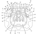
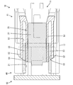
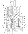
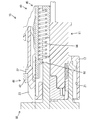
- FIG. 1 is a cross-sectional view taken along the line AA in FIG. 1 before the first housing and the second housing are fitted together.
- 1 is a cross-sectional view taken along the line AA in FIG. 1 in a state where the first housing and the second housing are properly fitted and the detection member is displaced to the detection position.
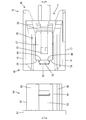
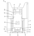
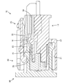
- FIG. 2 is a sectional side view taken along the line BB in FIG. 2 in the process of fitting the first housing and the second housing. 2 is a side cross-sectional view taken along the line BB of FIG. 2 in a state where the first housing and the second housing are further fitted from the state of FIG.
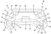
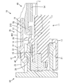
- FIG. 14 is a side cross-sectional view taken along the line BB of FIG. 2 in a state in which the first housing and the second housing are further fitted from the state of FIG. CC sectional view of FIG. DD sectional view of FIG. FIG.
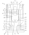
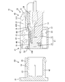
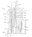
- FIG. 13 is a side sectional view taken along the line DD in FIG. 1 in the same state as FIG.
- FIG. 3 is a side sectional view taken along the line DD in FIG. 1 in the same state as FIG. 3
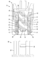
- FIG. 2 is a cross-sectional side view taken along the line BB in FIG. 2 in a state where both housings are properly fitted, the detection member is displaced to the initial position, and the lock arm is unlocked.
- the connector of the present invention Constituting the deformation regulating portion on the peripheral wall portion side, and a rib in a form protruding from the opening edge portion of the opening portion to the outer peripheral side;
- the deformation restricting portion on the detection member side may be configured to include a groove portion configured to sandwich the rib in a substantially circumferential direction and sandwich an opening edge portion of the opening portion and the rib in a substantially radial direction. . According to this configuration, in addition to restricting the opening from expanding or narrowing in the circumferential direction, it is also possible to regulate relative displacement of the detection member in the radial direction with respect to the circumferential wall.
- the connector of the present invention Between the terminal accommodating portion and the peripheral wall portion, a lock arm for locking the first housing and the second housing in a fitted state is disposed,
- the detection member and the lock arm may overlap at least partially with respect to the direction in which the terminal accommodating portion and the lock arm are arranged. According to this configuration, since the detection member and the lock arm overlap at least partially in the direction in which the terminal accommodating portion and the lock arm are arranged, the first housing can be downsized.
- the connector of the present embodiment includes a synthetic resin first housing 10, a synthetic resin detection member 40 attached to the first housing 10, a metal spring member 56 attached to the first housing 10, and a synthetic resin. And a second housing 60 made of metal.
- the first housing 10 includes a terminal housing portion 11 and a peripheral wall portion 17 that surrounds the terminal housing portion 11.
- the terminal accommodating portion 11 includes a housing body 12 and a front member 13 assembled to the front end portion of the housing body 12.
- the terminal accommodating portion 11 accommodates a pair of left and right female terminal fittings 14.
- a first stopper 16 is formed on the upper surface 15 of the terminal accommodating portion 11 (housing main body 12) so that the central portion in the width direction protrudes in a stepped shape.
- the first stopper 16 is a means for holding the detection member 40 at the initial position in a state where the detection member 40 described later is biased toward the detection position by the spring member 56.
- the peripheral wall portion 17 includes a lower wall portion 18 that faces the lower surface of the terminal housing portion 11, a pair of left and right side wall portions 19 that face the side surfaces of the terminal housing portion 11, and upper ends of both side wall portions 19. It comprises a pair of left and right projecting portions 20 that project in a cantilevered manner from the edge (the end edge opposite to the lower wall portion 18).
- a space between the outer peripheral surface of the terminal accommodating portion 11 and the inner peripheral surface of the peripheral wall portion 17 is a fitting space 21 for fitting the hood portion 62 of the second housing 60.
- the fitting space 21 is open to the front (front side) of the first housing 10.
- the peripheral wall portion 17 has a form in which a part (upper surface portion) in the circumferential direction is cut out, and the cut-out portion exposes the fitting space 21 and the detection member 40 to the outer peripheral side (upward) of the peripheral wall portion 17.
- An opening 22 is formed.
- the formation range of the opening 22 in the front-rear direction (the direction parallel to the fitting direction of both housings 10 and 60) is the entire region from the front end to the rear end of the peripheral wall portion 17. 22 is open to the front of the first housing 10.
- the front end of the peripheral wall portion 17 is at the same position as the front end of the terminal accommodating portion 11 in the front-rear direction.
- the rear end of the peripheral wall portion 17 continues to the outer periphery of the terminal accommodating portion 11 at a substantially central position in the front-rear direction of the terminal accommodating portion 11. That is, the peripheral wall portion 17 has a form that extends forward in a cantilevered manner.
- a pair of symmetrical ribs 23 are formed on the peripheral wall portion 17.
- the rib 23 has a form extending linearly in the front-rear direction along the extended end edge of the overhanging portion 20, that is, the left and right side edges in the opening region of the opening 22.
- the rib 23 has a shape protruding toward the outer peripheral side of the peripheral wall portion 17.
- the rib 23 functions to restrict the deformation of the peripheral wall portion 17 so as to change the opening width of the opening portion 22 and functions as a guide when the detection member 40 is moved between the initial position and the detection position. Have both.
- the peripheral wall portion 17 is integrally provided with a cover portion 24 that protrudes from the front end edge (front end edge) of the overhang portion 20 toward the inner peripheral side (fitting space 21 side). Is formed.
- a pair of cover portions 24 are provided symmetrically.
- the formation region of the cover portion 24 in the circumferential direction is a range extending from the upper end portion of the side wall portion 19 to the entire region of the overhang portion 20.
- a lock arm 25 is formed integrally with the housing main body 12 constituting the terminal accommodating portion 11.
- the lock arm 25 includes a pair of left and right leg portions 26 projecting from the upper surface 15 of the terminal accommodating portion 11, and a substantially flat plate extending in a cantilever manner from the leg portion 26 forward and rearward along the outer surface of the terminal accommodating portion 11.
- the arm portion 27 is integrally formed.
- the lock arm 25 is disposed in the fitting space 21 so as to face the upper surface 15 of the terminal accommodating portion 11 substantially in parallel.
- the lock arm 25 can be elastically deformed into a seesaw shape with the leg portion 26 as a fulcrum.
- a lock projection 28 that protrudes downward (the terminal accommodating portion 11).
- the formation range in the width direction of the lock protrusion 28 is only the central portion of the lock arm 25.
- a pair of left and right cutout portions 29 are formed at the front end portion of the lock arm 25 in a form in which both end portions in the width direction where the lock protrusions 28 are not formed are cut out.
- a portion of the front end portion of the lock arm 25 where the lock protrusions 28 are formed between the notches 29 is a narrow portion 30.
- a lock release operation portion 31 is formed so as to protrude in a direction away from the terminal accommodating portion 11 (on the side opposite to the lock protrusion 28). .
- the height of the outer surface 31S of the unlocking operation portion 31 with respect to the upper surface 15 of the terminal accommodating portion 11 in the direction in which the upper surface 15 of the terminal accommodating portion 11 and the lock arm 25 face each other (hereinafter referred to as “height direction”). Is higher than the outer surface of the arm portion 27. That is, the outer surface 31 ⁇ / b> S of the unlocking operation unit 31 is located at a position (the highest position) farthest from the upper surface 15 of the terminal accommodating unit 11 in the lock arm 25. Further, the outer surface 31 ⁇ / b> S of the unlocking operation portion 31 is located at a position higher than the upper end edge of the rib 23 of the peripheral wall portion 17.
- a second stopper 32 is formed on the upper surface of the arm portion 27 so as to project the detection member 40, which will be described later, from the initial position to the detection position side to restrict the movement of the detection member 40 that has reached the detection position. Yes.
- the position of the outer surface (upper surface) of the second stopper 32 with respect to the upper surface 15 of the terminal accommodating portion 11 is lower than the outer surface 31S of the unlocking operation portion 31 but higher than the upper end edge of the rib 23.
- the formation range of the second stopper 32 in the width direction is only the central portion of the lock arm 25, and the width dimension of the second stopper 32 is smaller than the width dimension of the narrow portion 30.
- the detection member 40 is configured by integrally forming a frame portion 41 constituting the outer surface 40S of the detection member 40 and a connecting portion 54.
- the frame portion 41 includes a front frame 42 whose length direction is directed in the width direction and a pair of left and right symmetrical side frames 43 extending rearward from both left and right ends of the front frame 42.
- the upper surfaces of the front frame 42 and the side frame 43 are outer surfaces 40 ⁇ / b> S arranged at the highest position among the detection members 40.
- the height of the outer surface 40S is substantially the same height as the outer surface 31S of the lock arm 25.
- the front frame 42 has a substantially flat plate shape that is substantially parallel to the upper surface 15 of the terminal accommodating portion 11.
- the front end edge of the front frame 42 is located at the foremost end of the detection member 40 and extends substantially straight in the left-right direction.
- the size of the front frame 42 in the front-rear direction is small at the center in the width direction and is large at both ends in the width direction.
- the part which protrudes back in the width direction both ends side part of the front frame 42 is a pair of reinforcement part 44.
- the reinforcing portion 44 is connected to the front end portion of the side frame 43 and functions as a means for increasing the strength of the front frame 42.
- the formation region in the width direction of the pair of reinforcing portions 44 is a region corresponding to the notch 29 of the lock arm 25, that is, a range not corresponding to the narrow portion 30.
- the center portion sandwiched between the pair of reinforcing portions 44 in the front frame 42 is moved. Furthermore, it functions as a means for holding the detection member 40 at the detection position by contacting the second stopper 32. As shown in FIG. 16, the full width region of the front frame 42 functions as a lock release restricting means for restricting the lock arm 25 at the lock position from being elastically displaced to the lock release position.
- the side frame 43 includes a pair of left and right spring accommodating portions 45.
- the spring accommodating portion 45 is composed of a cylindrical portion 46 whose rear end is partially blocked by the rear wall 47 with its axis line oriented in the front-rear direction, and an arc-shaped portion 48 that is connected to the front end of the cylindrical portion 46 in a flush manner. Is done.
- the arc-shaped portion 48 is formed on the outer side in the width direction of the upper quadrant arc region and the two side portions. This is a range corresponding to the quarter arc region of the side portion located at.
- a space elongated in the front-rear direction surrounded by the cylindrical portion 46 and the arc-shaped portion 48 is a spring accommodating space 49.
- a spring member 56 made of a compression coil spring is accommodated coaxially.
- a front wall 50 projecting inward is formed at the front edge of the arc-shaped portion 48.
- the front surface of the front wall 50 is located slightly behind the front edge of the front frame 42.
- the front wall 50 partially covers the opening area at the front end of the spring accommodating space 49.
- the spring member 56 is sandwiched between the rear wall 47 and the front wall 50, so that separation from the spring accommodating space 49 is restricted. Of the front end portion of the spring member 56, a region not corresponding to the front wall 50 is exposed to the front (front side).
- the side frame 43 has a standing wall portion 51 integrally formed with the spring accommodating portion 45.
- the standing wall portion 51 has a form that rises upward from the inner side edge portion on the upper surface of the spring accommodating portion 45, and extends linearly in the front-rear direction.
- the upper end edge of the upright wall portion 51 is connected substantially at right angles to the left and right ends of the front frame 42.
- the side frame 43 has a flange portion 52 that is integrally formed with the standing wall portion 51.
- the flange portion 52 has a shape that protrudes outward in the width direction from the upper end edge of the standing wall portion 51 and extends obliquely downward so as to approach the spring accommodating portion 45.
- the flange portion 52 extends in the front-rear direction.
- the upper end edge of the upright wall portion 51 and the upper end surface of the flange portion 52 constitute the outer surface 40S of the detection member 40, similarly to the upper surface of the front frame 42.
- the side frame 43 has a pair of left and right groove portions 53.
- the groove portion 53 is surrounded by the upper surface of the spring accommodating portion 45, the standing wall portion 51, and the flange portion 52, and the front end is open. Moreover, the groove part 53 is open
- the groove portion 53 cooperates with the rib 23 to restrict the deformation of the peripheral wall portion 17 so as to change the opening width of the opening portion 22, and the detection member 40 between the initial position and the detection position. It functions as a guide when moving.
- the connecting portion 54 connects the lower ends (cylindrical portions 46) at the rear end of the side frame 43.
- the detection member 40 is configured by the connecting portion 54 and the frame portion 41 to have a frame shape in which the planar shape is a substantially square shape.
- the connecting portion 54 is formed with a bending locking piece 55 in a form that cantilevered forward.
- the flexure locking piece 55 is positioned at the center in the width direction and can be elastically displaced in the vertical direction (direction approaching / separating from the upper surface 15 of the terminal accommodating portion 11).
- the detection member 40 having the above configuration is assembled to the first housing 10 so as to be movable between an initial position and a detection position.
- the initial position is set at the front end in the displacement range of the detection member 40
- the detection position is set at the rear end in the displacement range of the detection member 40.
- the detection member 40 is assembled from the rear of the first housing 10 so that the groove 53 is fitted to the rib 23. By the fitting of the rib 23 and the groove 53, the detection member 40 is guided so as to be able to move smoothly between the initial position and the detection position.
- the detection member 40 In a state where the detection member 40 is assembled to the first housing 10, at least the front end side region of the spring accommodating portion 45 is located in the fitting space 21, the standing wall portion 51 penetrates the opening portion 22, and the entire front frame 42. And the whole collar part 52 is located in the outer peripheral side (outside the fitting space 21) rather than the surrounding wall part 17.
- the inner edges of the left and right side frames 43 are positioned slightly outward in the width direction from the left and right outer edges of the lock arm 25 (arm part 27).
- the entire lock arm 25 is within the height range from the upper end to the lower end of the detection member 40 in the height direction.
- the front end portion of the connecting portion 54 and the entire bending locking piece 55 are located below the lock arm 25 (between the lock arm 25 and the terminal accommodating portion 11).
- the front frame 42 is positioned above the arm portion 27 of the lock arm 25.
- the front end surface 45F of the spring accommodating portion 45 of the side frame 43 abuts against the cover portion 24 of the peripheral wall portion 17 from the rear, and is bent and locked.
- the front end portion of the piece 55 is engaged with the first stopper 16 from the front.
- the detection member 40 is held at the initial position by the contact with the cover 24 and the locking with the first stopper 16.
- the front end face 45F of the spring accommodating part 45 is located behind the front end face of the standing wall part 51 and the front frame 42.
- the bending locking piece 55 comes off from the first stopper 16, and the front frame 42 contacts the second stopper 32 from the front (initial position side). Touch. By this abutting action, the detection member 40 is restricted from being displaced backward from the detection position.
- the front frame 42 When the detection member 40 is in the initial position, the front frame 42 is positioned in front of the front edge of the lock arm 25 as shown in FIGS. That is, the rear edge of the central portion where the reinforcing portion 44 is not formed among the rear edges of the front frame 42 is positioned slightly forward of the front edge of the narrow portion 30 of the lock arm 25. Accordingly, as shown in FIG. 13, the lock arm 25 is elastically displaced to a lock release position where the front end side region where the lock protrusion 28 is formed is displaced upward to advance into the space surrounded by the frame portion 41. be able to. In a state where the detection member 40 is in the detection position, the front frame 42 is positioned so as to overlap above the front end edge of the lock arm 25 as shown in FIGS. Therefore, even if the lock arm 25 attempts to elastically move to the unlocked position, the lock arm 25 abuts against the front frame 42, so that the elastic displacement to the unlocked position is restricted and the lock arm 25 is held at the locked position.
- the second housing 60 is configured by integrally forming a terminal holding portion 61 and a hood portion 62 extending in a rectangular tube shape from the terminal holding portion 61 toward the front side. ing.
- a lock receiving portion 64 protruding from the outer surface (upper surface) is formed on the upper surface wall 63 constituting the hood portion 62.
- a pair of pressing portions 65 arranged so as to sandwich the lock receiving portion 64 in the width direction are formed to protrude.
- the spring member 56 is pushed from the front by the pressing portion 65 of the hood portion 62 as shown in FIG. It is elastically deformed between the face wall 47. Due to the elastic deformation of the spring member 56, a biasing force in the direction from the initial position toward the detection position is applied to the detection member 40. However, as shown in FIG. 13, since the bending locking piece 55 is held in a state locked to the first stopper 16, the detection member 40 remains in the initial position while being urged toward the detection position. ing.
- both housings 10 and 60 come into contact with each other, and the fitting operation is stopped.
- the bending locking piece 55 is displaced further upward by the upper surface wall 63 of the hood portion 62, the bending locking piece 55 is completely detached from the first stopper 16.
- the detection member 40 is moved from the initial position to the detection position at a stroke by the urging of the spring member 56, and the front frame 42 comes into contact with the second stopper 32 as shown in FIGS. Stops at the detection position.
- the fact that the detection member 40 has been displaced to the detection position can be recognized by visual observation and the collision sound between the front frame 42 and the second stopper 32.
- the detection member 40 When the detection member 40 is displaced to the detection position, the fitting of the two housings 10 and 60 is completed. If the fitting operation is interrupted in a state in which the housings 10 and 60 are not completely fitted, the detection member 40 does not move to the detection position and remains at the initial position. Therefore, based on whether or not the detection member 40 has moved from the initial position to the detection position, the operator can detect whether or not the two housings 10 and 60 are properly fitted.
- the two housings 10 and 60 are first locked in the normal fitting state by the lock arm 25, and thereafter the detection is performed.
- the movement of the member 40 to the detection position is allowed. Therefore, when the fitting operation is interrupted in the half-fitted state, the detection member 40 is held at the initial position, so that the fitting operation can be performed without performing the operation of returning the detection member 40 from the detection position to the initial position. Can be resumed.
- the detection member 40 at the detection position is first resisted against the bias of the spring member 56. Move to the initial position. Then, since the front end portion of the lock arm 25 is released from the displacement restriction by the front frame 42, the lock arm 25 can be elastically displaced in the unlocking direction. Therefore, if the unlocking operation portion 31 is pushed downward while the detection member 40 is pushed and held at the initial position, the lock arm 25 is elastically displaced in a seesaw shape as shown in FIG. The protrusion 28 is disengaged from the lock receiving portion 64, and the lock by the lock arm 25 is released. Thereafter, both the housings 10 and 60 may be pulled apart while the lock arm 25 is displaced to the unlocking position.
- the connector of the present embodiment includes a first housing 10 having a shape in which the terminal housing portion 11 is surrounded by the peripheral wall portion 17, a second housing 60 that can be fitted to the first housing 10, the terminal housing portion 11, and the peripheral wall portion 17.
- a detecting member 40 is provided for detecting the fitting state of both housings 10 and 60 based on whether or not it moves from the initial position to the detecting position in the fitting space 21 between them. Furthermore, it is the form which notched the part in the circumferential direction of the surrounding wall part 17, Comprising: It forms in the opening part 22 which exposes the detection member 40 to an outer peripheral side, the surrounding wall part 17, and the detection member 40, and it mutually fits. Deformation restricting portions (ribs 23 and groove portions) that allow the detecting member 40 to move between the initial position and the detecting position and restrict the deformation of the peripheral wall portion 17 so as to change the opening width of the opening portion 22. 53).
- the connector of the present embodiment can reduce the size of the first housing 10 as compared with the case where the peripheral wall portion exists on the outer peripheral side of the detection member. Further, if the opening 22 is formed in the peripheral wall portion 17, there is a concern that the peripheral wall portion 17 is deformed so as to change the opening width of the opening portion 22, but in this embodiment, the opening in the peripheral wall portion 17 is concerned. The peripheral wall portion 17 is prevented from being deformed by fitting the rib 23 at the opening edge of the portion 22 and the groove portion 53 formed in the detection member 40.
- the rib 23 that is a deformation restricting portion of the peripheral wall portion 17 has a form protruding from the opening edge portion of the opening portion 22 to the outer peripheral side, and the groove portion 53 that is a deformation restricting portion on the detection member 40 side is substantially the rib 23. While sandwiching in the circumferential direction, the opening edge portion of the opening 22 and the rib 23 are sandwiched in the substantially radial direction. According to this configuration, in addition to restricting the opening 22 from expanding or narrowing in the circumferential direction, the relative displacement of the detection member 40 relative to the peripheral wall 17 in the radial direction can also be restricted.
- a lock arm 25 for locking both housings 10 and 60 in a fitted state is disposed in the fitting space 21 between the terminal containing portion 11 and the peripheral wall portion 17.
- the detection member 40 and the lock arm 25 overlap at least partially with respect to the vertical direction (height direction) in which 25 is arranged.
- the first housing 10 can be reduced in size by at least partially overlapping the detection member 40 and the lock arm 25 in the direction in which the terminal accommodating portion 11 and the lock arm 25 are arranged.
- the lock arm 25 and the detection member 40 are arranged along the upper surface 15 of the first housing 10, and the detection member 40 constitutes an outer surface 40S of the detection member 40 to surround and lock the lock arm 25.
- the frame part 41 of the form which exposes the outer surface 31S of the arm 25 is provided.
- the frame portion 41 is disposed on the inner side of the outer surface 31S of the lock arm 25 in the vertical direction (height direction) in which the upper surface 15 of the first housing 10 and the lock arm 25 face each other. According to this configuration, the size can be reduced in the direction in which the upper surface 15 of the first housing 10 and the lock arm 25 face each other.
- the connector of this embodiment includes a spring member 56 that urges the detection member 40 toward the detection position by being pressed by the pressing portion 65 of the second housing 60 in the process of fitting both the housings 10, 60, and both In the process of fitting the housings 10 and 60, the first stopper 16 that holds the detection member 40 in the initial position against the bias of the spring member 56 and releases the holding of the detection member 40 when both the housings 10 and 60 are fitted. And the front frame 42 that forms the frame portion 41 and extends in the width direction intersecting the moving direction of the detection member 40, and the detection member 40 released from the holding of the first stopper 16 urges the spring member 56.
- the second stopper 32 stops the detection member 40 at the detection position by bringing the front frame 42 into contact when the detection position is reached.
- the front frame 42 is formed with a reinforcing portion 44 that is built up in the front-rear direction intersecting the vertical direction in which the upper surface 15 of the first housing 10 and the lock arm 25 face each other. As strength increases. Therefore, in the direction in which the upper surface 15 of the first housing 10 and the lock arm 25 face each other, it is possible to reduce the thickness of the front frame 42 and further reduce the size.
- the detection member 40 restricts the elastic displacement of the lock arm 25 in the unlocking direction when the detection member 40 is in the detection position, and unlocks the lock arm 25 when the detection member 40 is in the initial position.
- a front frame 42 is formed as an unlocking restricting portion that allows elastic displacement in the direction.
- the lock arm 25 is formed with an unlock operation portion 31 that is exposed when the detection member 40 is in the initial position and that can be directly unlocked manually.
- the detection member 40 at the detection position is moved to the initial position against the bias of the spring member 56, and thereafter Then, the unlocking operation part 31 is unlocked by direct manual operation to elastically displace the lock arm 25 in the unlocking direction, and in this state, both the housings 10 and 60 are pulled apart. That is, in this embodiment, when releasing the lock by the lock arm 25, the operation of moving the detection member 40 from the detection position to the initial position, and the operation of releasing the hand from the detection member 40 and operating the unlock operation unit 31. Need to be performed separately, that is, a two-action operation. Therefore, the lock is not released only by pressing the detection member 40 or the unlocking operation unit 31 in one direction, and both the housings 10 and 60 can be reliably held in the locked state.
- the detection member 40 is arranged at an initial position near the front opening region in the fitting space 21, and when both the housings 10 and 60 are properly fitted, the detection member 40 is It is displaced to the detection position at the back in the fitting space 21. And the cover part 24 extended from the opening edge of the front side of the fitting space 21 is distribute
- the detection member 40 Since it contacts the portion 24, the detection member 40 is not pushed into the detection position by the hood portion 62 while both the housings 10, 60 are unfitted or half-fitted. Therefore, it is possible to prevent the detection operation failure from occurring due to the detection member 40 being pushed by the hood portion 62.
- the cover part 24 is formed integrally with the peripheral wall part 17, the number of parts can be reduced as compared with the case where the cover part is a separate part from the peripheral wall part. Further, the cover 24 is configured to stop the detection member 40 at the initial position when the detection member 40 is displaced from the detection position to the initial position. That is, the cover 24 has both a function of preventing the hood 62 from coming into contact with the detection member 40 and a function of stopping the detection member 40 at the initial position. Therefore, the shapes of the first housing 10 and the detection member 40 can be simplified as compared with the case where the means for stopping the detection member 40 is formed separately from the cover 24.
- the deformation restricting portion on the peripheral wall portion side is a protruding rib
- the deformation restricting portion on the detection member side is a recessed groove portion, but conversely, on the peripheral wall portion side
- the deformation restricting portion may be a groove
- the deformation restricting portion on the detection member side may be a rib
- the rib on the peripheral wall portion side and the rib on the detecting member side may be opposed to each other in the circumferential direction.
- the opening portion opens over the entire region from the front end to the rear end of the peripheral wall portion, but the opening forming region in the front-rear direction extends from the front end to the rear end of the peripheral wall portion. It may be only a part of the area.
- the detection member and the lock arm are at least partially overlapped in the direction in which the terminal accommodating portion and the lock arm are arranged in the above embodiment, the detection member and the lock are in the direction in which the terminal accommodating portion and the lock arm are arranged. It is good also as a form where an arm does not overlap.
Landscapes
- Details Of Connecting Devices For Male And Female Coupling (AREA)
Abstract
Priority Applications (6)
| Application Number | Priority Date | Filing Date | Title |
|---|---|---|---|
| JP2015515680A JP5885096B2 (ja) | 2013-05-08 | 2013-05-08 | コネクタ |
| CN201380076438.1A CN105191012A (zh) | 2013-05-08 | 2013-05-08 | 连接器 |
| KR1020157031921A KR101661873B1 (ko) | 2013-05-08 | 2013-05-08 | 커넥터 |
| PCT/JP2013/062971 WO2014181410A1 (fr) | 2013-05-08 | 2013-05-08 | Connecteur |
| US14/787,344 US9484684B2 (en) | 2013-05-08 | 2013-05-08 | Connector with peripheral wall having an opening and a detector slidably engaging the peripheral wall adjacent the opening for preventing widening of the opening |
| EP13883938.6A EP2996208A4 (fr) | 2013-05-08 | 2013-05-08 | Connecteur |
Applications Claiming Priority (1)
| Application Number | Priority Date | Filing Date | Title |
|---|---|---|---|
| PCT/JP2013/062971 WO2014181410A1 (fr) | 2013-05-08 | 2013-05-08 | Connecteur |
Publications (1)
| Publication Number | Publication Date |
|---|---|
| WO2014181410A1 true WO2014181410A1 (fr) | 2014-11-13 |
Family
ID=51866914
Family Applications (1)
| Application Number | Title | Priority Date | Filing Date |
|---|---|---|---|
| PCT/JP2013/062971 WO2014181410A1 (fr) | 2013-05-08 | 2013-05-08 | Connecteur |
Country Status (6)
| Country | Link |
|---|---|
| US (1) | US9484684B2 (fr) |
| EP (1) | EP2996208A4 (fr) |
| JP (1) | JP5885096B2 (fr) |
| KR (1) | KR101661873B1 (fr) |
| CN (1) | CN105191012A (fr) |
| WO (1) | WO2014181410A1 (fr) |
Cited By (2)
| Publication number | Priority date | Publication date | Assignee | Title |
|---|---|---|---|---|
| FR3035745A1 (fr) * | 2015-04-29 | 2016-11-04 | Sumitomo Wiring Systems | Connecteur |
| JP7393296B2 (ja) | 2020-05-15 | 2023-12-06 | 矢崎総業株式会社 | 防水コネクタ |
Families Citing this family (12)
| Publication number | Priority date | Publication date | Assignee | Title |
|---|---|---|---|---|
| JP6515825B2 (ja) * | 2016-01-21 | 2019-05-22 | 住友電装株式会社 | コネクタ |
| JP6213583B2 (ja) * | 2016-01-27 | 2017-10-18 | 住友電装株式会社 | コネクタ |
| JP6569131B2 (ja) * | 2016-04-26 | 2019-09-04 | 株式会社オートネットワーク技術研究所 | 嵌合検知機能を有する電気接続装置 |
| JP6445495B2 (ja) * | 2016-07-29 | 2018-12-26 | 矢崎総業株式会社 | コネクタ |
| JP6417369B2 (ja) * | 2016-07-29 | 2018-11-07 | 矢崎総業株式会社 | コネクタ |
| JP6417370B2 (ja) * | 2016-07-29 | 2018-11-07 | 矢崎総業株式会社 | コネクタ |
| JP6135834B1 (ja) * | 2017-01-20 | 2017-05-31 | 第一精工株式会社 | 電気コネクタ、及び電気コネクタのロック部材 |
| JP2018181787A (ja) * | 2017-04-21 | 2018-11-15 | 住友電装株式会社 | コネクタ |
| US10283904B2 (en) * | 2017-08-04 | 2019-05-07 | Yazaki Corporation | Connector |
| JP2019050169A (ja) * | 2017-09-12 | 2019-03-28 | 住友電装株式会社 | コネクタ |
| JP2020080270A (ja) * | 2018-11-14 | 2020-05-28 | 住友電装株式会社 | コネクタ |
| JP7230739B2 (ja) * | 2019-08-09 | 2023-03-01 | 住友電装株式会社 | コネクタ |
Citations (5)
| Publication number | Priority date | Publication date | Assignee | Title |
|---|---|---|---|---|
| JPH11111390A (ja) * | 1997-08-05 | 1999-04-23 | Sumitomo Wiring Syst Ltd | 嵌合検知コネクタ |
| JP2001085111A (ja) * | 1999-09-10 | 2001-03-30 | Sumitomo Wiring Syst Ltd | コネクタ |
| JP2002056933A (ja) * | 2000-08-10 | 2002-02-22 | Sumitomo Wiring Syst Ltd | コネクタ |
| JP2003077590A (ja) * | 2001-09-06 | 2003-03-14 | Sumitomo Wiring Syst Ltd | コネクタ |
| JP2008159504A (ja) * | 2006-12-26 | 2008-07-10 | Sumitomo Wiring Syst Ltd | コネクタ |
Family Cites Families (18)
| Publication number | Priority date | Publication date | Assignee | Title |
|---|---|---|---|---|
| TW353849B (en) | 1996-11-29 | 1999-03-01 | Matsushita Electric Ind Co Ltd | Electric-to-mechanical-to-acoustic converter and portable terminal unit |
| DE69838570T2 (de) | 1997-08-05 | 2008-07-24 | Sumitomo Wiring Systems, Ltd., Yokkaichi | Verbinder mit Kupplungserkennungsmitteln |
| US5910027A (en) * | 1997-10-08 | 1999-06-08 | Ut Automotive Dearborn, Inc. | Connector position assurance |
| EP0975066B1 (fr) | 1998-07-22 | 2011-08-24 | Sumitomo Wiring Systems, Ltd. | Connecteur ayant des moyens de détection d' engagement |
| JP3506215B2 (ja) * | 1998-09-07 | 2004-03-15 | 住友電装株式会社 | 嵌合検知コネクタ |
| US6261116B1 (en) * | 1999-11-22 | 2001-07-17 | Yazaki North America, Inc. | Connector position assurance element with lock protection feature |
| US6435895B1 (en) * | 2001-04-27 | 2002-08-20 | Delphi Technologies, Inc. | Connector position assurance device |
| JP3609379B2 (ja) * | 2002-01-31 | 2005-01-12 | 日本圧着端子製造株式会社 | ロック機構付き電気コネクタ |
| US6780045B2 (en) * | 2002-03-06 | 2004-08-24 | Tyco Electronics Corporation | Connector position assurance device |
| JP4039199B2 (ja) | 2002-10-10 | 2008-01-30 | 住友電装株式会社 | コネクタ |
| JP2004241275A (ja) * | 2003-02-06 | 2004-08-26 | Yazaki Corp | 半嵌合防止コネクタ |
| JP4179129B2 (ja) * | 2003-10-09 | 2008-11-12 | 住友電装株式会社 | コネクタ |
| DE102005008585B4 (de) * | 2004-02-25 | 2013-05-16 | Sumitomo Wiring Systems, Ltd. | Verbinderanordnung |
| JP4544065B2 (ja) * | 2005-07-13 | 2010-09-15 | 住友電装株式会社 | コネクタ |
| KR20080044510A (ko) * | 2006-11-16 | 2008-05-21 | 엘에스전선 주식회사 | 커넥터의 결합상태를 고정하는 장치 및 이를 구비한 커넥터세트 |
| US7326074B1 (en) * | 2006-12-06 | 2008-02-05 | J.S.T. Corporation | Connector position assurance device and a connector assembly incorporating the connector position assurance device |
| US8882528B2 (en) * | 2010-12-15 | 2014-11-11 | Sumitomo Wiring Systems, Ltd. | Connector |
| US8628344B2 (en) * | 2011-10-12 | 2014-01-14 | Yazaki North America, Inc. | Connector and terminal positioning mechanism |
-
2013
- 2013-05-08 WO PCT/JP2013/062971 patent/WO2014181410A1/fr active Application Filing
- 2013-05-08 KR KR1020157031921A patent/KR101661873B1/ko active IP Right Grant
- 2013-05-08 JP JP2015515680A patent/JP5885096B2/ja not_active Expired - Fee Related
- 2013-05-08 US US14/787,344 patent/US9484684B2/en active Active
- 2013-05-08 CN CN201380076438.1A patent/CN105191012A/zh active Pending
- 2013-05-08 EP EP13883938.6A patent/EP2996208A4/fr not_active Withdrawn
Patent Citations (6)
| Publication number | Priority date | Publication date | Assignee | Title |
|---|---|---|---|---|
| JPH11111390A (ja) * | 1997-08-05 | 1999-04-23 | Sumitomo Wiring Syst Ltd | 嵌合検知コネクタ |
| JP3303782B2 (ja) | 1997-08-05 | 2002-07-22 | 住友電装株式会社 | 嵌合検知コネクタ |
| JP2001085111A (ja) * | 1999-09-10 | 2001-03-30 | Sumitomo Wiring Syst Ltd | コネクタ |
| JP2002056933A (ja) * | 2000-08-10 | 2002-02-22 | Sumitomo Wiring Syst Ltd | コネクタ |
| JP2003077590A (ja) * | 2001-09-06 | 2003-03-14 | Sumitomo Wiring Syst Ltd | コネクタ |
| JP2008159504A (ja) * | 2006-12-26 | 2008-07-10 | Sumitomo Wiring Syst Ltd | コネクタ |
Non-Patent Citations (1)
| Title |
|---|
| See also references of EP2996208A4 |
Cited By (2)
| Publication number | Priority date | Publication date | Assignee | Title |
|---|---|---|---|---|
| FR3035745A1 (fr) * | 2015-04-29 | 2016-11-04 | Sumitomo Wiring Systems | Connecteur |
| JP7393296B2 (ja) | 2020-05-15 | 2023-12-06 | 矢崎総業株式会社 | 防水コネクタ |
Also Published As
| Publication number | Publication date |
|---|---|
| US9484684B2 (en) | 2016-11-01 |
| EP2996208A1 (fr) | 2016-03-16 |
| JP5885096B2 (ja) | 2016-03-15 |
| JPWO2014181410A1 (ja) | 2017-02-23 |
| EP2996208A4 (fr) | 2016-04-20 |
| KR101661873B1 (ko) | 2016-09-30 |
| KR20150140353A (ko) | 2015-12-15 |
| US20160064875A1 (en) | 2016-03-03 |
| CN105191012A (zh) | 2015-12-23 |
Similar Documents
| Publication | Publication Date | Title |
|---|---|---|
| JP5885096B2 (ja) | コネクタ | |
| JP5029872B2 (ja) | レバー式コネクタ | |
| JP4492493B2 (ja) | レバー式コネクタ | |
| JP6607088B2 (ja) | コネクタ | |
| JP2015079710A (ja) | コネクタ | |
| CN110098527B (zh) | 电线盖及连接器 | |
| JP2013149384A (ja) | 電気コネクタ | |
| JP4760156B2 (ja) | レバー式コネクタ | |
| JP4385984B2 (ja) | コネクタ | |
| WO2018211560A1 (fr) | Connecteur | |
| JP2006086090A (ja) | コネクタ | |
| JP4049144B2 (ja) | レバー式コネクタ | |
| WO2014181413A1 (fr) | Connecteur | |
| JP6540553B2 (ja) | コネクタ | |
| JP2009037835A (ja) | コネクタ | |
| JP6571910B2 (ja) | レバー式コネクタ | |
| JP4375244B2 (ja) | コネクタ | |
| JP5999535B2 (ja) | コネクタ | |
| JP2009026590A (ja) | コネクタ | |
| WO2014181411A1 (fr) | Connecteur | |
| JP2015005490A (ja) | コネクタ | |
| JP5971203B2 (ja) | コネクタ | |
| JP5516353B2 (ja) | コネクタ | |
| JP2006120535A (ja) | レバー式コネクタ | |
| JP2012129076A (ja) | コネクタ |
Legal Events
| Date | Code | Title | Description |
|---|---|---|---|
| WWE | Wipo information: entry into national phase |
Ref document number: 201380076438.1 Country of ref document: CN |
|
| 121 | Ep: the epo has been informed by wipo that ep was designated in this application |
Ref document number: 13883938 Country of ref document: EP Kind code of ref document: A1 |
|
| ENP | Entry into the national phase |
Ref document number: 2015515680 Country of ref document: JP Kind code of ref document: A |
|
| WWE | Wipo information: entry into national phase |
Ref document number: 2013883938 Country of ref document: EP |
|
| WWE | Wipo information: entry into national phase |
Ref document number: 14787344 Country of ref document: US |
|
| ENP | Entry into the national phase |
Ref document number: 20157031921 Country of ref document: KR Kind code of ref document: A |
|
| NENP | Non-entry into the national phase |
Ref country code: DE |