WO2014175347A1 - 空気入りラジアルタイヤ - Google Patents
空気入りラジアルタイヤ Download PDFInfo
- Publication number
- WO2014175347A1 WO2014175347A1 PCT/JP2014/061465 JP2014061465W WO2014175347A1 WO 2014175347 A1 WO2014175347 A1 WO 2014175347A1 JP 2014061465 W JP2014061465 W JP 2014061465W WO 2014175347 A1 WO2014175347 A1 WO 2014175347A1
- Authority
- WO
- WIPO (PCT)
- Prior art keywords
- tire
- rim
- folded
- pneumatic radial
- carcass ply
- Prior art date
- Legal status (The legal status is an assumption and is not a legal conclusion. Google has not performed a legal analysis and makes no representation as to the accuracy of the status listed.)
- Ceased
Links
Images


Classifications
-
- B—PERFORMING OPERATIONS; TRANSPORTING
- B60—VEHICLES IN GENERAL
- B60C—VEHICLE TYRES; TYRE INFLATION; TYRE CHANGING; CONNECTING VALVES TO INFLATABLE ELASTIC BODIES IN GENERAL; DEVICES OR ARRANGEMENTS RELATED TO TYRES
- B60C15/00—Tyre beads, e.g. ply turn-up or overlap
- B60C15/0009—Tyre beads, e.g. ply turn-up or overlap features of the carcass terminal portion
- B60C15/0027—Tyre beads, e.g. ply turn-up or overlap features of the carcass terminal portion with low ply turn-up, i.e. folded around the bead core and terminating at the bead core
-
- B—PERFORMING OPERATIONS; TRANSPORTING
- B60—VEHICLES IN GENERAL
- B60C—VEHICLE TYRES; TYRE INFLATION; TYRE CHANGING; CONNECTING VALVES TO INFLATABLE ELASTIC BODIES IN GENERAL; DEVICES OR ARRANGEMENTS RELATED TO TYRES
- B60C15/00—Tyre beads, e.g. ply turn-up or overlap
- B60C15/0009—Tyre beads, e.g. ply turn-up or overlap features of the carcass terminal portion
- B60C15/0063—Tyre beads, e.g. ply turn-up or overlap features of the carcass terminal portion with ply turn-up portion diverging from carcass main portion
-
- B—PERFORMING OPERATIONS; TRANSPORTING
- B60—VEHICLES IN GENERAL
- B60C—VEHICLE TYRES; TYRE INFLATION; TYRE CHANGING; CONNECTING VALVES TO INFLATABLE ELASTIC BODIES IN GENERAL; DEVICES OR ARRANGEMENTS RELATED TO TYRES
- B60C15/00—Tyre beads, e.g. ply turn-up or overlap
- B60C15/0009—Tyre beads, e.g. ply turn-up or overlap features of the carcass terminal portion
- B60C2015/009—Height of the carcass terminal portion defined in terms of a numerical value or ratio in proportion to section height
Definitions
- the present invention relates to a pneumatic radial tire, and more particularly to a heavy duty pneumatic radial tire suitable for a construction vehicle.
- Japanese Unexamined Patent Application Publication Nos. 2007-196781 and 2009-1113715 disclose a structure in which the folded end of the carcass ply is positioned at the sidewall portion (near the center of the cross-sectional height) of the tire.
- the distortion generated near the folded end of the carcass ply is, firstly, the folded end is pulled out by internal pressure growth, secondly, the carcass ply is collapsed by filling the internal pressure, and thirdly, the carcass ply is collapsed and the rim flange This is caused by the three actions of the rubber being pushed out by the reaction force.
- an object of the present invention is to be able to suppress the distortion that occurs near the folded end of the carcass ply.
- a pneumatic radial tire includes a pair of bead portions in which bead cores are embedded, a main body portion that spans between the bead portions and is positioned between the bead cores, and a tire core in the tire width direction of the bead cores.
- the folded portion of the carcass ply has a position where the distance between the folded portion and the main body in the tire axial direction is minimized, so that the folded end of the carcass ply due to internal pressure growth Pulling is difficult to occur.
- the distance between the carcass ply body and the folded part is narrowed at the position where the distance is minimum, the rubber from the body part and the folded part due to the fall of the carcass ply or the reaction force from the rim flange. Extrusion is suppressed.
- the width in the tire axial direction from the tire outer surface to the turned-up portion is wider on the outer side in the tire width direction than the position where the distance is the smallest among the turned-up portions, so that the amount of rubber extruded per unit area is small.
- the position where the distance is minimum is set on the inner side in the tire radial direction from the height of the flange of the regular rim, the folded portion is easily pressed down by the rim reaction force. For this reason, the distortion which arises near the folding
- the position at which the distance is minimum passes through the center of curvature of the rim flange of the regular rim in the tire axial cross section and extends in the tire axial direction.
- the center of the center of curvature is on the outer side in the tire radial direction, above the direction extending 30 °, and below the direction extending 45 °.
- the curved portion of the sidewall portion is too far away from the ply end (the folded end of the carcass ply), and thus the above effect cannot be obtained effectively. This is because the end strain is not reduced and the function of the carcass ply as a tire skeleton is reduced. Further, if it is above the direction extending at 45 °, the folded end reaches the sidewall portion, and the thickness of the sidewall portion increases.
- the rim radius is a reference in a state where the pneumatic rim is assembled to the regular rim, a regular internal pressure is applied, and no load is applied.
- the height in the tire radial direction to the folded end of the folded portion is 15 to 20% of the tire cross-sectional height.
- the reason why the lower limit of the numerical range is set to 15% is that if the value is below this value, the height of the folded portion becomes too low and the function of the carcass ply as a tire skeleton is deteriorated. Also, the upper limit of the numerical range is set to 20% because if it exceeds this, the ply end (carcass ply folded end) is located in a range where the deformation is large at the time of load, and the distortion of the ply end increases.
- the pneumatic radial tire of the present invention it is possible to obtain an excellent effect that the length of the folded portion of the carcass ply can be suppressed and the distortion generated in the vicinity of the folded end can be suppressed.
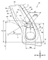
- FIG. 1 is a cross-sectional view showing one side of a tire equator in a pneumatic radial tire according to an embodiment. It is an expanded sectional view showing a bead part of a pneumatic radial tire concerning a conventional example.
- a pneumatic radial tire 10 relates to a heavy-duty pneumatic radial tire used for a construction vehicle or the like, and includes a pair of bead portions 12 and a carcass ply 14. As shown in FIG. 2, the pneumatic radial tire 10 further includes a tread portion 5 and a buttress portion 9. In FIG. 1, only one bead portion 12 is shown. In FIG. 2, one side of the tire equator CL is shown in the pneumatic radial tire 10.
- This pneumatic radial tire 10 has a thicker rubber gauge (rubber thickness) in the tread portion 5 than a pneumatic radial tire mounted on a passenger car or the like.
- the tire 1 satisfies DC / OD ⁇ 0.015 when the tire outer diameter is OD and the rubber gauge of the tread portion 5 at the position of the tire equator CL is DC.
- OD tire cross section height ⁇ 2 + rim diameter.
- the rim diameter corresponds to a rim radius R ⁇ 2.
- the tire cross-section height is a height from a point located on the innermost side in the radial direction to the outer surface of the tread portion 5 in a contact portion between the bead portion 12 and the rim 18.
- a plurality (for example, six layers) of belt layers 11 are provided between the tread portion 5 and the carcass ply 14 in the tire radial direction.
- the pair of bead portions 12 are portions where the bead cores 16 are respectively embedded, and are portions that are fitted to the rim 18 when the pneumatic radial tire 10 is assembled to the rim 18.
- the carcass ply 14 has, for example, a toroidal shape between the pair of bead portions 12, and a main body portion 14 ⁇ / b> A located between the bead cores 16, and a folded portion 14 ⁇ / b> B folded back from the inside in the tire width direction of the bead core 16. is doing.
- the carcass ply 14 has a position P at which the distance W between the main body portion 14A and the folded portion 14B in the tire axial direction is minimized.
- the tire axial direction is a direction parallel to the rotational axis of the pneumatic radial tire 10, and is the left-right direction (arrow XO-XI direction) in FIG.
- the tire radial direction is a radial direction of the pneumatic radial tire 10 and is a direction from the bottom to the top of FIG. 1 (arrow Y direction).
- the folded portion 14B has a curved portion 14D having the position P as the apex.
- the curved portion 14D is convexly curved inward in the tire axial direction (in the direction of the arrow XI in FIG. 1).
- the curvature radius r of the curved portion 14D varies depending on the tire size, but is, for example, 8 to 10 mm.
- the center of the curvature radius r is located on or near the line connecting the curvature center O of the rim flange 18F and the position P.
- the curved portion of the sidewall portion 20 is too far away from the ply end (the folded end 14C of the carcass ply 14), so that the above effect can be obtained effectively. This is because the ply end strain is not reduced and the function of the carcass ply 14 as a tire skeleton is reduced. Further, if it is above the direction extending at 45 °, the folded end 14C reaches the sidewall portion 20, and the thickness of the sidewall portion 20 increases.
- the sidewall portion 20 is a portion that connects the bead portion 12 and the tread portion 5 via the buttress portion 9 in the pneumatic radial tire 10.
- the distance W between the main body portion 14A and the turn-up portion 14B in the tire axial direction is the minimum (Wmin) at the position P.
- This distance Wmin is a distance from the outer surface in the tire radial direction of the coating rubber of the main body portion 14A to the inner surface in the radial direction of the coating rubber of the folded portion 14B.
- the distance Wmin is set to 25 to 45% with respect to the maximum width Wb of the bead core 16, for example.
- a distance W ′ from the turn-back end 14C to the main body 14A in the tire axial direction is 150 to 200% of the distance Wmin.
- the height Hc in the tire radial direction to the turn-up end 14C of the turn-up portion 14B with respect to the rim radius R is 15 to 15% of the tire cross-section height in a state where the load is attached to a normal rim, normal internal pressure is applied, and no load is applied. 20%.
- the folded portion 14 ⁇ / b> B is not extended to the sidewall portion 20 and is located in the region of the bead portion 12.
- the height Hp is 60 to 80% of the height Hc.
- the reason why the lower limit of the numerical range is set to 15% is that if the lower limit is reached, the height of the turn-up portion 14B becomes too low, and the function of the carcass ply 14 as a tire skeleton is deteriorated.
- the upper limit of the numerical range is set to 20% because if it exceeds this, the ply end (the folded end 14C of the carcass ply 14) is located in a range where deformation is large at the time of load, and the distortion of the ply end increases. is there.
- the distance in the tire width direction from the rim flange 18F at the position of the rim radius R to the turn-back end 14C is 16 mm. Further, the distance from the turn-back end 14C to the inner end in the tire width direction of the bead portion 12 is 43 mm.
- the height Hc may be set to 90 to 120% of the rim flange height Hf.
- the region surrounded by the bead core 16, the main body portion 14 ⁇ / b> A and the folded portion 14 ⁇ / b> B of the carcass ply 14, and the region further outside in the tire radial direction than the folded portion 14 ⁇ / b> B is made of hard rubber.
- a hard stiffener 22 is arranged. The width of the hard stiffener 22 is gradually reduced toward the outer side in the tire radial direction.
- the bead portion 12 is provided with a rubber chafer 28.
- a soft stiffener 23 having a hardness smaller than that of the hard stiffener 22 is disposed on the outer side in the tire axial direction of the hard stiffener 22 (arrow XO direction side).
- An alternate long and short dash line 30 in FIG. 1 indicates a boundary between the soft stiffener 23 and the hard stiffener 22.
- An alternate long and short dash line 32 indicates a boundary between the soft stiffener 23 and the rubber chafer 28 on the tire outer surface side, and indicates a boundary between the rubber chafer 28 and the inner rubber 38 on the tire inner surface side.
- An alternate long and short dash line 34 indicates a boundary between the rubber chafer 28 and the side rubber 36.
- An alternate long and short dash line 40 indicates a boundary between the side rubber 36 and the soft stiffener 23.
- the hard stiffener 22 is in contact with the folded portion 14B in the region radially inward of the tire from the position point P where the distance W is minimum, but is separated from the folded portion 14B in the region radially outward of the position P. Accordingly, the region from the position P to the turn-back end 14C in the turn-back portion 14B is located in the soft stiffener 23.
- the “regular rim” refers to a standard rim in the applicable size specified in the 2011 YEAR BOOK issued by JATMA, for example, and the “regular internal pressure” similarly represents the 2011 YEAR BOOK issued by JATMA. Refers to the air pressure with respect to the maximum load at the applicable size and ply rating specified in.
- the main body portion of the carcass ply 14 and the folded portion 14B is narrowed at the position P where the distance W is the minimum, the main body portion and the folded portion 14B due to the fall of the carcass ply 14 or the reaction force from the rim flange 18F. Extrusion of rubber from between is suppressed.
- the width in the tire axial direction from the tire outer surface to the turned-up portion 14B is wider on the outer side in the tire width direction at the position P in the turned-up portion 14B, the amount of rubber extruded per unit area is reduced. Since the position P at which the distance W is minimized is set on the inner side in the tire radial direction with respect to the flange height Hf of the regular rim (rim 18), the folded portion 14B can be easily pressed by the rim reaction force. For this reason, it is possible to suppress the distortion that occurs in the vicinity of the folded end 14C of the carcass ply 14.
- the length of the turn-up portion 14B can be suppressed and the increase in the thickness of the sidewall portion of the tire can be suppressed.
- the configuration of the bead portion 12 other than the carcass ply 14, that is, the configuration of each reinforcing layer and rubber layer, can be changed as appropriate without departing from the gist of the present invention.
- the analysis results are as shown in Table 1.
- the numerical value of the shear strain is indicated by an index with the conventional example being 100, and the smaller the numerical value, the smaller the shear strain and the better the result.
Landscapes
- Engineering & Computer Science (AREA)
- Mechanical Engineering (AREA)
- Tires In General (AREA)
Abstract
カーカスプライの折返し部の長さを抑制しつつ、折返し端付近に生ずる歪を抑制できるようにすることを目的とする。 空気入りラジアルタイヤ(10)は、ビードコア(16)が設けられた一対のビード部(12)と、該ビード部(12)間を跨り、ビードコア(16)間に位置する本体部(14A)と、該ビードコア(16)のタイヤ幅方向の内側から外側へ折り返された折返し部(14B)とを有し、タイヤ軸方向における本体部(14A)と折返し部(14B)との間の距離(W)が最小となる位置(P)が、ビードコア(16)よりもタイヤ径方向外側で、かつ正規リムのリム半径(R)を基準としたリムフランジ高さ(Hf)よりもタイヤ径方向内側に設定されたカーカスプライ(14)と、を備える。
Description
本発明は、空気入りラジアルタイヤに係り、特に建設車両用として好適な重荷重用の空気入りラジアルタイヤに関する。
特開2007-196781号公報、特開2009-113715号公報に、カーカスプライの折返し端が、タイヤのサイドウォール部(断面高さの中央部付近)に位置する構造が開示されている。
カーカスプライの折返し端付近に生じる歪は、第1に内圧成長により折返し端が引き抜かれること、第2に内圧を充填することでカーカスプライが倒れ込むこと、第3にカーカスプライの倒れ込みとリムフランジからの反力によりゴムが押し出されること、の3つの作用により引き起こされている。
カーカスプライの折返し端がビード部付近に位置する、いわゆるローターンアップ構造では、カーカスプライの折返し部を短くすると、折返し部に生ずる単位長さあたりの張力が大きくなり、上記した第1の作用による歪が大きくなる。
本発明は、上記事実を考慮して、カーカスプライの折返し端付近に生ずる歪を抑制できるようにすることを目的とする。
本発明の第1の態様に係る空気入りラジアルタイヤは、ビードコアが埋設された一対のビード部と、該ビード部間を跨り、前記ビードコア間に位置する本体部と、該ビードコアのタイヤ幅方向の内側から外側へ折り返された折返し部とを有し、タイヤ軸方向における前記本体部と前記折返し部との間の距離が最小となる位置が、前記ビードコアよりもタイヤ径方向外側で、かつ正規リムのリム半径を基準としたリムフランジ高さよりもタイヤ径方向内側に設定されたカーカスプライと、を備えている。
この空気入りラジアルタイヤでは、カーカスプライの折返し部に、タイヤ軸方向における該折返し部と本体部との間の距離が最小となる位置を有しているので、内圧成長によるカーカスプライの折返し端の引抜きが生じ難い。また上記距離が最小となる位置でカーカスプライの本体部と折返し部との間隔を狭めているので、カーカスプライの倒れ込みやリムフランジからの反力による本体部と折返し部との間からのゴムの押出しが抑制される。更に、折返し部のうち、上記距離が最小となる位置よりタイヤ幅方向外側では、タイヤ外面から折返し部までのタイヤ軸方向の幅が広くなっているので、単位面積あたりのゴムの押出し量が少なくなる。特に上記距離が最小となる位置が、正規リムのフランジ高さよりもタイヤ径方向内側に設定されているので、リム反力によって折返し部を押さえ込み易い。このため、カーカスプライの折返し端付近に生ずる歪を抑制することができる。
本発明の第2の態様は、第1の態様に係る空気入りラジアルタイヤにおいて、前記距離が最小となる位置は、タイヤ軸方向断面における前記正規リムのリムフランジの曲率中心を通りタイヤ軸方向に延びる直線に対し、該曲率中心を中心として、タイヤ径方向外側に、30°に延在する方向より上方で、45°に延在する方向より下方の領域にある。
ここで、30°に延在する方向より上方より下方であると、サイドウォール部の湾曲部分がプライ端(カーカスプライの折返し端)から離れすぎているため前記効果が有効に得られず、プライ端歪が低減しないため、カーカスプライのタイヤ骨格としての機能が低下するからである。また45°に延在する方向より上方であると、折返し端がサイドウォール部に達し、該サイドウォール部の厚さが増大するからである。
この空気入りラジアルタイヤでは、上記距離が最小となる位置を適切に設定したので、カーカスプライの折返し端付近に生ずる歪をより一層抑制することができる。
本発明の第3の態様は、第1の態様又は第2の態様に係る空気入りラジアルタイヤにおいて、前記正規リムに組み付け、正規内圧を付与し、無負荷とした状態において、前記リム半径を基準とした前記折返し部の折返し端までのタイヤ径方向の高さが、タイヤ断面高さの15~20%である。
ここで、数値範囲の下限を15%としたのは、これを下回ると、折返し部の高さが低くなり過ぎ、カーカスプライのタイヤ骨格としての機能が低下するからである。また数値範囲の上限を20%としたのは、これを上回ると、荷重時に変形が大きい範囲にプライ端(カーカスプライの折返し端)が位置し、プライ端部の歪が増大するからである。
この空気入りラジアルタイヤでは、カーカスプライの折返し端の位置を適切に設定したので、タイヤのサイドウォール部の厚さの増大を抑制することができる。
以上説明したように、本発明に係る空気入りラジアルタイヤによれば、カーカスプライの折返し部の長さを抑制しつつ、折返し端付近に生ずる歪を抑制できる、という優れた効果が得られる。
以下、本発明を実施するための形態を図面に基づき説明する。図1において、本実施形態に係る空気入りラジアルタイヤ10は、建設車両等に用いられる重荷重用の空気入りラジアルタイヤに係り、一対のビード部12と、カーカスプライ14と、を備えている。図2に示されるように、空気入りラジアルタイヤ10は、更に、トレッド部5及びバットレス部9を備えている。なお、図1では、片方のビード部12のみが示されている。図2では、空気入りラジアルタイヤ10のうち、タイヤ赤道CLの片側が示されている。
この空気入りラジアルタイヤ10は、乗用車などに装着される空気入りラジアルタイヤと比較して、トレッド部5のゴムゲージ(ゴム厚さ)が厚い。具体的には、タイヤ1は、タイヤ外径をOD、タイヤ赤道CLの位置におけるトレッド部5のゴムゲージをDCとした場合に、DC/OD≧0.015を満たす。なお、OD=タイヤ断面高さ×2+リム直径である。図2において、リム直径は、リム半径R×2に相当する。タイヤ断面高さは、ビード部12とリム18の接触箇所の内、径方向の最も内側に位置する点からトレッド部5の外表面までの高さである。
タイヤ径方向において、トレッド部5とカーカスプライ14との間には、複数(例えば6層)のベルト層11が設けられている。
一対のビード部12は、ビードコア16が夫々埋設された部位であり、リム18への空気入りラジアルタイヤ10の組付け時に、該リム18に対して嵌合する部位である。
カーカスプライ14は、一対のビード部12間を例えばトロイド状に跨り、ビードコア16間に位置する本体部14Aと、該ビードコア16のタイヤ幅方向の内側から外側へ折り返された折返し部14Bとを有している。
またカーカスプライ14は、タイヤ軸方向における本体部14Aと折返し部14Bとの間の距離Wが最小となる位置Pを有している。ここで、タイヤ軸方向は、空気入りラジアルタイヤ10の回転軸と平行な方向であり、図1の左右方向(矢印XO-XI方向)である。またタイヤ径方向は、空気入りラジアルタイヤ10の半径方向であり、図1の下から上へ向かう方向(矢印Y方向)である。
距離Wが最小となる位置Pは、ビードコア16よりもタイヤ径方向外側で、かつ空気入りラジアルタイヤ10が装着される正規リム(リム18)のリム半径Rを基準としたリムフランジ高さHfよりもタイヤ径方向内側に設定されている。即ち、正規リムのリム半径Rを基準とした、位置Pまでの高さHpは、リムフランジ高さHfよりも小さい。一例として、Hp=68.5mmである。
タイヤ径方向断面において、折返し部14Bは、位置Pを頂点とする湾曲部14Dを有している。この湾曲部14Dは、タイヤ軸方向内側(図1の矢印XI方向)に凸に湾曲している。湾曲部14Dの曲率半径rは、タイヤサイズにより異なるが、例えば8~10mmである。この曲率半径rの中心は、リムフランジ18Fの曲率中心Oと位置Pとを結ぶ線上又はその近傍に位置している。
距離Wが最小となる位置Pは、タイヤ軸方向断面におけるリムフランジ18Fの曲率中心Oを通りタイヤ軸方向に延びる直線Lに対し、該曲率中心Oを中心としてタイヤ径方向外側に、30°に延在する方向より上方で、45°に延在する方向より下方の領域にある。即ち、角度θ=30~45°である。
ここで、30°に延在する方向より上方より下方であると、サイドウォール部20の湾曲部分がプライ端(カーカスプライ14の折返し端14C)から離れすぎているため前記効果が有効に得られず、プライ端歪が低減しないため、カーカスプライ14のタイヤ骨格としての機能が低下するからである。また45°に延在する方向より上方であると、折返し端14Cがサイドウォール部20に達し、該サイドウォール部20の厚さが増大するからである。なお、サイドウォール部20は、空気入りラジアルタイヤ10において、バットレス部9を介して、ビード部12とトレッド部5とを連結する部位である。
タイヤ軸方向における本体部14Aと折返し部14Bとの間の距離Wは、位置Pにおいて最小(Wmin)となる。この距離Wminは、本体部14Aのコーティングゴムのタイヤ径方向外側の表面から折返し部14Bのコーティングゴムの径方向内側の表面までの距離である。距離Wminは、ビードコア16の最大幅Wbに対して、例えば25~45%に設定されている。タイヤ軸方向における折返し端14Cから本体部14Aまでの距離W’は、距離Wminの150~200%である。
正規リムに組み付け、正規内圧を付与し、無負荷とした状態において、リム半径Rを基準とした折返し部14Bの折返し端14Cまでのタイヤ径方向の高さHcは、タイヤ断面高さの15~20%である。換言すれば、折返し部14Bは、サイドウォール部20まで延長されておらず、ビード部12の領域内に位置している。一例として、高さHpは、高さHcの60~80%である。高さHc,Hpの差の一例は、Hc-Hp=8mmである。
ここで、数値範囲の下限を15%としたのは、これを下回ると、折返し部14Bの高さが低くなり過ぎ、カーカスプライ14のタイヤ骨格としての機能が低下するからである。また数値範囲の上限を20%としたのは、これを上回ると、荷重時に変形が大きい範囲にプライ端(カーカスプライ14の折返し端14C)が位置し、プライ端部の歪が増大するからである。
一例として、リム半径Rの位置におけるリムフランジ18Fから、折返し端14Cまでのタイヤ幅方向の距離は、16mmである。また、折返し端14Cからビード部12のタイヤ幅方向内側端までの距離は、43mmである。
なお、高さHcを、リムフランジ高さHfの90~120%に設定してもよい。この他、図1に示される例では、ビードコア16、カーカスプライ14の本体部14A及び折返し部14Bで囲まれた領域と、折返し部14Bよりも更にタイヤ径方向外側の領域に、硬いゴムからなる硬スティフナー22が配置されている。この硬スティフナー22の幅は、タイヤ径方向外側に向かって漸減している。
またビード部12には、ゴムチェーファー28が設けられている。
硬スティフナー22のタイヤ軸方向外側(矢印XO方向側)には、硬スティフナー22よりも硬度が小さい軟スティフナー23が配置されている。図1の一点鎖線30は、軟スティフナー23と硬スティフナー22との境界を示している。一点鎖線32は、タイヤ外面側では、軟スティフナー23とゴムチェーファー28との境界を示し、タイヤ内面側では、ゴムチェーファー28と内面ゴム38との境界を示している。一点鎖線34は、ゴムチェーファー28とサイドゴム36との境界を示している。そして一点鎖線40は、サイドゴム36と軟スティフナー23との境界を示している。
硬スティフナー22は、距離Wが最小となる位置点Pからタイヤ径方向内側の領域では折返し部14Bと接しているが、該位置Pからタイヤ径方向外側の領域では折返し部14Bから離れている。これに伴い、折返し部14Bにおける位置Pから折返し端14Cまでの領域は、軟スティフナー23内に位置している。
なお、「正規リム」とは、例えばJATMAが発行する2011年版のYEAR BOOKに定められた適用サイズにおける標準リムを指し、「正規内圧」とは、同様に、JATMAが発行する2011年版のYEAR BOOKに定められた適用サイズ・プライレーティングにおける最大荷重に対する空気圧を指す。
使用地又は製造地において、TRA規格、ETRTO規格が適用される場合は、各々の規格に従う。
(作用)
本実施形態は、上記のように構成されており、以下その作用について説明する。図1において、本実施形態に係る空気入りラジアルタイヤ10では、カーカスプライ14の折返し部14Bの適切な位置に、タイヤ軸方向における該折返し部14Bと本体部との間の距離Wが最小となる位置Pを有しているので、内圧成長によるカーカスプライ14の折返し端14Cの引抜きが生じ難い。
本実施形態は、上記のように構成されており、以下その作用について説明する。図1において、本実施形態に係る空気入りラジアルタイヤ10では、カーカスプライ14の折返し部14Bの適切な位置に、タイヤ軸方向における該折返し部14Bと本体部との間の距離Wが最小となる位置Pを有しているので、内圧成長によるカーカスプライ14の折返し端14Cの引抜きが生じ難い。
また距離Wが最小となる位置Pでカーカスプライ14の本体部と折返し部14Bとの間隔を狭めているので、カーカスプライ14の倒れ込みやリムフランジ18Fからの反力による本体部と折返し部14Bとの間からのゴムの押出しが抑制される。
更に、折返し部14Bにおける位置Pのタイヤ幅方向外側では、タイヤ外面から折返し部14Bまでのタイヤ軸方向の幅が広くなっているので、単位面積あたりのゴムの押出し量が少なくなる。そして距離Wが最小となる位置Pが、正規リム(リム18)のフランジ高さHfよりもタイヤ径方向内側に設定されているので、リム反力によって折返し部14Bを押さえ込み易い。このため、カーカスプライ14の折返し端14C付近に生ずる歪を抑制することができる。
また本実施形態では、カーカスプライ14の折返し端14Cの位置を適切に設定したので、折返し部14Bの長さを抑制して、タイヤのサイドウォール部の厚さの増大を抑制することができる。
なお、ビード部12におけるカーカスプライ14以外の構成、即ち各補強層やゴム層の構成は、本発明の要旨を逸脱しない範囲で適宜変更することが可能である。
(試験例)
従来例に係る重荷重用の空気入りラジアルタイヤ(図3)と、本発明の実施例に係る重荷重用の空気入りラジアルタイヤ(図1)について、せん断歪の有限要素解析を行った。従来例に係る空気入りラジアルタイヤ100は、カーカスプライ14における折返し部14Bの形状が、実施例と異なっている。具体的には、タイヤ軸方向における本体部14Aと折返し部14Bとの間の距離Wが、ビードコア16からタイヤ径方向外側に向かって漸減しており、実施例のような距離Wが最小となる位置P(図1)が存在していない。
従来例に係る重荷重用の空気入りラジアルタイヤ(図3)と、本発明の実施例に係る重荷重用の空気入りラジアルタイヤ(図1)について、せん断歪の有限要素解析を行った。従来例に係る空気入りラジアルタイヤ100は、カーカスプライ14における折返し部14Bの形状が、実施例と異なっている。具体的には、タイヤ軸方向における本体部14Aと折返し部14Bとの間の距離Wが、ビードコア16からタイヤ径方向外側に向かって漸減しており、実施例のような距離Wが最小となる位置P(図1)が存在していない。
解析条件は次のとおりである。
[共通条件]
タイヤサイズ:23.5R25 VJTz
リムサイズ:19.50/2.5
内圧:500kPa
荷重(ラジアル方向):119.07kN(12.15t)
Hc/タイヤ断面高さ=18.3%
[共通条件]
タイヤサイズ:23.5R25 VJTz
リムサイズ:19.50/2.5
内圧:500kPa
荷重(ラジアル方向):119.07kN(12.15t)
Hc/タイヤ断面高さ=18.3%
[実施例に適用される条件]
r:9mm
θ:20°又は35°
Wmin/Wb:33%
r:9mm
θ:20°又は35°
Wmin/Wb:33%
解析結果は表1に示されるとおりである。せん断歪の数値は、従来例を100とした指数により示されており、数値が小さいほどせん断歪が小さく、良好な結果であることを示している。
この結果、内圧負荷時と、内圧及び荷重負荷時の何れにおいても、またビード部の内側と外側の何れにおいても、各実施例は、従来例と比較して、せん断歪が減少することがわかった。

2013年4月24日に出願された日本国特許出願2013-91544号の開示は、その全体が参照により本明細書に取り込まれる。
本明細書に記載されたすべての文献、特許出願、および技術規格は、個々の文献、特許出願、および技術規格が参照により取り込まれることが具体的かつ個々に記された場合と同程度に、本明細書中に参照により取り込まれる。
本明細書に記載されたすべての文献、特許出願、および技術規格は、個々の文献、特許出願、および技術規格が参照により取り込まれることが具体的かつ個々に記された場合と同程度に、本明細書中に参照により取り込まれる。
(符号の説明)
10 空気入りラジアルタイヤ
12 ビード部
14 カーカスプライ
14A 本体部
14B 折返し部
14C 折返し端
16 ビードコア
18 リム
18F リムフランジ
20 サイドウォール部
Hc 折返し端までのタイヤ径方向の高さ
Hf リムフランジ高さ
D タイヤ径方向
O 曲率中心
P 位置
R リム半径
W タイヤ軸方向における本体部と折返し部との間の距離
XI タイヤ軸方向
XO タイヤ軸方向
L 直線
10 空気入りラジアルタイヤ
12 ビード部
14 カーカスプライ
14A 本体部
14B 折返し部
14C 折返し端
16 ビードコア
18 リム
18F リムフランジ
20 サイドウォール部
Hc 折返し端までのタイヤ径方向の高さ
Hf リムフランジ高さ
D タイヤ径方向
O 曲率中心
P 位置
R リム半径
W タイヤ軸方向における本体部と折返し部との間の距離
XI タイヤ軸方向
XO タイヤ軸方向
L 直線
Claims (3)
- ビードコアが埋設された一対のビード部と、
該ビード部間を跨り、前記ビードコア間に位置する本体部と、該ビードコアのタイヤ幅方向の内側から外側へ折り返された折返し部とを有し、タイヤ軸方向における前記本体部と前記折返し部との間の距離が最小となる位置が、前記ビードコアよりもタイヤ径方向外側で、かつ正規リムのリム半径を基準としたリムフランジ高さよりもタイヤ径方向内側に設定されたカーカスプライと、
を備えた空気入りラジアルタイヤ。 - 前記距離が最小となる位置は、タイヤ軸方向断面における前記正規リムのリムフランジの曲率中心を通りタイヤ軸方向に延びる直線に対し、該曲率中心を中心として、タイヤ径方向外側に、30°に延在する方向より上方で、45°に延在する方向より下方の領域にある請求項1に記載の空気入りラジアルタイヤ。
- 前記正規リムに組み付け、正規内圧を付与し、無負荷とした状態において、前記リム半径を基準とした前記折返し部の折返し端までのタイヤ径方向の高さが、タイヤ断面高さの15~20%である請求項1又は請求項2に記載の空気入りラジアルタイヤ。
Applications Claiming Priority (2)
| Application Number | Priority Date | Filing Date | Title |
|---|---|---|---|
| JP2013-091544 | 2013-04-24 | ||
| JP2013091544A JP2014213681A (ja) | 2013-04-24 | 2013-04-24 | 空気入りラジアルタイヤ |
Publications (1)
| Publication Number | Publication Date |
|---|---|
| WO2014175347A1 true WO2014175347A1 (ja) | 2014-10-30 |
Family
ID=51791915
Family Applications (1)
| Application Number | Title | Priority Date | Filing Date |
|---|---|---|---|
| PCT/JP2014/061465 Ceased WO2014175347A1 (ja) | 2013-04-24 | 2014-04-23 | 空気入りラジアルタイヤ |
Country Status (2)
| Country | Link |
|---|---|
| JP (1) | JP2014213681A (ja) |
| WO (1) | WO2014175347A1 (ja) |
Cited By (1)
| Publication number | Priority date | Publication date | Assignee | Title |
|---|---|---|---|---|
| CN109878273A (zh) * | 2017-12-06 | 2019-06-14 | 住友橡胶工业株式会社 | 充气轮胎 |
Families Citing this family (1)
| Publication number | Priority date | Publication date | Assignee | Title |
|---|---|---|---|---|
| DE102024108008A1 (de) * | 2024-03-20 | 2025-09-25 | Continental Reifen Deutschland Gmbh | Fahrzeugreifen |
Citations (3)
| Publication number | Priority date | Publication date | Assignee | Title |
|---|---|---|---|---|
| JPH01317814A (ja) * | 1988-06-20 | 1989-12-22 | Yokohama Rubber Co Ltd:The | 重荷重用空気入りラジアルタイヤ |
| JPH0443101A (ja) * | 1990-06-08 | 1992-02-13 | Yokohama Rubber Co Ltd:The | 空気入りラジアルタイヤ |
| JPH06156022A (ja) * | 1992-11-17 | 1994-06-03 | Bridgestone Corp | 空気入りラジアルタイヤ |
-
2013
- 2013-04-24 JP JP2013091544A patent/JP2014213681A/ja active Pending
-
2014
- 2014-04-23 WO PCT/JP2014/061465 patent/WO2014175347A1/ja not_active Ceased
Patent Citations (3)
| Publication number | Priority date | Publication date | Assignee | Title |
|---|---|---|---|---|
| JPH01317814A (ja) * | 1988-06-20 | 1989-12-22 | Yokohama Rubber Co Ltd:The | 重荷重用空気入りラジアルタイヤ |
| JPH0443101A (ja) * | 1990-06-08 | 1992-02-13 | Yokohama Rubber Co Ltd:The | 空気入りラジアルタイヤ |
| JPH06156022A (ja) * | 1992-11-17 | 1994-06-03 | Bridgestone Corp | 空気入りラジアルタイヤ |
Cited By (1)
| Publication number | Priority date | Publication date | Assignee | Title |
|---|---|---|---|---|
| CN109878273A (zh) * | 2017-12-06 | 2019-06-14 | 住友橡胶工业株式会社 | 充气轮胎 |
Also Published As
| Publication number | Publication date |
|---|---|
| JP2014213681A (ja) | 2014-11-17 |
Similar Documents
| Publication | Publication Date | Title |
|---|---|---|
| JP2018083457A (ja) | 空気入りタイヤ | |
| JP5506116B2 (ja) | 空気入りタイヤ | |
| JP2018070110A (ja) | 空気入りタイヤ | |
| JP2020011584A (ja) | 空気入りタイヤ | |
| JP6110702B2 (ja) | 重荷重用ラジアルタイヤ | |
| JP7172213B2 (ja) | 重荷重用空気入りタイヤ | |
| JP2010006322A (ja) | 空気入りタイヤ | |
| JP5722935B2 (ja) | 空気入りタイヤ | |
| JP7172215B2 (ja) | 重荷重用空気入りタイヤ | |
| JP2009056944A (ja) | 空気入りラジアルタイヤ | |
| JP2012218528A (ja) | 重荷重用タイヤ | |
| WO2013105309A1 (ja) | 重荷重用空気入りタイヤ | |
| JP2010208505A (ja) | タイヤ | |
| JP2014213681A (ja) | 空気入りラジアルタイヤ | |
| JP4338471B2 (ja) | 小型トラック用ラジアルタイヤ | |
| JP6342277B2 (ja) | 空気入りタイヤ | |
| JP5804870B2 (ja) | 空気入りタイヤ | |
| WO2014192661A1 (ja) | 空気入りタイヤ | |
| JP6773551B2 (ja) | 空気入りタイヤ | |
| JP2015174596A (ja) | 空気入りタイヤ | |
| JP2006218936A (ja) | 重荷重用空気入りラジアルタイヤ | |
| JP6294210B2 (ja) | 空気入りタイヤ | |
| JP4843454B2 (ja) | 重荷重用タイヤ | |
| JP2010215017A (ja) | 空気入りタイヤ | |
| JP2012153293A (ja) | 空気入りタイヤ |
Legal Events
| Date | Code | Title | Description |
|---|---|---|---|
| 121 | Ep: the epo has been informed by wipo that ep was designated in this application |
Ref document number: 14788846 Country of ref document: EP Kind code of ref document: A1 |
|
| NENP | Non-entry into the national phase |
Ref country code: DE |
|
| 122 | Ep: pct application non-entry in european phase |
Ref document number: 14788846 Country of ref document: EP Kind code of ref document: A1 |