WO2014175155A1 - 空気入りタイヤ及びその製造方法 - Google Patents
空気入りタイヤ及びその製造方法 Download PDFInfo
- Publication number
- WO2014175155A1 WO2014175155A1 PCT/JP2014/060911 JP2014060911W WO2014175155A1 WO 2014175155 A1 WO2014175155 A1 WO 2014175155A1 JP 2014060911 W JP2014060911 W JP 2014060911W WO 2014175155 A1 WO2014175155 A1 WO 2014175155A1
- Authority
- WO
- WIPO (PCT)
- Prior art keywords
- film layer
- layer
- tire
- pneumatic tire
- laminate
- Prior art date
- Legal status (The legal status is an assumption and is not a legal conclusion. Google has not performed a legal analysis and makes no representation as to the accuracy of the status listed.)
- Ceased
Links
Images






Classifications
-
- B—PERFORMING OPERATIONS; TRANSPORTING
- B60—VEHICLES IN GENERAL
- B60C—VEHICLE TYRES; TYRE INFLATION; TYRE CHANGING; CONNECTING VALVES TO INFLATABLE ELASTIC BODIES IN GENERAL; DEVICES OR ARRANGEMENTS RELATED TO TYRES
- B60C13/00—Tyre sidewalls; Protecting, decorating, marking, or the like, thereof
- B60C13/04—Tyre sidewalls; Protecting, decorating, marking, or the like, thereof having annular inlays or covers, e.g. white sidewalls
-
- B—PERFORMING OPERATIONS; TRANSPORTING
- B32—LAYERED PRODUCTS
- B32B—LAYERED PRODUCTS, i.e. PRODUCTS BUILT-UP OF STRATA OF FLAT OR NON-FLAT, e.g. CELLULAR OR HONEYCOMB, FORM
- B32B25/00—Layered products comprising a layer of natural or synthetic rubber
- B32B25/04—Layered products comprising a layer of natural or synthetic rubber comprising rubber as the main or only constituent of a layer, which is next to another layer of the same or of a different material
- B32B25/042—Layered products comprising a layer of natural or synthetic rubber comprising rubber as the main or only constituent of a layer, which is next to another layer of the same or of a different material of natural rubber or synthetic rubber
-
- B—PERFORMING OPERATIONS; TRANSPORTING
- B32—LAYERED PRODUCTS
- B32B—LAYERED PRODUCTS, i.e. PRODUCTS BUILT-UP OF STRATA OF FLAT OR NON-FLAT, e.g. CELLULAR OR HONEYCOMB, FORM
- B32B25/00—Layered products comprising a layer of natural or synthetic rubber
- B32B25/04—Layered products comprising a layer of natural or synthetic rubber comprising rubber as the main or only constituent of a layer, which is next to another layer of the same or of a different material
- B32B25/08—Layered products comprising a layer of natural or synthetic rubber comprising rubber as the main or only constituent of a layer, which is next to another layer of the same or of a different material of synthetic resin
-
- B—PERFORMING OPERATIONS; TRANSPORTING
- B32—LAYERED PRODUCTS
- B32B—LAYERED PRODUCTS, i.e. PRODUCTS BUILT-UP OF STRATA OF FLAT OR NON-FLAT, e.g. CELLULAR OR HONEYCOMB, FORM
- B32B25/00—Layered products comprising a layer of natural or synthetic rubber
- B32B25/14—Layered products comprising a layer of natural or synthetic rubber comprising synthetic rubber copolymers
-
- B—PERFORMING OPERATIONS; TRANSPORTING
- B32—LAYERED PRODUCTS
- B32B—LAYERED PRODUCTS, i.e. PRODUCTS BUILT-UP OF STRATA OF FLAT OR NON-FLAT, e.g. CELLULAR OR HONEYCOMB, FORM
- B32B27/00—Layered products comprising a layer of synthetic resin
- B32B27/06—Layered products comprising a layer of synthetic resin as the main or only constituent of a layer, which is next to another layer of the same or of a different material
- B32B27/08—Layered products comprising a layer of synthetic resin as the main or only constituent of a layer, which is next to another layer of the same or of a different material of synthetic resin
-
- B—PERFORMING OPERATIONS; TRANSPORTING
- B32—LAYERED PRODUCTS
- B32B—LAYERED PRODUCTS, i.e. PRODUCTS BUILT-UP OF STRATA OF FLAT OR NON-FLAT, e.g. CELLULAR OR HONEYCOMB, FORM
- B32B27/00—Layered products comprising a layer of synthetic resin
- B32B27/28—Layered products comprising a layer of synthetic resin comprising synthetic resins not wholly covered by any one of the sub-groups B32B27/30 - B32B27/42
-
- B—PERFORMING OPERATIONS; TRANSPORTING
- B32—LAYERED PRODUCTS
- B32B—LAYERED PRODUCTS, i.e. PRODUCTS BUILT-UP OF STRATA OF FLAT OR NON-FLAT, e.g. CELLULAR OR HONEYCOMB, FORM
- B32B27/00—Layered products comprising a layer of synthetic resin
- B32B27/28—Layered products comprising a layer of synthetic resin comprising synthetic resins not wholly covered by any one of the sub-groups B32B27/30 - B32B27/42
- B32B27/281—Layered products comprising a layer of synthetic resin comprising synthetic resins not wholly covered by any one of the sub-groups B32B27/30 - B32B27/42 comprising polyimides
-
- B—PERFORMING OPERATIONS; TRANSPORTING
- B32—LAYERED PRODUCTS
- B32B—LAYERED PRODUCTS, i.e. PRODUCTS BUILT-UP OF STRATA OF FLAT OR NON-FLAT, e.g. CELLULAR OR HONEYCOMB, FORM
- B32B27/00—Layered products comprising a layer of synthetic resin
- B32B27/30—Layered products comprising a layer of synthetic resin comprising vinyl (co)polymers; comprising acrylic (co)polymers
-
- B—PERFORMING OPERATIONS; TRANSPORTING
- B32—LAYERED PRODUCTS
- B32B—LAYERED PRODUCTS, i.e. PRODUCTS BUILT-UP OF STRATA OF FLAT OR NON-FLAT, e.g. CELLULAR OR HONEYCOMB, FORM
- B32B27/00—Layered products comprising a layer of synthetic resin
- B32B27/30—Layered products comprising a layer of synthetic resin comprising vinyl (co)polymers; comprising acrylic (co)polymers
- B32B27/302—Layered products comprising a layer of synthetic resin comprising vinyl (co)polymers; comprising acrylic (co)polymers comprising aromatic vinyl (co)polymers, e.g. styrenic (co)polymers
-
- B—PERFORMING OPERATIONS; TRANSPORTING
- B32—LAYERED PRODUCTS
- B32B—LAYERED PRODUCTS, i.e. PRODUCTS BUILT-UP OF STRATA OF FLAT OR NON-FLAT, e.g. CELLULAR OR HONEYCOMB, FORM
- B32B27/00—Layered products comprising a layer of synthetic resin
- B32B27/30—Layered products comprising a layer of synthetic resin comprising vinyl (co)polymers; comprising acrylic (co)polymers
- B32B27/304—Layered products comprising a layer of synthetic resin comprising vinyl (co)polymers; comprising acrylic (co)polymers comprising vinyl halide (co)polymers, e.g. PVC, PVDC, PVF, PVDF
-
- B—PERFORMING OPERATIONS; TRANSPORTING
- B32—LAYERED PRODUCTS
- B32B—LAYERED PRODUCTS, i.e. PRODUCTS BUILT-UP OF STRATA OF FLAT OR NON-FLAT, e.g. CELLULAR OR HONEYCOMB, FORM
- B32B27/00—Layered products comprising a layer of synthetic resin
- B32B27/30—Layered products comprising a layer of synthetic resin comprising vinyl (co)polymers; comprising acrylic (co)polymers
- B32B27/306—Layered products comprising a layer of synthetic resin comprising vinyl (co)polymers; comprising acrylic (co)polymers comprising vinyl acetate or vinyl alcohol (co)polymers
-
- B—PERFORMING OPERATIONS; TRANSPORTING
- B32—LAYERED PRODUCTS
- B32B—LAYERED PRODUCTS, i.e. PRODUCTS BUILT-UP OF STRATA OF FLAT OR NON-FLAT, e.g. CELLULAR OR HONEYCOMB, FORM
- B32B27/00—Layered products comprising a layer of synthetic resin
- B32B27/30—Layered products comprising a layer of synthetic resin comprising vinyl (co)polymers; comprising acrylic (co)polymers
- B32B27/308—Layered products comprising a layer of synthetic resin comprising vinyl (co)polymers; comprising acrylic (co)polymers comprising acrylic (co)polymers
-
- B—PERFORMING OPERATIONS; TRANSPORTING
- B32—LAYERED PRODUCTS
- B32B—LAYERED PRODUCTS, i.e. PRODUCTS BUILT-UP OF STRATA OF FLAT OR NON-FLAT, e.g. CELLULAR OR HONEYCOMB, FORM
- B32B27/00—Layered products comprising a layer of synthetic resin
- B32B27/32—Layered products comprising a layer of synthetic resin comprising polyolefins
-
- B—PERFORMING OPERATIONS; TRANSPORTING
- B32—LAYERED PRODUCTS
- B32B—LAYERED PRODUCTS, i.e. PRODUCTS BUILT-UP OF STRATA OF FLAT OR NON-FLAT, e.g. CELLULAR OR HONEYCOMB, FORM
- B32B27/00—Layered products comprising a layer of synthetic resin
- B32B27/34—Layered products comprising a layer of synthetic resin comprising polyamides
-
- B—PERFORMING OPERATIONS; TRANSPORTING
- B32—LAYERED PRODUCTS
- B32B—LAYERED PRODUCTS, i.e. PRODUCTS BUILT-UP OF STRATA OF FLAT OR NON-FLAT, e.g. CELLULAR OR HONEYCOMB, FORM
- B32B27/00—Layered products comprising a layer of synthetic resin
- B32B27/36—Layered products comprising a layer of synthetic resin comprising polyesters
-
- B—PERFORMING OPERATIONS; TRANSPORTING
- B32—LAYERED PRODUCTS
- B32B—LAYERED PRODUCTS, i.e. PRODUCTS BUILT-UP OF STRATA OF FLAT OR NON-FLAT, e.g. CELLULAR OR HONEYCOMB, FORM
- B32B3/00—Layered products comprising a layer with external or internal discontinuities or unevennesses, or a layer of non-planar shape; Layered products comprising a layer having particular features of form
- B32B3/26—Layered products comprising a layer with external or internal discontinuities or unevennesses, or a layer of non-planar shape; Layered products comprising a layer having particular features of form characterised by a particular shape of the outline of the cross-section of a continuous layer; characterised by a layer with cavities or internal voids ; characterised by an apertured layer
- B32B3/266—Layered products comprising a layer with external or internal discontinuities or unevennesses, or a layer of non-planar shape; Layered products comprising a layer having particular features of form characterised by a particular shape of the outline of the cross-section of a continuous layer; characterised by a layer with cavities or internal voids ; characterised by an apertured layer characterised by an apertured layer, the apertures going through the whole thickness of the layer, e.g. expanded metal, perforated layer, slit layer regular cells B32B3/12
-
- B—PERFORMING OPERATIONS; TRANSPORTING
- B32—LAYERED PRODUCTS
- B32B—LAYERED PRODUCTS, i.e. PRODUCTS BUILT-UP OF STRATA OF FLAT OR NON-FLAT, e.g. CELLULAR OR HONEYCOMB, FORM
- B32B7/00—Layered products characterised by the relation between layers; Layered products characterised by the relative orientation of features between layers, or by the relative values of a measurable parameter between layers, i.e. products comprising layers having different physical, chemical or physicochemical properties; Layered products characterised by the interconnection of layers
- B32B7/04—Interconnection of layers
- B32B7/12—Interconnection of layers using interposed adhesives or interposed materials with bonding properties
-
- B—PERFORMING OPERATIONS; TRANSPORTING
- B60—VEHICLES IN GENERAL
- B60C—VEHICLE TYRES; TYRE INFLATION; TYRE CHANGING; CONNECTING VALVES TO INFLATABLE ELASTIC BODIES IN GENERAL; DEVICES OR ARRANGEMENTS RELATED TO TYRES
- B60C1/00—Tyres characterised by the chemical composition or the physical arrangement or mixture of the composition
- B60C1/0025—Compositions of the sidewalls
-
- B—PERFORMING OPERATIONS; TRANSPORTING
- B60—VEHICLES IN GENERAL
- B60C—VEHICLE TYRES; TYRE INFLATION; TYRE CHANGING; CONNECTING VALVES TO INFLATABLE ELASTIC BODIES IN GENERAL; DEVICES OR ARRANGEMENTS RELATED TO TYRES
- B60C13/00—Tyre sidewalls; Protecting, decorating, marking, or the like, thereof
- B60C13/001—Decorating, marking or the like
-
- B—PERFORMING OPERATIONS; TRANSPORTING
- B29—WORKING OF PLASTICS; WORKING OF SUBSTANCES IN A PLASTIC STATE IN GENERAL
- B29D—PRODUCING PARTICULAR ARTICLES FROM PLASTICS OR FROM SUBSTANCES IN A PLASTIC STATE
- B29D30/00—Producing pneumatic or solid tyres or parts thereof
- B29D30/06—Pneumatic tyres or parts thereof (e.g. produced by casting, moulding, compression moulding, injection moulding, centrifugal casting)
- B29D30/72—Side-walls
- B29D2030/726—Decorating or marking the sidewalls before tyre vulcanization
-
- B—PERFORMING OPERATIONS; TRANSPORTING
- B29—WORKING OF PLASTICS; WORKING OF SUBSTANCES IN A PLASTIC STATE IN GENERAL
- B29D—PRODUCING PARTICULAR ARTICLES FROM PLASTICS OR FROM SUBSTANCES IN A PLASTIC STATE
- B29D30/00—Producing pneumatic or solid tyres or parts thereof
- B29D30/06—Pneumatic tyres or parts thereof (e.g. produced by casting, moulding, compression moulding, injection moulding, centrifugal casting)
- B29D30/72—Side-walls
- B29D2030/728—Decorating or marking the sidewalls after tyre vulcanization
-
- B—PERFORMING OPERATIONS; TRANSPORTING
- B32—LAYERED PRODUCTS
- B32B—LAYERED PRODUCTS, i.e. PRODUCTS BUILT-UP OF STRATA OF FLAT OR NON-FLAT, e.g. CELLULAR OR HONEYCOMB, FORM
- B32B2250/00—Layers arrangement
- B32B2250/24—All layers being polymeric
-
- B—PERFORMING OPERATIONS; TRANSPORTING
- B32—LAYERED PRODUCTS
- B32B—LAYERED PRODUCTS, i.e. PRODUCTS BUILT-UP OF STRATA OF FLAT OR NON-FLAT, e.g. CELLULAR OR HONEYCOMB, FORM
- B32B2270/00—Resin or rubber layer containing a blend of at least two different polymers
-
- B—PERFORMING OPERATIONS; TRANSPORTING
- B32—LAYERED PRODUCTS
- B32B—LAYERED PRODUCTS, i.e. PRODUCTS BUILT-UP OF STRATA OF FLAT OR NON-FLAT, e.g. CELLULAR OR HONEYCOMB, FORM
- B32B2274/00—Thermoplastic elastomer material
-
- B—PERFORMING OPERATIONS; TRANSPORTING
- B32—LAYERED PRODUCTS
- B32B—LAYERED PRODUCTS, i.e. PRODUCTS BUILT-UP OF STRATA OF FLAT OR NON-FLAT, e.g. CELLULAR OR HONEYCOMB, FORM
- B32B2307/00—Properties of the layers or laminate
- B32B2307/40—Properties of the layers or laminate having particular optical properties
- B32B2307/402—Coloured
-
- B—PERFORMING OPERATIONS; TRANSPORTING
- B32—LAYERED PRODUCTS
- B32B—LAYERED PRODUCTS, i.e. PRODUCTS BUILT-UP OF STRATA OF FLAT OR NON-FLAT, e.g. CELLULAR OR HONEYCOMB, FORM
- B32B2519/00—Labels, badges
-
- B—PERFORMING OPERATIONS; TRANSPORTING
- B32—LAYERED PRODUCTS
- B32B—LAYERED PRODUCTS, i.e. PRODUCTS BUILT-UP OF STRATA OF FLAT OR NON-FLAT, e.g. CELLULAR OR HONEYCOMB, FORM
- B32B2605/00—Vehicles
Definitions
- the present invention relates to a pneumatic tire that displays various types of information and a method for manufacturing the same, and more specifically, it is possible to display arbitrary information as necessary, and the visibility of the displayed information is improved.
- the present invention relates to a pneumatic tire and a method for manufacturing the same that are excellent and that can prevent an information display object from falling off.
- a sticker such as a builder mark is attached to the tire as production information (see, for example, Patent Documents 1 to 3).
- the color of the information display object can be arbitrarily selected.
- the seal may drop off, and there is a problem that necessary information cannot be reliably displayed over a long period of time.
- An object of the present invention is to provide a pneumatic tire capable of displaying arbitrary information as necessary, having excellent visibility of displayed information, and avoiding information dropouts. It is in providing the manufacturing method.
- a pneumatic tire of the present invention includes a laminate including at least one film layer disposed on a tire surface and a base rubber layer disposed below the film layer,
- the film layer is composed of a thermoplastic elastomer composition obtained by blending a thermoplastic resin or a thermoplastic resin and an elastomer, and the outermost film layer exposed on the tire surface in the laminate is a layer adjacent to the lower side thereof. It is colored in different colors, a plurality of openings are formed by laser processing in the outermost film layer, and a layer adjacent to the lower side of the outermost film layer is exposed through these openings. It is what.
- the method for producing a pneumatic tire according to the present invention for achieving the above object includes a laminate including at least one film layer disposed on a tire surface and a base rubber layer disposed below the film layer.
- the film layer is composed of a thermoplastic elastomer composition in which a thermoplastic resin or a thermoplastic resin and an elastomer are blended, and the outermost film layer exposed to the tire surface in the laminate is disposed below the film layer.
- the pneumatic tire includes a laminate including at least one film layer and a base rubber layer, and the film layer is composed of a thermoplastic resin or a thermoplastic elastomer composition and is exposed on the tire surface.
- the film layer is composed of a thermoplastic resin or a thermoplastic elastomer composition and is exposed on the tire surface.
- the opening preferably forms an information display element made up of characters, figures, symbols or numbers. And it is preferable that an opening comprises the information display thing which consists of a company logo mark, a tire brand, a barcode, tire size, manufacturing information, use conditions, or precautions on use. It is extremely useful to display these information display elements or information display objects based on the openings.
- the laminate includes a plurality of film layers, and the outermost film layer exposed on the tire surface is colored in a color different from that of the film layer adjacent to the lower side of the film layer, and below the outermost film layer through the opening. It is preferable to expose the film layer adjacent to the side. In this case, the color of the film layer to be exposed can be arbitrarily selected.
- the laminate is preferably disposed on the inner wall of the tire or the outer wall of the sidewall portion.
- the laminated body when the laminated body is disposed on the tire inner wall, it is preferable that the laminated body is disposed in a belt inner region corresponding to the belt layer embedded in the tread portion, and an opening is formed in the belt inner region. Thereby, favorable visibility is securable in a tire inner wall.
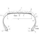
- FIG. 1 is a meridian cross-sectional view showing a pneumatic tire according to an embodiment of the present invention.
- 2 is a cross-sectional view showing a laminate comprising a film layer and a base rubber layer in the pneumatic tire of FIG.
- FIG. 3 is a cross-sectional view showing a process of forming openings in the film layer.
- FIG. 4 is a cross-sectional view showing a modified example of a laminate comprising a film layer and a base rubber layer.
- FIG. 5 is a plan view showing an example of an information display object depicted by the opening.
- FIG. 6 is a plan view showing another example of the information display object depicted by the opening.
- FIG. 7 is a plan view showing another example of the information display object depicted by the opening.
- the pneumatic tire of the present embodiment includes a tread portion 1 that extends in the tire circumferential direction and has an annular shape, and a pair of sidewall portions 2, 2 disposed on both sides of the tread portion 1. And a pair of bead portions 3 and 3 disposed inside the sidewall portion 2 in the tire radial direction.
- the carcass layer 4 is mounted between the pair of bead portions 3 and 3.
- the carcass layer 4 includes a plurality of reinforcing cords extending in the tire radial direction, and is folded from the inside of the tire to the outside around the bead core 5 disposed in each bead portion 3.
- a bead filler 6 made of a rubber composition having a triangular cross-section is disposed on the outer periphery of the bead core 5.
- a plurality of belt layers 7 are embedded on the outer peripheral side of the carcass layer 4 in the tread portion 1.
- These belt layers 7 include a plurality of reinforcing cords inclined with respect to the tire circumferential direction, and are arranged so that the reinforcing cords cross each other between the layers.
- the inclination angle of the reinforcing cord with respect to the tire circumferential direction is set, for example, in the range of 10 ° to 40 °.
- a steel cord is preferably used as the reinforcing cord of the belt layer 7.
- At least one belt cover layer 8 in which reinforcing cords are arranged at an angle of, for example, 5 ° or less with respect to the tire circumferential direction is disposed on the outer peripheral side of the belt layer 7. Yes.
- an organic fiber cord such as nylon or aramid is preferably used.
- An inner liner layer 9 is disposed along the carcass layer 4 on the tire inner wall.
- tire reinforcement structure mentioned above shows the typical example in a pneumatic tire, it is not limited to this.
- the inner liner layer 9 includes two film layers 11 and 12 disposed on the tire surface and a base rubber layer disposed below the film layers 11 and 12. 14 and the laminated body 10 (10A).
- the base rubber layer 14 is a tie rubber layer interposed between the carcass layer 4 and the film layers 11 and 12.
- the outer wall of the sidewall portion 2 includes a laminate including two film layers 11 and 12 disposed on the tire surface and a base rubber layer 14 disposed below the film layers 11 and 12.
- a body 10 (10B) is added.
- the base rubber layer 14 is a tie rubber layer interposed between the rubber layer adjacent to the laminated body 10B and the film layers 11 and 12.
- the above-described film layers 11 and 12 are both made of a thermoplastic resin or a thermoplastic elastomer composition obtained by blending a thermoplastic resin and an elastomer.
- the thicknesses of the film layers 11 and 12 are not particularly limited, but are desirably set in the range of 10 ⁇ m to 200 ⁇ m, for example.
- the outermost film layer 11 exposed on the tire surface is colored in a color different from the film layer 12 adjacent to the lower side thereof.
- a plurality of openings 15 are formed in the outermost film layer 11 by laser processing, and the film layer 12 adjacent to the lower side of the outermost film layer 11 is exposed through the openings 15.
- the pneumatic tire provided with the laminated body 10 including the film layers 11 and 12 and the base rubber layer 14 laminated as described above is vulcanized. After that, as shown in FIG. 3, a plurality of openings are formed in the outermost film layer 11 by irradiating the film layer 11 with laser light 22 from the processing head 21 of the laser irradiation apparatus and removing the irradiated portion. 15 is formed, and the film layer 12 is exposed through these openings 15.
- the irradiation of the laser beam 22 may be performed continuously while moving the processing head 21, or may be performed intermittently while moving the processing head 21.
- the depth of the opening 15 to be formed can be adjusted as appropriate.
- the laser for example, an infrared laser, a CO 2 (carbon dioxide) laser, and a YAG laser can be used.
- the use of a CO 2 (carbon dioxide) laser is preferable in terms of good workability and controllability.
- the processing width (line width) of processing by laser light is preferably set in the range of 0.2 mm to 1.0 mm, for example.
- the pneumatic tire obtained as described above includes the laminate 10 including the film layers 11 and 12 and the base rubber layer 14 disposed on the tire surface, and is a film layer made of a thermoplastic resin or a thermoplastic elastomer composition.
- 11 is formed with a plurality of openings 15 by laser processing, and the film layer 12 is exposed through these openings 15, so that arbitrary information can be displayed based on the shape or arrangement of the openings 15 It is.
- the outermost film layer 11 is colored in a color different from that of the film layer 12 adjacent to the lower side, the visibility of displayed information is excellent.
- the laminate 10 can be formed integrally with the tire, unlike the conventional case of sticking a seal, the information display object is prevented from dropping and the necessary information is lengthened. Can be displayed reliably over a period of time.
- the laminate 10 includes a plurality of film layers 11 and 12, and the film layer 12 is exposed through the opening 15. Therefore, the film layer 12 is different from the outermost film layer 11.
- the color to be exposed through the opening 15 can be arbitrarily selected.
- the laminated body 10 from the one-layer film layer 11 arrange
- the outermost film layer 11 exposed on the tire surface is colored in a different color from the underlying rubber layer 14 adjacent to the lower side, and a plurality of openings 15 are formed in the outermost film layer 11 by laser processing.
- the base rubber layer 14 adjacent to the lower side of the outermost film layer 11 is exposed through the openings 15.
- the laminate 10 is disposed on the inner wall of the tire or the outer wall of the sidewall portion 2.
- the laminated body 10 is disposed at least in the belt inner region X corresponding to the belt layer 7 embedded in the tread portion 1, and the opening 15 is formed in the belt inner region X. good.
- the opening 15 is preferably arranged in the belt inner region X of the tire inner wall, but the opening 15 can be formed on the inner wall of the sidewall portion 2 or the bead portion 3.
- the laminated body 10 may be formed in the whole region of a tire inner wall, it can also be formed selectively only in the belt inner region X.
- FIGS. 5 to 7 each illustrate information display objects depicted by openings.
- the opening 15 can form an information display element 17 composed of characters, figures, symbols, or numbers.
- the opening 15 can constitute an information display object 18 including a company logo, a tire brand, a barcode, a tire size, manufacturing information, usage conditions, or usage precautions.
- these information display objects 18 are displayed based on the openings 15, excellent visibility can be secured for the information display objects 18, and the information display objects 18 can be prevented from falling off.
- thermoplastic resin used for the film layer in the present invention or a thermoplastic elastomer composition obtained by blending a thermoplastic resin and an elastomer will be described.
- thermoplastic resin used in the present invention examples include polyamide resins [for example, nylon 6 (N6), nylon 66 (N66), nylon 46 (N46), nylon 11 (N11), nylon 12 (N12), Nylon 610 (N610), Nylon 612 (N612), Nylon 6/66 copolymer (N6 / 66), Nylon 6/66/610 copolymer (N6 / 66/610), Nylon MXD6 (MXD6), Nylon 6T , Nylon 6 / 6T copolymer, nylon 66 / PP copolymer, nylon 66 / PPS copolymer] and their N-alkoxyalkylated products (for example, methoxymethylated product of nylon 6, nylon 6/610 copolymer) Methoxymethylated product, nylon 612 methoxymethylated product], polyester resin [for example, Ribbylene terephthalate (PBT), polyethylene terephthalate (PET), polyethylene isophthalate (PEI), PET / PE
- Examples of the elastomer used in the present invention include diene rubber and hydrogenated products thereof [for example, natural rubber (NR), isoprene rubber (IR), epoxidized natural rubber, styrene butadiene rubber (SBR), butadiene rubber (BR, high cis BR and low cis BR), nitrile rubber (NBR), hydrogenated NBR, hydrogenated SBR], olefin rubber [for example, ethylene propylene rubber (EPDM, EPM), maleic acid modified ethylene propylene rubber (M- EPM), butyl rubber (IIR), isobutylene and aromatic vinyl or diene monomer copolymer, acrylic rubber (ACM), ionomer], halogen-containing rubber [for example, Br-IIR, CI-IIR, isobutylene paramethylstyrene copolymer Combined bromide (Br-IPMS), chloroprene rubber (C ), Hydrin rubber (CHR), chlorosulf
- compatibility between the specific thermoplastic resin and the elastomer described above is different, they can be made compatible by using an appropriate compatibilizing agent as the third component.
- an appropriate compatibilizing agent By mixing the compatibilizer with the blend system, the interfacial tension between the thermoplastic resin and the elastomer decreases, and as a result, the diameter of the rubber particles forming the dispersed phase becomes finer. It will be expressed effectively.
- a compatibilizing agent generally includes a copolymer having a structure of both or one of a thermoplastic resin and an elastomer, or an epoxy group, a carbonyl group, a halogen group, and an amino group that can react with the thermoplastic resin or elastomer.
- a copolymer having an oxazoline group, a hydroxyl group and the like can be taken.
- These may be selected according to the type of thermoplastic resin and elastomer to be mixed, but those commonly used include styrene / ethylene butylene block copolymer (SEBS) and its maleic acid modified product, EPDM, EPM, EPDM / styrene or EPDM / acrylonitrile graft copolymer and its modified maleic acid, styrene / maleic acid copolymer, reactive phenoxin and the like can be mentioned.
- SEBS styrene / ethylene butylene block copolymer
- the amount of the compatibilizing agent is not particularly limited, but is preferably 0.5 to 10 parts by weight with respect to 100 parts by weight of the polymer component (the total of the thermoplastic resin and the elastomer).
- the composition ratio between the specific thermoplastic resin and the elastomer is not particularly limited, and is appropriately determined so as to have a structure in which the elastomer is dispersed as a discontinuous phase in the thermoplastic resin matrix.
- the preferred range is 90/10 to 15/85 by weight.
- the thermoplastic resin and the thermoplastic elastomer composition can be mixed with other polymers such as the above-described compatibilizer within a range not damaging the necessary characteristics.
- the purpose of mixing other polymers is to improve the compatibility between the thermoplastic resin and the elastomer, to improve the molding processability of the material, to improve the heat resistance, to reduce the cost, etc.
- the material that can be used include polyethylene (PE), polypropylene (PP), polystyrene (PS), ABS, SBS, and polycarbonate (PC).
- fillers (calcium carbonate, titanium oxide, alumina, etc.) generally incorporated into polymer blends, reinforcing agents such as carbon black and white carbon, softeners, plasticizers, processing aids, pigments, dyes, and aging An inhibitor or the like can be arbitrarily blended as long as necessary characteristics are not impaired.
- the elastomer can be dynamically vulcanized when mixed with the thermoplastic resin.
- the vulcanizing agent, vulcanization aid, vulcanization conditions (temperature, time), and the like in the case of dynamic vulcanization may be appropriately determined according to the composition of the elastomer to be added, and are not particularly limited.
- a general rubber vulcanizing agent (crosslinking agent) can be used as the vulcanizing agent.
- sulfur vulcanizing agents include powdered sulfur, precipitated sulfur, highly dispersible sulfur, surface-treated sulfur, insoluble sulfur, dimorpholine disulfide, alkylphenol disulfide, and the like. 4 phr [In the present specification, “phr” refers to parts by weight per 100 parts by weight of the elastomer component. same as below. ] Can be used.
- Organic peroxide vulcanizing agents include benzoyl peroxide, t-butyl hydroperoxide, 2,4-dichlorobenzoyl peroxide, 2,5-dimethyl-2,5-di (t-butyl peroxide). Examples thereof include oxy) hexane, 2,5-dimethylhexane-2,5-di (peroxylbenzoate), and about 1 to 20 phr can be used.
- examples of the phenol resin vulcanizing agent include bromides of alkyl phenol resins, mixed crosslinking systems containing halogen donors such as tin chloride and chloroprene, and alkyl phenol resins. For example, about 1 to 20 phr is used. Can do.
- zinc white about 5 phr
- magnesium oxide about 4 phr
- risurge about 10 to 20 phr
- p-quinonedioxime p-dibenzoylquinonedioxime
- tetrachloro-p-benzoquinone poly-p- Examples include dinitrosobenzene (about 2 to 10 phr) and methylenedianiline (about 0.2 to 10 phr).
- a vulcanization accelerator as needed.
- the vulcanization accelerator include general vulcanization accelerators such as aldehyde / ammonia, guanidine, thiazole, sulfenamide, thiuram, dithioate, and thiourea, such as 0.5 to About 2 phr can be used.
- aldehyde / ammonia vulcanization accelerator hexamethylenetetramine and the like
- guanidinium vulcanization accelerator diphenyl guanidine, etc.
- thiazole vulcanization accelerator dibenzothiazyl disulfide (DM), 2-mercaptobenzothiazole and its Zn salt, cyclohexylamine salt, etc.
- sulfenamide vulcanization accelerators include cyclohexylbenzothiazylsulfenamide (CBS), N-oxydiethylenebenzothiazyl-2-
- thiuram vulcanization accelerators such as sulfenamide, Nt-butyl-2-benzothiazole sulfenamide, and 2- (thymolpolynyldithio) benzothiazole include tetramethylthiuram disulfide (TMTD), tetraethyl Thiuram disulfide (TMTD), te
- a vulcanization accelerating aid general rubber auxiliaries can be used together.
- zinc white (about 5 phr) stearic acid, oleic acid and Zn salts thereof (about 2 to 4 phr) Etc. can be used.
- a method for producing a thermoplastic elastomer composition includes a thermoplastic resin in which a thermoplastic resin and an elastomer (unvulcanized in the case of rubber) are melt-kneaded in advance using a twin-screw kneading extruder or the like to form a continuous phase (matrix). By dispersing the elastomer as a dispersed phase (domain) in it. When the elastomer is vulcanized, a vulcanizing agent may be added under kneading to dynamically vulcanize the elastomer.
- various compounding agents for the thermoplastic resin or elastomer may be added during the kneading, but it is preferable to mix them in advance before kneading.
- the kneading machine used for kneading the thermoplastic resin and the elastomer is not particularly limited, and a screw extruder, a kneader, a Banbury mixer, a biaxial kneading extruder, or the like can be used.
- a twin-screw kneading extruder for kneading the thermoplastic resin and the elastomer and for dynamic vulcanization of the elastomer.
- two or more types of kneaders may be used and kneaded sequentially.
- the temperature may be equal to or higher than the temperature at which the thermoplastic resin melts.
- the shear rate during kneading is preferably 1000 to 7500 sec ⁇ 1 .
- the entire kneading time is from 30 seconds to 10 minutes, and when a vulcanizing agent is added, the vulcanization time after addition is preferably from 15 seconds to 5 minutes.
- the polymer composition produced by the above method may be formed into a desired shape by a general thermoplastic resin molding method such as injection molding or extrusion molding.
- thermoplastic elastomer composition thus obtained has a structure in which an elastomer is dispersed as a discontinuous phase in a matrix of a thermoplastic resin.
- the film layer can be provided with sufficient flexibility and sufficient rigidity due to the effect of the resin layer as a continuous phase, and at the time of molding, regardless of the amount of elastomer, Equivalent moldability can be obtained.
- the Young's modulus in the standard atmosphere of the thermoplastic resin and the thermoplastic elastomer composition as defined by JIS K7100 is not particularly limited, but is preferably 1 to 500 MPa, more preferably 50 to 500 MPa.
- thermoplastic resin or thermoplastic elastomer composition can be formed into a sheet or film and used alone, but an adhesive layer may be laminated in order to enhance the adhesion to the adjacent rubber.
- adhesive polymer constituting the adhesive layer include ultrahigh molecular weight polyethylene (UHMWPE), ethylene ethyl acrylate copolymer (EEA), ethylene methyl acrylate resin (EMA) having a molecular weight of 1 million or more, preferably 3 million or more.
- EAA ethylene acrylic acid copolymer
- PP polypropylene
- PP polypropylene
- PP polypropylene
- PP polypropylene
- PP polypropylene
- PP polypropylene
- PP polypropylene
- PP polypropylene
- PP polypropylene
- PP polypropylene
- PP polypropylene
- PP polypropylene
- PP polypropylene
- PP polypropylene
- PP polypropylene
- PP polypropylene
- PP polypropylene
- PP polypropylene
- PP polypropylene
- PP polypropylene
- PP polypropylene
- PP polypropylene
- PP polypropylene
- PP polypropylene
- PP polypropylene
- PP polypropylene
- PP polypropylene
- PP polypropylene
- PP polypropylene
- PP polypropylene
- the tire size is 235 / 40R18 91W, and a laminated body including at least one film layer disposed on the tire surface and a base rubber layer disposed below the film layer is provided at a predetermined portion, and the film layer Is composed of a thermoplastic elastomer composition obtained by blending a thermoplastic resin and an elastomer, and a pneumatic tire colored with a color different from the layer adjacent to the outermost film layer exposed on the tire surface is added.
- a plurality of openings are formed in the outermost film layer by laser processing, and a layer adjacent to the lower side of the outermost film layer is exposed through these openings, so that the openings are letters and Tires of Examples 1 to 4 were constructed so as to constitute information display objects including symbols.
- the inner liner layer is composed of the laminate shown in FIG. 4, the outermost film layer exposed on the tire surface is white, the underlying rubber layer adjacent to the lower side is black, and the outermost layer is outermost.
- this film layer a plurality of openings are formed by laser processing, and the underlying rubber layer adjacent to the lower side of the outermost film layer is exposed through these openings.
- the laminate shown in FIG. 4 is added to the outer wall of the sidewall portion, the outermost film layer exposed on the tire surface is white, and the underlying rubber layer adjacent to the lower side is black, A plurality of openings are formed by laser processing in the outermost film layer, and a base rubber layer adjacent to the lower side of the outermost film layer is exposed through these openings.
- the inner liner layer is composed of the laminate shown in FIG. 2, the outermost film layer exposed on the tire surface is black, the film layer adjacent to the lower side is white, and the outermost film layer is outermost.
- a plurality of openings by laser processing are formed in the film layer, and the film layer adjacent to the lower side of the outermost film layer is exposed through these openings.
- the laminate shown in FIG. 2 is added to the outer wall of the sidewall portion, the outermost film layer exposed on the tire surface is black, the film layer adjacent to the lower side is white, and the outermost film layer is white.
- a plurality of openings by laser processing are formed in the outer film layer, and the film layer adjacent to the lower side of the outermost film layer is exposed through these openings.
- thermoplastic elastomer composition constituting the film layer
- a base material having the composition shown in Table 1 is prepared, and 1% by weight of titanium oxide (TiO) or 0.1% by weight of carbon black is added thereto. And white or black.
- the thickness of each film layer was about 80 ⁇ m.
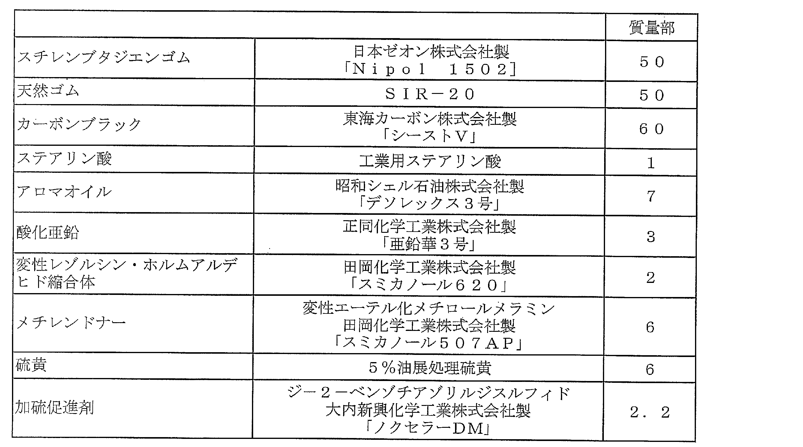
- a rubber composition having the composition shown in Table 2 was used as the tie rubber layer serving as the base rubber layer.
Landscapes
- Engineering & Computer Science (AREA)
- Mechanical Engineering (AREA)
- Tires In General (AREA)
- Tyre Moulding (AREA)
Abstract
Description

b)無水マレイン酸変性エチレン-エチルアクリレート共重合体
2 サイドウォール部
3 ビード部
10 積層体
11,12 フィルム層
14 下地ゴム層
15 開口部
17 情報表示要素
18 情報表示物
Claims (14)
- タイヤ表面に配置された少なくとも1層のフィルム層と該フィルム層の下側に配置された下地ゴム層とを含む積層体を備え、前記フィルム層を熱可塑性樹脂又は熱可塑性樹脂とエラストマーとをブレンドした熱可塑性エラストマー組成物から構成すると共に、前記積層体においてタイヤ表面に露出する最外側のフィルム層をその下側に隣接する層とは異なる色に着色し、前記最外側のフィルム層にレーザー加工による複数の開口部を形成し、これら開口部を介して前記最外側のフィルム層の下側に隣接する層を露出させたことを特徴とする空気入りタイヤ。
- 前記開口部が文字、図形、記号又は数字からなる情報表示要素を形成することを特徴とする請求項1に記載の空気入りタイヤ。
- 前記開口部が会社のロゴマーク、タイヤのブランド、バーコード、タイヤサイズ、製造情報、使用条件又は使用上の注意事項からなる情報表示物を構成することを特徴とする請求項1又は2に記載の空気入りタイヤ。
- 前記積層体が複数層のフィルム層を含み、タイヤ表面に露出する最外側のフィルム層をその下側に隣接するフィルム層とは異なる色に着色し、前記開口部を介して前記最外側のフィルム層の下側に隣接するするフィルム層を露出させたことを特徴とする請求項1~3のいずれかに記載の空気入りタイヤ。
- 前記積層体をタイヤ内壁に配置したことを特徴とする請求項1~4のいずれかに記載の空気入りタイヤ。
- 前記積層体をトレッド部に埋設されたベルト層に対応するベルト内側領域に配置し、該ベルト内側領域に前記開口部を形成したことを特徴とする請求項5に記載の空気入りタイヤ。
- 前記積層体をサイドウォール部の外壁に配置したことを特徴とする請求項1~6のいずれかに記載の空気入りタイヤ。
- タイヤ表面に配置された少なくとも1層のフィルム層と該フィルム層の下側に配置された下地ゴム層とを含む積層体を備え、前記フィルム層を熱可塑性樹脂又は熱可塑性樹脂とエラストマーとをブレンドした熱可塑性エラストマー組成物から構成すると共に、前記積層体においてタイヤ表面に露出する最外側のフィルム層をその下側に隣接する層とは異なる色に着色した空気入りタイヤを加硫した後、前記最外側のフィルム層にレーザー加工により複数の開口部を形成し、これら開口部を介して前記最外側のフィルム層の下側に隣接する層を露出させることを特徴とする空気入りタイヤの製造方法。
- 前記開口部が文字、図形、記号又は数字からなる情報表示要素を形成することを特徴とする請求項8に記載の空気入りタイヤの製造方法。
- 前記開口部が会社のロゴマーク、タイヤのブランド、バーコード、タイヤサイズ、製造情報、使用条件又は使用上の注意事項からなる情報表示物を構成することを特徴とする請求項8又は9に記載の空気入りタイヤの製造方法。
- 前記積層体が複数層のフィルム層を含み、タイヤ表面に露出する最外側のフィルム層をその下側に隣接するフィルム層とは異なる色に着色し、前記開口部を介して前記最外側のフィルム層の下側に隣接するするフィルム層を露出させることを特徴とする請求項8~10のいずれかに記載の空気入りタイヤの製造方法。
- 前記積層体をタイヤ内壁に配置したことを特徴とする請求項8~11のいずれかに記載の空気入りタイヤの製造方法。
- 前記積層体をトレッド部に埋設されたベルト層に対応するベルト内側領域に配置し、該ベルト内側領域に前記開口部を形成することを特徴とする請求項12に記載の空気入りタイヤの製造方法。
- 前記積層体をサイドウォール部の外壁に配置したことを特徴とする請求項8~13のいずれかに記載の空気入りタイヤの製造方法。
Priority Applications (3)
| Application Number | Priority Date | Filing Date | Title |
|---|---|---|---|
| DE112014002154.7T DE112014002154T5 (de) | 2013-04-25 | 2014-04-17 | Luftreifen und Verfahren zum Herstellen desselben |
| CN201480022930.5A CN105142935A (zh) | 2013-04-25 | 2014-04-17 | 充气轮胎及其制造方法 |
| US14/786,927 US20160082782A1 (en) | 2013-04-25 | 2014-04-17 | Pneumatic Tire and Method of Manufacturing Same |
Applications Claiming Priority (2)
| Application Number | Priority Date | Filing Date | Title |
|---|---|---|---|
| JP2013-092469 | 2013-04-25 | ||
| JP2013092469A JP6244649B2 (ja) | 2013-04-25 | 2013-04-25 | 空気入りタイヤ及びその製造方法 |
Publications (1)
| Publication Number | Publication Date |
|---|---|
| WO2014175155A1 true WO2014175155A1 (ja) | 2014-10-30 |
Family
ID=51791734
Family Applications (1)
| Application Number | Title | Priority Date | Filing Date |
|---|---|---|---|
| PCT/JP2014/060911 Ceased WO2014175155A1 (ja) | 2013-04-25 | 2014-04-17 | 空気入りタイヤ及びその製造方法 |
Country Status (5)
| Country | Link |
|---|---|
| US (1) | US20160082782A1 (ja) |
| JP (1) | JP6244649B2 (ja) |
| CN (1) | CN105142935A (ja) |
| DE (1) | DE112014002154T5 (ja) |
| WO (1) | WO2014175155A1 (ja) |
Cited By (1)
| Publication number | Priority date | Publication date | Assignee | Title |
|---|---|---|---|---|
| US11207926B2 (en) | 2017-10-04 | 2021-12-28 | The Yokohama Rubber Co., Ltd. | Pneumatic tire |
Families Citing this family (5)
| Publication number | Priority date | Publication date | Assignee | Title |
|---|---|---|---|---|
| WO2015030825A1 (en) * | 2013-08-30 | 2015-03-05 | Compagnie Generale Des Etablissements Michelin | Methods for forming a retreaded tire |
| DE112018005489B4 (de) * | 2017-10-04 | 2022-10-20 | The Yokohama Rubber Co., Ltd. | Luftreifen |
| US12214627B2 (en) * | 2018-09-20 | 2025-02-04 | The Yokohama Rubber Co., Ltd. | Pneumatic tire |
| FR3097166B1 (fr) * | 2019-06-13 | 2021-11-19 | Michelin & Cie | Procédé pour déposer une couche colorée et pneumatique |
| CN111792276A (zh) * | 2020-06-08 | 2020-10-20 | 湖北海特尔科技有限公司 | 具有耐高温、阻燃与耐油的橡胶输送带及其制造工艺 |
Citations (6)
| Publication number | Priority date | Publication date | Assignee | Title |
|---|---|---|---|---|
| JPH09295503A (ja) * | 1996-05-07 | 1997-11-18 | Yokohama Rubber Co Ltd:The | 空気入りタイヤおよび空気入りタイヤ−リム組立体 |
| JPH1086605A (ja) * | 1996-07-22 | 1998-04-07 | Yokohama Rubber Co Ltd:The | 空気入りタイヤ |
| JPH10222070A (ja) * | 1997-02-10 | 1998-08-21 | Bridgestone Corp | 情報記録領域付タイヤ及びこのタイヤへの表示方法 |
| JP2000025404A (ja) * | 1998-07-14 | 2000-01-25 | Yokohama Rubber Co Ltd:The | 空気入りタイヤおよび空気入りタイヤ−リム組立体 |
| JP2000075794A (ja) * | 1998-08-31 | 2000-03-14 | Bridgestone Corp | 表示ラベル、表示ラベルのマーキング方法及び装置並びにタイヤ |
| JP2011170105A (ja) * | 2010-02-18 | 2011-09-01 | Kuramoto Sangyo:Kk | 情報表示ラベル |
Family Cites Families (5)
| Publication number | Priority date | Publication date | Assignee | Title |
|---|---|---|---|---|
| JP3501417B2 (ja) * | 1994-09-26 | 2004-03-02 | 株式会社ブリヂストン | ゴム加硫成型品の情報表示方法 |
| JPH10129219A (ja) * | 1996-10-29 | 1998-05-19 | Bridgestone Corp | タイヤ情報表示用シール及びその貼付方法 |
| JPH10129220A (ja) * | 1996-10-29 | 1998-05-19 | Bridgestone Corp | タイヤ情報表示用シール及びその貼付方法 |
| CA2311960C (en) * | 1999-07-30 | 2009-12-22 | The Goodyear Tire & Rubber Company | Permanent tamper resistant bar code labels for tires |
| JP5423732B2 (ja) * | 2010-12-22 | 2014-02-19 | 横浜ゴム株式会社 | 空気入りタイヤ |
-
2013
- 2013-04-25 JP JP2013092469A patent/JP6244649B2/ja not_active Expired - Fee Related
-
2014
- 2014-04-17 WO PCT/JP2014/060911 patent/WO2014175155A1/ja not_active Ceased
- 2014-04-17 CN CN201480022930.5A patent/CN105142935A/zh active Pending
- 2014-04-17 US US14/786,927 patent/US20160082782A1/en not_active Abandoned
- 2014-04-17 DE DE112014002154.7T patent/DE112014002154T5/de not_active Withdrawn
Patent Citations (6)
| Publication number | Priority date | Publication date | Assignee | Title |
|---|---|---|---|---|
| JPH09295503A (ja) * | 1996-05-07 | 1997-11-18 | Yokohama Rubber Co Ltd:The | 空気入りタイヤおよび空気入りタイヤ−リム組立体 |
| JPH1086605A (ja) * | 1996-07-22 | 1998-04-07 | Yokohama Rubber Co Ltd:The | 空気入りタイヤ |
| JPH10222070A (ja) * | 1997-02-10 | 1998-08-21 | Bridgestone Corp | 情報記録領域付タイヤ及びこのタイヤへの表示方法 |
| JP2000025404A (ja) * | 1998-07-14 | 2000-01-25 | Yokohama Rubber Co Ltd:The | 空気入りタイヤおよび空気入りタイヤ−リム組立体 |
| JP2000075794A (ja) * | 1998-08-31 | 2000-03-14 | Bridgestone Corp | 表示ラベル、表示ラベルのマーキング方法及び装置並びにタイヤ |
| JP2011170105A (ja) * | 2010-02-18 | 2011-09-01 | Kuramoto Sangyo:Kk | 情報表示ラベル |
Cited By (1)
| Publication number | Priority date | Publication date | Assignee | Title |
|---|---|---|---|---|
| US11207926B2 (en) | 2017-10-04 | 2021-12-28 | The Yokohama Rubber Co., Ltd. | Pneumatic tire |
Also Published As
| Publication number | Publication date |
|---|---|
| US20160082782A1 (en) | 2016-03-24 |
| JP6244649B2 (ja) | 2017-12-13 |
| CN105142935A (zh) | 2015-12-09 |
| DE112014002154T5 (de) | 2015-12-31 |
| JP2014213717A (ja) | 2014-11-17 |
Similar Documents
| Publication | Publication Date | Title |
|---|---|---|
| JP4346666B2 (ja) | 空気入りタイヤ | |
| JP4442700B2 (ja) | 空気入りタイヤ及びその製造方法 | |
| JP2009269446A (ja) | 空気入りタイヤおよびその製造方法 | |
| JP6244649B2 (ja) | 空気入りタイヤ及びその製造方法 | |
| JPH1035232A (ja) | 空気入りタイヤ | |
| JP2010125891A (ja) | 空気入りタイヤ | |
| JP2010111351A (ja) | 空気入りタイヤ | |
| JP6454457B2 (ja) | 空気入りタイヤ | |
| JP6115287B2 (ja) | 空気入りタイヤ及びその製造方法 | |
| JP5354057B2 (ja) | 空気入りタイヤ | |
| JP5299539B1 (ja) | 空気入りタイヤ | |
| JP2010125890A (ja) | 空気入りタイヤ | |
| JP6281194B2 (ja) | 空気入りタイヤ | |
| JP2009208734A (ja) | 空気入りタイヤ | |
| JP5262278B2 (ja) | 空気入りタイヤ | |
| JPWO2014087944A1 (ja) | 空気入りタイヤ | |
| JP7180151B2 (ja) | 空気入りタイヤ | |
| JP5999104B2 (ja) | 空気入りタイヤ | |
| JP6019628B2 (ja) | 空気入りタイヤ | |
| JP2010132227A (ja) | 空気入りタイヤ | |
| JP2007050722A (ja) | 空気入りタイヤ | |
| JPWO2014087942A1 (ja) | 空気入りタイヤ | |
| JP2009214630A (ja) | タイヤ・ホイール組立体、ホイール及び空気入りタイヤ |
Legal Events
| Date | Code | Title | Description |
|---|---|---|---|
| WWE | Wipo information: entry into national phase |
Ref document number: 201480022930.5 Country of ref document: CN |
|
| 121 | Ep: the epo has been informed by wipo that ep was designated in this application |
Ref document number: 14787770 Country of ref document: EP Kind code of ref document: A1 |
|
| WWE | Wipo information: entry into national phase |
Ref document number: 14786927 Country of ref document: US |
|
| WWE | Wipo information: entry into national phase |
Ref document number: 112014002154 Country of ref document: DE Ref document number: 1120140021547 Country of ref document: DE |
|
| 122 | Ep: pct application non-entry in european phase |
Ref document number: 14787770 Country of ref document: EP Kind code of ref document: A1 |