WO2014162629A1 - エアゾール容器用固定盤 - Google Patents
エアゾール容器用固定盤 Download PDFInfo
- Publication number
- WO2014162629A1 WO2014162629A1 PCT/JP2013/080702 JP2013080702W WO2014162629A1 WO 2014162629 A1 WO2014162629 A1 WO 2014162629A1 JP 2013080702 W JP2013080702 W JP 2013080702W WO 2014162629 A1 WO2014162629 A1 WO 2014162629A1
- Authority
- WO
- WIPO (PCT)
- Prior art keywords
- wall
- aerosol container
- cover member
- aerosol
- fixed plate
- Prior art date
- Legal status (The legal status is an assumption and is not a legal conclusion. Google has not performed a legal analysis and makes no representation as to the accuracy of the status listed.)
- Ceased
Links
Images


Classifications
-
- B—PERFORMING OPERATIONS; TRANSPORTING
- B05—SPRAYING OR ATOMISING IN GENERAL; APPLYING FLUENT MATERIALS TO SURFACES, IN GENERAL
- B05B—SPRAYING APPARATUS; ATOMISING APPARATUS; NOZZLES
- B05B11/00—Single-unit hand-held apparatus in which flow of contents is produced by the muscular force of the operator at the moment of use
- B05B11/0005—Components or details
- B05B11/0078—Arrangements for separately storing several components
-
- B—PERFORMING OPERATIONS; TRANSPORTING
- B65—CONVEYING; PACKING; STORING; HANDLING THIN OR FILAMENTARY MATERIAL
- B65D—CONTAINERS FOR STORAGE OR TRANSPORT OF ARTICLES OR MATERIALS, e.g. BAGS, BARRELS, BOTTLES, BOXES, CANS, CARTONS, CRATES, DRUMS, JARS, TANKS, HOPPERS, FORWARDING CONTAINERS; ACCESSORIES, CLOSURES, OR FITTINGS THEREFOR; PACKAGING ELEMENTS; PACKAGES
- B65D83/00—Containers or packages with special means for dispensing contents
- B65D83/14—Containers for dispensing liquid or semi-liquid contents by internal gaseous pressure, i.e. aerosol containers comprising propellant
- B65D83/16—Actuating means
- B65D83/20—Actuator caps
- B65D83/206—Actuator caps comprising cantilevered actuating elements, e.g. levers pivoting about living hinges
-
- B—PERFORMING OPERATIONS; TRANSPORTING
- B65—CONVEYING; PACKING; STORING; HANDLING THIN OR FILAMENTARY MATERIAL
- B65D—CONTAINERS FOR STORAGE OR TRANSPORT OF ARTICLES OR MATERIALS, e.g. BAGS, BARRELS, BOTTLES, BOXES, CANS, CARTONS, CRATES, DRUMS, JARS, TANKS, HOPPERS, FORWARDING CONTAINERS; ACCESSORIES, CLOSURES, OR FITTINGS THEREFOR; PACKAGING ELEMENTS; PACKAGES
- B65D83/00—Containers or packages with special means for dispensing contents
- B65D83/14—Containers for dispensing liquid or semi-liquid contents by internal gaseous pressure, i.e. aerosol containers comprising propellant
- B65D83/68—Dispensing two or more contents
-
- B—PERFORMING OPERATIONS; TRANSPORTING
- B65—CONVEYING; PACKING; STORING; HANDLING THIN OR FILAMENTARY MATERIAL
- B65D—CONTAINERS FOR STORAGE OR TRANSPORT OF ARTICLES OR MATERIALS, e.g. BAGS, BARRELS, BOTTLES, BOXES, CANS, CARTONS, CRATES, DRUMS, JARS, TANKS, HOPPERS, FORWARDING CONTAINERS; ACCESSORIES, CLOSURES, OR FITTINGS THEREFOR; PACKAGING ELEMENTS; PACKAGES
- B65D83/00—Containers or packages with special means for dispensing contents
- B65D83/14—Containers for dispensing liquid or semi-liquid contents by internal gaseous pressure, i.e. aerosol containers comprising propellant
- B65D83/40—Closure caps
Definitions
- the present invention relates to an aerosol container fixing plate that engages and holds a cover member that is mounted on an aerosol container and covers a mounting cup of the container, and in particular, contains two types of contents separately and each content. It is related with what is attached to the aerosol container which has a total of two stems which discharge.
- a container for storing a two-component hair dye or hairdressing agent has a fixed platen that holds cylindrical aerosol containers side by side, and two connecting parts that connect to the stems of each aerosol container.
- a double-type aerosol container is known that includes a nozzle that discharges the contents contained in each container from one dispensing cylinder, and a cover member that includes an operation unit that presses the nozzle (for example, a patent). Reference 1).
- the cross-sectional shape of the whole pair of containers becomes a track shape
- the shape of the fixed plate and the cover member attached to the container also becomes a track shape.
- the positioning can be performed by checking only the front-rear direction with respect to the container.
- An object of the present invention is to solve such a problem.
- the object of the present invention is to reliably and easily attach an aerosol container having two stems, and various cover members.
- a new aerosol container fixing plate that can be installed is proposed.
- the present invention is an aerosol container fixing plate that is attached to an aerosol container having two stems and engages and holds a cover member that covers and hides the mounting cup of the container, An outer wall that covers the mounting cup leaving an opening that exposes the two stems, abuts against the upper surface of the annular edge of the mounting cup, and a cylindrical wall that is integrally connected to the lower surface of the outer wall and surrounds the annular edge; An engagement claw provided on the inner peripheral surface of the cylindrical wall and engaged with the annular edge to prevent the fixing plate from being pulled out, In the opening, the two stems collectively projecting from the mounting cup, and the cross-sectional shape of the projecting portion having a long side and a short side is an inner peripheral surface shape along the outer peripheral surface thereof. It is a fixed plate for aerosol containers provided with walls.
- the inner peripheral surface shape of the positioning wall is preferably a rectangular shape, a track shape, or an elliptical shape.
- the positioning wall includes a thin tongue piece extending downward at the edge on the long side.
- the outer wall includes a pair of outer ribs at a position sandwiching the pair of inner ribs with respect to the pair of inner ribs provided on both sides of the engagement piece of the cover member.
- the outer wall includes a concave portion or a convex portion that fits into at least one convex portion or concave portion provided in the cover member when the cover member is attached.
- the concave portion or the convex portion of the outer wall is provided at the front and the rear of the outer wall corresponding to the convex portion or the concave portion of the cover member, respectively, and the number of the concave portions or the convex portions provided at the front is provided at the rear or It is preferable to provide a different number with respect to the number of convex portions.
- the fixing plate is covered with the mounting cup leaving an opening for exposing two stems, an outer wall contacting the upper surface of the annular edge of the mounting cup, a cylindrical wall integrally connected to the lower surface of the outer wall and surrounding the annular edge, and a cylinder
- An engaging claw that is provided on the inner peripheral surface of the wall and that engages with the annular edge is provided, and the two stems are collectively projected into the opening from the mounting cup and have a different cross-sectional shape having a long side and a short side. Since the positioning wall having the inner peripheral surface shape along the outer peripheral surface is provided for the projecting portion having the shape, the positional deviation with respect to the container is effectively prevented, and the retaining portion can be securely held. Moreover, rotation of the stationary platen relative to the aerosol container (rotation around the axis of the container) can be prevented.
- the shape becomes simple, so that the manufacturing cost for forming these does not increase.
- the positioning wall is provided with a thin tongue that extends downward at the edge on the long side, when the fixed platen and the aerosol container are facing each other, the tip of the thin tongue is at the lower end of the protrusion.
- the fixed platen will be lowered to the abutting height, but when the directions are shifted from each other, the tip of the thin tongue piece abuts the upper surface of the protruding portion and is positioned higher than the predetermined height. Therefore, it is possible to determine whether or not the directions of both are in accordance with the difference in the height of the fixed platen. This makes assembly work easier
- the concave or convex portion of the outer wall is provided in front and rear of the outer wall in correspondence with the convex or concave portion of the cover member, respectively, and the number of concave or convex portions provided in the front is provided in the rear.
- the direction of the cover member in the front-rear direction can be known by using the difference in the number, and the assembling work becomes easy.
- FIG. 2 is an enlarged cross-sectional view of a main part along AA shown in FIG.
- FIG. 2 is an enlarged half sectional view of an essential part along BB shown in FIG. 1A, and shows a state in which an overcap is further attached to the state of FIG. 1A is a plan view
- FIG. 1B is a half sectional view taken along the line CC of FIG. 1A
- FIG. 1C is taken along the line DD of FIG. It is sectional drawing
- (d) is a bottom view.
- 1A is a plan view
- FIG. 1B is a half sectional view taken along line EE in FIG. 1A
- FIG. 1C is taken along line FF in FIG.
- FIG. 1A is a bottom view of the lower cover shown in FIG. 1
- FIG. 5B is a view taken in the direction of arrow G in FIG. 1A is a plan view
- FIG. 1B is a cross-sectional view taken along line HH in FIG. 1A
- FIG. 1C is a half view taken along line II in FIG.
- 1A is a bottom view
- FIG. 7B is an arrow view along arrow J in FIG. 7A
- FIG. 7C is an arrow K in FIG.
- FIG. 1A is a plan view
- FIG. 1B is a cross-sectional view taken along line LL in FIG. 1A
- FIG. 1C is a cross-sectional view taken along line M- in FIG. It is a half sectional view in alignment with M
- (d) is a bottom view.
- 2A is a plan view
- FIG. 2B is a half sectional view taken along line NN in FIG. 2C
- FIG. 2C is taken along line OO in FIG. It is sectional drawing.
- 2A is a bottom view of the overcap shown in FIG. 2
- FIG. 10B is an arrow view along the arrow P in FIG. FIG.
- FIG. 3 is an enlarged cross-sectional view of a main part illustrating a state in which different types of cover members, nozzles, and overcaps are attached to the state of FIG. 2 according to FIG. 2. It is a principal part expanded half sectional view which shows the state of FIG. 12 according to FIG. It is a top view of the cover member shown in FIG. FIG. 3 is an enlarged cross-sectional view of a main part of a second embodiment of the fixed plate for an aerosol container according to the present invention, showing a state in which different types of cover members and nozzles are attached to the state of FIG. 2 according to FIG. 2. . It is a principal part expanded half sectional view which shows the state of FIG. 15 according to FIG. FIG.
- FIG. 5 is an enlarged cross-sectional view of a main part of a third embodiment of an aerosol container fixing plate according to the present invention, showing a state in which different types of cover members and nozzles are attached to the state of FIG. 2 according to FIG. 2. . It is a principal part expanded half sectional view which shows the state of FIG. 17 according to FIG.
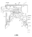
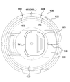
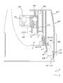
- FIG. 1 shows a first embodiment of a fixed plate for an aerosol container according to the present invention in a state where it is mounted on a container
- (a) is a plan view
- (b) is a side view
- FIG. FIG. 3 is an enlarged cross-sectional view of a main part along AA shown in FIG. 1 (a)
- FIG. 3 is an enlarged half-sectional view of a main part along BB shown in FIG. 1 (a).
- 1A is a plan view
- FIG. 1B is a half sectional view taken along the line CC in FIG. 1A
- FIG. 1C is a cross-sectional view taken along the line DD in FIG.
- FIG. 5D is a bottom view
- FIG. 5 is a plan view of the lower cover shown in FIG. 1
- FIG. 5B is a plan view of FIG.
- FIG. 6C is a cross-sectional view taken along the line FF of FIG. 6A
- FIG. 6 is a bottom view of the lower cover shown in FIG. 1
- FIG. ) Is an arrow view along the arrow G in FIG. 7A is a plan view of the upper cover shown in FIG. 1
- FIG. 7B is a cross-sectional view taken along line HH in FIG. 7A
- FIGS. 8A and 8B are half sectional views taken along the line II
- FIG. 8A is a bottom view of the upper cover shown in FIG. 1, and FIG.
- FIG. 8B is a view taken along an arrow J in FIG.
- FIG. 9C is an arrow view along arrow K in FIG. 7A
- FIG. 9 is a plan view of the state of the nozzle shown in FIG. 1 before bending
- FIG. , (B) is a cross-sectional view taken along line LL in (a)
- (c) is a half cross-sectional view taken along line MM in (a)
- (d) is a bottom view
- FIG. FIG. 2A is a plan view of the overcap shown in FIG. 2
- FIG. 2B is a half sectional view taken along line NN in FIG. 2A
- FIG. FIG. 11 is a cross-sectional view taken along the line A in FIG.
- Per over bar cap (a) is a bottom view, is an arrow view along the arrow P of (b) FIGS 10 (a).
- the front is the exit side of the extraction tube provided in the nozzle, and the rear is the opposite side to the front along the axis of the extraction tube.
- a side is the left-right direction at the time of seeing a container toward the back from the front.
- reference numeral 10A denotes a first embodiment of an aerosol container fixing plate according to the present invention
- reference numeral 2 denotes an aerosol container on which the fixing plate 10A is mounted.
- Reference numeral 20A is a lower cover
- reference numeral 30A is an upper cover
- reference numeral 40A is a nozzle
- reference numeral 50A is an overcap (overcap 50A is omitted in FIG. 1).
- the lower cover 20A and the upper cover 30A constitute a cover member 60A.
- the aerosol container 2 is formed by winding the outer edge of a mounting cup 4 made of metal, for example, on a bottomed cylindrical container body 3 made of metal, for example. (It becomes part 5) which is fixed, and two types of contents are separately accommodated inside.
- the aerosol container 2 has a total of two stems 6 connected to the storage spaces for the respective contents.
- the mounting cup 4 there are two protrusions 7 that are track-shaped in plan view.
- the stem 6 protrudes in a lump. Note that the shape of the projection 7 in plan view may be rectangular or elliptical.
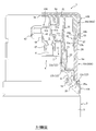
- the fixed plate 10 ⁇ / b> A includes an outer wall 12 that covers the mounting cup 4 leaving an opening 11 for exposing the two stems 6 and abuts against the upper surface of the annular edge 5.
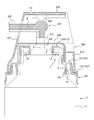
- the outer wall 12 extends from the lower end of the top step 12a in the radial direction to the outer side in the top cylindrical shape having a substantially circular shape in plan view.
- an intermediate step 12b that hangs down from the outer edge, and a lower step 12c that extends radially outward from the lower end of the intermediate step 12b and hangs down from the outer edge.
- the center part of the upper step part 12a is equipped with the inner peripheral wall 12d which forms the opening 11 inside.
- the opening 11 has a deformed rectangular shape with a short side in an arc shape and a long side in a straight line shape in a plan view, and the long side is positioned forward and backward. It has become.
- the long side of the opening 11 extends long, and a part of the inner peripheral wall 12d is integrated with the peripheral wall of the upper step portion 12a (see FIG. 4B).
- a positioning wall 13 having a track-like inner peripheral surface shape in plan view as shown in FIG. Is provided.
- the shape of the inner peripheral surface of the positioning wall 13 corresponds to the protrusion 7 of the aerosol container 2, and a rectangular or elliptical shape can be selected according to the shape of the protrusion 7.
- Thin edge portions 14 extending downward are provided on the edge of the long side of the positioning wall 13 (two in total in the present embodiment).
- the upper step portion 12a is provided with slit-like concave portions 15, and in this embodiment, the number of the concave portions 15 provided in the front is different from the number of the concave portions 15 provided in the rear in FIG.
- FIG. 4C a cylindrical wall 16 extending downward is provided on the back surface of the intermediate step portion 12b, and a claw portion (engaging claw) is provided on the inner peripheral surface of the cylindrical wall 16.
- a total of three 16a are provided at equal intervals in the circumferential direction.
- a total of two holes (first engagement holes) 17 penetrating the front and back are provided at the boundary between the intermediate step portion 12b and the lower step portion 12c as shown in FIG. 4A. Further, as shown in FIG.
- a plurality of reinforcing ribs 18a whose longitudinal cross-sectional shape is triangular are provided at the boundary between the intermediate step 12b and the lower step 12c (a total of ten in this embodiment).
- a pair of small ribs (outer ribs) 18b having a height lower than that of the reinforcing rib 18a are provided on both sides of the first engagement hole 17.
- the reinforcing ribs 18c that connect the inner surface of the peripheral wall of the upper step portion 12a and the positioning wall 13 (total 6 in this embodiment).
- a reinforcing wall 18d (four in total in the present embodiment) that connects the inner peripheral wall 12d and the inner peripheral wall surface of the upper step portion 12a.
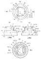
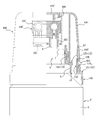
- the lower cover 20A has a substantially disk shape and a rear part thereof outward in the radial direction in plan view.
- a ceiling wall 21 having a shape projecting toward the end (the projecting portion is referred to as a projecting portion 21a) and a peripheral wall 22 connected to the edge of the top wall 21 are provided.
- the peripheral wall 22 is connected to the outer peripheral wall 24 via a connecting wall 23 that extends in the horizontal direction at a position lower than the top wall 21 at the lower end except for the rear.
- the top wall 21 includes a stepped portion 21b at the front and the rear, and a pair of upper peripheral walls 21c at the side.
- the central portion of the top wall 21 is provided with a deformed rectangular opening 21d in which the long side is positioned forward and backward in plan view, the short side is arcuate, and the long side is linear. .
- a pair of first engagement pieces 25 extending downward are provided on the side of the outer peripheral wall 24, and the first engagement pieces 25 are radially outward.
- the claw part 25a which faces is provided.
- a pair of pressing portions 26 connected to each other via a thin-walled hinge ha are provided in the middle in the vertical direction on the side of the outer peripheral wall 24, and a pair of holes that penetrate the front and back of the outer peripheral wall 24 (first 2 engaging holes) 27 are provided.
- an inclined portion 24 a is provided on the inner peripheral surface of the outer peripheral wall 24 above the second engagement hole 27.
- a convex portion (cover convex portion) 24 b (in this embodiment, as shown in FIG. 5A) extending laterally above the second engagement hole 27 on each side. A total of four), one on the front and one on the rear.
- the upper cover 30A has a substantially disk shape in plan view and a notch 31a at the rear part thereof. And a peripheral wall 32 connected to the edge of the top wall 31.
- the peripheral wall 32 is provided with a notch 32a on the lower side in front (see FIG. 8B).
- the peripheral wall 32 includes a second engagement piece 33 on each side, and the second engagement piece 33 includes a claw portion 33b facing radially outward and extends downward from the claw portion 33b.
- a pressed receiving portion 33a is provided. Further, as shown in FIG.
- the operation portion 34 is connected to the cutout portion 31a of the top wall 31 via a thin-walled hinge hb and discharges contents from the nozzle 40 by pressing downward.
- the upper surface of the operation unit 34 is located substantially on the same plane as the upper surface of the top wall 31, but the upper surface position of the operation unit 34 is below the upper surface of the top wall 31. Alternatively, it may be above the top surface of the top wall 31 so that the nozzle 40 is not pushed in when the overcap 50 is attached.
- the upper surface of the operation part 34 is flat, in order to improve finger contact, the center part may be curved downward.
- an inner peripheral wall 35 is provided on the back surface of the top wall 31 as shown in FIG.
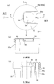
- the nozzle 40A is formed by integrally connecting an upper member 41 and a lower member 45 via a thin hinge hc, and is bent along the hinge hc. 2 and FIG. 3 are obtained.
- the upper member 41 has a top wall 41a that is elliptical in plan view, a peripheral wall 41b that is connected to the edge of the top wall 41a, and a lateral lower end of the peripheral wall 41b that extends outward. And an extending flange 41c.
- the top wall 41a is provided with a total of two semicircular ribs 41d that are semicircular when viewed from the side.
- an extraction tube 42 whose cross-sectional shape is a substantially rectangular tube shape is integrally connected.
- a partition wall 43 is provided at the connecting portion between the upper member 41 and the extraction tube 42.
- a claw portion 44 is provided below the dispensing tube 42.
- the lower member 45 has a substantially flat plate shape, and a knob 46 is formed behind the lower member 45 as shown in FIG. Further, a total of two cylindrical connecting portions 47 are provided on the surface of the lower member 45, and when bent on the back surface, between the connecting portion 47 and the outlet of the dispensing cylinder 42 between the peripheral wall 41b.
- An annular wall 48 that forms a connecting passage R (see FIG. 3) and a claw portion 49 that engages with the claw portion 44 and maintains the bent posture are provided.
- the overcap 50A has a substantially disk shape and a part of the front of the overcap 50A in the radial direction.
- a ceiling wall 51 protruding outward and a peripheral wall 52 connected to the edge of the ceiling wall 51 are provided.
- convex portions (cap convex portions) 53 one in each of the front and rear of each side in the present embodiment, four in total projecting radially inward, and ,
- a pair of positioning ribs 54 disposed at a distance from the rear are provided.
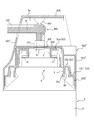
- the fixed platen 10A is mounted on the mounting cup 4.
- the tip of the thin tongue 14 is at the lower end of the protrusion 7.
- the fixed platen 10A is lowered to the height at which it comes into contact.
- the tip of the thin tongue 14 is in contact with the upper surface of the projection 7 and is positioned higher than the predetermined height. Will be. In other words, since it is possible to determine whether or not the directions of both are in accordance with the difference in height of the fixed platen 10A, the assembling work becomes easier.
- the fixed platen 10A when the fixed platen 10A is rotated, the fixed platen 10A moves downward when the orientations of the two are matched. Thereafter, when the fixed platen 10A is pushed in, the thin tongue piece 14 is bent outward as shown in FIG. 2, and the engaging claw 16a is engaged with the annular edge 5.
- the connecting portion 47 is fitted to the stem 6 of the aerosol container 2 with the nozzle 40A bent from the state shown in FIG. 9 to the state shown in FIGS.
- the nozzle 40A is disposed inside the upper peripheral wall 21c provided in the lower cover 20A as shown in FIG. 3, and the upper peripheral wall 21c has a front width as shown in FIG. 5 (a).
- (La 1 ) is narrower than the width of the rear width (Lb 1 ).
- the nozzle 40A has a front width (La 2 ) of the rear width (Lb) as shown in FIG. 2 ) It is narrower than the width of 2 ) and is configured to satisfy the relationship of Lb 2 > La 1 , so that it is possible to reliably prevent the problem of mounting the nozzle 40A in the reverse direction.
- the width (La 4 ) of the notch 31a shown in FIG. 7 (a) is wider in the upper cover 30A than the width (La 3 ) of the protrusion 21a of the lower cover 20A shown in FIG. 5 (a).
- the width (La 5 ) of the notch 32a shown in FIG. 8B is narrow (La 4 > La 3 > La 5 ).
- the peripheral wall 32 of the upper cover 30A cannot contact and be attached to the protruding portion 21a of the lower cover 20A.
- the second engagement piece 33 is smoothly bent radially inward during insertion. Therefore, it can be mounted with a smaller pushing force.
- the inner peripheral wall 35 can be along the upper peripheral wall 21c of the lower cover 20A, so that the inner peripheral wall 35 and the upper peripheral wall 21c function as a guide at the time of mounting.
- the overcap 50A is mounted on the upper cover 30A.
- the cap convex portion 53 of the overcap 50A engages with the cover convex portion 24b of the lower cover 20A, and the positioning rib 54 provided on the back surface of the overcap 50A is the top of the upper cover 30A. Since it enters the notch 31a provided in the wall 31, the overcap 50A is held at a predetermined position.
- the cover convex portion 24b and the cap convex portion 53 are provided one by one on the front and the rear of each side, the overcap 50A can be prevented from tilting forward, rear, and side. Is held more stable.
- the cover convex portion may be provided on the upper cover 30A.
- the lower cover 20A, the nozzle 40A, the upper cover 30A, and the overcap 50A are attached in advance to the fixed platen 10A in advance, and this is attached to the aerosol container 2. It is also possible. Moreover, after assembling from the fixed platen 10A to the upper cover 30A, this may be attached to the aerosol container 2, and then the overcap 50A may be attached.
- the overcap 50A is first removed. Thereafter, when the operation portion 34 of the upper cover 30A is pushed downward, the operation portion 34 comes into contact with the semicircular rib 41d of the nozzle 40A and pushes down the stem 6 connected to the nozzle 40A. Thereby, two types of contents are simultaneously ejected from the respective stems 6 and discharged from the outlet of the dispensing cylinder 42 through the passage R formed inside the nozzle 40A.
- the partition wall 43 provided in the nozzle 40A has only two upstream sides of the passage R (the stem 6 side of the passage R is referred to as the upstream side, and the outlet side of the extraction tube is referred to as the downstream side).
- the partition wall 43 may be extended to the vicinity of the outlet of the pouring tube 42 so that the substantially entire area of the passage R is defined as a dividing region (that is, inside the one pouring tube 42). Two passage portions are formed), and the partition region may be narrower than the present embodiment by shortening it toward the upstream side, or the partition wall 43 may be removed to omit the partition region.
- the cover member 60B generally has a function in which the lower cover 20A and the upper cover 30A are integrated, and includes a dome-shaped peripheral wall 61B cut out at the rear, and the cutout is provided with a hinge hd.
- An operation unit 62B is provided.
- An intermediate wall 63B that extends in the horizontal direction and contacts the upper surface of the upper step portion 12a provided on the fixed platen 10A is provided inside the peripheral wall 61B, and the stem 6 is inserted through the center of the intermediate wall 63B. An opening is provided. As shown in FIG.
- a plate-like convex portion 64B that fits into the slit-like concave portion 15 provided in the fixed plate 10A.
- two in the front and one in the rear are provided corresponding to the recess 15.
- the concave portion 15 and the convex portion 64B may be interchanged to provide a convex portion on the fixed platen 10A and a concave portion on the cover member 60B.
- the peripheral wall 61B is provided with a pair of first engaging pieces 65B extending downward, and the first engaging pieces 65B are provided with claw portions 65B 1 facing outward in the radial direction.
- both sides of the first engagement piece 65B are separated from the peripheral wall 61B by slits 66B extending in the vertical direction and bent inward by being pushed in from the outside.
- the cover member 60B can be removed.
- a pair of inner ribs 67B are provided on both sides of the first engagement piece 65B.
- the pair of inner ribs 67B are provided at positions sandwiched between a pair of outer ribs 18b (see FIG. 4A) provided on the fixed platen 10A.
- the nozzle 40B is generally obtained by omitting the opening / closing function of the nozzle 40A, and includes two connecting portions 41B connected to the stem 6 and one outlet serving as an outlet for the contents.
- the cylinder 42B is integrally connected, and a content passage R is provided inside thereof.
- the passage R is provided with a partition wall 43B.
- a semicircular rib 44B is provided on the upper portion of the nozzle 40A so that the operation portion 62B is pressed when the contents are discharged.
- the overcap 50B is formed by integrally connecting an outer peripheral wall 52B having an outer surface shape gradually decreasing inward in the radial direction from above to the outer edge of the disk-shaped top wall 51B. Is housed inside. This makes it difficult for dust and the like to adhere to the dispensing cylinder 42B.
- the fixed platen 10B is roughly the same shape as the fixed platen 10A. However, as shown in FIG. 16, an engaging piece 11B formed to bend inward is provided on the outer peripheral surface of the intermediate step portion 12b. Further, the engagement piece 11B is provided with a pressure receiving portion 12B which extend toward the distal end upwardly provided with a claw portion 11B 1 that faces radially outward.
- the cover member 60C has a function of integrating the lower cover 20A and the upper cover 30A, and includes an angular dome-shaped peripheral wall 61C having a notch on the rear side.
- An operation portion 62C is provided in the notch via a hinge he.
- An inner wall 63C that covers the upper stage 12a of the stationary platen 10B is provided inside the peripheral wall 61C, and an opening through which the stem 6 is inserted is provided at the center of the inner wall 63C.
- a pressing portion 64C via a hinge hf below the pressing portion 64C, the claw portion 11B 1 of the engagement piece 11B is engaged
- An engagement hole 65C is provided.
- the nozzle 40C integrally connects the two connecting portions 41C connected to the stem 6 and the two extraction cylinders 42C connected to the connecting portions, respectively, and includes a passage R for the contents independently of each other (inside thereof) ( There are a total of two passages R).
- a claw portion 43C that engages with the opening edge of the inner wall 63C is provided at the lower end of the connecting portion 41C, and the nozzle 40C is retained from the cover member 60C.
- a rib 66C having a circular arc at the tip is provided on the back surface of the operation portion 62C described above, and when the operation portion 62C is pressed, the rib 66C hits the upper surface of the nozzle 40C, and the contents from each stem 6 Are simultaneously discharged.
- the fixed platen 10B ′ is roughly the same shape as the fixed platen 10B, but the peripheral wall of the lower step portion 12c ′ is closer to the radially inner side than the outer peripheral surface of the aerosol container 2 as shown in FIG. As shown in FIG. 18, an outward claw portion 11C is provided.
- the cover member 60C ′ is roughly the same shape as the cover member 60C.
- the peripheral wall 61C ′ accommodates the lower step portion 12c ′ of the stationary platen 10B ′ inside and the outer peripheral surface of the aerosol container 2.
- the outer shape has substantially the same diameter.
- the entire fixed platen 10B ' is covered with the cover member 60C', so that it is not necessary to apply a special decorative effect to the fixed platen 10B '.
- a swing piece 68C having an engagement hole 67C that engages with the claw portion 11C is provided on the side surface of the peripheral wall 61C '.
- the swinging piece 68C is connected to the peripheral wall 61C ′ at the front and rear by a connecting piece 69C indicated by a broken line in the drawing, and the upper area of the swinging piece 68C positioned above the connecting piece 69C is set inward.
- the swinging piece 68C swings around the connecting piece 69C, and the engagement hole 67C is displaced outwardly to release the engagement with the claw portion 11C.
- the fixing plate according to the present invention can be attached with various cover members without changing the main part, the development efficiency is increased and the cost can be suppressed.
Landscapes
- Chemical & Material Sciences (AREA)
- Dispersion Chemistry (AREA)
- Engineering & Computer Science (AREA)
- Mechanical Engineering (AREA)
- Containers And Packaging Bodies Having A Special Means To Remove Contents (AREA)
- Nozzles (AREA)
- Package Specialized In Special Use (AREA)
Priority Applications (6)
| Application Number | Priority Date | Filing Date | Title |
|---|---|---|---|
| ES13880991.8T ES2678195T3 (es) | 2013-04-03 | 2013-11-13 | Placa de fijación para un envase de aerosol |
| KR1020157029426A KR101820757B1 (ko) | 2013-04-03 | 2013-11-13 | 에어로졸 용기용 고정반 |
| EP13880991.8A EP2982615B1 (en) | 2013-04-03 | 2013-11-13 | Fixing plate for an aerosol container |
| CN201380075204.5A CN105636880B (zh) | 2013-04-03 | 2013-11-13 | 喷雾容器用固定盘 |
| BR112015023478-0A BR112015023478B1 (pt) | 2013-04-03 | 2013-11-13 | placa de fixação para um recipiente aerossol |
| US14/716,497 US9737902B2 (en) | 2013-04-03 | 2015-05-19 | Aerosol container fixing plate |
Applications Claiming Priority (2)
| Application Number | Priority Date | Filing Date | Title |
|---|---|---|---|
| JP2013-077931 | 2013-04-03 | ||
| JP2013077931A JP5901564B2 (ja) | 2013-04-03 | 2013-04-03 | エアゾール容器用固定盤 |
Related Child Applications (1)
| Application Number | Title | Priority Date | Filing Date |
|---|---|---|---|
| US14/716,497 Continuation US9737902B2 (en) | 2013-04-03 | 2015-05-19 | Aerosol container fixing plate |
Publications (1)
| Publication Number | Publication Date |
|---|---|
| WO2014162629A1 true WO2014162629A1 (ja) | 2014-10-09 |
Family
ID=51657949
Family Applications (1)
| Application Number | Title | Priority Date | Filing Date |
|---|---|---|---|
| PCT/JP2013/080702 Ceased WO2014162629A1 (ja) | 2013-04-03 | 2013-11-13 | エアゾール容器用固定盤 |
Country Status (10)
| Country | Link |
|---|---|
| US (1) | US9737902B2 (enExample) |
| EP (1) | EP2982615B1 (enExample) |
| JP (1) | JP5901564B2 (enExample) |
| KR (1) | KR101820757B1 (enExample) |
| CN (1) | CN105636880B (enExample) |
| BR (1) | BR112015023478B1 (enExample) |
| DE (1) | DE202013012140U1 (enExample) |
| ES (1) | ES2678195T3 (enExample) |
| PT (1) | PT2982615T (enExample) |
| WO (1) | WO2014162629A1 (enExample) |
Families Citing this family (8)
| Publication number | Priority date | Publication date | Assignee | Title |
|---|---|---|---|---|
| JP5901565B2 (ja) * | 2013-04-03 | 2016-04-13 | 東洋エアゾール工業株式会社 | エアゾール容器用吐出具 |
| JP5901564B2 (ja) * | 2013-04-03 | 2016-04-13 | 東洋エアゾール工業株式会社 | エアゾール容器用固定盤 |
| BR112015029341B1 (pt) * | 2013-05-31 | 2021-07-06 | Toyo Aerosol Industry Co., Ltd | cobertura saliente para recipiente aerossol |
| WO2016208488A1 (ja) * | 2015-06-23 | 2016-12-29 | 株式会社三谷バルブ | マウンティングカップ外装品用アダプタ,エアゾール噴射機構およびエアゾール式製品 |
| KR102050344B1 (ko) * | 2016-01-18 | 2019-11-29 | 도요 에어로졸 고교 가부시키가이샤 | 에어로졸 용기용 고정반 |
| JP6932626B2 (ja) * | 2017-09-15 | 2021-09-08 | 株式会社マンダム | ノズルユニット、ならびにそれを備える二液吐出器 |
| FR3092091B1 (fr) | 2019-01-25 | 2021-08-13 | Lindal France | Diffuseur pour récipient sous pression |
| JP6755632B2 (ja) * | 2019-04-04 | 2020-09-16 | 株式会社吉野工業所 | 二連式エアゾール用アクチュエータ |
Citations (6)
| Publication number | Priority date | Publication date | Assignee | Title |
|---|---|---|---|---|
| JPS6041340U (ja) * | 1983-08-31 | 1985-03-23 | 凸版印刷株式会社 | ディスペンサー用オーバーキャップ |
| JP2002193363A (ja) * | 2000-12-22 | 2002-07-10 | Maruichi Valve Co Ltd | 複数液型のエアゾールバルブ装置 |
| JP2005041510A (ja) | 2003-07-25 | 2005-02-17 | Mandom Corp | 二連エアゾール式液体噴出容器 |
| JP2009023684A (ja) * | 2007-07-19 | 2009-02-05 | Eiji Mori | 塗装スプレー缶 |
| JP2011213400A (ja) * | 2010-03-31 | 2011-10-27 | Yoshino Kogyosho Co Ltd | 二連式容器 |
| JP2012030886A (ja) * | 2010-08-03 | 2012-02-16 | Toyo Aerosol Ind Co Ltd | エアゾール容器用のアクチュエータ |
Family Cites Families (33)
| Publication number | Priority date | Publication date | Assignee | Title |
|---|---|---|---|---|
| US3156382A (en) * | 1962-08-17 | 1964-11-10 | W R Frank Packaging Engineers | Aerosol container adapter collar |
| US3180531A (en) * | 1964-02-18 | 1965-04-27 | Risdon Mfg Co | Overcap and actuating button for aerosol containers |
| US3333744A (en) * | 1965-10-22 | 1967-08-01 | Peter J Nilsen | Valve and nozzle construction for aerosol whipped cream dispenser |
| US3946912A (en) * | 1975-01-02 | 1976-03-30 | Emanuel Landsman | Actuator cap for aerosol dispenser |
| ZA764611B (en) * | 1976-07-30 | 1977-07-27 | A Almouli | Aerosol dispenser particularly useful as a pocket fire extinguisher |
| FR2603558B1 (fr) * | 1986-09-04 | 1988-11-18 | Oreal | Tete de distribution d'un produit pateux resultant du melange de deux composants stockes separement et ensemble de conditionnement dote d'une telle tete de distribution |
| DE19541594A1 (de) * | 1995-11-08 | 1997-05-15 | Pfeiffer Erich Gmbh & Co Kg | Austrag-Einheit für Medien |
| FR2748406B1 (fr) * | 1996-05-07 | 1998-08-28 | Valois | Dispositif de distribution a spray fixe |
| US6736288B1 (en) * | 2000-10-26 | 2004-05-18 | Ronald D. Green | Multi-valve delivery system |
| FR2815616B1 (fr) * | 2000-10-20 | 2003-01-24 | Oreal | Ensemble de distribution destine a la distribution extemporanee de deux produits |
| US6454139B1 (en) * | 2001-02-14 | 2002-09-24 | Precision Valve Corporation | Preassembled aerosol actuator assembly for in-line capping to an aerosol container |
| JP4051412B2 (ja) * | 2001-06-27 | 2008-02-27 | 株式会社カネボウ化粧品 | 混合注出装置 |
| US6691898B2 (en) * | 2002-02-27 | 2004-02-17 | Fomo Products, Inc. | Push button foam dispensing device |
| US7854350B2 (en) * | 2004-09-30 | 2010-12-21 | L'oreal | Distribution assembly intended for contemporaneous distribution of two products |
| US7748568B2 (en) * | 2005-08-25 | 2010-07-06 | L'oreal | Packaging and dispensing assembly |
| US7845518B2 (en) * | 2005-08-25 | 2010-12-07 | L'oreal | Product packaging and dispensing assembly |
| JP5046328B2 (ja) * | 2007-05-25 | 2012-10-10 | 株式会社三谷バルブ | 連結複数容器の内容物放出機構ならびに、この内容物放出機構を備えたエアゾール式製品およびポンプ式製品 |
| US9038858B2 (en) * | 2009-12-01 | 2015-05-26 | Toyo Aerosol Industry Co., Ltd. | Aerosol device for allocation of plurality of fluids |
| JP5413902B2 (ja) * | 2009-12-18 | 2014-02-12 | 株式会社三谷バルブ | 連結容器の内容物放出単一部材および、この内容物放出単一部材を備えたエアゾール式製品 |
| US8376186B2 (en) * | 2010-03-17 | 2013-02-19 | Yonyu Plastics Co., Ltd. | Fluid dispenser device |
| US20110226812A1 (en) * | 2010-03-17 | 2011-09-22 | Yonyu Plastics Co., Ltd. | Fluid dispenser device |
| US8978936B2 (en) * | 2010-07-12 | 2015-03-17 | Foamix Pharmaceuticals Ltd. | Apparatus and method for releasing a unit dose of content from a container |
| KR101410406B1 (ko) * | 2010-07-20 | 2014-06-20 | 도요 에어로졸 고교 가부시키가이샤 | 복수 액 분배용의 에어로졸 장치 |
| JP5674386B2 (ja) * | 2010-08-31 | 2015-02-25 | ホーユー株式会社 | 二液吐出器 |
| CN103097262B (zh) * | 2010-12-02 | 2014-12-17 | 东洋喷雾工业株式会社 | 多种液体分配用的喷雾器装置 |
| CN103328347B (zh) * | 2010-12-22 | 2015-05-27 | 株式会社大造 | 阀总成以及使用它的空气溶胶容器、空气溶胶制品及其制造方法 |
| JP5279970B1 (ja) * | 2011-08-30 | 2013-09-04 | 東洋エアゾール工業株式会社 | 残量低減部材 |
| USD731312S1 (en) * | 2013-02-20 | 2015-06-09 | Toyo Aerosol Industry Co., Ltd. | Fixture for aerosol spray container |
| JP5901565B2 (ja) * | 2013-04-03 | 2016-04-13 | 東洋エアゾール工業株式会社 | エアゾール容器用吐出具 |
| JP5901564B2 (ja) * | 2013-04-03 | 2016-04-13 | 東洋エアゾール工業株式会社 | エアゾール容器用固定盤 |
| JP6161958B2 (ja) * | 2013-05-31 | 2017-07-12 | 東洋エアゾール工業株式会社 | エアゾール容器用ノズルキャップ |
| BR112015029341B1 (pt) * | 2013-05-31 | 2021-07-06 | Toyo Aerosol Industry Co., Ltd | cobertura saliente para recipiente aerossol |
| JP6151575B2 (ja) * | 2013-05-31 | 2017-06-21 | 東洋エアゾール工業株式会社 | エアゾール容器用ノズル及びエアゾール容器用吐出具 |
-
2013
- 2013-04-03 JP JP2013077931A patent/JP5901564B2/ja active Active
- 2013-11-13 EP EP13880991.8A patent/EP2982615B1/en active Active
- 2013-11-13 PT PT138809918T patent/PT2982615T/pt unknown
- 2013-11-13 ES ES13880991.8T patent/ES2678195T3/es active Active
- 2013-11-13 WO PCT/JP2013/080702 patent/WO2014162629A1/ja not_active Ceased
- 2013-11-13 KR KR1020157029426A patent/KR101820757B1/ko active Active
- 2013-11-13 DE DE202013012140.8U patent/DE202013012140U1/de not_active Expired - Lifetime
- 2013-11-13 BR BR112015023478-0A patent/BR112015023478B1/pt active IP Right Grant
- 2013-11-13 CN CN201380075204.5A patent/CN105636880B/zh active Active
-
2015
- 2015-05-19 US US14/716,497 patent/US9737902B2/en active Active
Patent Citations (6)
| Publication number | Priority date | Publication date | Assignee | Title |
|---|---|---|---|---|
| JPS6041340U (ja) * | 1983-08-31 | 1985-03-23 | 凸版印刷株式会社 | ディスペンサー用オーバーキャップ |
| JP2002193363A (ja) * | 2000-12-22 | 2002-07-10 | Maruichi Valve Co Ltd | 複数液型のエアゾールバルブ装置 |
| JP2005041510A (ja) | 2003-07-25 | 2005-02-17 | Mandom Corp | 二連エアゾール式液体噴出容器 |
| JP2009023684A (ja) * | 2007-07-19 | 2009-02-05 | Eiji Mori | 塗装スプレー缶 |
| JP2011213400A (ja) * | 2010-03-31 | 2011-10-27 | Yoshino Kogyosho Co Ltd | 二連式容器 |
| JP2012030886A (ja) * | 2010-08-03 | 2012-02-16 | Toyo Aerosol Ind Co Ltd | エアゾール容器用のアクチュエータ |
Also Published As
| Publication number | Publication date |
|---|---|
| BR112015023478A2 (pt) | 2017-07-18 |
| PT2982615T (pt) | 2018-06-29 |
| US20150251202A1 (en) | 2015-09-10 |
| US9737902B2 (en) | 2017-08-22 |
| KR101820757B1 (ko) | 2018-01-22 |
| EP2982615B1 (en) | 2018-05-30 |
| CN105636880B (zh) | 2017-10-20 |
| BR112015023478B1 (pt) | 2021-05-11 |
| JP5901564B2 (ja) | 2016-04-13 |
| CN105636880A (zh) | 2016-06-01 |
| KR20150130538A (ko) | 2015-11-23 |
| EP2982615A4 (en) | 2017-02-08 |
| ES2678195T3 (es) | 2018-08-09 |
| JP2014201329A (ja) | 2014-10-27 |
| EP2982615A1 (en) | 2016-02-10 |
| DE202013012140U1 (de) | 2015-05-06 |
Similar Documents
| Publication | Publication Date | Title |
|---|---|---|
| JP5901564B2 (ja) | エアゾール容器用固定盤 | |
| JP5901565B2 (ja) | エアゾール容器用吐出具 | |
| JP2017030801A (ja) | 吐出具 | |
| JP6126917B2 (ja) | 多連式容器 | |
| JP6180885B2 (ja) | エアゾール容器用肩カバー | |
| JP6599177B2 (ja) | 吐出具 | |
| JP2012131511A (ja) | 噴射装置 | |
| JP2015127217A (ja) | エアゾール容器用肩カバー | |
| KR101827780B1 (ko) | 에어로졸 용기용 어깨 커버 | |
| JP6362849B2 (ja) | エアゾール容器用アクチュエータ | |
| JP6258118B2 (ja) | エアゾール容器用吐出具 | |
| JP6051106B2 (ja) | エアゾール容器用肩カバー | |
| JP6584364B2 (ja) | 吐出具 | |
| JP2018122895A (ja) | エアゾール容器用吐出具 | |
| JP2605778Y2 (ja) | エアゾ−ル容器用ハウジング | |
| JP7146349B2 (ja) | エアゾール容器用吐出具 | |
| JP6866013B2 (ja) | エアゾール容器用吐出具 | |
| JP4684091B2 (ja) | エアゾール容器のキャップ | |
| JP4731318B2 (ja) | エアゾール容器用オーバーキャップ | |
| JP6656951B2 (ja) | 吐出容器 | |
| JP2019182538A (ja) | 吐出部材 | |
| JP2016033042A (ja) | エアゾール容器用肩カバー | |
| JP2002264956A (ja) | エアゾール容器のマウンティングカップカバー |
Legal Events
| Date | Code | Title | Description |
|---|---|---|---|
| 121 | Ep: the epo has been informed by wipo that ep was designated in this application |
Ref document number: 13880991 Country of ref document: EP Kind code of ref document: A1 |
|
| WWE | Wipo information: entry into national phase |
Ref document number: 2013880991 Country of ref document: EP |
|
| NENP | Non-entry into the national phase |
Ref country code: DE |
|
| ENP | Entry into the national phase |
Ref document number: 20157029426 Country of ref document: KR Kind code of ref document: A |
|
| REG | Reference to national code |
Ref country code: BR Ref legal event code: B01A Ref document number: 112015023478 Country of ref document: BR |
|
| ENP | Entry into the national phase |
Ref document number: 112015023478 Country of ref document: BR Kind code of ref document: A2 Effective date: 20150915 |