WO2014162628A1 - 回転陽極型x線管ユニット及び回転陽極型x線管装置 - Google Patents
回転陽極型x線管ユニット及び回転陽極型x線管装置 Download PDFInfo
- Publication number
- WO2014162628A1 WO2014162628A1 PCT/JP2013/079764 JP2013079764W WO2014162628A1 WO 2014162628 A1 WO2014162628 A1 WO 2014162628A1 JP 2013079764 W JP2013079764 W JP 2013079764W WO 2014162628 A1 WO2014162628 A1 WO 2014162628A1
- Authority
- WO
- WIPO (PCT)
- Prior art keywords
- ray tube
- ray
- housing
- anode
- shield
- Prior art date
- Legal status (The legal status is an assumption and is not a legal conclusion. Google has not performed a legal analysis and makes no representation as to the accuracy of the status listed.)
- Ceased
Links
Images


Classifications
-
- H—ELECTRICITY
- H05—ELECTRIC TECHNIQUES NOT OTHERWISE PROVIDED FOR
- H05G—X-RAY TECHNIQUE
- H05G1/00—X-ray apparatus involving X-ray tubes; Circuits therefor
- H05G1/02—Constructional details
-
- H—ELECTRICITY
- H05—ELECTRIC TECHNIQUES NOT OTHERWISE PROVIDED FOR
- H05G—X-RAY TECHNIQUE
- H05G1/00—X-ray apparatus involving X-ray tubes; Circuits therefor
- H05G1/02—Constructional details
- H05G1/025—Means for cooling the X-ray tube or the generator
-
- H—ELECTRICITY
- H05—ELECTRIC TECHNIQUES NOT OTHERWISE PROVIDED FOR
- H05G—X-RAY TECHNIQUE
- H05G1/00—X-ray apparatus involving X-ray tubes; Circuits therefor
- H05G1/02—Constructional details
- H05G1/04—Mounting the X-ray tube within a closed housing
Definitions
- Embodiments of the present invention relate to a rotating anode X-ray tube unit and a rotating anode X-ray tube apparatus.
- an X-ray apparatus using a rotating anode X-ray tube apparatus as an X-ray source is used.
- Examples of X-ray imaging include X-ray imaging and CT imaging.
- the rotating anode X-ray tube apparatus comprises a housing, a rotating anode X-ray tube housed in the housing and emitting X-rays, and an insulating oil filled in a space between the housing and the rotating anode X-ray tube And.
- the housing is formed of a brittle material such as aluminum casting.
- a lead plate is attached to the inner surface of the housing for shielding X-rays.
- an X-ray transmission window that transmits X-rays is provided on the outer wall of the housing.
- the rotating anode X-ray tube includes an anode target, a cathode, and a vacuum envelope that accommodates the anode target and the cathode and the pressure inside is reduced.
- the anode target is capable of high speed rotation (for example, 10000 RPM).
- the anode target is capable of high speed rotation (for example, 10000 RPM), and has a target layer (an umbrella portion) formed of a tungsten alloy.
- the cathode is located eccentrically from the rotation axis of the anode target and faces the target layer.
- a high voltage is applied between the cathode and the anode target.
- the cathode emits electrons
- the electrons are accelerated and focused to collide with the target layer.
- the target layer emits X-rays and is emitted from the X-ray transmission window to the outside of the housing.
- JP 2000-48745 A Unexamined-Japanese-Patent No. 2010-211939 JP, 2010-244940, A Unexamined-Japanese-Patent No. 2010-244941 JP, 2010-257900, A JP, 2010-257902, A
- the above-mentioned rotating anode X-ray tube apparatus has the following problems.
- the rotating anode X-ray tube is generally a rotating anode X-ray tube since the rate of occurrence of defects such as discharge occurrence increases (discharge failure) increases with long-term use.
- the life is short compared to the life of other parts of the X-ray apparatus. For this reason, replacement of the rotary anode X-ray tube apparatus is inevitable every several years, and transportation in units of rotary anode X-ray tube apparatuses is required after each replacement.
- the rotating anode X-ray tube unit is not a rotating anode X-ray tube unit, but the X-ray transmission window is in a state where the rotating anode X-ray tube is housed with insulating oil in a housing having an X-ray shielding function. This is because it is necessary to carry out a test for confirming that there is no X-ray leakage from others, using an expensive, large-scale, special dedicated facility. Even if it is possible to replace a rotating anode X-ray tube that has become defective at the transport destination with a new rotating anode X-ray tube, it is difficult to carry out the above test.
- a blackening film is generally deposited on the outer surface of the anode target or on the surface of the anode target opposite to the target layer. Since the anode target is heated by the collision of electrons during use of the rotating anode X-ray tube, the heat generated in the anode target is released from the blackened film to the inner surface of the opposing vacuum envelope by heat radiation. Be done. Part of the heat generated in the anode target is transferred to the rotor connected to the anode target, and released from the blackened film deposited on the outer surface of the rotor to the inner surface of the opposing vacuum envelope by heat radiation. The released heat heat heats the nearby insulating oil.
- a lead plate which is an X-ray shielding material, is attached to the inner wall of the housing over a wide range. Although the inner wall of the housing and the lead plate are partially bonded, in most parts, a very narrow gap in which the insulating oil does not easily flow is formed, and the insulating oil remains in the gap. For this reason, the heat transferred to the lead plate is less likely to be transferred to the housing, so the heat dissipation is reduced, and the insulating oil near the anode target and near the rotor is easily overheated.
- the insulating oil When the insulating oil is overheated, it carbonizes, and the carbonized product is deposited on the surface of the vacuum envelope. For this reason, when the vacuum envelope is glass, heat rays are absorbed by the deposited film (product), which causes overheating of the vacuum envelope.
- the vacuum envelope When the vacuum envelope is overheated, the gas adsorbed on the inner wall of the vacuum envelope is released into the vacuum space, and the discharge frequency of the rotating anode X-ray tube is increased.
- the embodiment of the present invention has been made in view of the above points, and an object thereof is a rotating anode X-ray tube unit capable of independently performing an X-ray leakage test and improving the heat dissipation of an anode target. And a rotating anode X-ray tube apparatus provided with the rotating anode X-ray tube unit. In the rotary anode X-ray tube apparatus, the manufacturing cost of the housing can be further reduced.
- a rotating anode X-ray tube unit comprises A rotating anode X-ray tube having a cathode emitting electrons, a rotatable anode target emitting X-rays, and a vacuum envelope containing the cathode and the anode target; A flow path forming body having a shell surrounding the vacuum envelope in a direction perpendicular to the axis of the anode target, and forming a flow path for a cooling medium to flow between the shell and the vacuum envelope; And X-ray shielding means for preventing leakage of the X-rays.
- a rotary anode X-ray tube apparatus A rotating anode X-ray tube unit, A housing that accommodates the rotating anode X-ray tube unit and forms a space through which a cooling medium flows with the rotating anode X-ray tube unit;
- the rotating anode X-ray tube unit is A rotating anode X-ray tube having a cathode emitting electrons, a rotatable anode target emitting X-rays, and a vacuum envelope containing the cathode and the anode target;
- a flow path forming member having a shell surrounding the vacuum envelope in a direction perpendicular to the axis of the anode target, and forming a flow path for the cooling medium to flow between the shell and the vacuum envelope;
- X-ray shielding means for preventing leakage of the X-rays.
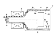
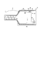
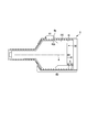
- FIG. 1 is a cross-sectional view showing a rotary anode X-ray tube apparatus according to the first embodiment.
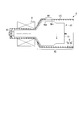
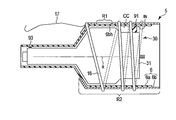
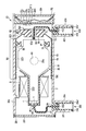
- FIG. 2 is a cross-sectional view showing a rotary anode X-ray tube unit according to the first embodiment.
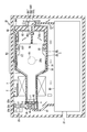
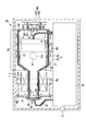
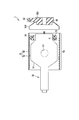
- FIG. 3 is a cross-sectional view showing a rotary anode X-ray tube according to the first embodiment.
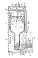
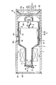
- FIG. 4 is a cross-sectional view showing a rotary anode X-ray tube apparatus according to a second embodiment.
- FIG. 5 is a cross-sectional view showing a rotary anode X-ray tube apparatus according to a third embodiment.
- FIG. 1 is a cross-sectional view showing a rotary anode X-ray tube apparatus according to the first embodiment.
- FIG. 2 is a cross-sectional view showing a rotary anode X-ray tube unit according to the first embodiment.
- FIG. 3 is a cross-sectional view showing a rotary anode X-
- FIG. 6 is a cross-sectional view showing a modification of the rotary anode X-ray tube unit of the rotary anode X-ray tube device according to the first to third embodiments.
- FIG. 7 is a cross-sectional view showing another modification of the rotary anode X-ray tube unit of the rotary anode X-ray tube device according to the first to third embodiments.
- FIG. 8 is a cross-sectional view showing another modification of the rotary anode X-ray tube unit of the rotary anode X-ray tube apparatus according to the first and second embodiments.
- FIG. 9 is a cross-sectional view showing a rotary anode X-ray tube apparatus according to a fourth embodiment.
- FIG. 10 is a cross-sectional view showing a rotary anode X-ray tube unit according to the fourth embodiment.
- FIG. 11 is a cross-sectional view showing another modification of the rotary anode X-ray tube unit of the rotary anode X-ray tube apparatus according to the fourth embodiment.
- FIG. 12 is a cross-sectional view showing another modification of the rotary anode X-ray tube unit of the rotary anode X-ray tube apparatus according to the fourth embodiment.
- FIG. 13 is a cross-sectional view showing another modification of the rotary anode X-ray tube unit of the rotary anode X-ray tube apparatus according to the fourth embodiment.
- FIG. 11 is a cross-sectional view showing another modification of the rotary anode X-ray tube unit of the rotary anode X-ray tube apparatus according to the fourth embodiment.
- FIG. 12 is a cross-sectional view showing another modification of the rotary anode X-ray tube unit of the
- FIG. 14 is a cross-sectional view showing another modification of the rotary anode X-ray tube unit of the rotary anode X-ray tube apparatus according to the fourth embodiment.
- FIG. 15 is a cross-sectional view showing another modification of the rotary anode X-ray tube unit of the rotary anode X-ray tube apparatus according to the fourth embodiment.
- FIG. 16 is a cross-sectional view showing a rotating anode X-ray tube apparatus according to a fifth embodiment.
- FIG. 17 is a cross-sectional view showing a rotary anode X-ray tube apparatus according to a sixth embodiment.
- FIG. 18 is a cross-sectional view showing a rotary anode X-ray tube unit according to the sixth embodiment.
- FIG. 19 is a schematic view showing a rotary anode X-ray tube apparatus according to a seventh embodiment, and is a view of the rotary anode X-ray tube apparatus viewed from the receptacle side.
- FIG. 20 is a cross-sectional view showing a rotating anode X-ray tube apparatus according to the seventh embodiment, taken along line XX-XX in FIG.
- FIG. 21 is a cross-sectional view showing a rotary anode X-ray tube apparatus according to an eighth embodiment.
- FIG. 22 is a schematic view showing a rotary anode X-ray tube apparatus according to the ninth embodiment, and is a view of the rotary anode X-ray tube apparatus viewed from the receptacle side.
- FIG. 20 is a cross-sectional view showing a rotating anode X-ray tube apparatus according to the seventh embodiment, taken along line XX-XX in FIG.
- FIG. 21 is a cross-sectional view showing a
- FIG. 23 is a cross-sectional view of the rotary anode X-ray tube apparatus according to the ninth embodiment, taken along line XXIII-XXIII of FIG.
- FIG. 24 is a cross-sectional view taken along line XXIV-XXIV of FIG. 22, showing the rotary anode X-ray tube apparatus according to the ninth embodiment.
- FIG. 25 is a cross-sectional view taken along line XXV-XXV of FIG. 22 and showing a rotary anode X-ray tube apparatus according to the ninth embodiment.
- FIG. 26 is a cross-sectional view showing a rotary anode X-ray tube apparatus according to a tenth embodiment.
- FIG. 27 is a cross-sectional view showing a rotating anode X-ray tube apparatus as a comparative example of the X-ray tube apparatus according to the first to tenth embodiments.
- FIG. 28 is a cross-sectional view showing a rotary anode X-ray tube apparatus according to an eleventh embodiment.
- FIG. 29 is a cross-sectional view showing another modification of the rotary anode X-ray tube unit of the rotary anode X-ray tube apparatus according to the eleventh embodiment.
- FIG. 30 is a cross-sectional view showing another modification of the rotary anode X-ray tube unit of the rotary anode X-ray tube apparatus according to the eleventh embodiment.
- FIG. 28 is a cross-sectional view showing a rotating anode X-ray tube apparatus as a comparative example of the X-ray tube apparatus according to the first to tenth embodiments.
- FIG. 28 is a cross-sectional view showing a rotary anode
- FIG. 31 is a cross-sectional view showing another modification of the rotary anode X-ray tube unit of the rotary anode X-ray tube apparatus according to the eleventh embodiment.
- FIG. 32 is a cross-sectional view showing another modification of the rotary anode X-ray tube unit of the rotary anode X-ray tube apparatus according to the eleventh embodiment.
- FIG. 33 is a cross-sectional view showing another modification of the rotary anode X-ray tube unit of the rotary anode X-ray tube apparatus according to the eleventh embodiment.
- FIG. 34 is a cross-sectional view showing a rotary anode X-ray tube apparatus according to a twelfth embodiment.
- FIG. 35 is a cross-sectional view showing a rotary anode X-ray tube unit according to the twelfth embodiment.
- FIG. 36 is a cross-sectional view showing a rotary anode X-ray tube apparatus according to a thirteenth embodiment.
- FIG. 37 is a cross-sectional view showing a rotary anode X-ray tube apparatus according to a fourteenth embodiment.
- FIG. 38 is a cross-sectional view showing a rotary anode X-ray tube apparatus according to a fifteenth embodiment.
- FIG. 39 is a schematic view showing a rotary anode X-ray tube apparatus according to a sixteenth embodiment, and is a view of the rotary anode X-ray tube apparatus as viewed from the receptacle side.
- FIG. 40 is a cross-sectional view showing a rotating anode X-ray tube apparatus according to the sixteenth embodiment, taken along line XL-XL in FIG.
- FIG. 41 is a cross-sectional view taken along line XLI-XLI in FIG. 39, showing the rotary anode X-ray tube apparatus according to the sixteenth embodiment.
- FIG. 42 is a cross-sectional view taken along line XLII-XLII of FIG. 39, showing a rotary anode X-ray tube apparatus according to the sixteenth embodiment.
- FIG. 43 is a cross-sectional view showing a rotary anode X-ray tube apparatus according to a seventeenth embodiment.
- FIG. 40 is a cross-sectional view showing a rotating anode X-ray tube apparatus according to the sixteenth embodiment, taken along line XL-XL in FIG.
- FIG. 41 is a cross-sectional view taken along line XLI-XLI in FIG. 39, showing the rotary anode
- FIG. 44 is a cross-sectional view showing a rotary anode X-ray tube apparatus according to an eighteenth embodiment.
- FIG. 45 is a cross-sectional view showing a rotary anode X-ray tube apparatus according to a nineteenth embodiment.
- FIG. 46 is a cross-sectional view showing a rotary anode X-ray tube apparatus according to a twentieth embodiment.
- FIG. 47 is a cross-sectional view showing a rotary anode X-ray tube apparatus according to a twenty-first embodiment.
- FIG. 48 is a cross-sectional view showing a rotary anode X-ray tube apparatus according to a twenty-second embodiment.
- FIG. 49 is a cross-sectional view showing a rotary anode X-ray tube unit according to the twenty-second embodiment.
- FIG. 50 is a cross-sectional view showing a rotary anode X-ray tube apparatus according to a twenty-third embodiment.
- FIG. 51 is a cross-sectional view showing a rotary anode X-ray tube unit according to the twenty-third embodiment.
- FIG. 52 is a cross-sectional view showing a rotary anode X-ray tube apparatus according to a twenty-fourth embodiment.
- FIG. 53 is a cross-sectional view showing a rotary anode X-ray tube apparatus according to a twenty-fifth embodiment.
- FIG. 54 is an exploded cross-sectional view of a rotary anode X-ray tube unit according to the twenty-fifth embodiment.
- FIG. 55 is a cross-sectional view showing a rotary anode X-ray tube apparatus according to a twenty-sixth embodiment.
- FIG. 56 is a cross-sectional view showing a rotary anode X-ray tube apparatus according to a twenty-seventh embodiment.
- FIG. 57 is a cross-sectional view showing a rotary anode X-ray tube unit according to the twenty-seventh embodiment.
- FIG. 58 is a cross-sectional view showing a modification of the rotary anode X-ray tube unit of the rotary anode X-ray tube apparatus according to the twenty-seventh embodiment.
- FIG. 1 is a cross-sectional view showing an X-ray tube apparatus according to the present embodiment.
- FIG. 2 is a cross-sectional view showing a rotary anode X-ray tube unit according to the present embodiment.
- FIG. 3 is a cross-sectional view showing a rotary anode X-ray tube according to the present embodiment.
- the X-ray tube apparatus roughly fills the space between the housing 20, the rotary anode type X-ray tube 30 housed in the housing 20, and the X-ray tube 30 and the housing 20.
- the cooling liquid 7 as the cooling medium, the shield structure 6, the stator coil 9 as the rotation driving part, the circulating part 23, the high voltage cables 61 and 71, and the receptacles 300 and 400 are provided.
- the housing 20 has a cylindrical housing body 20e and lids 20f, 20g and 20h.
- the housing main body 20e is formed of a resin material.
- the lids 20f, 20g and 20h are made of metal or resin material. Even when a resin material is used, a portion such as a portion requiring strength, such as a screw portion, a portion which is difficult to be molded by injection molding of a resin, or a shielding layer for preventing leakage of electromagnetic noise to the outside of the housing 20 described later Metal may be used together.
- the resin material is a thermosetting epoxy resin, unsaturated polyester resin, phenol resin, diallyl phthalate resin, thermoplastic epoxy resin, nylon resin, aromatic nylon resin, polybutylene terephthalate resin, polyethylene terephthalate resin, polycarbonate resin, polyphenylene sulfide And at least one of a resin, a polyphenylene ether resin, a liquid crystal polymer and a methylpentene polymer.
- a frame-shaped stepped portion is formed in the opening of the housing body 20e on the side where the high voltage supply terminal 44 described later is located.
- a frame-shaped groove is formed on the inner circumferential surface of the stepped portion. In the direction along the tube axis of the X-ray tube device, the peripheral portion of the lid 20f is in contact with the stepped portion of the housing body 20e.
- a C-shaped snap ring 20i is fitted in the groove of the housing body 20e.
- the C-shaped retaining ring 20i regulates the position of the lid 20f relative to the housing body 20e in the direction along the tube axis.
- the position of the lid 20 f is fixed in order to prevent the lid 20 f from rattling.
- the gap between the housing body 20e and the lid 20f is sealed in a fluid-tight manner by an O-ring.
- the O-ring has a function of preventing the coolant 7 from leaking to the outside of the housing 20.
- the O-ring is made of resin or rubber. From the above, the opening of the housing body 20e on the side where the high voltage supply terminal 44 is located is closed in a fluid-tight manner by the lid 20f, the C-shaped snap ring 20i and the O-ring.
- a frame-shaped stepped portion is formed at the opening of the housing body 20e on the side where the high voltage supply terminal 54 described later is located.
- a frame-shaped groove is formed on the inner circumferential surface of the stepped portion.
- the lid 20g is located inside the housing body 20e. In the direction along the tube axis, the peripheral edge portion of the lid portion 20g sandwiches the X-ray shielding portion 510 described later together with the step portion of the housing main body 20e.
- the lid 20 h faces the lid 20 g.
- the lid portion 20 h has an annular portion, and the annular portion is formed so as to protrude toward the lid portion 20 g.
- the gap between the inner peripheral surface of the housing body 20e and the lid 20g and the lid 20h is sealed in a fluid-tight manner by a frame-shaped O-ring.
- the O-ring is formed at the peripheral portion of the rubber bellows 21 and has a function of preventing the coolant 7 from leaking to the outside of the housing 20.
- a C-shaped snap ring 20j is fitted in the groove of the housing body 20e.
- the C-shaped retaining ring 20 j holds a state in which the lid 20 h applies stress to the O-ring. From the above, the opening of the housing body 20e on the side where the high voltage supply terminal 54 is located is closed in a fluid-tight manner by the lid 20g, the lid 20h, the C-shaped snap ring 20j and the rubber bellows 21.
- the housing 20 has an X-ray radiation window 20 w facing the X-ray transmission region R1.
- the X-ray radiation window 20 w transmits X-rays and radiates it to the outside of the housing 20.
- the X-ray radiation window 20w is formed by a part of the housing body 20e.
- the lead plate is not attached to the inner surface of the housing 20.
- the lid 20 g has an opening 20 k through which the coolant 7 enters and exits.
- the lid 20 h is formed with an air vent 20 m through which air as an atmosphere enters and exits.
- the rubber bellows 21 divides the region surrounded by the lid 20g and the lid 20h into a first space connected to the opening 20k and a second space connected to the vent 20m. The pressure adjustment of the coolant 7 is performed by the rubber bellows 21.
- the X-ray tube 30 is provided with a vacuum envelope 31.
- the vacuum envelope 31 has a vacuum vessel 32.
- the vacuum vessel 32 is made of, for example, glass or metal such as copper, stainless steel and aluminum. In this embodiment, the vacuum vessel 32 is formed of glass.
- the vacuum container 32 has an opening facing the X-ray transmission region R1. The opening of the vacuum vessel 32 is airtightly closed by an X-ray transmission window formed of beryllium as a material transmitting X-rays.
- a part of the vacuum envelope 31 is formed of a high voltage insulating member 50. In the present embodiment, the high voltage insulating member 50 is formed of glass.
- the X-ray tube 30 has an anode target 35 and a cathode 36.
- the anode target 35 is provided in the vacuum envelope 31.
- the anode target 35 is formed in a disk shape.
- the anode target 35 has an umbrella-like target layer 35 a provided on a part of the outer surface of the anode target.
- the target layer 35 a emits X-rays by collision of the electrons emitted from the cathode 36.
- the anode target 35 is formed of a metal such as molybdenum.
- the outer surface of the anode target 35 and the surface of the anode target 35 opposite to the target layer 35a are blackened.
- the target layer 35 a is formed of a metal such as molybdenum, a molybdenum alloy, or a tungsten alloy.
- the anode target 35 is rotatable around the tube axis. Therefore, the axis a of the anode target 35 is parallel to the tube axis.
- the cathode 36 is provided in the vacuum envelope 31.
- the cathode 36 emits electrons that irradiate the anode target 35.
- a relatively negative voltage is applied to the cathode 36.
- the low expansion alloy KOV member 55 covers the high voltage supply terminal 54 in the vacuum envelope 31.
- the high voltage supply terminal 54 and the high voltage insulating member 50 are sealed with glass, and the KOV member 55 is fixed to the high voltage insulating member 50 using a friction fit.
- the cathode support member 37 is attached to the KOV member 55.
- the cathode 36 is attached to the cathode support member 37.
- the high voltage supply terminal 54 is connected to the cathode 36 through the inside of the cathode support member 37.
- the high voltage supply terminal 54 applies a relatively negative voltage to the cathode 36 and supplies a filament current to a filament (electron emission source) (not shown) of the cathode 36.
- the X-ray tube 30 includes a fixed shaft 1, a rotating body 2, a bearing 3 and a rotor 10.
- the fixed shaft 1 is formed in a cylindrical shape.
- a protrusion is formed on a part of the outer periphery of the fixed shaft 1, and the protrusion is airtightly attached to the vacuum envelope 31.
- a high voltage supply terminal 44 is electrically connected to the fixed shaft 1.
- the fixed shaft 1 rotatably supports the rotating body 2.
- the rotating body 2 is formed in a cylindrical shape and provided coaxially with the fixed shaft 1.
- the rotor 10 is attached to the outer surface of the rotating body 2.
- An anode target 35 is attached to the rotating body 2.
- the bearing 3 is formed between the fixed shaft 1 and the rotating body 2.
- the rotating body 2 is rotatably provided together with the anode target 35.
- the high voltage supply terminal 44 applies a relatively positive voltage to the anode target 35 via the fixed shaft 1, the bearing 3 and the rotating body 2.
- the fixing member 90 is provided inside the housing 20.
- the fixing member 90 fixes the position of the X-ray tube 30 relative to the housing 20.
- the fixing member 90 is formed of an electrically insulating material such as a resin.
- the fixing member 90 fixes the X-ray tube 30 (vacuum envelope 31) using a plurality of rubber members (electrical insulating members) 91.
- the fixing member 90 fixes the X-ray tube 30 together with the rubber member 91 at three and four points.
- the rubber member 91 is in contact with the vacuum envelope 31. For this reason, the fixing member 90 and the rubber member 91 fix the vacuum envelope 31 using a friction fit.
- the fixing member 90 itself is fixed to the housing 20.
- the fixing member 90 is fixed to the housing 20 using a plurality of rubber members (electrically insulating members) 92.
- the fixing member 90 is fixed to the housing 20 together with the rubber member 92 at three and four points.
- the rubber member 92 is in contact with the housing 20. For this reason, the fixing member 90 and the rubber member 92 are fixed to the housing 20 using a friction fit.
- Through holes 90 a and 90 b are formed in the fixing member 90.
- the through hole 90 a is used as a connection space between the high voltage supply terminal 54 and the high voltage cable 71.
- the through hole 90 b is used as a flow path of the coolant 7.
- an X-ray shielding unit 510 is provided on one end side of the housing 20 facing the target layer 35 a in the direction along the axis a.
- the X-ray blocking unit 510 is for blocking X-rays emitted from the target layer 35a.
- the X-ray shielding unit 510 is formed of a material including an X-ray opaque material.
- the X-ray shielding unit 510 includes a first shielding unit 511, a second shielding unit 512, and a third shielding unit 513.
- the first shielding portion 511 is attached to the lid 20 g on the side facing the target layer 35 a in the direction along the axis a.
- the first shielding portion 511 covers the entire lid 20 g.
- the first shielding portion 511 is formed to have an opening at a position facing the opening 20k, and maintains the flow of the coolant 7 through the opening 20k.
- the second shielding unit 512 is provided on the first shielding unit 511.
- the second shielding portion 512 shields X-rays which may be emitted to the outside of the housing 20 from the vicinity of the opening 20 k.
- the third shielding portion 513 is provided on the first shielding portion 511 and is formed in a tubular shape. Through holes are formed at a plurality of locations of the third shielding portion 513. The through hole is used as a passage through which the high voltage cable 71 passes and a flow passage of the coolant 7.
- the X-ray shielding unit 520 is attached to the fixing member 90 facing the X-ray shielding unit 510 in the direction along the axis a.
- the X-ray blocking portion 520 is formed to open at locations facing the through holes 90a and 90b.
- the X-ray shields 510 and 520 are grounded.
- the shield structure 6 surrounds the entire vacuum space of the vacuum envelope 31 in a direction perpendicular to the axis a.
- the shield structure 6 has an X-ray transmission region R1 transmitting X-rays, and an X-ray shielding region R2 shielding the X-rays and surrounding the X-ray transmission region R1.
- the shield structure 6 forms a flow path CC in which the cooling fluid 7 flows between the shield structure 6 and the vacuum envelope 31.
- the X-ray tube 30, the shield structure 6, the connecting member 40 and the stator coil 9 form a rotating anode type X-ray tube unit 5.
- the shield structure 6 has an insulating member 6a as a shell and an X-ray shield 6b.
- the flow path forming body formed by the insulating member 6 a forms a flow path through which the cooling fluid 7 flows with the vacuum envelope 31.
- the insulating member 6a is formed of an electrically insulating material.
- the insulating member 6a is provided in the vacuum envelope 31 with a gap in a direction perpendicular to the axis a. Further, the insulating member 6a surrounds the vacuum envelope 31 (the entire vacuum space of the vacuum envelope 31) in the direction perpendicular to the axis a.
- the insulating member 6a is formed in a tubular shape.
- the shape of the insulating member 6 a corresponds to the shape of the X-ray tube 30.
- the diameter of the insulating member 6a changes along the axis a.
- the insulating member 6 a electrically insulates the X-ray tube 30 from the housing 20 and the stator coil 9.
- the insulating member 6a is made of thermosetting epoxy resin, unsaturated polyester resin, phenol resin, diallyl phthalate resin, thermoplastic epoxy resin, nylon resin, aromatic nylon resin, polybutylene terephthalate resin, polyethylene terephthalate resin, polycarbonate resin, polyphenylene sulfide It is formed of a resin material containing at least one of resin, polyphenylene ether resin, liquid crystal polymer and methyl pentene polymer. Depending on conditions, the insulating member 6a functions as a protective body.
- the insulating member 6 a (shield structure 6) is fixed to the X-ray tube 30 via the connection member 40.
- the insulating member 6a and the connecting member 40 are mechanically and firmly connected.
- the connecting member 40 is made of brass or the like, and can be integrally molded with the insulating member 6a using an injection molding method.
- the insulating member 6 a is formed with a plurality of intakes IN for taking in the coolant 7.
- the insulating member 6 a forms an extraction port OUT for extracting the coolant 7 with the vacuum envelope 31.
- the X-ray shield 6b is fixed to the insulating member 6a.
- the X-ray shield 6b is provided in the X-ray shielding region R2 and shields X-rays.
- the X-ray shield 6b is grounded.
- the X-ray shield 6b includes a through hole 6bh overlapping with the X-ray transmission region R1.
- the through holes 6bh are, for example, circular.
- the through hole 6bh functions as an X-ray transmission window.
- the X-ray shield 6b is located on the opposite side of the X-ray tube 30 with respect to the insulating member 6a.
- the X-ray shield 6b is formed in a cylindrical shape. In this embodiment, the X-ray shield 6b has a shape closely contacting the insulating member 6a.
- the X-ray shield 6b is attached to the insulating member 6a.
- One end of the X-ray shield 6 b is close to the third shield 513 or the X-ray shield 520.
- the X-ray shielding unit 510, the X-ray shielding unit 520, and the X-ray shielding body 6b can shield the X-rays radiated to the outside of the X-ray transmission region R1, thus preventing the X-rays from leaking outside the housing 20 can do.
- the X-ray shield 6b extends from the third shield 513 to a position beyond the anode target 35 (an extension of the surface of the target layer 35a) along the axis line a. In this embodiment, the X-ray shield 6 b extends from the third shield 513 to the front of the stator coil 9.
- the X-ray shield 6b is formed of a material including a radiopaque material.
- the thickness of the X-ray shield 6b is about 1 to 5 mm.
- the thickness of the X-ray shield 6b is the shortest distance between the inner peripheral surface and the outer peripheral surface, and in this embodiment is the distance between the inner peripheral surface and the outer peripheral surface in the direction perpendicular to the axis a.
- a metal containing at least one of tungsten, tantalum, molybdenum, barium, bismuth, rare earth metal and lead And at least one compound of tungsten, tantalum, molybdenum, barium, bismuth, rare earth metals and lead can be used.
- the X-ray shield 6b, the X-ray shield 510, and the X-ray shield 520 are made of lead.
- the surfaces of the X-ray shield 6b, the X-ray shield 510, and the X-ray shield 520 may be plated with metal such as tin, silver, copper, nickel, or a resin coating for anticorrosion protection.
- the shield structure 6 When the shield structure 6 has a certain degree of strength and ductility, the shield structure 6 can function as a protective body.
- the anode target 35 When the anode target 35 is broken during high-speed rotation, fragments of the anode target 35 having high kinetic energy destroy the vacuum vessel 32 formed of glass and further scatter in the direction of the inner surface of the housing 20.
- the shield structure 6 protects the debris of the flying anode target 35 against the housing 20 from collisions with high kinetic energy.
- the shield structure 6 can absorb kinetic energy of the fragments by causing sufficient deformation.
- the shield structure 6 and the housing 20 are positioned with a gap, so that even if the shield structure 6 is deformed, the deformation of the housing 20 itself can be prevented. This can prevent the occurrence of cracks that may occur in the housing 20.
- the stator coil 9 is fixed to the housing 20 at a plurality of points.
- the stator coil 9 is located on the opposite side of the X-ray tube 30 with respect to the shield structure 6.
- the stator coil 9 faces the outer surface of the rotor 10 and surrounds the outside of the vacuum envelope 31.
- the stator coil 9 regulates the position of the shield structure 6 in the direction perpendicular to the axis a.
- the stator coil 9 is in contact with the outer surface of the insulating member 6a.
- a part of the stator coil 9 and the outer surface of the insulating member 6a are bonded by an adhesive so that the X-ray tube 30 does not rattle.
- the stator coil 9 rotates the rotor 10, the rotating body 2 and the anode target 35.
- the anode target 35 or the like is rotated at a predetermined speed.
- the X-ray tube apparatus includes a circulation unit 23.
- the circulation unit 23 is provided inside the housing 20 and forms a flow of the cooling fluid 7 in the flow passage CC.
- the circulation unit 23 includes a chamber 23a, a motor 23b, and a fin 23c.
- the chamber 23 a is fixed to the X-ray shield 520.
- the chamber 23 a has an inlet and an outlet for the coolant 7.
- the intake port is opposed to the through hole 90 b.
- the motor 23b is attached to the inner wall of the chamber 23a.
- the fins 23c are attached to the motor 23b in the chamber 23a.
- the motor 23b rotates the fins 23c by receiving power from a power supply unit (not shown).
- the circulation part 23 discharges the cooling fluid 7 taken in from the through hole 90 b into the inside of the housing 20 which is separated from the through hole 90 b. Since forced convection can be generated inside the housing 20, the coolant 7 can be circulated inside the housing 20.
- the flow channel CC can form a flow of the coolant 7.
- the coolant flows in the channel CC from the high voltage supply terminal 44 side to the high voltage supply terminal 54 side.
- the coolant 7 a water-based coolant or an insulating oil as an insulating coolant can be used.
- the coolant 7 is an insulating oil.
- the x-ray tube device has a receptacle 300 for the anode and a receptacle 400 for the cathode.
- the receptacle 300 is located inside the cylindrical portion 20 a of the housing 20 and is attached to the cylindrical portion 20 a.
- the receptacle 400 is located inside the cylindrical portion 20 c of the housing 20 and attached to the cylindrical portion 20 c.
- the cylindrical portion 20a and the cylindrical portion 20c are integrally formed using the same material as the housing main body 20e.
- the receptacle 300 has a housing 301 as an electrical insulating member and a terminal 302 as a high voltage supply terminal.
- the housing 301 is formed in a bowl shape opened to the outside of the cylindrical portion 20a (housing 20).
- the housing 301 can be said to be substantially axisymmetric cup-shaped. Also, it can be said that the plug insertion port of the housing 301 is open to the outside of the housing 20.
- the housing 301 is formed of, for example, a resin as an insulating material.
- the terminal 302 is fluid-tightly attached to the bottom of the housing 301 and penetrates the bottom.
- the high voltage cable 61 is immersed in the coolant 7.
- One end of the high voltage cable 61 is electrically connected to the high voltage supply terminal 44, and the other end is electrically connected to the terminal 302 through the space in the housing 20.
- a connection method of welding or soldering can be used for connection between the high voltage cable 61 and the high voltage supply terminal 44.
- the electrically insulating member 64 is made of electrically insulating resin, fills the electrical connection between the terminal 302 and the high voltage cable 61, and is directly bonded to the housing 301. More specifically, the electrically insulating member 64 is formed of a molding material. By using the electrically insulating member 64, the electrical insulation between the electrical connection between the terminal 302 and the high voltage cable 61 and the housing 20 can be improved.
- An O-ring is interposed between the stepped portion of the cylindrical portion 20 a and the projecting portion of the housing 301.
- a female screw is processed in the step portion of the cylindrical portion 20a.
- the ring nut 310 is machined on its side with an external thread.
- the ring nut 310 is tightened on the step portion of the cylindrical portion 20 a and presses the housing 301.
- the O-ring is pressurized by the stepped portion of the cylindrical portion 20 a and the protruding portion of the housing 301. Since the receptacle 300 is attached to the cylindrical portion 20a in a fluid-tight manner, leakage of the coolant 7 to the outside of the housing 20 can be prevented.
- the receptacle 300 and a plug (not shown) inserted into the receptacle 300 are non-contact type and are formed detachably. With the plug coupled to the receptacle 300, a high voltage (eg, +70 to +80 kV) is supplied from the plug to the terminal 302.
- a high voltage eg, +70 to +80 kV
- the receptacle 400 is formed similarly to the receptacle 300.
- the receptacle 400 has a housing 401 as an electrical insulating member and a terminal 402 as a high voltage supply terminal.
- the housing 401 is formed in a bowl shape opened to the outside of the cylindrical portion 20c (housing 20).
- the housing 401 can be said to be substantially axisymmetric cup-shaped. Also, it can be said that the plug insertion port of the housing 401 is open to the outside of the housing 20.
- the housing 401 is formed of, for example, a resin as an insulating material.
- the terminal 402 is fluidly attached to the bottom of the housing 401 and penetrates the bottom.
- the high voltage cable 71 is immersed in the coolant 7.
- One end of the high voltage cable 71 is electrically connected to the high voltage supply terminal 54, and the other end is electrically connected to the terminal 402 through the space in the housing 20.
- a connection method of welding or soldering can be used for connection between the high voltage cable 71 and the high voltage supply terminal 54.
- the electrically insulating member 74 is formed of an electrically insulating resin, fills the electrical connection between the terminal 402 and the high voltage cable 71, and is directly bonded to the housing 401. More specifically, the electrically insulating member 74 is formed of a molding material. By utilizing the electrically insulating member 74, the electrical insulation between the electrical connection between the terminal 402 and the high voltage cable 71 and the housing 20 can be improved.
- An O-ring is interposed between the stepped portion of the cylindrical portion 20 c and the projecting portion of the housing 401.
- An internal thread is machined on the step portion of the cylindrical portion 20c.
- the ring nut 410 is machined with an external thread on the side.
- the ring nut 410 is tightened on the step portion of the cylindrical portion 20 c to press the housing 401.
- the O-ring is pressurized by the stepped portion of the cylindrical portion 20 c and the protruding portion of the housing 401.
- the receptacle 400 is attached to the cylindrical portion 20 c in a fluid-tight manner, so that the coolant 7 can be prevented from leaking to the outside of the housing 20.
- the receptacle 400 and a plug (not shown) inserted into the receptacle 400 are non-contact type and are formed detachably.
- a high voltage eg, -70 to -80 kV
- the X-ray tube apparatus is formed.
- the rotor 10 is rotated by applying a predetermined current to the stator coil 9, and the anode target 35 is rotated. Next, a predetermined high voltage is applied to the receptacles 300 and 400.
- the high voltage applied to the receptacle 300 is supplied to the anode target 35 via the high voltage cable 61, the high voltage supply terminal 44, the fixed shaft 1, the bearing 930 and the rotating body 2.
- the high voltage applied to the receptacle 400 is supplied to the cathode 36 through the high voltage cable 71 and the high voltage supply terminal 54.
- the electrons emitted from the cathode 36 collide with the target layer 35 a of the anode target 35, and X-rays are emitted from the anode target 35.
- the X-rays are emitted to the outside of the housing 20 through the through holes 6bh and the X-ray radiation window 20w.
- the coolant 7 is first taken out from the inside of the housing 20.
- the housing 20 may have an opening for taking out the coolant 7.
- the X-ray radiation window 20W can be used as the opening. The opening is normally closed in a fluid tight manner.
- the lids 20f, 20g and 20h are removed from the housing body 20e. Subsequently, the connection between the high voltage cable 61 and the high voltage supply terminal 44 is released, and the connection between the high voltage cable 71 and the high voltage supply terminal 54 is released. Thereafter, the fixing member 90 is removed from the housing body 20e, and then the screw fixing the fixing bracket of the stator coil 9 to the housing 20 is removed, and the X-ray tube unit 5 is removed. At this time, the receptacles 300 and 400 may be removed from the housing 20 as needed.
- a new X-ray tube unit 5 is mounted in the housing body 20e by fixing the fixing bracket of the stator coil 9 to the housing 20 with a screw, and then the fixing member 90 is pushed in and mounted.
- the receptacles 300 and 400 may be attached to the housing 20 as needed.
- the high voltage cable 61 and the high voltage supply terminal 44 are connected, and the high voltage cable 71 and the high voltage supply terminal 54 are connected.
- the lids 20f, 20g and 20h are attached to the housing body 20e to form an empty X-ray tube apparatus. Thereafter, the housing 20 is filled with the cooling fluid 7. Thus, the X-ray tube apparatus is completed, and the replacement of the X-ray tube 30 is completed.
- the X-ray tube unit 5 includes the X-ray tube 30 and the shield structure 6 There is.
- the shield structure 6 surrounds the entire vacuum space of the vacuum envelope 31 in a direction perpendicular to the axis a.
- the shield structure 6 has an X-ray transmission region R1 transmitting X-rays, and an X-ray shielding region R2 shielding the X-rays and surrounding the X-ray transmission region R1.
- the shield structure 6 forms a flow path CC in which the cooling fluid 7 flows between the shield structure 6 and the vacuum envelope 31. Since local overheating of the X-ray tube 30 is less likely to occur compared to the case where the flow path CC is not present, the heat dissipation of the anode target 35 can be improved.
- the shield structure 6 can shield X-rays in the direction out of the through holes 6bh. For example, when the X-ray tube apparatus is mounted on a medical diagnostic apparatus, unnecessary radiation (exposure) to the human body can be prevented.
- the X-ray tube unit 5 alone can be subjected to a confirmation test that there is no X-ray leakage from the shield structure 6 other than the through holes 6bh.
- the shield structure 6 has the insulating member 6a
- the X-ray tube unit 5 alone can also perform a confirmation test of voltage durability.
- the reliability test can be performed with the X-ray tube unit 5 alone without being assembled into the X-ray tube apparatus. Since the X-ray tube unit 5 alone can be transported instead of the X-ray tube unit, transportation cost can be reduced. Since the insulating member 6a surrounds the X-ray tube 30, voltage durability can be improved.
- the shield structure 6 forms a flow passage CC with the vacuum envelope 31.
- the X-ray tube device has a circulation unit 23. For this reason, the heat dissipation radiated from the anode target can be improved. Moreover, overheating of the vacuum envelope 31 can be reduced, and the occurrence of discharge in the X-ray tube 30 can be reduced.
- a lead plate is affixed to the inner surface of the housing body to prevent unwanted x-ray emission to the exterior of the housing.
- the inner surface of the housing body is comprised of many curved surfaces.
- the work of pasting the lead plate on the inner surface of the housing body without any gap requires a great deal of skill, which is a major bottleneck in reducing the manufacturing cost and hence the product price.
- the X-ray tube apparatus includes the shield structure 6.
- the shield structure 6 is formed outside the housing 20 and then incorporated into the housing 20.
- the lead plate does not have to be internally attached to the housing 20, and the cylindrical shield structure 6 can be easily manufactured as compared to the case where the lead plate is attached. Thereby, the manufacturing cost of the housing 20 can be reduced.
- the separation of the lead from the shield structure 6 is facilitated, it is possible to further contribute to the effective use of resources.
- the size (diameter) of the X-ray shield 6b can be reduced, the amount of material (lead) used can be reduced, and weight reduction can be achieved. Furthermore, the shielding accuracy of X-rays can be enhanced. When a lead plate is internally attached to the housing 20, X-rays may leak from the gap between the lead plates.
- the insulating member 6 a is superior to the coolant 7 in the insulating property.
- the insulating path between the X-ray tube 30 and the housing 20 can be shortened as compared with the case where the insulating member 6a is not provided.
- the X-ray tube device can be miniaturized. And, it is possible to achieve both the downsizing of the X-ray tube device and the improvement of the voltage durability.
- the shield structure 6 When the shield structure 6 has a certain degree of strength and ductility, the shield structure 6 can function as a protective body.
- the shield structure 6 protects the collision of the fragments of the anode target 35, which are scattered with high kinetic energy, into the housing 20 when the anode target 35 is broken during high-speed rotation. Even if fragments of the anode target 35 collide with the shield structure 6, the shield structure 6 can absorb kinetic energy by causing sufficient deformation.
- the risk of the high temperature coolant 7 being applied to the subject for example, a human body
- the housing 20 can be formed of a resin material as in this embodiment.
- the resin material is inferior in mechanical strength to metal, but is inexpensive, so that the manufacturing cost of the housing 20 can be reduced and the weight can be reduced.
- the X-ray leak test can be conducted alone, and the X-ray tube unit 5 and the X-ray tube apparatus capable of improving the heat radiation of the anode target 35 can be obtained.
- the manufacturing cost of the housing 20 can be further reduced.
- FIG. 4 is a cross-sectional view showing an X-ray tube apparatus according to a second embodiment.
- the X-ray tube apparatus according to the present embodiment is roughly formed in the same manner as the X-ray tube apparatus according to the first embodiment, but the position of the circulation part 23 is different. .
- the circulating unit 23 is provided not on the high voltage supply terminal 54 side but on the high voltage supply terminal 44 side.
- the x-ray tube device further comprises a cavity 24 of electrically insulating material.
- the hollow portion 24 has a cylindrical inner peripheral wall, a cylindrical outer peripheral wall, an annular one end wall which liquid-tightly closes one end of the inner peripheral wall and the outer peripheral wall, and the other end of the inner peripheral wall and the outer peripheral wall And an annular other end wall that closes.
- the other end wall is formed of the connecting member 40 and the insulating member 6a, and has a plurality of intakes IN.
- An opening formed in a part of the outer peripheral wall is in fluid communication with the discharge port of the chamber 23a.
- the hollow portion 24 functions as a flow path connecting the discharge port of the chamber 23a and the intake port IN. Therefore, the coolant flows in the flow path CC from the high voltage supply terminal 44 side to the high voltage supply terminal 54 side.
- the circulation portion 23 and the hollow portion 24 are integrally formed, and are detachably provided to the X-ray tube unit 5.
- the X-ray blocking unit 510 is formed without the third blocking unit 513.
- the fixing member 90 has a cylindrical protruding portion that protrudes toward the first shielding portion 511.
- the protruding portion forms a gap with the first shielding portion 511.
- the gap is used as a passage through which the high voltage cable 71 passes and a flow passage of the coolant 7.
- the X-ray shielding portion 520 is formed on the entire surface of the fixing member 90 on the side facing the first shielding portion 511, including the above-mentioned projecting portion.
- the X-ray shielding unit 510 and the X-ray shielding unit 520 can shield the X-rays radiated to the outside of the X-ray transmission region R1, so that the leakage of the X-rays to the outside of the housing 20 can be prevented.
- the X-ray tube unit 5 includes the X-ray tube 30 and the shield structure 6 There is.
- the circulation unit 23 is formed to take in the cooling fluid 7 from the flow passage CC, but in the present embodiment, the circulation unit 23 is formed to discharge the cooling fluid 7 to the flow passage CC. . Also in this case, as in the first embodiment, the coolant 7 can flow in the flow path CC. Therefore, the X-ray tube unit 5 and the X-ray tube apparatus according to the present embodiment can obtain the same effects as those of the first embodiment.
- the X-ray leak test can be conducted alone, and the X-ray tube unit 5 and the X-ray tube apparatus capable of improving the heat radiation of the anode target 35 can be obtained.
- the manufacturing cost of the housing 20 can be further reduced.
- FIG. 5 is a cross-sectional view showing an X-ray tube apparatus according to a third embodiment.
- the X-ray tube apparatus according to the present embodiment is roughly formed in the same manner as the X-ray tube apparatus according to the first embodiment, but the function of the circulation unit 23 is different. .
- the circulation unit 23 discharges the cooling liquid 7 taken in from the inside of the housing 20 into the through hole 90 b. Therefore, the coolant flows in the flow path CC from the high voltage supply terminal 54 side to the high voltage supply terminal 44 side.
- the X-ray tube unit 5 includes the X-ray tube 30 and the shield structure 6 There is.
- the circulation unit 23 according to the present embodiment is common to the circulation unit 23 according to the first and second embodiments in that the coolant 7 flows in the flow path CC. Therefore, the X-ray tube unit 5 and the X-ray tube apparatus according to the present embodiment can obtain the same effects as those of the first embodiment.
- the X-ray leak test can be conducted alone, and the X-ray tube unit 5 and the X-ray tube apparatus capable of improving the heat radiation of the anode target 35 can be obtained.
- the manufacturing cost of the housing 20 can be further reduced.
- FIG. 6 is a cross-sectional view showing a modified example of the X-ray tube unit of the X-ray tube apparatus according to the first to third embodiments.
- the insulating members 6a may be formed to have different thicknesses.
- the insulating member 6a in the X-ray transmission region R1 is thinner than the insulating member 6a in the X-ray shielding region R2.
- the improvement of the X-ray transmittance by the insulating member 6a (shield structure 6) can be achieved.
- FIG. 7 is a cross-sectional view showing a modified example of the X-ray tube unit of the X-ray tube apparatus according to the first to third embodiments.
- the insulating member 6a has a through hole 6ah overlapping the X-ray transmission region R1.
- the through hole 6ah is, for example, circular and overlaps the through hole 6bh.
- the shield structure 6 has a plate thickness smaller than that of the insulating member 6 a and is provided with a partition plate 6 c which easily transmits X-rays.
- the partition plate 6c is preferably formed of, for example, a resin or beryllium as an X-ray transparent material.
- the partition plate 6c is formed, for example, in a disk shape.
- the partition plate 6c is opposed to the through holes 6ah and 6bh, and is sandwiched between the insulating member 6a and the X-ray shield 6b.
- the partition plate 6c closes the through holes 6ah and 6bh in a liquid tight manner. Thereby, the X-ray transmittance can be improved by the shield structure 6 without obstructing the flow of the cooling liquid 7 in the flow path CC.
- FIG. 8 is a cross-sectional view showing another modification of the X-ray tube unit of the X-ray tube apparatus according to the first and second embodiments.
- the insulating member 6a has the through hole 6ah.
- the configuration of the shield structure 6 shown in FIG. 8 is applicable to the case where the coolant flows from the high voltage supply terminal 44 side to the high voltage supply terminal 54 side of the flow path CC. It can form a flow.
- FIG. 9 is a cross-sectional view showing an X-ray tube apparatus according to a fourth embodiment.
- FIG. 10 is a cross-sectional view showing a rotary anode X-ray tube unit according to the fourth embodiment, and the cross section of the cross-sectional view of FIG. 9 is shifted by 90 °.
- the X-ray tube apparatus further includes a holder 8 as a high voltage insulating member.
- the holder 8 is fixed to the connection member 40 and the stator coil 9.
- the holder 8 holds the relative position of the X-ray tube 30 and the stator coil 9.
- the holder 8 regulates the position of the shield structure 6 with respect to the X-ray tube 30.
- the holder 8 is integrally formed with an annular portion and a plurality of arm portions extending from an outer peripheral portion of the annular portion.
- the inner peripheral portion of the annular portion and the connecting member 40 are mechanically and firmly connected.
- the plurality of arm portions are equally spaced in the direction along the outer periphery of the annular portion.
- the plurality of arm portions are connected to the stator coil 9.
- the holder 8 has three arms.
- the number of arm portions may be four or more. As long as the holder 8 can hold the relative position between the X-ray tube 30 and the stator coil 9, the number of arm portions may be two or less.
- the holder 8 and the connection member 40 are not connected to the insulating member 6a (the shield structure 6).
- the holder 8 (annular portion) has an annular groove.
- the shape of the groove corresponds to the shape of the cylindrical end of the insulating member 6a on the high voltage supply terminal 44 side.
- the end of the insulating member 6a is inserted into the groove with a gap.
- the gap between the holder 8 and the insulating member 6a forms an outlet OUT for extracting the coolant 7 from the flow channel CC.
- the X-ray tube 30, the shield structure 6, the connection member 40, the holder 8 and the stator coil 9 form an X-ray tube unit 5.
- the X-ray tube unit 5 includes the X-ray tube 30 and the shield structure 6 There is. Therefore, the X-ray tube unit 5 and the X-ray tube apparatus according to the present embodiment can obtain the same effects as those of the third embodiment.
- the X-ray tube unit 5 is provided with a holder 8.
- the position of the X-ray tube 30 and the shield structure 6 can be regulated without connecting the shield structure 6 to the connection member 40 or the holder 8.
- the combination accuracy of the components of the X-ray tube unit 5 according to the present embodiment is the third embodiment. It may be lower than the combination accuracy of the components of the X-ray tube unit 5 according to the embodiment. Therefore, the X-ray tube unit 5 according to the present embodiment can be manufactured more easily than the X-ray tube unit 5 according to the third embodiment.
- the X-ray leak test can be conducted alone, and the X-ray tube unit 5 and the X-ray tube apparatus capable of improving the heat radiation of the anode target 35 can be obtained.
- the manufacturing cost of the housing 20 can be further reduced.
- FIG. 11 is a cross-sectional view showing a modified example of the X-ray tube unit of the X-ray tube apparatus according to the fourth embodiment.
- the X-ray tube unit 5 further includes a separator 15.
- the separator 15 is located between the vacuum vessel 32 (vacuum envelope 31) and the insulating member 6a (shield structure 6).
- the separator 15 is formed in a spiral shape.
- the separator 15 forms a part of the flow path CC in a spiral shape.
- the separator 15 is formed of, for example, rubber as an electrical insulating material.
- the separator 15 is wound around the outer periphery of the vacuum vessel 32, and is in contact with the inner periphery of the insulating member 6a. For this reason, the X-ray tube 30 and the shield structure 6 can be fixed using a friction fit. However, the separator 15 may not be in contact with the inner periphery of the insulating member 6a, and may be formed with a gap.
- the separator 15 may be wound around the inner periphery of the insulating member 6 a and may be in contact with the outer periphery of the vacuum vessel 32. Also in this case, the separator 15 may not be in contact with the outer periphery of the vacuum vessel 32, and may be formed with a gap.
- the separator 15 is provided at a position facing the rotor 10 and the small diameter portion of the vacuum vessel 32. Thereby, equalization of temperature distribution of cooling fluid 7 in housing 20 can be attained.
- FIG. 12 is a cross-sectional view showing another modification of the X-ray tube unit of the X-ray tube apparatus according to the fourth embodiment.
- the separator 15 may extend to the anode target 35 or the large diameter portion of the vacuum vessel 32.
- the separator 15 is located out of the X-ray transmission region R1. Thereby, the flow path CC in the vicinity of the large diameter portion of the vacuum container 32 can also be formed in a spiral shape.
- FIG. 13 is a cross-sectional view showing another modification of the X-ray tube unit of the X-ray tube apparatus according to the fourth embodiment.
- the X-ray tube unit 5 may further include a separator 16.
- the separator 16 is located between the X-ray shield 6 b (shield structure 6) and the housing 20.
- the separator 16 is formed in a spiral shape.
- the separator 16 spirally forms a part of the flow path between the X-ray tube unit 5 and the housing 20.
- the separator 16 is formed of, for example, rubber as an electrical insulating material.
- the separator 16 is wound around the outer periphery of the X-ray shield 6 b and is in contact with the inner periphery of the housing 20. For this reason, the X-ray tube unit 5 can be fixed to the housing 20 using a friction fit. However, the separator 16 may not be in contact with the inner periphery of the housing 20 and may be formed with a gap.
- the separator 16 may be wound around the inner periphery of the housing 20 and may be in contact with the outer periphery of the X-ray shield 6b. Also in this case, the separator 16 may be formed with a gap without being in contact with the outer periphery of the X-ray shield 6b.
- the flow path CC is formed in a spiral shape by using the separator 15.
- the flow path CC may be formed in a spiral shape by a method other than the above.
- the flow channel CC may be formed in a spiral shape without adding a member such as the separator 15.
- FIG. 14 is a cross-sectional view showing another modification of the X-ray tube unit of the X-ray tube apparatus according to the fourth embodiment.
- the insulating member 6a may have a helical protrusion 6p formed on the inner peripheral surface of the insulating member 6a.
- the protrusion 6 p is formed with a gap on the outer periphery of the vacuum vessel 32 because it has no elasticity.
- the flow path CC in the vicinity of the small diameter portion of the vacuum vessel 32 can be formed in a spiral shape.
- FIG. 15 is a cross-sectional view showing another modification of the X-ray tube unit of the X-ray tube apparatus according to the fourth embodiment.
- the insulating member 6a may have a spiral groove 6r formed on the inner peripheral surface of the insulating member 6a. Also in this case, the flow path CC in the vicinity of the small diameter portion of the vacuum vessel 32 can be formed in a spiral shape.
- FIG. 16 is a cross-sectional view showing an X-ray tube apparatus according to a fifth embodiment.
- region R2 is abbreviate
- the X-ray tube device is formed without the circulation portion 23.
- the X-ray tube apparatus further includes a circulation pump 25 as a circulation unit, and conduits 11, 12, 13.
- the conduits 11, 12, 13 have only to be able to carry the cooling fluid 7, and are formed, for example, by hoses.
- Circulation pump 25 is attached to the outer surface of housing body 20 e (housing 20).
- One end of the conduit 11 is fluidly connected to the discharge port of the circulation pump 25.
- the other end of the conduit 11 is located inside the housing 20 through an opening (not shown) formed in the housing body 20 e and a through hole formed in the third shielding portion 513.
- the opening of the housing body 20e through which the conduit 11 passes is closed in a fluid tight manner.
- the conduit 12 is fixed to the fixing member 90.
- the conduit 12 passes through the through hole 90 b.
- One end of the conduit 12 is in communication with the other end of the conduit 11.
- the other end of the conduit 12 faces the X-ray tube 30 and is connected to the intake IN.
- One end of the conduit 13 is located in the internal space of the housing 20 between the fixing member 90 and the lid 20g.
- the other end of the conduit 13 is fluid-tightly connected to the intake port of the circulation pump 25 through a through hole formed in the third shielding portion 513 and an opening (not shown) formed in the housing body 20 e. .
- the opening of the housing body 20e through which the conduit 13 passes is closed in a fluid tight manner.
- the circulation pump 25 can discharge the cooling fluid 7 taken from the conduit 13 to the conduit 11 to generate forced convection inside the housing 20.
- the coolant 7 can be circulated inside the housing 20.
- the flow of the cooling fluid 7 can be formed in the flow path CC.
- the X-ray tube unit 5 includes the X-ray tube 30 and the shield structure 6 There is. Therefore, the X-ray tube unit 5 and the X-ray tube apparatus according to the present embodiment can obtain the same effects as those of the fourth embodiment.
- the X-ray tube device comprises a circulation pump 25. Since the circulation pump 25 can be disposed outside the housing 20 and a large pump can be used for the circulation pump 25, the coolant 7 can be delivered at a pressure level higher than that of the circulation unit 23 described above. The coolant 7 can be further circulated inside the housing 20, and the temperature distribution of the coolant 7 in the housing 20 can be made uniform.
- the X-ray leak test can be conducted alone, and the X-ray tube unit 5 and the X-ray tube apparatus capable of improving the heat radiation of the anode target 35 can be obtained.
- the manufacturing cost of the housing 20 can be further reduced.
- FIG. 17 is a cross-sectional view showing an X-ray tube apparatus according to a sixth embodiment.
- FIG. 18 is a cross-sectional view showing an X-ray tube unit according to a sixth embodiment, and the cross-sectional view is shifted by 90 ° from the cross-sectional view of FIG.
- the shield structure 6 includes an insulating member 6a, an X-ray shield 6b, a partition plate 6c, and a metal member 6d.
- the X-ray shield 6b is formed in the same manner as the X-ray shield 6b of the fourth embodiment.
- the insulating member 6a and the metal member 6d function as a shell.
- the flow path forming body formed by the insulating member 6 a and the metal member 6 d forms a flow path in which the cooling fluid 7 flows with the vacuum envelope 31.
- the metal member 6 d surrounds the large diameter portion of the vacuum envelope 31 in the direction perpendicular to the axis a.
- the metal member 6d is formed in a cylindrical shape. In this embodiment, the metal member 6d has a shape closely contacting the X-ray shield 6b.
- An X-ray shield 6b is attached to the metal member 6d.
- the metal member 6d is provided in the X-ray shielding region R2 and overlaps the X-ray shielding body 6b.
- the metal member 6d includes a through hole 6dh overlapping the X-ray transmission region R1.
- the through holes 6dh are, for example, circular, and overlap the through holes 6bh.
- the through hole 6dh functions as an X-ray transmission window.
- the metal member 6 d is located between the X-ray shield 6 b and the X-ray tube 30.
- the metal member 6 d is formed of a metal material having a strength and ductility that can absorb the kinetic energy of fragments of the anode target 35.
- the hard lead which added antimony etc. to lead, or stainless steel etc. can be utilized, for example.
- the metal member 6d is made of hard lead or when the thickness of the metal member 6d is sufficiently large, the X-ray shield 6b can be omitted.
- the metal member 6d can function as a protective body. Since the shield structure 6 and the housing 20 are positioned with a gap, it is possible to prevent the deformation of the housing 20 itself even if the metal member 6 d (shield structure 6) is deformed. This can prevent the occurrence of cracks that may occur in the housing 20.
- the partition plate 6c is preferably formed of, for example, a resin or beryllium as an X-ray transparent material.
- the partition plate 6c is formed, for example, in a disk shape.
- the partition plate 6c is opposed to the through holes 6bh and 6dh, and is held between the metal member 6d and the X-ray shield 6b.
- the partition plate 6c closes the through holes 6bh and 6dh in a liquid tight manner. Thereby, the X-ray transmittance can be improved by the shield structure 6 without obstructing the flow of the cooling liquid 7 in the flow path CC.
- the insulating member 6a is shorter than the insulating member 6a according to the fourth embodiment, and is formed in a conical tubular shape at one end. One end of the insulating member 6a is bonded to the end of the metal member 6d. The insulating member 6a surrounds the small diameter portion of the vacuum envelope 31 in the direction perpendicular to the axis a.
- the X-ray tube unit 5 includes the X-ray tube 30 and the shield structure 6 There is. Therefore, the X-ray tube unit 5 and the X-ray tube apparatus according to the present embodiment can obtain the same effects as those of the fourth embodiment.
- the shield structure 6 includes a metal member 6 d facing the anode target 35. For this reason, the shield structure 6 can make the absorption capacity of kinetic energy of fragments of the anode target 35 stronger than the shield structure 6 according to the fourth embodiment. This can further prevent the occurrence of cracks that may occur in the housing 20.
- the X-ray leak test can be conducted alone, and the X-ray tube unit 5 and the X-ray tube apparatus capable of improving the heat radiation of the anode target 35 can be obtained.
- the manufacturing cost of the housing 20 can be further reduced.
- FIG. 19 is a schematic view showing an X-ray tube apparatus according to a seventh embodiment, and is a view of the X-ray tube apparatus viewed from the receptacle side.
- FIG. 20 is a cross-sectional view taken along line XX-XX in FIG. More specifically, FIG. 20 is a composite view of the cross-sectional view taken along line A1-A2 in FIG. 19 and the cross-sectional view taken along line B1-B2.
- the housing main body 20e is formed with a projecting portion that protrudes in a direction perpendicular to the tube axis.
- the projecting portion is relatively easy to form.
- the protrusion of the housing main body 20e and the X-ray shield 6b (shield structure 6) form a passage (short path) through which the high voltage cable 71 passes. Needless to say, the passage (high voltage cable 71) is located away from the position facing the X-ray radiation window 20w of the housing 20.
- the housing 20 has a side 20n.
- the side portion 20n together with the lid 20f, closes the end of the housing body 20e.
- the opening 20a1 and the opening 20c1 are formed in the side 20n.
- the receptacles 300, 400 are attached to the side 20n.
- the receptacles 300 and 400 extend in the axial direction of the tube.
- the longitudinal direction of the housing 20 is parallel to the tube axis direction.
- the housing 301 extends from the opening 20a1 to the space between the X-ray tube 30 and the housing body 20e in the direction orthogonal to the tube axis direction.
- the housing 401 extends from the opening 20c1 to the space between the X-ray tube 30 and the housing body 20e in the direction orthogonal to the tube axis direction.
- the X-ray tube unit 5 includes the X-ray tube 30 and the shield structure 6 There is. Therefore, the X-ray tube unit 5 and the X-ray tube apparatus according to the present embodiment can obtain the same effects as those of the second embodiment.
- the receptacles 300, 400 are located between the X-ray tube 30 and the housing body 20e in a direction perpendicular to the tube axis of the X-ray tube device.
- the conventional structure in which the receptacle is provided between the X-ray tube 30 and the housing 20 (lid) in the direction along the tube axis is not employed. For this reason, according to the present embodiment, the X-ray tube device can be miniaturized as compared with the conventional structure.
- the X-ray leak test can be conducted alone, and the X-ray tube unit 5 and the X-ray tube apparatus capable of improving the heat radiation of the anode target 35 can be obtained.
- the manufacturing cost of the housing 20 can be further reduced.
- FIG. 21 is a cross-sectional view showing an X-ray tube apparatus according to an eighth embodiment.
- the housing 20 is formed closed without the lids 20f, 20g, 20h and the cylindrical portions 20a, 20c.
- the housing 20 has a lid not shown.
- the x-ray tube device is formed without the receptacles 300, 400.
- the inner circumferential surface of the insulating member 6 a is in contact with the fixing member 90.
- the inner circumferential surface of the insulating member 6a faces the fixing member 90 with a slight gap.
- the outlet OUT is formed between the vacuum envelope 31 and the fixing member 90.
- the fixing member 90 does not have the through hole 90 b. Therefore, the through hole 90 a also serves as the flow path of the coolant 7.
- the X-ray shield 530 is attached to the surface of the fixing member 90 facing the X-ray tube 30.
- the end of the X-ray shield 530 is opposed to the X-ray shield 6b in the direction perpendicular to the tube axis.
- the X-ray blocking portion 530 is formed so as to open at a position facing the through hole 90 a.
- the X-ray blocking unit 540 is attached to the opposite surface of the fixing member 90.
- the end of the X-ray shield 540 is close to the X-ray shield 6b in the direction along the tube axis.
- the X-ray blocking portion 540 is formed with an opening at a position facing the through hole 90 a.
- the X-ray blocking unit 550 includes a ring 551, a cylinder 552, and a plate 553.
- the ring portion 551 is formed on the X-ray shield portion 540, and the opening of the ring portion 551 is opposed to the through hole 90a.
- the plate portion 553 is, for example, a disc, and is opposed to the ring portion 551 at an interval.
- the cylindrical portion 552 is located between the ring portion 551 and the plate portion 553, and joins the ring portion 551 and the plate portion 553.
- the cylindrical portion 552 is formed with a plurality of through holes. The plurality of through holes are used as a passage through which the high voltage cable 71 passes and a flow passage of the coolant 7.
- the X-ray shielding portion 550 prevents the leakage of the X-ray from the through hole 90 a.
- the X-ray tube apparatus further comprises a high voltage generator 80 as a high voltage unit.
- the high voltage generator 80 is accommodated in the housing 20 together with the X-ray tube unit 5 and so on, and is immersed in the coolant 7.
- Such an X-ray tube device is called a monoblock or monotank or the like.
- the high voltage generator 80 applies a high voltage to the x-ray tube 30.
- the primary voltage supply terminal 81 of the high voltage generator 80 extends through the opening 20 p of the housing 20 to the outside of the housing 20. The opening 20p is closed in a fluid tight manner.
- the high voltage cable 61 is connected to the output terminal for the anode of the high voltage generator 80, and the high voltage cable 71 is connected to the output terminal for the cathode of the high voltage generator 80.
- the X-ray tube unit 5 includes the X-ray tube 30 and the shield structure 6 There is.
- the X-ray tube unit 5 and the X-ray tube apparatus according to the present embodiment can obtain the same effects as those of the second embodiment.
- the X-ray leak test can be conducted alone, and the X-ray tube unit 5 and the X-ray tube apparatus capable of improving the heat radiation of the anode target 35 can be obtained.
- the manufacturing cost of the housing 20 can be further reduced.
- FIG. 22 is a schematic view showing an X-ray tube apparatus according to a ninth embodiment, as viewed from the receptacle side.
- FIG. 23 is a cross-sectional view taken along line XXIII-XXIII of FIG.
- FIG. 24 is a cross sectional view taken along line XXIV-XXIV of FIG. More specifically, FIG. 24 is a view obtained by combining the sectional view taken along line C1-C2 in FIG. 22 and the sectional view taken along line D1-D2.
- 25 is a cross-sectional view taken along line XXV-XXV of FIG. Specifically, FIG. 25 is a view obtained by combining the sectional view taken along line C1-C2 in FIG. 22 and the sectional view taken along line E1-E2.
- the housing 20 has a recess 20d.
- the recess 20 d is located between the receptacle 300 and the receptacle 400 and extends in the direction along the tube axis.
- the opening side of the recess 20 d is covered by the closing member 100 in the direction perpendicular to the tube axis.
- the recess 20 d forms a duct together with the closing member 100.
- the x-ray tube device comprises an air-cooled radiator 110.
- the air cooling radiator 110 includes a lid 111, a plurality of heat pipes 112, a plurality of fins 113, and a chamber 114.
- the air cooling radiator 110 is located inside and outside the housing 20 (inside the duct).
- the air-cooled radiator 110 is attached to the housing 20 in a liquid-tight manner and dissipates the heat of the coolant 7 to the outside of the housing 20.
- the lid portion 111 is provided at the opening of the housing 20 and is fastened to the housing 20 by a fastener (not shown).
- the housing 20 is formed with a frame-like groove facing the lid 111.
- the gap between the housing 20 and the lid 111 is sealed in a fluid tight manner by an O-ring provided in the groove.
- the O-ring has a function of preventing the coolant 7 from leaking to the outside of the housing 20.
- the plurality of heat pipes 112 are fluid-tightly attached to the lid 111 and extend to the inside and the outside of the housing 20, respectively.
- the plurality of fins 113 are located outside the housing 20 and connected to the plurality of heat pipes 112.
- the chamber 114 is located inside the housing 20 and attached to the lid 111.
- the chamber 114 covers the plurality of heat pipes 112.
- the chamber 114 has an inlet and an outlet for the coolant 7.
- the inlet of the chamber 23 a is in close proximity to the outlet of the chamber 114. In this embodiment, the inlet of the chamber 23a is in communication with the outlet of the chamber 114.
- the X-ray tube apparatus includes a fan 120 as a blower.
- the fan 120 forms a heat exchanger together with the air cooling radiator 110.
- the fan 120 blows air to the air-cooled radiator 110 located outside the housing 20 (inside the duct). Since the air cooling radiator 110 is located in the duct, the air cooling radiator 110 can be sprayed with air efficiently.
- the air cooling radiator 110 can radiate heat by a heat pipe system and an air cooling system. Therefore, the cooled coolant 7 can be flowed to the flow path CC.
- the X-ray tube unit 5 includes the X-ray tube 30 and the shield structure 6 There is. Therefore, the X-ray tube unit 5 and the X-ray tube apparatus according to the present embodiment can obtain the same effects as those of the second embodiment.
- the x-ray tube apparatus comprises an air cooling radiator 110 and a fan 120. For this reason, the heat dissipation radiated from the anode target 35 can be further improved.
- the X-ray leak test can be conducted alone, and the X-ray tube unit 5 and the X-ray tube apparatus capable of improving the heat radiation of the anode target 35 can be obtained.
- the manufacturing cost of the housing 20 can be further reduced.
- FIG. 26 is a cross-sectional view showing an X-ray tube apparatus according to a tenth embodiment.
- region R2 is abbreviate
- X-ray shielding area R2 is. It is the same as the fifth embodiment (the fourth embodiment).
- the X-ray tube apparatus further includes a housing 130, an air cooling radiator 140, and a fan 150 as a blower.
- the air cooling radiator 140 and the fan 150 form a heat exchanger.
- the X-ray tube apparatus includes a conduit 11 a and a conduit 11 b in place of the conduit 11.
- the conduits 11a, 11b only have to be able to send the coolant 7, and are formed, for example, by hoses.
- the housing 130 is attached to the outer surface of the housing body 20 e (housing 20).
- the circulation pump 25, the air cooling radiator 140 and the fan 150 are provided in the housing 130.
- One end of the conduit 11 a is fluidly connected to the discharge port of the circulation pump 25.
- the other end of the conduit 11 a is fluidly connected to the air cooling radiator 140.
- One end of the conduit 11 b is fluidly connected to the air cooling radiator 140.
- the other end of the conduit 11 b is located inside the housing 20 through an opening (not shown) formed in the housing body 20 e and a through hole formed in the third shielding portion 513. The opening of the housing body 20e through which the conduit 11b passes is closed in a fluid tight manner.
- the circulation pump 25 can discharge the cooling fluid 7 taken in from the conduit 13 to the conduit 11 a to generate forced convection inside the housing 20.
- the air-cooled radiator 140 can release the heat of the coolant 7 to the outside by blowing air by the fan 150. Thereby, the coolant 7 is cooled. From the above, it is possible to flow the cooled coolant 7 in the flow path CC.
- the X-ray tube unit 5 includes the X-ray tube 30 and the shield structure 6 There is. Therefore, the X-ray tube unit 5 and the X-ray tube apparatus according to this embodiment can obtain the same effects as those of the fifth embodiment.
- the x-ray tube apparatus comprises an air cooling radiator 110 and a fan 120. Therefore, it is possible to further promote the dissipation of the heat radiated from the anode target 35 to the outside.
- the X-ray leak test can be conducted alone, and the X-ray tube unit 5 and the X-ray tube apparatus capable of improving the heat radiation of the anode target 35 can be obtained.
- the manufacturing cost of the housing 20 can be further reduced.
- FIG. 27 is a cross-sectional view showing an X-ray tube apparatus of a comparative example.
- the X-ray tube apparatus of the comparative example does not include the shield structure 6.
- the X-ray tube apparatus has a high voltage insulating member 4 in which a fixed shaft 1 is fixed.
- the high voltage insulating member 4 is formed in a tubular shape with one end being conical and the other end being closed.
- the high voltage insulating member 4 electrically insulates the fixed shaft 1 from the housing 20 and the stator coil 9.
- a lead plate 200 is attached to the inner surface of the housing body 20e.
- this is a major bottleneck in reducing the manufacturing cost and hence the product price.
- it is very difficult to separate the housing main body 20e and the lead plate 200, it is not desirable in terms of effective use of resources.
- a lead plate is attached to the inner wall of the housing over a wide area. Although the inner wall of the housing and the lead plate are partially bonded, in most parts, a very narrow gap in which the insulating oil does not easily flow is formed, and the insulating oil remains in the gap. Therefore, the heat transferred to the lead plate is less likely to be transferred to the housing.
- (S1) A rotating anode type X-ray tube having a cathode emitting electrons, a rotatable anode target emitting X-rays, and a vacuum envelope containing the cathode and the anode target, An X-ray shielding area surrounding the entire vacuum space of the vacuum envelope in a direction perpendicular to the axis of the anode target and shielding the X-ray transmission area by shielding the X-ray transmission area and the X-ray transmission area transmitting X-rays
- a rotating anode X-ray tube unit comprising: a shield structure having a region and forming a flow path for allowing a coolant to flow between the vacuum envelope and the shield structure.
- the shield structure is An electrical insulation member surrounding the entire vacuum space of the vacuum envelope; An X-ray shield fixed to the electrical insulating member, provided in the X-ray shielding area, shielding an X-ray, and including a through hole overlapping the X-ray transmission area (S1) A rotating anode type X-ray tube unit as described in.
- the electric insulating member is a thermosetting epoxy resin, unsaturated polyester resin, phenol resin, diallyl phthalate resin, thermoplastic epoxy resin, nylon resin, aromatic nylon resin, polybutylene terephthalate resin, polyethylene terephthalate resin, polycarbonate
- the rotating anode X-ray tube unit according to (S3) which is formed of a resin material containing at least one of a resin, a polyphenylene sulfide resin, a polyphenylene ether resin, a liquid crystal polymer and a methylpentene polymer.
- the shield structure is A metal member surrounding at least a part of the vacuum envelope; An X-ray shield including a through-hole fixed to the metal member, provided in the X-ray shielding area, shielding an X-ray, and overlapping the X-ray transmission area; Rotating anode X-ray tube unit as described.
- the shield structure includes metal particles of at least one of tungsten, tantalum, molybdenum, barium, bismuth, rare earth metal and lead, and at least one of tungsten, tantalum, molybdenum, barium, bismuth, rare earth metal and lead.
- the rotating anode X-ray tube unit according to (S1) which is formed of an electrically insulating material containing at least one of two compound particles as a mixed material, and includes a through hole overlapping the X-ray transmission region. .
- (S10) A rotating anode type X-ray tube unit, A housing containing the rotating anode X-ray tube unit; A coolant filled in a space between the rotating anode X-ray tube unit and the housing;
- the rotating anode X-ray tube unit is A rotating anode X-ray tube having a cathode emitting electrons, a rotatable anode target emitting X-rays, and a vacuum envelope containing the cathode and the anode target;
- An X-ray shielding area surrounding the entire vacuum space of the vacuum envelope in a direction perpendicular to the axis of the anode target and shielding the X-ray transmission area by shielding the X-ray transmission area and the X-ray transmission area transmitting X-rays
- a shield structure having a region and forming a flow path for the cooling fluid to flow between the vacuum envelope and the shield structure.
- the said circulation part is a rotating anode X-ray tube apparatus which forms
- the resin material for forming the housing may be thermosetting epoxy resin, unsaturated polyester resin, phenol resin, diallyl phthalate resin, thermoplastic epoxy resin, nylon resin, aromatic nylon resin, polybutylene terephthalate resin, polyethylene terephthalate
- the rotating anode X-ray tube apparatus according to (S11) which contains at least one of a resin, a polycarbonate resin, a polyphenylene sulfide resin, a polyphenylene ether resin, a liquid crystal polymer and a methylpentene polymer.
- FIG. 28 is a cross-sectional view showing an X-ray tube apparatus according to an eleventh embodiment.
- the housing body 20e is formed of a metal material such as aluminum.
- the heat of the coolant 7 is more easily transmitted to the housing main body 20 e formed of a metal material than the housing main body formed of a resin material, and the heat is easily dissipated to the outside.
- the plurality of rubber members (electrical insulating members) 91 are in contact with the large diameter portion of the X-ray tube 30 (vacuum envelope 31) and the insulating member 6a.
- the plurality of rubber members (electrical insulating members) 93 are in contact with the small diameter portion of the X-ray tube 30 (vacuum envelope 31) and the insulating member 6a.
- Three or four rubber members 91 and 93 are used, respectively.
- the insulating member 6 a and the rubber members 91 and 93 fix the vacuum envelope 31 using a friction fit. For this reason, the X-ray tube 30 and the shield structure 6 are integrally formed.
- the X-ray shielding unit 510 has a first shielding unit 511 and a second shielding unit 512.
- the X-ray shield 520 is formed of hard lead.
- hard lead is a lead alloy containing 3 wt% of antimony (Sb) specified in JIS H5601.
- Hard lead is a rigid material. Therefore, the X-ray tube device can be formed without the fixing member 90. Further, it is possible to screw the parts manufactured by the casting method, and the parts can be screwed together.
- the X-ray blocking unit 520 includes a plate portion (disc) having a first through hole and a second through hole, a first cylindrical portion attached so as to surround the outer edge of the plate portion, and a plate portion attached to the first portion. It has a second cylindrical portion surrounding the through hole and protruding toward the X-ray shielding portion 510, and a third cylindrical portion attached to the plate portion and surrounding the second through hole and protruding toward the X-ray shielding portion 510. .
- a screw hole is formed in the first cylindrical portion of the X-ray shield 520, and the X-ray shield 520 and the X-ray shield 6b are screwed using the screw 18b.
- the X-ray shielding unit 520 functions as an X-ray shielding cover that closes the opening of the X-ray shielding body 6b.
- the X-ray shield 520 itself is fixed to the housing 20.
- the first cylindrical portion of the X-ray shielding portion 520 is fixed to the housing 20 using a plurality of rubber members (electrical insulating members) 92.
- the first cylindrical portion of the X-ray blocking portion 520 is fixed to the housing 20 together with the rubber member 92 at three and four points.
- the rubber member 92 is in contact with the housing 20. For this reason, the X-ray shield 520 and the rubber member 92 are fixed to the housing 20 using a friction fit.
- the circulation unit 23 is provided in a space surrounded by the X-ray shielding unit 510 and the X-ray shielding unit 520.
- the chamber 23 a is fixed to the X-ray shield 520.
- the chamber 23 a has an inlet and an outlet for the coolant 7.
- the discharge port is opposed to the first through hole of the plate portion of the X-ray blocking unit 520.
- the circulation unit 23 discharges the coolant 7 taken in from the intake port from the discharge port.
- the coolant flows in the flow path CC from the high voltage supply terminal 54 side to the high voltage supply terminal 44 side.
- the second through hole and the third cylindrical portion of the plate portion of the X-ray shielding portion 520 are used as a passage through which the high voltage cable 71 passes.
- the X-ray tube 30 and the shield structure 6 form a rotary anode type X-ray tube unit 5.
- the shield structure 6 has an insulating member 6a as a shell and an X-ray shield 6b.
- the X-ray shield 6b is formed of hard lead.
- the stator coil 9 is fixed to the housing 20 at a plurality of points. For this reason, here, the plurality of fixing brackets for supporting the stator coil 9 are screwed to the housing 20 using the screw 18a.
- the stator coil 9 faces the outer surface of the rotor 10 shown in FIG. 3 and surrounds the outside of the small diameter portion of the vacuum envelope 31.
- the stator coil 9 is spaced apart from the insulating member 6a in a direction perpendicular to the axis a. Since it is not necessary to bond the stator coil 9 to the insulating member 6 a, the X-ray tube unit 5 can be formed excluding the stator coil 9.
- the X-ray shield 6 b is electrically connected to the housing 20.
- the X-ray shield 6 b is electrically connected to the housing 20 via the wire (ground wire) 17 and the fixing bracket of the stator coil 9.
- the potential of the X-ray shield 6b can be stabilized. It is possible to suppress the induction of the discharge of the X-ray tube 30 when the X-ray shield 6b is in an electrically floating state. As in the present embodiment, when conduction between the X-ray shield 6b and the housing 20 can not be easily obtained, it is preferable to conduct the X-ray shield 6b to the housing 20, and use the wiring 17 or the like. Is valid.
- the coolant 7 is first taken out from the inside of the housing 20.
- the housing 20 may have an opening for taking out the coolant 7. The opening is normally closed in a fluid tight manner.
- the lids 20f, 20g and 20h are removed from the housing body 20e. Subsequently, the connection between the high voltage cable 61 and the high voltage supply terminal 44 is released, and the connection between the high voltage cable 71 and the high voltage supply terminal 54 is released. Thereafter, the connection between the wire 17 and the fixing bracket of the stator coil 9 is released, and the connection between the X-ray tube 30 and the connecting member 40 is released.
- the X-ray tube unit 5 and the like (X-ray tube 30, shield structure 6, X-ray shield 520) are removed from the housing body 20e.
- the receptacles 300 and 400 may be removed from the housing 20 as needed.
- the screw 18 b is removed, and the X-ray tube 30 is taken out of the shield structure 6.
- a new X-ray tube unit 5 is prepared. Thereafter, a new X-ray tube unit 5 or the like (X-ray tube 30, shield structure 6, X-ray shield 520) is pushed into and attached to the housing body 20e. At this time, the receptacles 300 and 400 may be attached to the housing 20 as needed. Then, the connection between the wire 17 and the fixing bracket of the stator coil 9 is restored, the connection between the X-ray tube 30 and the connecting member 40 is restored, and the high voltage cable 61 and the high voltage supply terminal 44 are connected, The high voltage cable 71 and the high voltage supply terminal 54 are connected.
- X-ray tube 30, shield structure 6, X-ray shield 520 X-ray tube 30, shield structure 6, X-ray shield 520
- the lids 20f, 20g and 20h are attached to the housing body 20e to form an empty X-ray tube apparatus. Thereafter, the housing 20 is filled with the cooling fluid 7. Thus, the X-ray tube apparatus is completed, and the replacement of the X-ray tube 30 is completed.
- the X-ray tube unit 5 includes the X-ray tube 30 and the shield structure 6 There is. Therefore, the X-ray tube unit 5 and the X-ray tube apparatus according to the present embodiment can obtain the same effects as those of the fourth embodiment.
- the X-ray tube unit 5 can be formed excluding the stator coil 9.
- the X-ray shield 6 b is electrically connected to the housing 20.
- the X-ray shield 6 b is electrically connected to the housing 20 via the wire (ground wire) 17 and the fixing bracket of the stator coil 9. Therefore, the potential of the X-ray shield 6b can be stabilized.
- FIG. 29 is a cross-sectional view showing a modification of the X-ray tube unit of the X-ray tube apparatus according to the eleventh embodiment.
- the X-ray tube unit 5 further includes a separator 15.
- the separator 15 is located between the small diameter portion of the vacuum vessel 32 (vacuum envelope 31) and the insulating member 6a (shield structure 6). Since the X-ray tube 30 and the shield structure 6 can be fixed by using a friction fit, the X-ray tube unit 5 can be formed without the rubber member 93. However, the separator 15 may not be in contact with the inner periphery of the insulating member 6a, and may be formed with a gap. In this case, the X-ray tube unit 5 can use the rubber member 93.
- the separator 15 may be wound around the inner periphery of the insulating member 6 a and may be in contact with the outer periphery of the vacuum vessel 32. Also in this case, the separator 15 may not be in contact with the outer periphery of the vacuum vessel 32, and may be formed with a gap.
- FIG. 30 is a cross-sectional view showing another modification of the X-ray tube unit of the X-ray tube apparatus according to the eleventh embodiment.
- the separator 15 may extend to the anode target 35 or the large diameter part of the vacuum vessel 32. However, the separator 15 is located out of the X-ray transmission region R1. In this case, the X-ray tube unit 5 can be formed without the rubber member 93.
- FIG. 31 is a cross-sectional view showing another modification of the X-ray tube unit of the X-ray tube apparatus according to the eleventh embodiment.
- the X-ray tube unit 5 may further include a separator 16.
- the separator 16 is located between the X-ray shield 6 b (shield structure 6) and the housing 20. For this reason, the X-ray tube unit 5 can be fixed to the housing 20 using a friction fit. However, the separator 16 may not be in contact with the inner periphery of the housing 20 and may be formed with a gap.
- the separator 16 may be wound around the inner periphery of the housing 20 and in contact with the outer periphery of the X-ray shield 6b. Also in this case, the separator 16 may be formed with a gap without being in contact with the outer periphery of the X-ray shield 6b.
- the flow path CC is formed in a spiral shape by using the separator 15.
- the flow path CC may be formed in a spiral shape by a method other than the above.
- the flow channel CC may be formed in a spiral shape without adding a member such as the separator 15.
- FIG. 32 is a cross-sectional view showing another modified example of the X-ray tube unit of the X-ray tube apparatus related to the eleventh embodiment.
- the insulating member 6a may have a helical protrusion 6p formed on the inner peripheral surface of the insulating member 6a.
- the protrusion 6 p is formed with a gap on the outer periphery of the vacuum vessel 32 because it has no elasticity.
- the flow path CC in the vicinity of the small diameter portion of the vacuum vessel 32 can be formed in a spiral shape.
- FIG. 33 is a cross-sectional view showing another modified example of the X-ray tube unit of the X-ray tube apparatus related to the eleventh embodiment.
- the insulating member 6a may have a spiral groove 6r formed on the inner peripheral surface of the insulating member 6a.
- the flow path CC in the vicinity of the small diameter portion of the vacuum vessel 32 can be formed in a spiral shape.
- FIG. 34 is a cross-sectional view showing an X-ray tube apparatus according to a twelfth embodiment.
- FIG. 35 is a cross-sectional view showing a rotary anode X-ray tube unit according to the present embodiment.
- the X-ray tube 30, the insulating member 6a (shell, flow path forming body), the X-ray shield 6b, the connecting member 40 and the stator coil 9 are a rotating anode type X-ray tube unit Form 5
- the removal of the X-ray tube unit 5 from the housing 20 and the introduction of the X-ray tube unit 5 into the housing 20 are enabled by twisting the X-ray tube unit 5. This is because the fastening portion of the screw 18a (the housing main body 20e and the fixture of the stator coil 9) does not face each other.
- the insulating member 6 a is fixed to the X-ray tube 30 via the connection member 40. For this reason, the rotary anode type X-ray tube unit 5 is formed without the rubber member 93.
- the stator coil 9 regulates the position of the insulating member 6a in the direction perpendicular to the axis a.
- the stator coil 9 is in contact with the outer surface of the insulating member 6a.
- a part of the stator coil 9 and the outer surface of the insulating member 6a are bonded by an adhesive so that the X-ray tube 30 does not rattle.
- a plurality of support members 9 a formed of metal are attached to the stator coil 9.
- the support members 9a are each connected to the X-ray shield 6b. For this reason, the support member 9a supports the X-ray shield 6b. Further, the support member 9a can electrically connect the X-ray shield 6b to the housing 20 to stabilize the potential of the X-ray shield 6b. In the present embodiment, conduction between the X-ray shield 6 b and the housing 20 can be easily obtained without using the wiring 17 or the like.
- the X-ray shield 6b is not attached to the insulating member 6a.
- the X-ray shield 6b has a shape close to the insulating member 6a.
- the X-ray shield 6b may form a gap with the insulating member 6a. Therefore, in the present embodiment, the X-ray shield 6b can be used without being attached to the insulating member 6a.
- the X-ray tube unit 5 includes the X-ray tube 30, the insulating member 6a, and the X-ray shield And 6b. Therefore, the X-ray tube unit 5 and the X-ray tube apparatus according to the present embodiment can obtain the same effects as those of the eleventh embodiment.
- stator coil 9 since the stator coil 9 is bonded to the insulating member 6 a, the stator coil 9 also forms the X-ray tube unit 5. Further, since the X-ray shield 6b is electrically connected to the housing 20 via the support member 9a and the like, the potential of the X-ray shield 6b can be stabilized.
- FIG. 36 is a cross-sectional view showing an X-ray tube apparatus according to a thirteenth embodiment.
- the housing 20 is formed of a metal material such as aluminum.
- the holder 8 is fixed to the connection member 40 and the housing 20.
- the holder 8 and the housing 20 are screwed using a screw 18c.
- the holder 8 is not a stator coil holder but an X-ray tube holder.
- the holder 8 holds the relative position of the X-ray tube 30 and the housing 20.
- the holder 8 and the connection member 40 are not connected to the insulating member 6a (the shield structure 6).
- the holder 8 (annular portion) has an annular groove.
- the shape of the groove corresponds to the shape of the cylindrical end of the insulating member 6a on the high voltage supply terminal 44 side.
- the end of the insulating member 6a is inserted into the groove with a gap.
- the gap between the holder 8 and the insulating member 6a forms an outlet OUT for extracting the coolant 7 from the flow channel CC.
- the plurality of rubber members (electrical insulating members) 91 are in contact with the large diameter portion of the X-ray tube 30 (vacuum envelope 31) and the insulating member 6a.
- the plurality of rubber members (electrical insulating members) 93 are in contact with the small diameter portion of the X-ray tube 30 (vacuum envelope 31) and the insulating member 6a.
- Three or four rubber members 91 and 93 are used, respectively.
- the insulating member 6 a and the rubber members 91 and 93 fix the vacuum envelope 31 using a friction fit. For this reason, the X-ray tube 30 and the shield structure 6 are integrally formed.
- the X-ray shield 520 is formed of hard lead. Therefore, the X-ray tube device can be formed without the fixing member 90.
- the X-ray blocking unit 520 has a plate portion (disk) having a through hole, and a cylindrical portion attached so as to surround the outer edge of the plate portion. A screw hole is formed in the cylindrical portion of the X-ray shield 520, and the X-ray shield 520 and the X-ray shield 6b are screwed using the screw 18b. For this reason, the X-ray shielding unit 520 functions as an X-ray shielding cover that closes the opening of the X-ray shielding body 6b.
- the X-ray shielding unit 550 includes a cylindrical portion 552 and a plate portion 553.
- the plate portion 553 is opposed to the X-ray blocking portion 520 at an interval.
- the cylindrical portion 552 is located between the X-ray shielding portion 520 and the plate portion 553, and joins the X-ray shielding portion 520 and the plate portion 553.
- the cylindrical portion 552 is formed with a plurality of through holes. The plurality of through holes are used for the flow path of the coolant 7.
- the X-ray shielding unit 550 prevents leakage of X-rays from the through hole of the X-ray shielding unit 520.
- the circulation unit 23 is provided in a space surrounded by the X-ray shielding unit 520 and the X-ray shielding unit 550.
- the chamber 23 a is fixed to the X-ray shield 520.
- the chamber 23 a has an inlet and an outlet for the coolant 7.
- the discharge port is opposed to the through hole of the plate portion of the X-ray blocking unit 520.
- the circulation unit 23 discharges the coolant 7 taken in from the intake port from the discharge port.
- the coolant flows in the flow path CC from the high voltage supply terminal 54 side to the high voltage supply terminal 44 side.
- the X-ray tube 30 and the shield structure 6 form a rotary anode type X-ray tube unit 5.
- the shield structure 6 has an insulating member 6a as a shell and an X-ray shield 6b.
- the X-ray shield 6b is formed of hard lead.
- the through-hole utilized for the passage through which the high voltage cable 71 passes is formed in the X-ray shield 6b.
- the stator coil 9 faces the outer surface of the rotor 10 shown in FIG. 3 and surrounds the outside of the small diameter portion of the vacuum envelope 31.
- the stator coil 9 is spaced apart from the insulating member 6a in a direction perpendicular to the axis a. Since it is not necessary to bond the stator coil 9 to the insulating member 6 a, the X-ray tube unit 5 can be formed excluding the stator coil 9.
- the first pressing fitting 19 a is fixed to the housing 20 in a state in which the stator coil 9 is pressed.
- the first press fitting 19 a and the flange portion of the housing 20 are screwed together. Thereby, the position of stator coil 9 with respect to housing 20 can be fixed. Then, the outer surface of the stator coil 9 and the housing 20 can be set to the same potential.
- the second pressing fitting 19b is fixed to the housing 20 in a state in which the X-ray shield 6b (shield structure 6) is pressed.
- the second pressing fitting 19 b and the flange portion of the housing 20 are screwed together. Thereby, the position of the X-ray shield 6b (X-ray tube unit 5) with respect to the housing 20 can be fixed.
- the X-ray shield 6 b is electrically connected to the housing 20.
- the X-ray shield 6b is electrically connected to the housing 20 via the second pressing fitting 19b. Therefore, the potential of the X-ray shield 6b can be stabilized. It is possible to suppress the induction of the discharge of the X-ray tube 30 when the X-ray shield 6b is in an electrically floating state.
- the coolant 7 is first taken out from the inside of the housing 20.
- the housing 20 may have an opening for taking out the coolant 7. The opening is normally closed in a fluid tight manner.
- the lid of the housing 20 is removed. Subsequently, the connection between the high voltage cable 61 and the high voltage supply terminal 44 is released, and the connection between the high voltage cable 71 and the high voltage supply terminal 54 is released. Thereafter, the connection between the X-ray tube 30 and the connecting member 40 is released, and the second pressing fitting 19b is removed from the housing 20. Then, the X-ray tube unit 5 and the like (X-ray tube 30, shield structure 6, X-ray shield 520, X-ray shield 550) are removed. Thereafter, the screw 18 b is removed, and the X-ray tube 30 is taken out of the shield structure 6.
- a new X-ray tube unit 5 is prepared. Thereafter, a new X-ray tube unit 5 or the like (X-ray tube 30, shield structure 6) is introduced into the housing 20, and the second pressing fitting 19b is attached to the housing 20. Then, the connection between the X-ray tube 30 and the connection member 40 is restored, the high voltage cable 61 and the high voltage supply terminal 44 are connected, and the high voltage cable 71 and the high voltage supply terminal 54 are connected. Thereafter, the X-ray shield 520 and the X-ray shield 550 are attached to the shield structure 6.
- X-ray tube 30, shield structure 6 X-ray tube 30, shield structure 6
- the lid of the housing 20 is attached to form an empty X-ray tube device. Thereafter, the housing 20 is filled with the cooling fluid 7. Thus, the X-ray tube apparatus is completed, and the replacement of the X-ray tube 30 is completed.
- the X-ray tube unit 5 includes the X-ray tube 30 and the shield structure 6 There is. Therefore, the X-ray tube unit 5 and the X-ray tube apparatus according to the present embodiment can obtain the same effects as those of the eighth embodiment.
- the X-ray tube unit 5 can be formed excluding the stator coil 9.
- the X-ray shield 6 b is electrically connected to the housing 20.
- the X-ray shield 6b is electrically connected to the housing 20 via the second pressing fitting 19b. Therefore, the potential of the X-ray shield 6b can be stabilized.
- FIG. 37 is a cross-sectional view showing an X-ray tube apparatus according to a fourteenth embodiment.
- the X-ray tube 30 and the insulating member 6a form the X-ray tube unit 5 of the rotary anode type.
- the X-ray shield 6b is not attached to the insulating member 6a.
- the X-ray shield 6b has a shape close to the insulating member 6a.
- the X-ray shield 6b may form a gap with the insulating member 6a. Therefore, in the present embodiment, the X-ray shield 6b can be used without being attached to the insulating member 6a.
- the fixing member 90 is provided inside the housing 20.
- the fixing member 90 fixes the position of the insulating member 6 a (the X-ray tube unit 5) with respect to the housing 20.
- the fixing member 90 is formed of an electrically insulating material such as a resin.
- the fixing member 90 fixes the insulating member 6 a using a plurality of rubber members (electrical insulating members) 94.
- the fixing member 90 fixes the insulating member 6 a together with the rubber member 94 at three and four points.
- the rubber member 94 is in contact with the insulating member 6a. For this reason, the fixing member 90 and the rubber member 94 fix the insulating member 6a using a friction fit.
- the fixing member 90 itself is screwed to the X-ray shield 520 using a screw 18d.
- Through holes 90 a and 90 b are formed in the fixing member 90.
- the through hole 90 a is used as a passage of the high voltage cable 71.
- the through hole 90 b is used as a flow path of the coolant 7.
- the X-ray tube unit 5 includes the X-ray tube 30, the insulating member 6a, and the X-ray shield And 6b. Therefore, the X-ray tube unit 5 and the X-ray tube apparatus according to the present embodiment can obtain the same effects as those of the thirteenth embodiment.
- the X-ray tube apparatus has the fixing member 90 formed of an electrically insulating material, the insulation between the X-ray tube 30 and the X-ray shield 520 can be improved. Further, since the X-ray shield 6b is not attached to the insulating member 6a, the vibration of the X-ray tube 30 can be hardly transmitted to the housing 20. From the above, it is possible to obtain the X-ray tube unit 5 and the X-ray tube apparatus capable of improving the heat radiation of the anode target 35.
- FIG. 38 is a cross-sectional view showing an X-ray tube apparatus according to a fifteenth embodiment.
- the holder 8 may not be directly fixed to the housing 20.
- the holder 8 is fixed to the connection member 40 and the stator coil 9.
- the holder 8 is a stator coil holder.
- the stator coil 9 is fixed by pressing the stator coil 9 with the first pressing fitting 19a, and the holder 8 and the like are also fixed.
- the X-ray tube unit 5 includes the X-ray tube 30, the insulating member 6a, and the X-ray shield And 6b. Therefore, the X-ray tube unit 5 and the X-ray tube apparatus according to the present embodiment can obtain the same effects as those of the fourteenth embodiment. Since it is not necessary to fix the holder 8 alone to the housing 20, the fixing of the holder 8 etc. and the assembly of the X-ray tube apparatus can be made easier.
- the X-ray tube unit 5 and the X-ray tube apparatus capable of improving the heat radiation of the anode target 35.
- the X-ray leak test can be further performed alone.
- FIG. 39 is a schematic view showing an X-ray tube apparatus according to a sixteenth embodiment, and is a view of the X-ray tube apparatus viewed from the receptacle side.
- FIG. 40 is a cross sectional view taken along line XL-XL in FIG.
- FIG. 41 is a cross sectional view along line XLI-XLI in FIG. Specifically, FIG. 41 is a diagram combining the sectional view taken along line F1-F2 in FIG. 39 and the sectional view taken along line G1-G2.
- FIG. 42 is a cross sectional view taken along line XLII-XLII in FIG. Specifically, FIG. 42 is a diagram combining the sectional view taken along line F1-F2 in FIG. 39 and the sectional view taken along line H1-H2.
- the housing body 20e is formed of a resin material.
- the heat of the coolant 7 is less likely to be transmitted to the housing main body 20 e formed of a resin material than the housing main body formed of metal, and the heat is not easily dissipated to the outside.
- the X-ray tube apparatus includes the air cooling radiator 110.
- the heat of the coolant 7 can be dissipated to the outside of the housing 20 by the action of the air cooling radiator 110.
- the air-cooled radiator 110 includes a metal block that is immersed in the coolant 7, a plurality of heat pipes that receive air from the fan 120, a plurality of fins, and the like.
- the plurality of rubber members (electrical insulating members) 91 are in contact with the large diameter portion of the X-ray tube 30 (vacuum envelope 31) and the insulating member 6a.
- the plurality of rubber members (electrical insulating members) 93 are in contact with the small diameter portion of the X-ray tube 30 (vacuum envelope 31) and the insulating member 6a.
- Three or four rubber members 91 and 93 are used, respectively.
- the insulating member 6 a and the rubber members 91 and 93 fix the vacuum envelope 31 using a friction fit. For this reason, the X-ray tube 30 and the insulating member 6a are integrally formed.
- the X-ray shield 520 is formed of hard lead.
- the X-ray blocking unit 520 includes a plate portion (disc) having a first through hole and a second through hole, a first cylindrical portion attached so as to surround the outer edge of the plate portion, and a plate portion attached to the first portion. It has a second cylindrical portion surrounding the through hole and protruding toward the X-ray shielding portion 510, and a third cylindrical portion attached to the plate portion and surrounding the second through hole and protruding toward the X-ray shielding portion 510. .
- a screw hole is formed in the first cylindrical portion of the X-ray shield 520, and the X-ray shield 520 and the X-ray shield 6b are screwed using the screw 18b.
- the X-ray shielding unit 520 functions as an X-ray shielding cover that closes the opening of the X-ray shielding body 6b.
- the X-ray shield 520 itself is fixed to the housing 20.
- the first cylindrical portion of the X-ray shielding portion 520 is fixed to the housing 20 using a plurality of rubber members (electrical insulating members) 92.
- the first cylindrical portion of the X-ray blocking portion 520 is fixed to the housing 20 together with the rubber member 92 at three and four points.
- the rubber member 92 is in contact with the housing 20. For this reason, the X-ray shield 520 and the rubber member 92 are fixed to the housing 20 using a friction fit.
- the circulation unit 23 is provided in a space surrounded by the X-ray shielding unit 510 and the X-ray shielding unit 520.
- the chamber 23 a is fixed to the X-ray shield 520.
- the chamber 23 a has an inlet and an outlet for the coolant 7.
- the discharge port is opposed to the first through hole of the plate portion of the X-ray blocking unit 520.
- the circulation unit 23 discharges the coolant 7 taken in from the intake port from the discharge port.
- the coolant flows in the flow path CC from the high voltage supply terminal 54 side to the high voltage supply terminal 44 side.
- the second through hole and the third cylindrical portion of the plate portion of the X-ray shielding portion 520 are used as a passage through which the high voltage cable 71 passes.
- the stator coil 9 is fixed to the housing 20 at a plurality of points. For this reason, here, the plurality of fixing brackets for supporting the stator coil 9 are screwed to the housing 20 using the screw 18a.
- the stator coil 9 faces the outer surface of the rotor 10 shown in FIG. 3 and surrounds the outside of the small diameter portion of the vacuum envelope 31.
- the stator coil 9 is spaced apart from the insulating member 6a in a direction perpendicular to the axis a. Since it is not necessary to bond the stator coil 9 to the insulating member 6 a, the X-ray tube unit 5 can be formed excluding the stator coil 9.
- At least the X-ray tube 30 and the insulating member 6a form a rotating anode type X-ray tube unit 5.
- the X-ray shield 6b is formed of hard lead.
- the X-ray shield 6b is not attached to the insulating member 6a.
- the X-ray shield 6b has a shape close to the insulating member 6a.
- the X-ray shield 6b may form a gap with the insulating member 6a. Therefore, in the present embodiment, the X-ray shield 6b can be used without being attached to the insulating member 6a.
- a plurality of support members 9 a formed of metal are attached to the stator coil 9.
- the support members 9a are each connected to the X-ray shield 6b. For this reason, the support member 9a supports the X-ray shield 6b. Further, the support member 9a can electrically connect the X-ray shield 6b to the housing 20 to stabilize the potential of the X-ray shield 6b.
- the X-ray tube unit 5 includes the X-ray tube 30 and the insulating member 6a. . Therefore, the X-ray tube unit 5 and the X-ray tube apparatus according to the present embodiment can obtain the same effects as those of the ninth embodiment.
- the X-ray tube unit 5 can be formed excluding the stator coil 9. Further, since the X-ray shield 6b need not be attached to the insulating member 6a, the X-ray tube unit 5 can be formed excluding the X-ray shield 6b.
- the X-ray shield 6 b is electrically connected to the housing 20.
- the X-ray shield 6b is electrically connected to the housing 20 via the support member 9a and the like. Therefore, the potential of the X-ray shield 6b can be stabilized.
- the X-ray tube unit 5 and the X-ray tube apparatus capable of improving the heat radiation of the anode target 35.
- the X-ray leak test can be further performed alone.
- FIG. 43 is a cross-sectional view showing an X-ray tube apparatus according to a seventeenth embodiment.
- the housing body 20e is formed of a resin material.
- the heat of the coolant 7 is less likely to be transmitted to the housing main body 20 e formed of a resin material than the housing main body formed of metal, and the heat is not easily dissipated to the outside.
- the X-ray tube apparatus further includes a housing 130, an air cooling radiator 140, and a fan 150. Thereby, the heat of the coolant 7 can be released to the outside of the housing 20.
- the plurality of rubber members (electrical insulating members) 91 are in contact with the large diameter portion of the X-ray tube 30 (vacuum envelope 31) and the insulating member 6a.
- the plurality of rubber members (electrical insulating members) 93 are in contact with the small diameter portion of the X-ray tube 30 (vacuum envelope 31) and the insulating member 6a.
- Three or four rubber members 91 and 93 are used, respectively.
- the insulating member 6 a and the rubber members 91 and 93 fix the vacuum envelope 31 using a friction fit. For this reason, the X-ray tube 30 and the insulating member 6a are integrally formed.
- the X-ray shield 520 is formed of hard lead.
- the X-ray shielding unit 520 includes a plate portion (disc) having a first through hole and a second through hole, a first cylindrical portion attached so as to surround the outer edge of the plate portion, and a plate portion And a second cylindrical portion surrounding the through hole and projecting toward the X-ray shielding portion 510 side.
- a screw hole is formed in the first cylindrical portion of the X-ray shield 520, and the X-ray shield 520 and the X-ray shield 6b are screwed using the screw 18b.
- the X-ray shielding unit 520 functions as an X-ray shielding cover that closes the opening of the X-ray shielding body 6b.
- the X-ray shield 520 itself is fixed to the housing 20.
- the first cylindrical portion of the X-ray shielding portion 520 is fixed to the housing 20 using a plurality of rubber members (electrical insulating members) 92.
- the first cylindrical portion of the X-ray blocking portion 520 is fixed to the housing 20 together with the rubber member 92 at three and four points.
- the rubber member 92 is in contact with the housing 20. For this reason, the X-ray shield 520 and the rubber member 92 are fixed to the housing 20 using a friction fit.
- the other end of the conduit 12 is opposed to the X-ray tube 30 through the first through hole of the plate portion of the X-ray shielding unit 520.
- the coolant 7 flows in the flow path CC from the high voltage supply terminal 54 side to the high voltage supply terminal 44 side.
- the second through hole and the second cylindrical portion of the plate portion of the X-ray shielding portion 520 are used as a passage through which the high voltage cable 71 passes.
- the stator coil 9 is fixed to the housing 20 at a plurality of points. For this reason, here, the plurality of fixing brackets for supporting the stator coil 9 are screwed to the housing 20 using the screw 18a.
- the stator coil 9 faces the outer surface of the rotor 10 shown in FIG. 3 and surrounds the outside of the small diameter portion of the vacuum envelope 31.
- the stator coil 9 is spaced apart from the insulating member 6a in a direction perpendicular to the axis a. Since it is not necessary to bond the stator coil 9 to the insulating member 6 a, the X-ray tube unit 5 can be formed excluding the stator coil 9.
- At least the X-ray tube 30 and the insulating member 6a form a rotating anode type X-ray tube unit 5.
- the X-ray shield 6b is formed of hard lead.
- the X-ray shield 6b is not attached to the insulating member 6a.
- the X-ray shield 6b has a shape close to the insulating member 6a.
- the X-ray shield 6b may form a gap with the insulating member 6a. Therefore, in the present embodiment, the X-ray shield 6b can be used without being attached to the insulating member 6a.
- a plurality of support members 9 a formed of metal are attached to the stator coil 9.
- the support members 9a are each connected to the X-ray shield 6b. For this reason, the support member 9a supports the X-ray shield 6b. Further, the support member 9a can electrically connect the X-ray shield 6b to the housing 20 to stabilize the potential of the X-ray shield 6b.
- the holder 8 is fixed to the connection member 40 and the housing 20.
- the holder 8 and the housing 20 are screwed, for example.
- the holder 8 is not a stator coil holder but an X-ray tube holder.
- the holder 8 holds the relative position of the X-ray tube 30 and the housing 20.
- the X-ray tube unit 5 includes the X-ray tube 30 and the insulating member 6a. .
- the X-ray tube unit 5 and the X-ray tube apparatus according to the present embodiment can obtain the same effects as those of the tenth embodiment.
- the X-ray tube unit 5 can be formed excluding the stator coil 9. Further, since the X-ray shield 6b need not be attached to the insulating member 6a, the X-ray tube unit 5 can be formed excluding the X-ray shield 6b.
- the X-ray shield 6 b is electrically connected to the housing 20.
- the X-ray shield 6b is electrically connected to the housing 20 via the support member 9a and the like. Therefore, the potential of the X-ray shield 6b can be stabilized.
- the X-ray tube unit 5 and the X-ray tube apparatus capable of improving the heat radiation of the anode target 35.
- the X-ray leak test can be further performed alone.
- a rotating anode X-ray tube comprising: a cathode emitting electrons; a rotatable anode target emitting X-rays; and a vacuum envelope containing the cathode and the anode target; A shell that surrounds the vacuum envelope in a direction perpendicular to the axis of the anode target, and a flow path forming body that forms a flow path for a cooling medium to flow between the shell and the vacuum envelope; Rotating anode X-ray tube unit.
- the electric insulating member is a thermosetting epoxy resin, unsaturated polyester resin, phenol resin, diallyl phthalate resin, thermoplastic epoxy resin, nylon resin, aromatic nylon resin, polybutylene terephthalate resin, polyethylene terephthalate resin, polycarbonate
- the rotating anode X-ray tube unit according to (T3) which is formed of a resin material containing at least one of a resin, a polyphenylene sulfide resin, a polyphenylene ether resin, a liquid crystal polymer and a methylpentene polymer.
- the shell is metal fine particles of at least one of tungsten, tantalum, molybdenum, barium, bismuth, rare earth metal and lead, and at least one compound of tungsten, tantalum, molybdenum, barium, bismuth, rare earth metal and lead
- the rotating anode X-ray tube unit according to (T3) or (T4) which is formed of an electrically insulating material containing at least one of the fine particles as a mixed material, and includes a through-hole for transmitting X-rays.
- T7 The rotary anode X-ray tube unit according to (T5) or (T6), further including a partition plate closing a through hole of the shell and formed of an X-ray transparent material.
- T8 Any one of (T1) to (T7), further including an X-ray shield located on the opposite side of the rotary anode type X-ray tube with respect to the shell and having a through hole for transmitting X-rays.
- the rotating anode type X-ray tube unit according to 1.
- a rotating drive unit located on the opposite side of the rotary anode type X-ray tube with respect to the flow path formation body and rotating the anode target.
- T13 A rotating anode type X-ray tube unit, A housing that accommodates the rotating anode X-ray tube unit and forms a space through which a cooling medium flows with the rotating anode X-ray tube unit;
- the rotating anode X-ray tube unit is A rotating anode X-ray tube having a cathode emitting electrons, a rotatable anode target emitting X-rays, and a vacuum envelope containing the cathode and the anode target;
- a shell that surrounds the vacuum envelope in a direction perpendicular to the axis of the anode target, and a flow path forming body that forms a flow path for the cooling medium to flow between the shell and the vacuum envelope; Rotating anode X-ray tube device.
- T18 An air-cooled radiator located inside and outside of the housing, attached to the housing in a fluid-tight manner, and emitting heat of the coolant to the outside of the housing, and the air-cooled radiator located outside the housing
- a rotary anode type X-ray tube apparatus according to any one of (T14) to (T17), further comprising: a heat exchanger having a blower unit for blowing air.
- the resin material forming the housing is a thermosetting epoxy resin, unsaturated polyester resin, phenol resin, diallyl phthalate resin, thermoplastic epoxy resin, nylon resin, aromatic nylon resin, polybutylene terephthalate resin, polyethylene terephthalate
- the rotary anode X-ray tube device according to (T21) which contains at least one of a resin, a polycarbonate resin, a polyphenylene sulfide resin, a polyphenylene ether resin, a liquid crystal polymer and a methylpentene polymer.
- the housing described in (T21) or (T22) has a shielding layer that forms at least a part of the inner surface and the outer surface of the housing and prevents electromagnetic noise from leaking to the outside of the housing. Rotating anode X-ray tube device.
- FIG. 44 is a cross-sectional view showing an X-ray tube apparatus according to an eighteenth embodiment.
- the cooling fluid 7 is not filled in the housing 20.
- the load on the X-ray tube 30 is not high and the X-ray tube device may not use the coolant 7.
- the X-ray tube device can use air as a cooling medium.
- the X-ray tube device can be formed without the lid 20 g and the rubber bellows 21.
- the X-ray shielding unit 510 has a first shielding unit 511.
- the first shielding portion 511 is attached to the lid 20 h.
- the vent 20 m is not formed in the lid 20 h.
- the housing 20 has an inlet 20s for taking in air (outside air) and an outlet 20t for discharging air.
- the intake port 20s is a through hole formed in the housing body 20e. The position of the intake port 20s is relatively close to the lid 20f.
- the exhaust port 20t is a through hole formed in the lid 20f.
- a guide 20 q for restricting the flow of air is attached to the lid 20 f.
- the guide 20 q is formed of a resin material.
- the lid 20f is also formed of a resin material.
- the guide 20 q is formed in a tubular shape and surrounds the exhaust port 20 t.
- the guide 20 q faces the insulating member 6 a.
- a through hole 20r is formed in the guide 20q.
- the through hole 20 r is a passage through which the high voltage cable 71 passes.
- An annular groove is formed on the inner peripheral surface side of the guide 20 q facing the insulating member 6 a.
- the gap between the guide 20 q and the insulating member 6 a is sealed by an annular O-ring provided in the groove.
- the O-ring has a function of preventing air flow in the gap between the guide 20 q and the insulating member 6 a.
- the fixing member 90 is provided inside the housing 20.
- the fixing member 90 fixes the position of the insulating member 6 a (the X-ray tube unit 5) with respect to the housing 20.
- the fixing member 90 is formed of an electrically insulating material such as a resin.
- the fixing member 90 fixes the insulating member 6 a using a plurality of rubber members (electrical insulating members) 94.
- the fixing member 90 fixes the insulating member 6 a together with the rubber member 94 at three and four points.
- the rubber member 94 is in contact with the insulating member 6a. For this reason, the fixing member 90 and the rubber member 94 fix the insulating member 6a using a friction fit.
- the fixing member 90 itself is screwed to the X-ray shield 520 using a screw 18d.
- Through holes 90 a and 90 b are formed in the fixing member 90.
- the through hole 90 a is used as a passage of the high voltage cable 71.
- the through hole 90 b is used as a flow path of air.
- the circulation unit 23 discharges the taken-in air to the through hole 90 b side.
- air can be circulated inside the housing 20.
- the flow path CC can form the flow of air.
- air flows in the flow passage CC from the high voltage supply terminal 54 side to the high voltage supply terminal 44 side.
- the X-ray tube unit 5 includes the X-ray tube 30 and the insulating member 6a. . Therefore, the X-ray tube unit 5 and the X-ray tube apparatus according to the present embodiment can obtain the same effects as those of the twelfth embodiment.
- the X-ray tube device can be formed without the coolant 7, the weight of the X-ray tube device can be reduced.
- the X-ray tube 30 is surrounded by the insulating member 6a, the fixing member 90, the guide 20q, and the lid 20f, each of which has electrical insulation. Therefore, even when the coolant 7 (insulation oil) does not exist in the housing 20, the withstand voltage performance of the X-ray tube 30 can be enhanced.
- the X-ray tube unit 5 and the X-ray tube apparatus capable of improving the heat radiation of the anode target 35.
- the X-ray leak test can be further performed alone.
- FIG. 45 is a cross-sectional view showing an X-ray tube apparatus according to a nineteenth embodiment.
- the cooling fluid 7 is not filled in the housing 20.
- X-ray tube devices utilize air as a cooling medium.
- the housing 20 has an insulating member 20u and a duct 20v.
- the insulating member 20 u covers the electrical connection between the high voltage supply terminal 44 and the high voltage cable 61.
- the insulating member 20u is formed in a bowl shape, and is spaced apart from the electrical connection portion.
- the insulating member 20 u is formed with a through hole used for a passage through which the high voltage cable 61 passes.
- the duct 20v has electrical insulation.
- the duct 20 v is connected to the through hole of the cylindrical portion 552.
- the through hole formed in the cylindrical portion 552 is only one of the through holes.
- the duct 20v regulates the flow of air.
- the housing 20 has an inlet 20s for taking in air (outside air) and an outlet 20t for discharging air.
- the intake port 20s is a through hole formed in the housing 20.
- the intake port 20s is formed in the duct 20v.
- the exhaust port 20t is formed in the lid 20f.
- the circulation unit 23 discharges the air taken in from the through hole 90 b to the duct 20 v side.
- air can be circulated inside the housing 20.
- the flow path CC can form the flow of air. In this embodiment, air flows in the flow path CC from the high voltage supply terminal 44 side to the high voltage supply terminal 54 side.
- the X-ray tube unit 5 includes the X-ray tube 30 and the insulating member 6a. . Therefore, the X-ray tube unit 5 and the X-ray tube apparatus according to the present embodiment can obtain the same effects as those of the fifteenth embodiment.
- the X-ray tube device can be formed without the coolant 7, the weight of the X-ray tube device can be reduced. Further, the X-ray tube 30 is surrounded by the insulating member 6a, the fixing member 90, and the holder 8 each having an electrical insulating property. The electrical connection between the high voltage supply terminal 44 and the high voltage cable 61 is covered with an insulating member 20 u. Therefore, even when the coolant 7 (insulation oil) does not exist in the housing 20, the withstand voltage performance of the X-ray tube 30 can be enhanced.
- the X-ray tube unit 5 and the X-ray tube apparatus capable of improving the heat radiation of the anode target 35.
- the X-ray leak test can be further performed alone.
- FIG. 46 is a cross-sectional view showing an X-ray tube apparatus according to a twentieth embodiment.
- the housing 20 is formed without the duct 20v. No through hole is formed in the cylindrical portion 552. Therefore, the tubular portion 552 also functions as a duct. A through hole is formed in the plate portion 553.
- the exhaust port 20 t is a through hole formed in the housing 20.
- the exhaust port 20 t faces the plate portion 553.
- an X-ray shielding portion (plate portion) 560 is attached to the inner surface of the housing 20.
- the housing 20 has a cylindrical portion 20x that encloses the exhaust port 20t on the inner surface side.
- the cylindrical portion 20x is formed of a metal material such as aluminum.
- An X-ray shielding portion (cylindrical portion) 570 is attached to the inner peripheral surface of the cylindrical portion 20x.
- the X-ray shields 560 and 570 also contribute to shielding scattered X-rays that may be emitted to the outside.
- the circulation unit 23 is located outside the housing 20. In this embodiment, the circulation unit 23 is attached to the outer surface of the housing 20.
- the circulation unit 23 takes in air from the exhaust port 20t side. As forced convection can be generated inside the housing 20, air can be circulated inside the housing 20.
- the flow path CC can form the flow of air. In this embodiment, air flows in the flow path CC from the high voltage supply terminal 44 side to the high voltage supply terminal 54 side.
- the X-ray tube unit 5 includes the X-ray tube 30 and the insulating member 6a. . Therefore, the X-ray tube unit 5 and the X-ray tube apparatus according to the present embodiment can obtain the same effects as those of the nineteenth embodiment.
- the circulation unit 23 may be attached to the outer surface of the housing 20.
- the X-ray tube unit 5 and the X-ray tube apparatus capable of improving the heat radiation of the anode target 35.
- the X-ray leak test can be further performed alone.
- FIG. 47 is a cross-sectional view showing an X-ray tube apparatus according to a twenty-first embodiment.
- the cylindrical portion 552 is formed with a plurality of through holes functioning as air holes. In the plate portion 553, no through hole is formed. This is for shielding scattered X-rays, and for regulating the flow of air.
- the housing 20 does not have the cylindrical portion 20x.
- the X-ray tube device does not include the X-ray shields 560 and 570.
- the holder 8 has an outlet (not shown).
- the extraction port has a function of extracting the air that has passed through the flow path CC and the like.
- the holder 8 has a cylindrical portion 8 b.
- the cylindrical portion 8 b surrounds the outlet of the holder 8.
- the cylindrical portion 8 b covers the electrical connection between the high voltage supply terminal 44 and the high voltage cable 61.
- a through hole used for a passage through which the high voltage cable 61 passes is formed in the cylindrical portion 8 b.
- the insulating member 20u is formed in a plate shape, and is located at an interval in the cylindrical portion 8b.
- An exhaust port 20t is formed in the insulating member 20u.
- a guide 20q for restricting the flow of air is attached to the insulating member 20u.
- the guide 20 q is formed of a resin material.
- the insulating member 20u is also formed of a resin material.
- the guide 20 q is formed in a tubular shape and surrounds the exhaust port 20 t. The guide 20 q is opposed to the cylindrical portion 8 b.
- An annular groove is formed on the inner peripheral surface side of the guide 20 q facing the cylindrical portion 8 b.
- the gap between the guide 20 q and the cylindrical portion 8 b is sealed by an annular O-ring provided in the groove.
- the O-ring has a function of preventing air flow in the gap between the guide 20 q and the cylindrical portion 8 b.
- the circulation portion 23 is located outside the housing 20 and is attached to the insulating member 20 u (the outer surface of the housing 20).
- the circulation unit 23 takes in air from the exhaust port 20t side.
- air can be circulated inside the housing 20.
- the flow path CC can form the flow of air. In this embodiment, air flows in the flow passage CC from the high voltage supply terminal 54 side to the high voltage supply terminal 44 side.
- the X-ray tube unit 5 includes the X-ray tube 30 and the insulating member 6a. . Therefore, the X-ray tube unit 5 and the X-ray tube apparatus according to this embodiment can obtain the same effects as those of the twentieth embodiment.
- the X-ray tube unit 5 and the X-ray tube apparatus capable of improving the heat radiation of the anode target 35.
- the X-ray leak test can be further performed alone.
- (U1) A rotating anode X-ray tube having a cathode for emitting electrons, a rotatable anode target for emitting X-rays, and a vacuum envelope containing the cathode and the anode target, A shell that surrounds the vacuum envelope in a direction perpendicular to the axis of the anode target, and a flow path forming body that forms a flow path for a cooling medium to flow between the shell and the vacuum envelope; Rotating anode X-ray tube unit.
- the electric insulating member is a thermosetting epoxy resin, unsaturated polyester resin, phenol resin, diallyl phthalate resin, thermoplastic epoxy resin, nylon resin, aromatic nylon resin, polybutylene terephthalate resin, polyethylene terephthalate resin, polycarbonate
- the rotating anode X-ray tube unit according to (U3) which is formed of a resin material containing at least one of a resin, a polyphenylene sulfide resin, a polyphenylene ether resin, a liquid crystal polymer and a methylpentene polymer.
- the shell is metal fine particles of at least one of tungsten, tantalum, molybdenum, barium, bismuth, rare earth metal and lead, and at least one compound of tungsten, tantalum, molybdenum, barium, bismuth, rare earth metal and lead
- the rotating anode X-ray tube unit according to (U3) or (U4) which is formed of an electrically insulating material containing at least one of the fine particles as a mixed material and includes a through-hole that transmits X-rays.
- the flow channel forming body is located on the opposite side of the rotary anode type X-ray tube with respect to the flow channel forming body, restricts the position of the flow channel forming body in the direction perpendicular to the axis, and rotates the anode target.
- the rotary anode X-ray tube unit according to (U1) further including a rotary drive unit.
- the rotating anode X-ray tube unit is A rotating anode X-ray tube having a cathode emitting electrons, a rotatable anode target emitting X-rays, and a vacuum envelope containing the cathode and the anode target;
- a shell that surrounds the vacuum envelope in a direction perpendicular to the axis of the anode target, and a flow path forming body that forms a flow path for the cooling medium to flow between the shell and the vacuum envelope; Rotating anode X-ray tube device.
- the cooling medium is air
- the rotating anode X-ray tube apparatus according to (U13) wherein the housing has an intake port for taking in air and an exhaust port for discharging air.
- the rotating anode X-ray tube apparatus according to (U14), further including: a circulation unit that forms a flow of air in the flow path and the space.
- the high voltage unit further includes a high voltage unit provided inside the housing to apply a high voltage to the rotating anode X-ray tube,
- the resin material for forming the housing is a thermosetting epoxy resin, unsaturated polyester resin, phenol resin, diallyl phthalate resin, thermoplastic epoxy resin, nylon resin, aromatic nylon resin, polybutylene terephthalate resin, polyethylene terephthalate
- the rotating anode X-ray tube device according to (U18) which contains at least one of a resin, a polycarbonate resin, a polyphenylene sulfide resin, a polyphenylene ether resin, a liquid crystal polymer and a methylpentene polymer.
- the housing described in (U18) or (U19) has a shielding layer that forms at least a part of the inner surface and the outer surface of the housing and prevents electromagnetic noise from leaking to the outside of the housing. Rotating anode X-ray tube device.
- FIG. 48 is a cross-sectional view (longitudinal cross-sectional view) showing an X-ray tube apparatus according to a twenty-second embodiment. Note that FIG. 28 can be regarded as a cross-sectional view showing the X-ray tube apparatus according to the present embodiment.
- FIG. 49 is a cross-sectional view showing a rotary anode X-ray tube unit according to the present embodiment.
- the X-ray tube apparatus includes an X-ray shielding member 6e as a first X-ray shielding member and an X-ray shielding member 580 as a second X-ray shielding member.
- the X-ray tube device may be provided with at least one of the X-ray shielding member 6e and the X-ray shielding member 580.
- the X-ray blocking member 6e is formed in a frame shape (cylindrical shape).
- the X-ray blocking member 6e is attached to the X-ray blocking member 6b and surrounds the through hole 6bh of the X-ray blocking member 6b.
- the X-ray blocking member 6e protrudes to the housing 20 side.
- the X-ray blocking member 580 is formed in a frame shape (cylindrical shape).
- the X-ray shielding member 580 is attached to the housing body 20e and surrounds the opening (X-ray radiation window 20w) of the housing body 20e.
- the X-ray blocking member 580 protrudes toward the X-ray blocking member 6b.
- the X-ray shielding member 6e and the X-ray shielding member 580 can be manufactured by casting, for example, using hard lead as a material.
- the X-ray blocking member 580 can be fixed to the housing body 20e by screw fastening.
- the X-ray blocking member 6e can be fixed to the X-ray blocking member 6b by soldering.
- the outer diameter of the X-ray blocking member 6e is smaller than the inner diameter of the X-ray blocking member 580.
- the X-ray blocking member 580 is disposed to surround the X-ray blocking member 6e.
- the X-ray blocking member 6e and the X-ray blocking member 580 overlap in a direction perpendicular to the direction in which the X-ray radiation window 20w and the through hole 6bh face each other.
- the X-ray tube unit 5 includes the X-ray tube 30 and the shield structure 6 There is. Therefore, the X-ray tube unit 5 and the X-ray tube apparatus according to the present embodiment can obtain the same effects as those of the eleventh embodiment.
- the X-ray tube apparatus includes at least one of the X-ray shielding member 6e and the X-ray shielding member 580. Therefore, it is possible to prevent the leakage of unwanted X-rays (scattered X-rays) in the vicinity of the through hole 6bh of the X-ray shield 6b. In the present embodiment, since the X-ray tube apparatus includes both the X-ray shielding member 6e and the X-ray shielding member 580, the above effect can be further enhanced.
- FIG. 50 is a cross-sectional view (longitudinal cross-sectional view) showing an X-ray tube apparatus according to a twenty-third embodiment.
- FIG. 34 can be regarded as a cross-sectional view showing the X-ray tube apparatus according to the present embodiment.
- FIG. 51 is a cross-sectional view showing a rotary anode X-ray tube unit according to the present embodiment.
- the X-ray tube apparatus includes the X-ray shielding member 6e shown in the twenty-second embodiment and an X-ray shielding member 580.
- the X-ray tube device may be provided with at least one of the X-ray shielding member 6e and the X-ray shielding member 580.
- the X-ray tube unit 5 includes the X-ray tube 30, the insulating member 6a, and the X-ray shield And 6b. Therefore, the X-ray tube unit 5 and the X-ray tube apparatus according to the present embodiment can obtain the same effects as those of the twelfth embodiment.
- the X-ray tube apparatus includes at least one of the X-ray shielding member 6e and the X-ray shielding member 580. Therefore, it is possible to prevent the leakage of unwanted X-rays (scattered X-rays) in the vicinity of the through hole 6bh of the X-ray shield 6b. In the present embodiment, since the X-ray tube apparatus includes both the X-ray shielding member 6e and the X-ray shielding member 580, the above effect can be further enhanced.
- FIG. 52 is a cross-sectional view (longitudinal cross-sectional view) showing an X-ray tube apparatus according to a twenty-fourth embodiment.
- FIG. 38 can be regarded as a cross-sectional view showing the X-ray tube apparatus according to the present embodiment.
- the X-ray tube apparatus includes the X-ray shielding member 6e shown in the twenty-second embodiment and an X-ray shielding member 580.
- the X-ray tube device may be provided with at least one of the X-ray shielding member 6e and the X-ray shielding member 580.
- the housing 20 is roughly divided into a housing body and a lid.
- the housing body has a frame (flange) 20y on the outer edge side of the open end.
- the lid has a frame (flange) 20z on the outer edge side of the open end.
- a frame-shaped groove portion formed on the side facing the frame portion 20z is formed in the frame portion 20y (housing main body). With the frame portion 20y and the frame portion 20z facing each other, the housing main body and the lid portion are in contact with each other and fixed by screw fastening.
- the O-ring is provided in a groove formed in the frame 20y to prevent the coolant 7 from leaking to the outside of the housing 20.
- the X-ray tube unit 5 includes the X-ray tube 30, the insulating member 6a, and the X-ray shield And 6b. Therefore, the X-ray tube unit 5 and the X-ray tube apparatus according to the present embodiment can obtain the same effects as those of the fifteenth embodiment.
- the X-ray tube apparatus includes at least one of the X-ray shielding member 6e and the X-ray shielding member 580. Therefore, it is possible to prevent the leakage of unwanted X-rays (scattered X-rays) in the vicinity of the through hole 6bh of the X-ray shield 6b. In the present embodiment, since the X-ray tube apparatus includes both the X-ray shielding member 6e and the X-ray shielding member 580, the above effect can be further enhanced.
- the X-ray tube unit 5 and the X-ray tube apparatus capable of improving the heat radiation of the anode target 35.
- the X-ray leak test can be further performed alone.
- V1 A rotating anode X-ray tube having a cathode emitting electrons, a rotatable anode target emitting X-rays, and a vacuum envelope containing the cathode and the anode target, A shell that surrounds the vacuum envelope in a direction perpendicular to the axis of the anode target, and a flow path forming body that forms a flow path for a cooling medium to flow between the shell and the vacuum envelope; Rotating anode X-ray tube unit.
- V2 an X-ray shield located on the opposite side of the rotary anode type X-ray tube with respect to the shell and having a through hole for transmitting X-rays; And a frame-shaped X-ray shielding member which is attached to the X-ray shielding body and which surrounds the through hole of the X-ray shielding body and protrudes on the opposite side of the shell with respect to the X-ray shielding body (V1
- V1 The rotary anode type X-ray tube unit according to the above.
- (V5) The rotating anode X-ray tube unit according to any one of (V1) to (V4), wherein the cooling medium is a cooling liquid.
- the electric insulating member is a thermosetting epoxy resin, unsaturated polyester resin, phenol resin, diallyl phthalate resin, thermoplastic epoxy resin, nylon resin, aromatic nylon resin, polybutylene terephthalate resin, polyethylene terephthalate resin, polycarbonate
- the rotary anode X-ray tube unit according to (V6) which is formed of a resin material containing at least one of a resin, a polyphenylene sulfide resin, a polyphenylene ether resin, a liquid crystal polymer and a methylpentene polymer.
- the shell is metal fine particles of at least one of tungsten, tantalum, molybdenum, barium, bismuth, rare earth metal and lead, and at least one compound of tungsten, tantalum, molybdenum, barium, bismuth, rare earth metal and lead
- the rotating anode X-ray tube unit according to (V6) or (V7) which is formed of an electrically insulating material containing at least one of the fine particles as a mixed material, and includes a through-hole that transmits X-rays.
- a rotating drive unit positioned on the opposite side of the rotary anode type X-ray tube with respect to the flow path formation body and rotating the anode target.
- the rotating anode X-ray tube unit is A rotating anode X-ray tube having a cathode emitting electrons, a rotatable anode target emitting X-rays, and a vacuum envelope containing the cathode and the anode target;
- a shell that surrounds the vacuum envelope in a direction perpendicular to the axis of the anode target, and a flow path forming body that forms a flow path for the cooling medium to flow between the shell and the vacuum envelope; Rotating anode X-ray tube device.
- V14 An X-ray shield located on the opposite side of the rotary anode type X-ray tube with respect to the shell and having a through hole for transmitting X-rays; An X-ray emission window which transmits X-rays and closes an opening of the housing opposite to the through-hole of the X-ray shield; And a frame-shaped X-ray shielding member, The X-ray shielding member is It is attached to the X-ray shield and surrounds the through hole of the X-ray shield and protrudes toward the housing, or is attached to the housing and surrounds the opening of the housing and protrudes toward the X-ray shield (V13) Rotating anode X-ray tube device.
- V15 an X-ray shield located on the opposite side of the rotary anode type X-ray tube with respect to the shell and having a through-hole for transmitting X-rays;
- An X-ray emission window which transmits X-rays and closes an opening of the housing opposite to the through-hole of the X-ray shield;
- a frame-shaped first X-ray shielding member attached to the X-ray shielding body and surrounding the through hole of the X-ray shielding body and protruding toward the housing;
- the rotating anode X-ray tube apparatus according to (V13), further comprising: a frame-shaped second X-ray shielding member attached to the housing and surrounding the opening of the housing and projecting toward the X-ray shielding body.
- V20 an air-cooled radiator located inside and outside the housing, attached to the housing in a fluid-tight manner, and discharging heat of the cooling liquid to the outside of the housing; and the air-cooled radiator located outside the housing
- a rotary anode type X-ray tube apparatus according to any one of (V16) to (V19), further comprising: a heat exchanger having a blower unit for blowing air.
- the resin material for forming the housing is a thermosetting epoxy resin, unsaturated polyester resin, phenol resin, diallyl phthalate resin, thermoplastic epoxy resin, nylon resin, aromatic nylon resin, polybutylene terephthalate resin, polyethylene terephthalate
- the rotary anode X-ray tube apparatus according to (V21) which contains at least one of a resin, a polycarbonate resin, a polyphenylene sulfide resin, a polyphenylene ether resin, a liquid crystal polymer and a methylpentene polymer.
- the housing described in (V21) or (V22) has a shielding layer that forms at least a part of the inner surface and the outer surface of the housing and prevents electromagnetic noise from leaking to the outside of the housing. Rotating anode X-ray tube device.
- FIG. 53 is a cross-sectional view showing an X-ray tube apparatus according to a twenty-fifth embodiment.
- FIG. 54 is an exploded cross-sectional view of a rotary anode X-ray tube unit according to the present embodiment.
- the housing body 20e is formed of a metal material such as aluminum.
- the heat of the coolant 7 is more easily transmitted to the housing main body 20 e formed of a metal material than the housing main body formed of a resin material, and the heat is easily dissipated to the outside.
- the vacuum envelope 31 has a large diameter portion facing the anode target 35 in the direction perpendicular to the axis a, a small diameter portion facing the rotor 10 in the direction perpendicular to the axis a, a large diameter portion and a small diameter And a relay unit connecting the units.
- the X-ray shield 6b is formed in a tubular shape.
- the X-ray shield 6b is made of lead.
- the outer diameter of the X-ray shield 6b is slightly smaller than the inner diameter of the housing body 20e, and the X-ray shield 6b can be introduced into the housing body 20e.
- the X-ray shield 6 b surrounds the large diameter portion and the relay portion of the vacuum envelope 31.
- the insulating member 6a is formed in a tubular shape.
- the insulating member 6a is formed of an electrically insulating material.
- the insulating member 6a is provided independently of the X-ray shield 6b.
- the outer diameter of the insulating member 6a is slightly smaller than the inner diameter of the X-ray shield 6b, and the insulating member 6a can be introduced into the X-ray shield 6b.
- the insulating member 6 a surrounds at least the large diameter portion of the vacuum envelope 31. In this embodiment, the insulating member 6 a surrounds the large diameter portion and the relay portion of the vacuum envelope 31.
- the insulating member 6a may be provided integrally with the X-ray shield 6b. Moreover, it is also possible to replace the insulating member 6a with a metal member. The positions of the insulating member 6a and the X-ray shield 6b in the direction along the axis a are fixed by other means.
- the insulating member 6 a functions as a flow path forming member that forms a flow path through which the coolant 7 flows with the vacuum envelope 31.
- the X-ray tube apparatus does not have a circulation unit, but natural convection occurs in the coolant 7 in the housing 20.
- the ring portion 70 is formed in an annular shape, and is provided at intervals around the large diameter portion of the X-ray tube 30 (vacuum envelope 31).
- the ring portion 70 is formed using an electrical insulating material such as a resin.
- a plurality of rubber members (electrical insulating members) 91 are attached to the inner peripheral surface side of the ring portion 70, and are in contact with the large diameter portion of the X-ray tube 30 (vacuum envelope 31).
- a plurality of rubber members (electrical insulating members) 95 are attached to the outer peripheral surface side of the ring portion 70, and are in contact with the X-ray shield 6b. For this reason, the ring portion 70 and the rubber members 91 and 95 fix the X-ray tube 30 to the housing 20 by using a friction fit.
- the rubber member 95 presses the X-ray shield 6 b and presses the X-ray shield 6 b against the housing main body 20 e.
- the X-ray shield 6b deforms, contacts the housing body 20e, and is electrically connected to the housing body 20e. Therefore, the potential of the X-ray shield 6b can be stabilized. It is possible to suppress the induction of the discharge of the X-ray tube 30 when the X-ray shield 6b is in an electrically floating state.
- the outer diameter of the X-ray shield 6b may be changed on both sides along the axis a with the rubber member 95 as a boundary.
- the X-ray blocking member 590 is formed in an annular shape.
- the X-ray shielding member 590 is attached to the stator coil 9 and set to the same potential as the housing 20. In the direction perpendicular to the axis a, the X-ray blocking member 590 is surrounded by the X-ray blocking body 6b.
- the X-ray shielding member 590 contributes to shielding the scattered X-rays.
- the X-ray tube device comprises a high voltage insulation 4.
- the high voltage insulating member 4 is fixed to the X-ray tube 30 via the connection member 40.
- the high voltage insulating member 4 and the connecting member 40 are mechanically and firmly connected.
- the high voltage insulating member 4 is formed in a tubular shape with one end being conical and the other end being closed.
- the high voltage insulating member 4 surrounds the small diameter portion and the relay portion of the vacuum envelope 31 in the direction perpendicular to the axis a.
- the high voltage insulating member 4 electrically insulates the fixed shaft 1 from the housing 20 and the stator coil 9.
- an inlet / outlet of the coolant 7 is formed in the vicinity of the connecting member 40.
- the high voltage insulating member 4 functions as a flow path forming member that forms a flow path through which the coolant 7 flows with the vacuum envelope 31. This is because natural convection occurs in the coolant 7 in the housing 20.
- the insulating member 6a and the high voltage insulating member 4 are formed independently and provided at intervals. Since the flow path CC1 between the insulating member 6a and the vacuum envelope 31 and the flow path CC2 between the high voltage insulating member 4 and the vacuum envelope 31 are separated, natural convection occurs in the coolant 7 It can be made easy.
- the stator coil 9 is bonded to the high voltage insulating member 4.
- the fixing member 90 is provided inside the housing 20.
- the fixing member 90 is located outside the X-ray tube 30 on the opposite side of the anode target 35 with respect to the cathode 36.
- the fixing member 90 is an electrical insulating member, and is formed of an electrical insulating material such as resin.
- An X-ray shield 600 is attached to the fixing member 90.
- the X-ray shield 600 is formed of hard lead.
- the X-ray shield 600 is formed in a frame shape. In the direction perpendicular to the axis a, the X-ray shield 600 has an end overlapping the X-ray shield 6b.
- the outer diameter of the end of the X-ray shield 600 is slightly smaller than the inner diameter of the X-ray shield 6b.
- the X-ray shield 600 contributes to shielding unwanted X-rays (scattered X-rays etc.).
- the fixing member 90 is fixed to the housing main body 20 e using a plurality of rubber members (electrically insulating members) 92.
- the fixing member 90 is fixed by the rubber member 92 at three and four points.
- the rubber member 92 is in contact with the housing body 20e. For this reason, the fixing member 90 and the rubber member 92 are fixed to the housing main body 20 e by using a friction fit.
- the through hole 90 a formed in the fixing member 90 is used as a connection space between the high voltage supply terminal 54 and the high voltage cable 71, a passage of the high voltage cable 71, and a flow passage of the coolant 7.
- the fixing member 90 is disposed in a shape that can maintain the insulation of the connection portion between the high voltage supply terminal 54 and the high voltage cable 71 and the high voltage cable 71.
- the X-ray shield 600 and the X-ray shield 520 are attached to the fixing member 90.
- lead and an insulating material are used in combination on the cathode 36 side. This can reduce the amount of lead used. Also, the insulation between the high voltage cable 71 and the X-ray shield 600 and the X-ray shield 520 can be secured.
- the X-ray tube unit 5 includes the X-ray tube 30, the insulating member 6a, the X-ray shield 6b, the ring 70, the fixing member 90, the X-ray shield 600, the X-ray shield 520, and a rubber member 91, 92, 95 are formed.
- the X-ray tube unit 5 includes the X-ray tube 30, the insulating member 6a, and the X-ray shield And 6b. Therefore, the X-ray tube unit 5 and the X-ray tube apparatus according to the present embodiment can obtain the same effects as those of the first embodiment. Since the X-ray tube unit 5 is formed so that the natural convection is easily generated in the coolant 7, it is possible to form an X-ray tube apparatus in which local overheating of the X-ray tube 30 is less likely to occur.
- the X-ray shield 6 b is electrically connected to the housing 20.
- the X-ray shield 6 b is pressed by the rubber member 95, contacts the housing 20, and is electrically connected to the housing 20. Therefore, the potential of the X-ray shield 6b can be stabilized.
- the X-ray tube unit 5 and the X-ray tube apparatus capable of improving the heat radiation of the anode target 35.
- the X-ray leak test can be further performed alone.
- FIG. 55 is a cross-sectional view showing an X-ray tube apparatus according to a twenty-sixth embodiment.
- the X-ray tube apparatus may include a circulation unit 23.
- the circulation part 23 is attached to the outer surface of the housing main body 20 e (housing 20).
- the X-ray tube apparatus further comprises a cavity 24 and conduits 23d, 23e.
- the conduits 23d, 23e need only be able to send the coolant 7, and are formed, for example, by hoses.
- the hollow portion 24 has a cylindrical inner peripheral wall, a cylindrical outer peripheral wall, an annular one end wall which liquid-tightly closes one end of the inner peripheral wall and the outer peripheral wall, and the other end of the inner peripheral wall and the outer peripheral wall And an annular other end wall that closes.
- the other end wall is formed of the connecting member 40 and the high voltage insulating member 4 and has a plurality of inlets IN.
- An opening formed in a part of the outer peripheral wall is in fluid communication with the discharge port of the chamber 23a through the pipe portion 23d.
- the pipe portion 23d is attached to the opening formed in the housing main body 20e in a fluid-tight manner.
- the hollow portion 24 functions as a flow path connecting the discharge port of the chamber 23a and the intake port IN. Therefore, the coolant 7 flows from the small diameter portion side of the vacuum envelope 31 to the relay portion side through the flow path CC2.
- the inlet of the chamber 23a is fluid-tightly attached to the opening formed in the housing body 20e via the pipe portion 23e.
- the circulation unit 23 takes in the coolant 7 that has passed through the through hole 90 a. Therefore, the coolant 7 flows from the relay portion side of the vacuum envelope 31 to the small diameter portion side through the flow path CC1.
- the X-ray tube unit 5 includes the X-ray tube 30, the insulating member 6a, and the X-ray shield And 6b. Therefore, the X-ray tube unit 5 and the X-ray tube apparatus according to this embodiment can obtain the same effects as those of the twenty-fifth embodiment.
- the X-ray tube apparatus includes the circulation unit 23, forced convection can be generated inside the housing 20.
- the coolant 7 can be circulated inside the housing 20. Thereby, equalization of temperature distribution of cooling fluid 7 in housing 20 can be attained.
- the X-ray tube unit 5 and the X-ray tube apparatus capable of improving the heat radiation of the anode target 35.
- the X-ray leak test can be further performed alone.
- FIG. 56 is a cross-sectional view showing an X-ray tube apparatus according to a twenty-seventh embodiment.
- FIG. 57 is a cross-sectional view showing a rotary anode X-ray tube unit according to the present embodiment.
- the circulation unit 23 is provided inside the housing 20.
- the X-ray shield 6b is formed using hard lead.
- the X-ray shield 6b is formed at an interval in the housing body 20e.
- the X-ray shield 6b is fixed to the insulating member 6a, and forms the shield structure 6 together with the insulating member 6a.
- the X-ray tube unit 5 includes the X-ray tube 30, the shield structure 6, the ring portion 70, the fixing member 90, the X-ray shield 600, the X-ray shield 520, and the rubber members 91, 92, 95. It is formed of
- the X-ray tube unit 5 includes the X-ray tube 30, the shield structure 6, the ring portion 70, the fixing member 90, the X-ray shield 600, the X-ray shield 520, and the rubber member 91. , 92, and 95 may be formed by adding the connecting member 40, the high voltage insulating member 4, the stator coil 9, and the X-ray shielding member 590.
- the X-ray tube unit 5 includes the X-ray tube 30, the insulating member 6a, and the X-ray shield And 6b. Therefore, the X-ray tube unit 5 and the X-ray tube apparatus according to this embodiment can obtain the same effects as those of the twenty-sixth embodiment.
- the X-ray shield 6b can be conducted to the housing 20 by using the above-described wiring 17 and the like.
- the X-ray tube unit 5 and the X-ray tube apparatus capable of improving the heat radiation of the anode target 35.
- the X-ray leak test can be further performed alone.
- (W1) A rotating anode X-ray tube having a cathode emitting electrons, a rotatable anode target emitting X-rays, and a vacuum envelope containing the cathode and the anode target; A shell that surrounds the vacuum envelope in a direction perpendicular to the axis of the anode target, and a flow path forming body that forms a flow path for a cooling medium to flow between the shell and the vacuum envelope; Rotating anode X-ray tube unit.
- (W2) The rotary anode type X according to (W1), further comprising: an X-ray shield located on the opposite side of the rotary anode type X-ray tube with respect to the shell and having a through hole for transmitting X-rays. Tube unit.
- (W5) An electrical insulating member positioned outside the rotating anode X-ray tube on the opposite side of the anode target with respect to the cathode.
- the rotary anode type according to any one of (W2) to (W4), further comprising: another X-ray shield attached to the electrical insulating member and having an end portion overlapping the X-ray shield.
- X-ray tube unit An electrical insulating member positioned outside the rotating anode X-ray tube on the opposite side of the anode target with respect to the cathode.
- (W7) The rotating anode X-ray tube unit according to any one of (W1) to (W6), wherein the cooling medium is a cooling liquid.
- the electric insulating member is a thermosetting epoxy resin, unsaturated polyester resin, phenol resin, diallyl phthalate resin, thermoplastic epoxy resin, nylon resin, aromatic nylon resin, polybutylene terephthalate resin, polyethylene terephthalate resin, polycarbonate
- the rotating anode X-ray tube unit according to (W8) which is formed of a resin material containing at least one of a resin, a polyphenylene sulfide resin, a polyphenylene ether resin, a liquid crystal polymer and a methylpentene polymer.
- the shell is metal fine particles of at least one of tungsten, tantalum, molybdenum, barium, bismuth, rare earth metal and lead, and at least one compound of tungsten, tantalum, molybdenum, barium, bismuth, rare earth metal and lead
- the rotating anode X-ray tube unit according to (W8) or (W9) which is formed of an electrically insulating material containing at least one of the fine particles as a mixed material, and includes a through-hole that transmits X-rays.
- the vacuum envelope has a large diameter portion facing the anode target in a direction perpendicular to the axis, a small diameter portion, and a relay portion connecting the large diameter portion and the small diameter portion.
- a rotary drive unit positioned on the opposite side of the rotary anode type X-ray tube with respect to the other flow channel formation body and rotating the anode target.
- a rotating anode type X-ray tube unit A housing that accommodates the rotating anode X-ray tube unit and forms a space through which a cooling medium flows with the rotating anode X-ray tube unit;
- the rotating anode X-ray tube unit is A rotating anode X-ray tube having a cathode emitting electrons, a rotatable anode target emitting X-rays, and a vacuum envelope containing the cathode and the anode target;
- a shell that surrounds the vacuum envelope in a direction perpendicular to the axis of the anode target, and a flow path forming body that forms a flow path for the cooling medium to flow between the shell and the vacuum envelope; Rotating anode X-ray tube device.
- the rotary anode type X according to (W17), further comprising: an X-ray shield located on the opposite side of the rotary anode type X-ray tube with respect to the shell and having a through hole for transmitting X-rays. Tube equipment.
- the resin material forming the housing is a thermosetting epoxy resin, unsaturated polyester resin, phenol resin, diallyl phthalate resin, thermoplastic epoxy resin, nylon resin, aromatic nylon resin, polybutylene terephthalate resin, polyethylene terephthalate
- the rotary anode X-ray tube apparatus according to (W26), comprising at least one of a resin, a polycarbonate resin, a polyphenylene sulfide resin, a polyphenylene ether resin, a liquid crystal polymer and a methylpentene polymer.
- the housing described in (W26) or (W27) forms a shielding layer which forms at least a part of the inner surface and the outer surface of the housing and prevents electromagnetic noise from leaking to the outside of the housing. Rotating anode X-ray tube device.
- the vacuum envelope has a large diameter portion facing the anode target in a direction perpendicular to the axis, a small diameter portion, and a relay portion connecting the large diameter portion and the small diameter portion.
- the embodiment of the present invention is not limited to the above embodiment as it is, and at the implementation stage, the constituent elements can be modified and embodied without departing from the scope of the invention.
- various inventions can be formed by appropriate combinations of a plurality of components disclosed in the above embodiments. For example, some components may be deleted from all the components shown in the embodiment. Furthermore, components in different embodiments may be combined as appropriate.
- the housing 20 may be formed of a material other than resin.
- metal materials such as aluminum, aluminum alloy, magnesium alloy, stainless steel, and brass can also be selected.
- the resin may contain a radiopaque substance as a mixed material.
- the insulating member 6a is a metal fine particle of at least one of tungsten, tantalum, molybdenum, barium, bismuth, rare earth metal and lead, and at least one compound of tungsten, tantalum, molybdenum, barium, bismuth, rare earth metal and lead It may be formed of an electrically insulating material containing at least one of the fine particles as a mixed material.
- the insulating member 6a includes a through hole overlapping the X-ray transmission region R1 in order to exhibit radiopacity.
- the electrical insulating material of the housing 20 and the insulating member 6a may further contain reinforcing fibers such as glass fibers, carbon fibers, boron fibers, alumina fibers, and aramid fibers in order to increase mechanical strength.
- reinforcing fibers such as glass fibers, carbon fibers, boron fibers, alumina fibers, and aramid fibers in order to increase mechanical strength.
- the housing 20 forms at least a part of the inner surface and the outer surface of the housing 20, and may have a shielding layer that prevents electromagnetic noise from leaking to the outside of the housing 20.
- the shielding layer may be formed of a metal that prevents electromagnetic noise from leaking.
- the shielding layer is grounded.
- all materials constituting the shield structure 6 may be metal.
- the air-cooled radiator shown in FIG. 23 uses a plurality of heat pipes, but instead of using a plurality of heat pipes, using a plurality of metal rods made of high thermal conductivity metal such as copper, a single metal block, etc. You can also.
- the X-ray tube device When the coolant 7 is used as the coolant, the X-ray tube device may be formed without a circulating part. This is because natural convection occurs through the space inside the housing 20 and the flow path formed by the flow path forming member such as the insulating member 6a. As a result, local overheating of the X-ray tube 30 can be made less likely to occur compared to the case where the flow path is not formed.
- the X-ray tube apparatus using the fan 120 or 150 is preferable because the fan 120 or 150 is better provided with the cooling efficiency of the coolant 7.
- the X-ray tube device may be formed without the fan 120 or without the fan 150.
- the X-ray tube unit 5 with the X-ray shielding means, the X-ray tube unit 5 alone can perform the X-ray leakage test. Furthermore, it may be possible to provide most of the X-ray shielding means in the X-ray tube unit 5 instead of the housing 20.
- the X-ray tube apparatus is not limited to the neutral point grounded type in which a high voltage is applied to the anode target 35 and the cathode 36, but may be an anode grounded type or a cathode grounded type.
- the embodiments of the present invention are not limited to the X-ray tube unit and the X-ray tube apparatus used for X-ray imaging performed in the above-mentioned medical field etc., and may be applied to various X-ray tube units and X-ray tube apparatuses it can.
Landscapes
- X-Ray Techniques (AREA)
Priority Applications (2)
| Application Number | Priority Date | Filing Date | Title |
|---|---|---|---|
| CN201380077103.1A CN105247966B (zh) | 2013-04-01 | 2013-11-01 | 旋转阳极型x射线管单元及旋转阳极型x射线管装置 |
| US14/872,895 US20160029468A1 (en) | 2013-04-01 | 2015-10-01 | Rotation anode x-ray tube unit and rotation anode x-ray tube assembly |
Applications Claiming Priority (2)
| Application Number | Priority Date | Filing Date | Title |
|---|---|---|---|
| JP2013076304A JP6214899B2 (ja) | 2012-03-30 | 2013-04-01 | 回転陽極型x線管ユニット及び回転陽極型x線管装置 |
| JP2013-076304 | 2013-04-01 |
Related Child Applications (1)
| Application Number | Title | Priority Date | Filing Date |
|---|---|---|---|
| US14/872,895 Continuation US20160029468A1 (en) | 2013-04-01 | 2015-10-01 | Rotation anode x-ray tube unit and rotation anode x-ray tube assembly |
Publications (1)
| Publication Number | Publication Date |
|---|---|
| WO2014162628A1 true WO2014162628A1 (ja) | 2014-10-09 |
Family
ID=51658889
Family Applications (1)
| Application Number | Title | Priority Date | Filing Date |
|---|---|---|---|
| PCT/JP2013/079764 Ceased WO2014162628A1 (ja) | 2013-04-01 | 2013-11-01 | 回転陽極型x線管ユニット及び回転陽極型x線管装置 |
Country Status (4)
| Country | Link |
|---|---|
| US (1) | US20160029468A1 (https=) |
| JP (1) | JP6214899B2 (https=) |
| CN (1) | CN105247966B (https=) |
| WO (1) | WO2014162628A1 (https=) |
Families Citing this family (15)
| Publication number | Priority date | Publication date | Assignee | Title |
|---|---|---|---|---|
| JP6202995B2 (ja) | 2013-11-05 | 2017-09-27 | 東芝電子管デバイス株式会社 | 回転陽極型x線管装置 |
| JP2015106506A (ja) * | 2013-11-29 | 2015-06-08 | 株式会社東芝 | X線管装置 |
| EP3304831B1 (en) * | 2015-06-03 | 2021-11-10 | VID SCALE, Inc. | Enhancing performance of multi-path communications |
| DE102017002210A1 (de) | 2017-03-08 | 2018-09-13 | Heuft Systemtechnik Gmbh | Kühlvorrichtung für Röntgengeneratoren |
| US10806014B2 (en) * | 2017-06-22 | 2020-10-13 | GE Precision Healthcare LLC | X-ray tube casing with integral heat exchanger |
| JP7171319B2 (ja) * | 2017-09-15 | 2022-11-15 | キヤノンメディカルシステムズ株式会社 | X線ct装置 |
| JP7270817B2 (ja) * | 2018-04-12 | 2023-05-10 | 浜松ホトニクス株式会社 | X線発生装置 |
| IT201800005279A1 (it) * | 2018-05-11 | 2019-11-11 | Gruppo emettitore di raggi-X con una pluralità di aperture per raggi-X e per liquido refrigerante e apparecchiature radiologiche | |
| JP7254647B2 (ja) * | 2019-07-10 | 2023-04-10 | キヤノン電子管デバイス株式会社 | X線管装置 |
| EP4395470A4 (en) | 2022-03-31 | 2025-02-26 | Canon Anelva Corporation | Electric component, x-ray generation device, and x-ray imaging device |
| JP7549701B2 (ja) * | 2022-06-10 | 2024-09-11 | 浜松ホトニクス株式会社 | X線発生装置 |
| CN115841935B (zh) * | 2023-02-20 | 2023-05-12 | 安徽科昂新材料科技有限公司 | 一种x射线源装置 |
| WO2024194909A1 (ja) * | 2023-03-17 | 2024-09-26 | キヤノンアネルバ株式会社 | X線発生装置及びx線撮影システム |
| JP2024168278A (ja) * | 2023-05-23 | 2024-12-05 | 横河電機株式会社 | 真空管支持構造 |
| EP4539608A3 (en) * | 2023-10-10 | 2025-07-23 | Curvebeam, LLC | Cooled rotating anode x-ray source |
Citations (11)
| Publication number | Priority date | Publication date | Assignee | Title |
|---|---|---|---|---|
| JPS57162248A (en) * | 1981-03-31 | 1982-10-06 | Hitachi Ltd | Rotary anode x-ray tube |
| JPS58216346A (ja) * | 1982-06-09 | 1983-12-16 | Hitachi Ltd | 回転陽極x線管装置 |
| JPS59128198U (ja) * | 1983-02-15 | 1984-08-29 | 株式会社東芝 | X線管装置 |
| JPS62201500U (https=) * | 1986-06-13 | 1987-12-22 | ||
| JPH0377400U (https=) * | 1989-11-09 | 1991-08-02 | ||
| JPH06267690A (ja) * | 1993-03-12 | 1994-09-22 | Toshiba Corp | X線管装置用絶縁放熱材 |
| JPH07335389A (ja) * | 1994-06-13 | 1995-12-22 | Toshiba Corp | X線管装置 |
| JPH10189285A (ja) * | 1996-12-27 | 1998-07-21 | Shimadzu Corp | 医用x線管装置 |
| JP2007080568A (ja) * | 2005-09-12 | 2007-03-29 | Jobu:Kk | X線発生装置 |
| JP2009238742A (ja) * | 2008-03-04 | 2009-10-15 | Jobu:Kk | X線照射装置 |
| JP2012028093A (ja) * | 2010-07-21 | 2012-02-09 | Jobu:Kk | X線発生装置 |
Family Cites Families (6)
| Publication number | Priority date | Publication date | Assignee | Title |
|---|---|---|---|---|
| US4935948A (en) * | 1988-12-12 | 1990-06-19 | General Electric Company | X-ray tube noise reduction by mounting a ring mass |
| US5384820A (en) * | 1992-01-06 | 1995-01-24 | Picker International, Inc. | Journal bearing and radiation shield for rotating housing and anode/stationary cathode X-ray tubes |
| DE19843649C2 (de) * | 1998-09-23 | 2000-08-24 | Siemens Ag | Low-cost-Röntgenstrahler |
| JP4638781B2 (ja) * | 2005-07-14 | 2011-02-23 | 株式会社ジョブ | X線発生装置 |
| US9159523B2 (en) * | 2007-08-28 | 2015-10-13 | General Electric Company | Tungsten oxide coated X-ray tube frame and anode assembly |
| JP5582719B2 (ja) * | 2009-04-28 | 2014-09-03 | 株式会社東芝 | 回転陽極型x線管装置 |
-
2013
- 2013-04-01 JP JP2013076304A patent/JP6214899B2/ja active Active
- 2013-11-01 CN CN201380077103.1A patent/CN105247966B/zh active Active
- 2013-11-01 WO PCT/JP2013/079764 patent/WO2014162628A1/ja not_active Ceased
-
2015
- 2015-10-01 US US14/872,895 patent/US20160029468A1/en not_active Abandoned
Patent Citations (11)
| Publication number | Priority date | Publication date | Assignee | Title |
|---|---|---|---|---|
| JPS57162248A (en) * | 1981-03-31 | 1982-10-06 | Hitachi Ltd | Rotary anode x-ray tube |
| JPS58216346A (ja) * | 1982-06-09 | 1983-12-16 | Hitachi Ltd | 回転陽極x線管装置 |
| JPS59128198U (ja) * | 1983-02-15 | 1984-08-29 | 株式会社東芝 | X線管装置 |
| JPS62201500U (https=) * | 1986-06-13 | 1987-12-22 | ||
| JPH0377400U (https=) * | 1989-11-09 | 1991-08-02 | ||
| JPH06267690A (ja) * | 1993-03-12 | 1994-09-22 | Toshiba Corp | X線管装置用絶縁放熱材 |
| JPH07335389A (ja) * | 1994-06-13 | 1995-12-22 | Toshiba Corp | X線管装置 |
| JPH10189285A (ja) * | 1996-12-27 | 1998-07-21 | Shimadzu Corp | 医用x線管装置 |
| JP2007080568A (ja) * | 2005-09-12 | 2007-03-29 | Jobu:Kk | X線発生装置 |
| JP2009238742A (ja) * | 2008-03-04 | 2009-10-15 | Jobu:Kk | X線照射装置 |
| JP2012028093A (ja) * | 2010-07-21 | 2012-02-09 | Jobu:Kk | X線発生装置 |
Also Published As
| Publication number | Publication date |
|---|---|
| JP6214899B2 (ja) | 2017-10-18 |
| US20160029468A1 (en) | 2016-01-28 |
| CN105247966B (zh) | 2017-12-19 |
| JP2013229328A (ja) | 2013-11-07 |
| CN105247966A (zh) | 2016-01-13 |
Similar Documents
| Publication | Publication Date | Title |
|---|---|---|
| WO2014162628A1 (ja) | 回転陽極型x線管ユニット及び回転陽極型x線管装置 | |
| EP2869672B1 (en) | Rotating-anode x-ray tube assembly | |
| JP5825892B2 (ja) | 放射線発生装置及びそれを用いた放射線撮影装置 | |
| JP5283869B2 (ja) | X線発生装置 | |
| JP4880771B2 (ja) | X線発生装置 | |
| JP5450916B2 (ja) | X線管 | |
| JP2001196019A (ja) | 一体的ハウジングを備える乳房撮影法用のx線管 | |
| KR101675633B1 (ko) | 회전 양극형 x선관 어셈블리 및 회전 양극형 x선관 장치 | |
| JP5582719B2 (ja) | 回転陽極型x線管装置 | |
| US20070140430A1 (en) | Heat exchanger for a diagnostic x-ray generator with rotary anode-type x-ray tube | |
| JP5931501B2 (ja) | X線管装置 | |
| JP2016018687A (ja) | 回転陽極型x線管装置 | |
| JP2009158418A (ja) | 回転陽極型x線管装置 | |
| JP2010244940A (ja) | 回転陽極型x線管装置 | |
| JP5931500B2 (ja) | X線管装置 | |
| JP2015213062A (ja) | X線管装置 | |
| JP2010244941A (ja) | 回転陽極型x線管装置 | |
| JP5491765B2 (ja) | 回転陽極型x線管装置 | |
| JP7254647B2 (ja) | X線管装置 | |
| JP2017069037A (ja) | X線管装置 | |
| JP6034170B2 (ja) | X線管装置及びx線管装置の製造方法 | |
| JP2015106506A (ja) | X線管装置 |
Legal Events
| Date | Code | Title | Description |
|---|---|---|---|
| 121 | Ep: the epo has been informed by wipo that ep was designated in this application |
Ref document number: 13880808 Country of ref document: EP Kind code of ref document: A1 |
|
| NENP | Non-entry into the national phase |
Ref country code: DE |
|
| 122 | Ep: pct application non-entry in european phase |
Ref document number: 13880808 Country of ref document: EP Kind code of ref document: A1 |