WO2014157488A1 - 有機性排水処理装置の運転方法及び有機性排水処理装置 - Google Patents
有機性排水処理装置の運転方法及び有機性排水処理装置 Download PDFInfo
- Publication number
- WO2014157488A1 WO2014157488A1 PCT/JP2014/058789 JP2014058789W WO2014157488A1 WO 2014157488 A1 WO2014157488 A1 WO 2014157488A1 JP 2014058789 W JP2014058789 W JP 2014058789W WO 2014157488 A1 WO2014157488 A1 WO 2014157488A1
- Authority
- WO
- WIPO (PCT)
- Prior art keywords
- amount
- flow rate
- membrane separation
- membrane
- dissolved oxygen
- Prior art date
Links
Images


Classifications
-
- C—CHEMISTRY; METALLURGY
- C02—TREATMENT OF WATER, WASTE WATER, SEWAGE, OR SLUDGE
- C02F—TREATMENT OF WATER, WASTE WATER, SEWAGE, OR SLUDGE
- C02F3/00—Biological treatment of water, waste water, or sewage
- C02F3/02—Aerobic processes
- C02F3/12—Activated sludge processes
- C02F3/20—Activated sludge processes using diffusers
- C02F3/208—Membrane aeration
-
- B—PERFORMING OPERATIONS; TRANSPORTING
- B01—PHYSICAL OR CHEMICAL PROCESSES OR APPARATUS IN GENERAL
- B01D—SEPARATION
- B01D65/00—Accessories or auxiliary operations, in general, for separation processes or apparatus using semi-permeable membranes
- B01D65/02—Membrane cleaning or sterilisation ; Membrane regeneration
-
- B—PERFORMING OPERATIONS; TRANSPORTING
- B01—PHYSICAL OR CHEMICAL PROCESSES OR APPARATUS IN GENERAL
- B01D—SEPARATION
- B01D61/00—Processes of separation using semi-permeable membranes, e.g. dialysis, osmosis or ultrafiltration; Apparatus, accessories or auxiliary operations specially adapted therefor
- B01D61/14—Ultrafiltration; Microfiltration
- B01D61/22—Controlling or regulating
-
- C—CHEMISTRY; METALLURGY
- C02—TREATMENT OF WATER, WASTE WATER, SEWAGE, OR SLUDGE
- C02F—TREATMENT OF WATER, WASTE WATER, SEWAGE, OR SLUDGE
- C02F3/00—Biological treatment of water, waste water, or sewage
- C02F3/006—Regulation methods for biological treatment
-
- C—CHEMISTRY; METALLURGY
- C02—TREATMENT OF WATER, WASTE WATER, SEWAGE, OR SLUDGE
- C02F—TREATMENT OF WATER, WASTE WATER, SEWAGE, OR SLUDGE
- C02F3/00—Biological treatment of water, waste water, or sewage
- C02F3/02—Aerobic processes
- C02F3/12—Activated sludge processes
- C02F3/1236—Particular type of activated sludge installations
- C02F3/1268—Membrane bioreactor systems
- C02F3/1273—Submerged membrane bioreactors
-
- B—PERFORMING OPERATIONS; TRANSPORTING
- B01—PHYSICAL OR CHEMICAL PROCESSES OR APPARATUS IN GENERAL
- B01D—SEPARATION
- B01D2311/00—Details relating to membrane separation process operations and control
- B01D2311/16—Flow or flux control
-
- B—PERFORMING OPERATIONS; TRANSPORTING
- B01—PHYSICAL OR CHEMICAL PROCESSES OR APPARATUS IN GENERAL
- B01D—SEPARATION
- B01D2315/00—Details relating to the membrane module operation
- B01D2315/06—Submerged-type; Immersion type
-
- B—PERFORMING OPERATIONS; TRANSPORTING
- B01—PHYSICAL OR CHEMICAL PROCESSES OR APPARATUS IN GENERAL
- B01D—SEPARATION
- B01D2321/00—Details relating to membrane cleaning, regeneration, sterilization or to the prevention of fouling
- B01D2321/18—Use of gases
- B01D2321/185—Aeration
-
- C—CHEMISTRY; METALLURGY
- C02—TREATMENT OF WATER, WASTE WATER, SEWAGE, OR SLUDGE
- C02F—TREATMENT OF WATER, WASTE WATER, SEWAGE, OR SLUDGE
- C02F2101/00—Nature of the contaminant
- C02F2101/10—Inorganic compounds
- C02F2101/105—Phosphorus compounds
-
- C—CHEMISTRY; METALLURGY
- C02—TREATMENT OF WATER, WASTE WATER, SEWAGE, OR SLUDGE
- C02F—TREATMENT OF WATER, WASTE WATER, SEWAGE, OR SLUDGE
- C02F2101/00—Nature of the contaminant
- C02F2101/10—Inorganic compounds
- C02F2101/16—Nitrogen compounds, e.g. ammonia
-
- C—CHEMISTRY; METALLURGY
- C02—TREATMENT OF WATER, WASTE WATER, SEWAGE, OR SLUDGE
- C02F—TREATMENT OF WATER, WASTE WATER, SEWAGE, OR SLUDGE
- C02F2203/00—Apparatus and plants for the biological treatment of water, waste water or sewage
- C02F2203/006—Apparatus and plants for the biological treatment of water, waste water or sewage details of construction, e.g. specially adapted seals, modules, connections
-
- C—CHEMISTRY; METALLURGY
- C02—TREATMENT OF WATER, WASTE WATER, SEWAGE, OR SLUDGE
- C02F—TREATMENT OF WATER, WASTE WATER, SEWAGE, OR SLUDGE
- C02F2209/00—Controlling or monitoring parameters in water treatment
- C02F2209/005—Processes using a programmable logic controller [PLC]
- C02F2209/006—Processes using a programmable logic controller [PLC] comprising a software program or a logic diagram
-
- C—CHEMISTRY; METALLURGY
- C02—TREATMENT OF WATER, WASTE WATER, SEWAGE, OR SLUDGE
- C02F—TREATMENT OF WATER, WASTE WATER, SEWAGE, OR SLUDGE
- C02F2209/00—Controlling or monitoring parameters in water treatment
- C02F2209/005—Processes using a programmable logic controller [PLC]
- C02F2209/008—Processes using a programmable logic controller [PLC] comprising telecommunication features, e.g. modems or antennas
-
- C—CHEMISTRY; METALLURGY
- C02—TREATMENT OF WATER, WASTE WATER, SEWAGE, OR SLUDGE
- C02F—TREATMENT OF WATER, WASTE WATER, SEWAGE, OR SLUDGE
- C02F2209/00—Controlling or monitoring parameters in water treatment
- C02F2209/04—Oxidation reduction potential [ORP]
-
- C—CHEMISTRY; METALLURGY
- C02—TREATMENT OF WATER, WASTE WATER, SEWAGE, OR SLUDGE
- C02F—TREATMENT OF WATER, WASTE WATER, SEWAGE, OR SLUDGE
- C02F2209/00—Controlling or monitoring parameters in water treatment
- C02F2209/08—Chemical Oxygen Demand [COD]; Biological Oxygen Demand [BOD]
-
- C—CHEMISTRY; METALLURGY
- C02—TREATMENT OF WATER, WASTE WATER, SEWAGE, OR SLUDGE
- C02F—TREATMENT OF WATER, WASTE WATER, SEWAGE, OR SLUDGE
- C02F2209/00—Controlling or monitoring parameters in water treatment
- C02F2209/22—O2
-
- C—CHEMISTRY; METALLURGY
- C02—TREATMENT OF WATER, WASTE WATER, SEWAGE, OR SLUDGE
- C02F—TREATMENT OF WATER, WASTE WATER, SEWAGE, OR SLUDGE
- C02F2209/00—Controlling or monitoring parameters in water treatment
- C02F2209/40—Liquid flow rate
-
- C—CHEMISTRY; METALLURGY
- C02—TREATMENT OF WATER, WASTE WATER, SEWAGE, OR SLUDGE
- C02F—TREATMENT OF WATER, WASTE WATER, SEWAGE, OR SLUDGE
- C02F2301/00—General aspects of water treatment
- C02F2301/08—Multistage treatments, e.g. repetition of the same process step under different conditions
-
- C—CHEMISTRY; METALLURGY
- C02—TREATMENT OF WATER, WASTE WATER, SEWAGE, OR SLUDGE
- C02F—TREATMENT OF WATER, WASTE WATER, SEWAGE, OR SLUDGE
- C02F2303/00—Specific treatment goals
- C02F2303/20—Prevention of biofouling
-
- C—CHEMISTRY; METALLURGY
- C02—TREATMENT OF WATER, WASTE WATER, SEWAGE, OR SLUDGE
- C02F—TREATMENT OF WATER, WASTE WATER, SEWAGE, OR SLUDGE
- C02F3/00—Biological treatment of water, waste water, or sewage
- C02F3/28—Anaerobic digestion processes
-
- Y—GENERAL TAGGING OF NEW TECHNOLOGICAL DEVELOPMENTS; GENERAL TAGGING OF CROSS-SECTIONAL TECHNOLOGIES SPANNING OVER SEVERAL SECTIONS OF THE IPC; TECHNICAL SUBJECTS COVERED BY FORMER USPC CROSS-REFERENCE ART COLLECTIONS [XRACs] AND DIGESTS
- Y02—TECHNOLOGIES OR APPLICATIONS FOR MITIGATION OR ADAPTATION AGAINST CLIMATE CHANGE
- Y02W—CLIMATE CHANGE MITIGATION TECHNOLOGIES RELATED TO WASTEWATER TREATMENT OR WASTE MANAGEMENT
- Y02W10/00—Technologies for wastewater treatment
- Y02W10/10—Biological treatment of water, waste water, or sewage
Definitions
- the present invention relates to a method for operating an organic wastewater treatment apparatus and an organic wastewater treatment apparatus.
- Patent Document 1 discloses a wastewater treatment apparatus employing a membrane separation activated sludge method.
- the wastewater treatment apparatus maintains the aeration amount in the nitrification tank within a predetermined range while ensuring the aeration amount necessary for cleaning the membrane surface of the submerged flat membrane device installed in the nitrification tank.
- a control device measures the amount of dissolved oxygen in the nitrification tank and adjusts the amount of aeration air from the aeration device so that the value falls within a predetermined range.
- each filtration membrane unit is immersed in a treatment tank composed of two or more division tanks that are sequentially communicated, and the filtration flux or the recovery rate of each filtration membrane unit is downstream from the inflow side division tank of the water to be treated.
- Membrane filtration devices are shown that are set progressively lower towards the dividing tank. It is premised that the concentration in the downstream division tank progresses and the membrane filtration load increases.
- Patent Document 3 discloses a plurality of membrane filtration units in which raw water introduced into an aeration tank is aerated with activated sludge, and biologically treated raw water is immersed in the aeration tank at a predetermined interval. Disclosed is a method for treating water separated from activated sludge.
- the amount of filtered water sucked out from the membrane module of each membrane filtration unit is gradually increased in order from the raw water inflow side to the sludge discharge side, and the amount of bubbles generated from the aeration generator of each membrane filtration unit Is gradually increased from the raw water inflow side to the sludge discharge side.
- the suction load of the membrane filtration unit is increased because the suction load of the membrane filtration unit is small, and the amount of solids adhering to the membrane module increases in the downstream region, and the amount of solids attached to the membrane module increases.
- FIGS. 4 (a) and 4 (b) show a sewage treatment apparatus adopting a standard activated sludge method for purifying general municipal sewage such as domestic wastewater and industrial wastewater (hereinafter referred to as “sewage”). It is shown.
- the sewage treatment apparatus includes a sand basin 90, a first sedimentation basin 91, a biological treatment tank 92, a final sedimentation basin 93, and a disinfection equipment 94 in this order.
- the first sedimentation basin 91 (91a to 91d) and the biological treatment tank 92 (92a To 92d) and final sedimentation basins 93 (93a to 93d) are arranged in a plurality of rows.
- the sewage that has flowed into the sewage treatment apparatus is first transferred to the settling basin 91 (91a to 91d) after sand and coarse substances are removed in the settling basin 90, and the suspended solids in the sewage are subjected to settling and separation. Further, the organic components are transferred to the biological treatment tank 92 (92a to 92d) and decomposed and removed by the action of microorganisms, and then transferred to the final sedimentation tank 93 (93a to 93d). The activated sludge settles in the final sedimentation tank 93. The separated supernatant water is sterilized by the sterilization equipment 94 and then discharged into a river or the like.
- the sewage treatment equipment adopting such a standard activated sludge method is The organic waste water treatment apparatus 1 as shown in FIG.
- the membrane-separated activated sludge method has the advantage that the volume of the tank can be reduced or the reaction time in the tank can be shortened because solid-liquid separation can be performed in a state where the activated sludge concentration is high. Since SS is not mixed in, there is no need for a final sedimentation basin, and the site area of the entire processing facility can be reduced.
- the organic waste water treatment apparatus 1 adopting the membrane separation activated sludge method includes an anaerobic tank for anaerobically treating the water to be treated, an anoxic tank for removing nitrogen from the anaerobically treated sewage, organic matter, and ammonia
- an aerobic tank for aerobically treating nitrogen a membrane separation tank equipped with a membrane filtration device for filtering treated water from aerobically treated sewage
- the present invention includes any aspect Applicable.
- the shape of the membrane separation tank becomes elongated due to the restriction of the existing tank shape, and the treatment target There may be upstream and downstream sides of the water flow.
- Patent Document 2 since the sludge concentration increases from the upstream side to the downstream side of the membrane separation tank, the amount of permeated water from each membrane filtration unit installed from the upstream side to the downstream side is An operation method set to gradually decrease is disclosed, and in Patent Document 3, since the sludge concentration increases from the upstream side to the downstream side of the membrane separation tank, it is installed from the upstream side to the downstream side. In addition, an operation method is disclosed in which the amount of bubbles generated from the air diffuser is gradually increased so that the amount of permeated water from each membrane filtration unit gradually increases.
- the membrane separation tank has an upstream side and a downstream side.
- fouling can easily occur on the upstream side containing a large amount of organic matter even if the sludge concentration is low, rather than the downstream side where the sludge concentration is high.
- the microorganisms actively work to decompose them, so the amount of oxygen necessary for biological treatment tends to be insufficient. In this case, when the microorganisms are forced to act, the microorganisms spit out metabolites that cause fouling, or the microorganisms themselves cause accidental digestion and the fouling-causing substances are eluted.
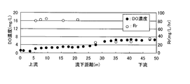
- FIG. 5 shows a treatment tank in which a plurality of membrane separation devices are immersed from the upstream side to the downstream side, with the amount of air diffused to each membrane separation device kept constant, and dissolution with respect to the flow distance of the water to be treated.
- required the relationship between oxygen concentration DO and oxygen utilization rate Rr by measurement is shown.
- the dissolved oxygen concentration increases as a whole from the upstream side toward the downstream side, and conversely, the oxygen utilization rate Rr tends to decrease. It can be presumed that biological treatment is actively performed on the upstream side where the water content is high, and that biological treatment is gentle on the downstream side where the concentration of organic substances in the water to be treated is low. Moreover, it can be estimated that the concentration of the metabolite of the microorganism which becomes a causative substance of fouling etc. is also increasing on the upstream side where biological treatment is actively performed.
- the dissolved oxygen concentration does not increase with a certain slope from the upstream side to the downstream side of the treatment tank, and its fluctuation range varies, and it varies greatly depending on the state and temperature of the water to be treated. May fluctuate.
- the object of the present invention is immersed in the treatment tank by adjusting the amount of diffused air and the flow rate of the permeate according to the actual state of the water to be treated at that time inside the treatment tank.
- Another object of the present invention is to provide an organic wastewater treatment apparatus operating method and an organic wastewater treatment apparatus that can effectively prevent fouling of the entire membrane separation apparatus.
- the first characteristic configuration of the operation method of the organic waste water treatment apparatus according to the present invention is as described in claim 1 of the claims.
- the sludge property measuring means measures the sludge property for each of the divided treatment layer areas, and the amount of air diffused and / or permeate is appropriate for the corresponding membrane separation device based on the measured value. Since the flow rate is adjusted, even if the sludge has various properties in each area, fouling of the entire membrane separation apparatus can be avoided and an appropriate permeate flow rate can be secured.
- the sludge property measuring means is constituted by a dissolved oxygen content measuring means, and the dissolved oxygen content measuring means is The area where the measured amount of dissolved oxygen is lower is that the amount of air diffused and / or the permeate flow rate is set lower for the membrane separation device immersed in the corresponding area.
- the third characteristic configuration is the amount of aeration and / or permeate flow rate in the entire organic wastewater treatment apparatus in addition to the first or second characteristic configuration described above.
- Membrane separation device in specific area while keeping fluctuation of overall energy cost and fluctuation of permeate flow rate by keeping constant the amount of diffused air and / or total permeate flow rate in organic wastewater treatment equipment By increasing the amount of air diffused or reducing the permeate flow rate, fouling can be prevented as a whole.
- the first characteristic configuration of the organic waste water treatment apparatus is the treatment tank to which the water to be treated is supplied, the air diffuser for cleaning the membrane surface, and the membrane surface, as described in claim 4.
- a plurality of membrane separation devices provided with a permeate extraction means for extracting a permeate and immersed in the water to be treated in the treatment tank; a plurality of sludge property measurement means for measuring sludge properties distributed in the treatment tank; Based on the measured value of the sludge property measuring means, the amount of air diffused from the air diffuser and / or the permeate flow rate from the permeate takeout means provided in the membrane separation device arranged in the vicinity of the sludge property measuring means Control means for setting.
- the control means the amount of air diffused from the air diffuser and / or the flow rate of the permeate from the permeate takeout means corresponding to the actual sludge properties measured by the sludge property measuring means is provided. Therefore, even if the sludge has various properties, it is possible to realize an organic wastewater treatment apparatus capable of ensuring an appropriate permeate flow rate by avoiding fouling of the entire membrane separation apparatus.
- the sludge property measuring means is constituted by a dissolved oxygen amount measuring means, and the control means is the dissolved oxygen.
- the amount of dissolved oxygen measured by the amount measuring means becomes smaller than a set value, a large amount of air diffused from the air diffuser provided in the membrane separation device arranged in the vicinity of the dissolved oxygen amount measuring means is set and / or Alternatively, the permeate flow rate is set low.
- control means can adjust the opening of the valve for flow rate adjustment or the electric motor for flow rate adjustment.
- the amount of air diffused and / or the permeate flow rate for each membrane separation device is set by the inverter control.
- a flow rate adjusting valve and an electric motor inverter are suitable. It can be easily adjusted, and by adjusting the output frequency of the inverter, it is possible to adjust the air flow rate by the blower fan and the suction pressure of the permeate by the pump.
- the film immersed in the treatment tank is adjusted by adjusting the amount of diffused air and the flow rate of the permeate according to the actual state of the water to be treated at that time inside the treatment tank.
- An organic wastewater treatment device operating method and an organic wastewater treatment device that can effectively prevent fouling of the entire separation device can be provided.
- FIG. 1 is an explanatory diagram of a sewage treatment apparatus.
- FIG. 2 is an explanatory diagram of the membrane separation apparatus.
- FIG. 3 is an explanatory diagram of the membrane element.
- FIG. 4A is a view of a general sewage treatment apparatus as viewed from above, and
- FIG. 4B is a view of a similar apparatus as viewed from the side.
- FIG. 5 is a characteristic diagram of dissolved oxygen concentration DO and oxygen utilization rate Rr with respect to the flow distance of the water to be treated in a treatment tank having a long flow distance and a constant amount of air diffused.
- FIG. 6 is an explanatory view of a membrane separation apparatus according to the present invention.
- FIG. 1 shows an example of an organic wastewater treatment device 1 in which a membrane separation device 6 is incorporated.
- Pretreatment equipment 2 flow rate adjustment tank 3, activated sludge treatment tank 4 consisting of anaerobic tank 4a and membrane separation tank 4b filled with activated sludge, and water to be treated in the tank disposed immersed in membrane separation tank 4b
- a membrane separation device 6 that obtains permeated water, a treated water tank 5 that receives treated water filtered by the membrane separation device 6, and a control device 20 as control means.
- the pretreatment facility 2 is provided with a bar screen 2a and the like for removing contaminants mixed in the raw water, and the water to be treated from which the contaminants have been removed by the bar screen 2a and the like is temporarily stored in the flow rate adjusting tank 3.
- the flow rate adjusting mechanism 3a such as a pump or a valve is configured to stably supply the water to be treated at a constant flow rate from the flow rate adjusting tank 3 to the activated sludge treatment tank 4. Has been.
- the membrane separation tank 4b filled with activated sludge organic substances in the raw water are decomposed by biological treatment with activated sludge, and the permeated water filtered through the membrane separator 6 is led to the treated water tank 5 and temporarily stored. And then released. A part of the water to be treated in the membrane separation tank 4b is pulled out by the return pump and returned to the anaerobic tank 4a through the return path 4c. Excess sludge grown in the membrane separation tank 4b is pulled out of the tank and discarded, and is kept at a constant sludge concentration.
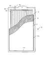
- the membrane separation apparatus 6 includes 100 plate-like membrane elements 8 in a membrane case 7 that is open at the top and bottom so that each membrane surface is in a vertical posture and about 6 mm to 10 mm. (In this embodiment, 8 mm) are arranged at regular intervals, and a diffuser 12 is provided below the membrane case 7.
- the air diffuser 12 includes an air diffuser 13 formed with a plurality of air diffuser holes, and an air supply source 15 such as a blower B or a compressor installed outside the tank via an air diffuser header 14 connected to the air diffuser 13. It is connected.
- an air supply source 15 such as a blower B or a compressor installed outside the tank via an air diffuser header 14 connected to the air diffuser 13. It is connected.
- a pump 18 serving as a suction mechanism installed outside the tank is connected to the membrane element 8 via a water collecting pipe 17, and the water to be treated in the tank is suction filtered so as to pass through the membrane surface of the membrane element 8.
- the membrane element 8 has separation membranes 11 disposed on both front and back surfaces of a resin membrane support 9 having a length of 1000 mm ⁇ width of 490 mm via spacers 10. 11a is adhered to the membrane support 9 with ultrasonic waves or heat, or is bonded using an adhesive or the like.
- the separation membrane 11 is a microporous membrane having an average pore diameter of about 0.2 ⁇ m, and is an organic filtration membrane in which a nonwoven fabric is coated and impregnated with a porous resin.
- the membrane element 8 is not limited to such a configuration, and the separation membrane 11 is disposed so as to be wound on both the front and back surfaces of the membrane support 9, and the end portion of the separation membrane 11 is bonded or welded. Also good.
- a plurality of groove portions 9b having a depth of about 2 mm and a width of about 2 mm are formed on the surface of the membrane support 9 along the longitudinal direction, and a horizontal groove portion 9c that communicates with each groove portion 9b is formed at the upper end portion thereof.
- Horizontal groove portions 9 c formed on the front and back surfaces are communicated with each other through a communication hole 9 d and communicated with a nozzle 9 a formed on the upper edge portion of the membrane support 9.
- each nozzle 9 a is connected to a water collecting pipe 17 through a tube 16, and a pump 18 as a suction mechanism is connected to the water collecting pipe 17, and the permeated water sucked by the pump 18 is treated water tank. It is comprised so that it may be transferred to 5.
- the filtration step of obtaining the permeated water in which the water to be treated has permeated the separation membrane 11 is performed by operating the air diffuser 12 and the suction mechanism 18 of the membrane separation device 6.
- a plurality of membrane separation devices 6 are soaked in the flow direction of the water to be treated, and an example of the sludge property measuring means at predetermined intervals along the flow direction of the water to be treated.
- the dissolved oxygen amount measuring means S is installed, and the dissolved oxygen amount measured by each dissolved oxygen amount measuring means S is input to the control device 20.
- the control device 20 includes a valve drive circuit that adjusts the opening of a valve provided in a predetermined water collecting pipe 17 connected to a pump 18 serving as a suction mechanism, and a predetermined air diffuser 12 from a blower B that is an air supply source 15.
- the valve drive circuit which adjusts the opening degree of the valve
- the air diffuser 12 functions as an air diffuser that cleans the membrane surface
- the suction mechanism 18 functions as a permeate extractor that extracts the permeate that has permeated through the membrane surface
- the dissolved oxygen amount measuring unit S serves as the treatment tank 4b. It functions as a plurality of sludge property measuring means that are dispersed and arranged to measure the sludge property.
- the fouling of the entire membrane separation apparatus 6 immersed in the treatment tank is effective. It is very important to operate so as to ensure a constant permeate flow rate while preventing it.
- the above-described control device 20 divides the membrane separation tank 4b, which is a treatment tank, into a plurality of areas along the arrangement direction of the membrane separation apparatus 6, and based on the measurement values of the sludge property measuring means arranged in each area. Thus, the amount of air diffused and the flow rate of the permeate are set for the membrane separation device 6 immersed in the corresponding area.
- the membrane separation tank 4b is divided into four sections R1 to R4 from upstream to downstream, and dissolved oxygen amount measuring means S1 to S4, which are sludge property measuring means, are installed in the respective sections R1 to R4.
- dissolved oxygen amount measuring means S1 to S4 which are sludge property measuring means
- An example is shown in which a plurality of membrane separation devices 6 installed in each of the sections R1 to R4 are grouped.
- Valves V11 to V14 for adjusting the permeate flow rate are installed in the connecting portions of the water collecting pipes of the grouped membrane separation devices 6, and the amount of air diffused is adjusted in the connecting portions of the air supply pipes 14 provided in the respective air diffusers 12.
- Valves V21 to V24 are provided.
- the control device 20 measures the dissolved oxygen amount, which is an example of the property of sludge, by the dissolved oxygen amount measuring means S1 to S4 for each of the sections R1 to R4 of the treatment layer divided into a plurality of portions, and takes a corresponding action based on the measured value.
- the appropriate amount of diffused air and permeate flow rate for the membrane separator 6 for each zone fouling of the entire membrane separator can be avoided even if the sludge properties vary in each zone R1 to R4. And control to ensure an appropriate permeate flow rate.
- an appropriate total amount of diffused air required for the membrane separation tank 4b is set for the BOD / SS load of the raw water assumed in advance, and the control device 20 determines the total amount of diffused air for each zone.
- the degree of opening of the valves V21 to V24 is set so that the amount of air diffused evenly is the amount of air diffused supplied from the membrane separation device 6 installed in each zone.
- control device 20 adjusts the permeate flow rate so that a permeate flow rate obtained by equally distributing the preset total permeate flow rate in each area can be obtained from the membrane separation device 6 installed in each area.
- the opening degree of each valve V11 to V14 is set.
- control device 20 inputs the measured values of the dissolved oxygen amount measuring means S1 to S4 every predetermined time (for example, 3 hours), and based on the value, the area where the dissolved oxygen amount is lower is immersed in the corresponding area. Further, the opening degree of each of the valves V21 to V24 and V11 to V14 is adjusted so that the amount of air diffused to the membrane separation device 6 is set to be large and the permeate flow rate is set to be small.
- each valve V21 to V24 is adjusted so that the ratio of the measured value of the dissolved oxygen amount in each area and the ratio of the amount of diffused air in each area are approximately inversely proportional, and the dissolved oxygen amount in each area is adjusted.
- the opening degree of each valve V11 to V14 can be adjusted so that the ratio of the measured value is proportional to the ratio of the permeate flow rate in each zone.
- the opening degree of each valve V21 to V24 is adjusted so that a value obtained by multiplying the deviation of the measured value of the dissolved oxygen amount in each zone from the average value by a predetermined aeration amount correction coefficient becomes the aeration amount in each zone.
- the opening degree of each of the valves V11 to V14 can be adjusted so that a value obtained by multiplying a deviation from the average value by a predetermined permeate flow rate correction coefficient becomes a permeate flow rate in each zone.
- the aeration amount correction coefficient is a negative value, and the aeration amount increases when the deviation becomes negative, and the aeration amount decreases when the deviation becomes positive.
- the permeate flow rate correction coefficient is a positive value, and is set so that the permeate flow rate decreases when the deviation becomes negative, and the permeate flow rate increases when the deviation becomes positive.
- the opening degree of each of the valves V21 to V24 and V11 to V14 can be adjusted based on the value of a correction table set in advance according to the deviation of the measured value of the dissolved oxygen amount in each zone from the average value.
- the time interval for inputting the measurement values of the dissolved oxygen amount measuring means S1 to S4 is not particularly limited, and is a value set as appropriate.
- the film immersed in the corresponding area is arranged.
- the aeration amount and / or the permeate flow rate for the separation apparatus are set.
- an appropriate aeration amount and The total aeration amount and the total permeate flow rate are variably set so as to be the permeate flow rate, and the aeration amount and the permeate flow rate in each area are allocated to the variably set total aeration amount and total permeate flow rate. May be adjusted. Also in this case, the distribution can be adjusted in the same manner as described above.
- the membrane surface is cleaned by increasing the amount of aeration of the membrane separator in that area, and the area.
- the permeate flow rate of the membrane separator is reduced to suppress the adsorption of fouling substances to the membrane surface, effectively preventing fouling of all membrane separators in the tank and stable for a long time It is an invention that aims to be operated.
- the amount of aeration and permeate flow rate controlled by the control device 20 is not a control of feedback control in order to converge to a target sludge property, here, a dissolved oxygen amount, but fouling is only prevented.
- the purpose of this is to control open loop.
- the total diffused gas total amount and the total permeate flow rate are variably set so as to obtain an appropriate total diffused gas amount and permeate flow rate based on the average value of the measured values of the dissolved oxygen amount measuring means S1 to S4
- the total aeration amount and the total permeate flow rate are preferably feedback controlled.
- PID control can be suitably used.
- control device 20 has described the aspect in which both the amount of diffused air and the flow rate of the permeate are controlled based on the measured value of the dissolved oxygen amount in each area. However, in the aspect in which only one of them is controlled. Good.
- the control device 20 diffuses from the aeration means provided in the membrane separation device disposed in the vicinity of the dissolved oxygen amount measuring means.
- the air volume may be set higher or the permeate flow rate may be set lower.
- the other side that is not the control target only needs to maintain the initial set state.
- the other that is not to be controlled may be controlled independently of the above based on another index.
- oxygen utilization rate As an index of sludge properties, oxygen utilization rate, ORP, COD, etc. can be used in addition to the dissolved oxygen amount.
- those indicators are not limited to the mode of automatic measurement by a sensor, but may be a mode in which a supervisor manually measures and inputs the value to the input unit of the control device 20.
- a mode in which the monitoring person manually operates the operation unit of the control device 20 may be employed.
- the specific configuration of the control device 20 is not particularly limited, and can be realized in various modes such as electronic control using a computer and remote control using a sequencer.
- the blower fan B and the pump P are installed, and the control device 20 adjusts the amount of diffused air and the flow rate of the permeate by adjusting the rotation speed of the motor built in each blower fan B and the pump P through an inverter circuit.
- the present invention has been described in an aspect in which an elongated treatment tank is divided into a plurality of areas in the flow direction when a biological treatment tank of an existing sewage treatment apparatus is remodeled into a membrane separation tank.
- the invention is not limited to such a long and narrow processing tank, but can be applied to a processing tank that is wide in the width direction.
- the treatment tank is divided into a plurality of areas vertically and horizontally in a plan view, and based on the measured values of the sludge property measuring means disposed in each area, the dispersion to the membrane separation apparatus immersed in the corresponding area is dispersed.
- the air volume and / or the permeate flow rate may be set.
- Membrane separator 4a Anaerobic tank 4b: Membrane separator 6: Membrane separator 12: Air diffuser 15: Air supply source (blower) 18: Suction mechanism (pump) 20: Control device
Landscapes
- Life Sciences & Earth Sciences (AREA)
- Engineering & Computer Science (AREA)
- Chemical & Material Sciences (AREA)
- Water Supply & Treatment (AREA)
- Hydrology & Water Resources (AREA)
- Environmental & Geological Engineering (AREA)
- Microbiology (AREA)
- Biodiversity & Conservation Biology (AREA)
- Organic Chemistry (AREA)
- Chemical Kinetics & Catalysis (AREA)
- Health & Medical Sciences (AREA)
- Molecular Biology (AREA)
- Separation Using Semi-Permeable Membranes (AREA)
- Activated Sludge Processes (AREA)
Priority Applications (4)
| Application Number | Priority Date | Filing Date | Title |
|---|---|---|---|
| EP14773974.2A EP2980029B1 (de) | 2013-03-27 | 2014-03-27 | Betriebsverfahren für eine vorrichtung zur behandlung organischer abwässer und vorrichtung zur behandlung organischer abwässer |
| CN201480004084.4A CN104903255A (zh) | 2013-03-27 | 2014-03-27 | 有机排水处理装置的运转方法及有机排水处理装置 |
| US14/866,647 US20160016833A1 (en) | 2013-03-27 | 2015-09-25 | Operating method for organic wastewater treatment device and organic wastewater treatment device |
| HRP20182086TT HRP20182086T1 (hr) | 2013-03-27 | 2018-12-11 | Postupak za upravljanje uređajem za pročišćavanje organskih otpadnih voda i uređaj za pročišćavanje organskih otpadnih voda |
Applications Claiming Priority (2)
| Application Number | Priority Date | Filing Date | Title |
|---|---|---|---|
| JP2013-066065 | 2013-03-27 | ||
| JP2013066065A JP6027474B2 (ja) | 2013-03-27 | 2013-03-27 | 有機性排水処理装置の運転方法及び有機性排水処理装置 |
Related Child Applications (1)
| Application Number | Title | Priority Date | Filing Date |
|---|---|---|---|
| US14/866,647 Continuation US20160016833A1 (en) | 2013-03-27 | 2015-09-25 | Operating method for organic wastewater treatment device and organic wastewater treatment device |
Publications (1)
| Publication Number | Publication Date |
|---|---|
| WO2014157488A1 true WO2014157488A1 (ja) | 2014-10-02 |
Family
ID=51624450
Family Applications (1)
| Application Number | Title | Priority Date | Filing Date |
|---|---|---|---|
| PCT/JP2014/058789 WO2014157488A1 (ja) | 2013-03-27 | 2014-03-27 | 有機性排水処理装置の運転方法及び有機性排水処理装置 |
Country Status (7)
| Country | Link |
|---|---|
| US (1) | US20160016833A1 (de) |
| EP (1) | EP2980029B1 (de) |
| JP (1) | JP6027474B2 (de) |
| CN (1) | CN104903255A (de) |
| HR (1) | HRP20182086T1 (de) |
| TR (1) | TR201900270T4 (de) |
| WO (1) | WO2014157488A1 (de) |
Cited By (4)
| Publication number | Priority date | Publication date | Assignee | Title |
|---|---|---|---|---|
| CN104923040A (zh) * | 2015-05-27 | 2015-09-23 | 中国石油化工股份有限公司 | 膜法油气回收分组控制装置及其使用方法 |
| US9333464B1 (en) | 2014-10-22 | 2016-05-10 | Koch Membrane Systems, Inc. | Membrane module system with bundle enclosures and pulsed aeration and method of operation |
| USD779631S1 (en) | 2015-08-10 | 2017-02-21 | Koch Membrane Systems, Inc. | Gasification device |
| US10720271B2 (en) | 2016-09-26 | 2020-07-21 | Shin-Etsu Chemical Co., Ltd. | R-Fe-B sintered magnet |
Families Citing this family (6)
| Publication number | Priority date | Publication date | Assignee | Title |
|---|---|---|---|---|
| KR101367155B1 (ko) * | 2012-01-09 | 2014-02-26 | 두산중공업 주식회사 | 여과막 오염 지수 측정 장치 |
| CN106823820B (zh) * | 2017-03-03 | 2021-02-02 | 同济大学 | 一种获得金属膜运行和清洗工况参数的一体化装置 |
| JP6883459B2 (ja) * | 2017-04-04 | 2021-06-09 | 株式会社クボタ | 有機性排水処理方法及び有機性排水処理装置 |
| JP6740475B2 (ja) | 2018-03-27 | 2020-08-12 | 三菱ケミカルアクア・ソリューションズ株式会社 | ヘッダー付散気装置及び膜分離活性汚泥装置 |
| CN108751401B (zh) * | 2018-06-22 | 2020-12-22 | 北京碧水源科技股份有限公司 | 一种mbr联合工艺鼓风系统及其运行方法 |
| JP2023031329A (ja) * | 2021-08-25 | 2023-03-09 | 株式会社クボタ | 水処理装置、水処理装置における生物膜の洗浄方法、水処理装置における生物膜の膜厚評価方法 |
Citations (11)
| Publication number | Priority date | Publication date | Assignee | Title |
|---|---|---|---|---|
| JPH11333490A (ja) * | 1998-05-22 | 1999-12-07 | Toto Ltd | 膜浸漬型ろ過装置の運転方法 |
| JP2000312898A (ja) | 1999-04-28 | 2000-11-14 | Sumitomo Heavy Ind Ltd | 排水処理装置及び方法 |
| JP2001170670A (ja) * | 1999-12-17 | 2001-06-26 | Kubota Corp | 濃縮機能付き膜分離活性汚泥方式の曝気槽 |
| JP2001353497A (ja) * | 2000-06-14 | 2001-12-25 | Kubota Corp | 移動式膜分離ユニット |
| JP2002126460A (ja) | 2000-10-19 | 2002-05-08 | Japan Organo Co Ltd | 膜濾過装置 |
| JP2002210484A (ja) * | 2001-01-22 | 2002-07-30 | Sumitomo Heavy Ind Ltd | 有機性排水の処理方法及び装置 |
| JP2003275759A (ja) * | 2002-03-20 | 2003-09-30 | Hitachi Plant Eng & Constr Co Ltd | 水処理装置 |
| JP2004237202A (ja) * | 2003-02-05 | 2004-08-26 | Hitachi Plant Eng & Constr Co Ltd | 膜分離式活性汚泥処理装置 |
| JP2007152282A (ja) * | 2005-12-07 | 2007-06-21 | Mitsubishi Rayon Eng Co Ltd | 膜分離活性汚泥処理方法 |
| WO2008139618A1 (ja) | 2007-05-14 | 2008-11-20 | Mitsubishi Rayon Engineering Co., Ltd. | 水の処理方法 |
| JP2009279508A (ja) * | 2008-05-21 | 2009-12-03 | Nissin Electric Co Ltd | 排水処理方法およびそれに用いる計装制御装置、排水処理設備 |
Family Cites Families (6)
| Publication number | Priority date | Publication date | Assignee | Title |
|---|---|---|---|---|
| AU2012200338B2 (en) * | 2005-07-12 | 2014-03-20 | Zenon Technology Partnership | Process control for an immersed membrane system |
| JP5448287B2 (ja) * | 2006-01-19 | 2014-03-19 | 三菱レイヨン株式会社 | 膜分離活性汚泥処理装置 |
| CN201648184U (zh) * | 2010-03-10 | 2010-11-24 | 诺卫环境安全工程技术(广州)有限公司 | 一种用于海上平台或船舶的生活污水处理系统 |
| US20120285874A1 (en) * | 2010-06-30 | 2012-11-15 | National University Corporation Hokkaido University | Immersion type membrane module unit and membrane separation activated sludge process equipment |
| US20120187048A1 (en) * | 2011-01-25 | 2012-07-26 | Enviro-Mix, Llc | Systems and methods for scouring membrane bioreactors |
| KR101068205B1 (ko) * | 2011-03-04 | 2011-09-28 | 박병선 | 파울링 저감을 위한 mbr조 어셈블리 |
-
2013
- 2013-03-27 JP JP2013066065A patent/JP6027474B2/ja active Active
-
2014
- 2014-03-27 TR TR2019/00270T patent/TR201900270T4/tr unknown
- 2014-03-27 WO PCT/JP2014/058789 patent/WO2014157488A1/ja active Application Filing
- 2014-03-27 CN CN201480004084.4A patent/CN104903255A/zh active Pending
- 2014-03-27 EP EP14773974.2A patent/EP2980029B1/de active Active
-
2015
- 2015-09-25 US US14/866,647 patent/US20160016833A1/en not_active Abandoned
-
2018
- 2018-12-11 HR HRP20182086TT patent/HRP20182086T1/hr unknown
Patent Citations (11)
| Publication number | Priority date | Publication date | Assignee | Title |
|---|---|---|---|---|
| JPH11333490A (ja) * | 1998-05-22 | 1999-12-07 | Toto Ltd | 膜浸漬型ろ過装置の運転方法 |
| JP2000312898A (ja) | 1999-04-28 | 2000-11-14 | Sumitomo Heavy Ind Ltd | 排水処理装置及び方法 |
| JP2001170670A (ja) * | 1999-12-17 | 2001-06-26 | Kubota Corp | 濃縮機能付き膜分離活性汚泥方式の曝気槽 |
| JP2001353497A (ja) * | 2000-06-14 | 2001-12-25 | Kubota Corp | 移動式膜分離ユニット |
| JP2002126460A (ja) | 2000-10-19 | 2002-05-08 | Japan Organo Co Ltd | 膜濾過装置 |
| JP2002210484A (ja) * | 2001-01-22 | 2002-07-30 | Sumitomo Heavy Ind Ltd | 有機性排水の処理方法及び装置 |
| JP2003275759A (ja) * | 2002-03-20 | 2003-09-30 | Hitachi Plant Eng & Constr Co Ltd | 水処理装置 |
| JP2004237202A (ja) * | 2003-02-05 | 2004-08-26 | Hitachi Plant Eng & Constr Co Ltd | 膜分離式活性汚泥処理装置 |
| JP2007152282A (ja) * | 2005-12-07 | 2007-06-21 | Mitsubishi Rayon Eng Co Ltd | 膜分離活性汚泥処理方法 |
| WO2008139618A1 (ja) | 2007-05-14 | 2008-11-20 | Mitsubishi Rayon Engineering Co., Ltd. | 水の処理方法 |
| JP2009279508A (ja) * | 2008-05-21 | 2009-12-03 | Nissin Electric Co Ltd | 排水処理方法およびそれに用いる計装制御装置、排水処理設備 |
Non-Patent Citations (1)
| Title |
|---|
| See also references of EP2980029A4 |
Cited By (8)
| Publication number | Priority date | Publication date | Assignee | Title |
|---|---|---|---|---|
| US9333464B1 (en) | 2014-10-22 | 2016-05-10 | Koch Membrane Systems, Inc. | Membrane module system with bundle enclosures and pulsed aeration and method of operation |
| US9956530B2 (en) | 2014-10-22 | 2018-05-01 | Koch Membrane Systems, Inc. | Membrane module system with bundle enclosures and pulsed aeration and method of operation |
| US10702831B2 (en) | 2014-10-22 | 2020-07-07 | Koch Separation Solutions, Inc. | Membrane module system with bundle enclosures and pulsed aeration and method of operation |
| CN104923040A (zh) * | 2015-05-27 | 2015-09-23 | 中国石油化工股份有限公司 | 膜法油气回收分组控制装置及其使用方法 |
| USD779631S1 (en) | 2015-08-10 | 2017-02-21 | Koch Membrane Systems, Inc. | Gasification device |
| USD779632S1 (en) | 2015-08-10 | 2017-02-21 | Koch Membrane Systems, Inc. | Bundle body |
| US10720271B2 (en) | 2016-09-26 | 2020-07-21 | Shin-Etsu Chemical Co., Ltd. | R-Fe-B sintered magnet |
| US11410805B2 (en) | 2016-09-26 | 2022-08-09 | Shin-Etsu Chemical Co., Ltd. | R-Fe-B sintered magnet |
Also Published As
| Publication number | Publication date |
|---|---|
| CN104903255A (zh) | 2015-09-09 |
| TR201900270T4 (tr) | 2019-02-21 |
| EP2980029B1 (de) | 2018-11-21 |
| HRP20182086T1 (hr) | 2019-02-08 |
| US20160016833A1 (en) | 2016-01-21 |
| EP2980029A1 (de) | 2016-02-03 |
| EP2980029A4 (de) | 2016-11-16 |
| JP2014188442A (ja) | 2014-10-06 |
| JP6027474B2 (ja) | 2016-11-16 |
Similar Documents
| Publication | Publication Date | Title |
|---|---|---|
| JP6027474B2 (ja) | 有機性排水処理装置の運転方法及び有機性排水処理装置 | |
| JP5822264B2 (ja) | 膜分離活性汚泥処理装置の運転方法 | |
| KR101050374B1 (ko) | 소규모 하수처리시설의 자동 운전장치 | |
| JP2008264772A (ja) | 膜分離活性汚泥装置及び有機物含有水の処理方法 | |
| US11053150B2 (en) | Wastewater treatment system and method | |
| JP4059790B2 (ja) | 膜分離活性汚泥処理装置及び膜分離活性汚泥処理方法 | |
| US20210179462A1 (en) | Method for treating organic wastewater, and device for treating organc wastewater | |
| US10822260B2 (en) | Organic wastewater treatment method and organic wastewater treatment device | |
| JP2006255534A (ja) | ろ過膜の洗浄方法 | |
| JP2001334285A (ja) | 有機性排水の生物処理装置 | |
| JP5080739B2 (ja) | 活性汚泥処理装置 | |
| WO2016178366A1 (ja) | 膜分離活性汚泥処理方法及び膜分離活性汚泥処理システム | |
| JP2020097023A (ja) | 排水の処理方法および排水の処理システム | |
| KR20150093409A (ko) | 멤브레인 세정방법 | |
| JP5712453B2 (ja) | 排水処理装置 | |
| JP3722084B2 (ja) | 膜分離排水処理方法および装置 | |
| JP2012000584A (ja) | エアリフトポンプ装置及び汚水処理設備 | |
| KR20030097075A (ko) | 생물막활성탄과 마이크로필터모듈을 이용한 오·폐수고도처리장치 | |
| WO2015002121A1 (ja) | 汚水浄化処理方法及び汚水浄化処理装置 | |
| JP5016827B2 (ja) | 膜分離活性汚泥処理方法 | |
| WO2023106000A1 (ja) | 有機性排水処理装置及び有機性排水処理装置の運転方法 | |
| JP2012071238A (ja) | オゾン供給装置 | |
| JP2007167774A (ja) | 活性汚泥処理装置 | |
| JP6775364B2 (ja) | 汚水処理設備及び汚水処理方法 | |
| JP6475580B2 (ja) | 活性汚泥処理装置 |
Legal Events
| Date | Code | Title | Description |
|---|---|---|---|
| 121 | Ep: the epo has been informed by wipo that ep was designated in this application |
Ref document number: 14773974 Country of ref document: EP Kind code of ref document: A1 |
|
| WWE | Wipo information: entry into national phase |
Ref document number: 2014773974 Country of ref document: EP |
|
| NENP | Non-entry into the national phase |
Ref country code: DE |