WO2014156671A1 - Feuille d'acier plaquée à résistance élevée pour un élément structural soudé et procédé de fabrication de ladite feuille - Google Patents
Feuille d'acier plaquée à résistance élevée pour un élément structural soudé et procédé de fabrication de ladite feuille Download PDFInfo
- Publication number
- WO2014156671A1 WO2014156671A1 PCT/JP2014/056620 JP2014056620W WO2014156671A1 WO 2014156671 A1 WO2014156671 A1 WO 2014156671A1 JP 2014056620 W JP2014056620 W JP 2014056620W WO 2014156671 A1 WO2014156671 A1 WO 2014156671A1
- Authority
- WO
- WIPO (PCT)
- Prior art keywords
- steel sheet
- phase
- plated steel
- less
- steel
- Prior art date
Links
Images


Classifications
-
- C—CHEMISTRY; METALLURGY
- C23—COATING METALLIC MATERIAL; COATING MATERIAL WITH METALLIC MATERIAL; CHEMICAL SURFACE TREATMENT; DIFFUSION TREATMENT OF METALLIC MATERIAL; COATING BY VACUUM EVAPORATION, BY SPUTTERING, BY ION IMPLANTATION OR BY CHEMICAL VAPOUR DEPOSITION, IN GENERAL; INHIBITING CORROSION OF METALLIC MATERIAL OR INCRUSTATION IN GENERAL
- C23C—COATING METALLIC MATERIAL; COATING MATERIAL WITH METALLIC MATERIAL; SURFACE TREATMENT OF METALLIC MATERIAL BY DIFFUSION INTO THE SURFACE, BY CHEMICAL CONVERSION OR SUBSTITUTION; COATING BY VACUUM EVAPORATION, BY SPUTTERING, BY ION IMPLANTATION OR BY CHEMICAL VAPOUR DEPOSITION, IN GENERAL
- C23C2/00—Hot-dipping or immersion processes for applying the coating material in the molten state without affecting the shape; Apparatus therefor
- C23C2/04—Hot-dipping or immersion processes for applying the coating material in the molten state without affecting the shape; Apparatus therefor characterised by the coating material
- C23C2/06—Zinc or cadmium or alloys based thereon
-
- B—PERFORMING OPERATIONS; TRANSPORTING
- B32—LAYERED PRODUCTS
- B32B—LAYERED PRODUCTS, i.e. PRODUCTS BUILT-UP OF STRATA OF FLAT OR NON-FLAT, e.g. CELLULAR OR HONEYCOMB, FORM
- B32B15/00—Layered products comprising a layer of metal
- B32B15/01—Layered products comprising a layer of metal all layers being exclusively metallic
- B32B15/013—Layered products comprising a layer of metal all layers being exclusively metallic one layer being formed of an iron alloy or steel, another layer being formed of a metal other than iron or aluminium
-
- C—CHEMISTRY; METALLURGY
- C21—METALLURGY OF IRON
- C21D—MODIFYING THE PHYSICAL STRUCTURE OF FERROUS METALS; GENERAL DEVICES FOR HEAT TREATMENT OF FERROUS OR NON-FERROUS METALS OR ALLOYS; MAKING METAL MALLEABLE, e.g. BY DECARBURISATION OR TEMPERING
- C21D8/00—Modifying the physical properties by deformation combined with, or followed by, heat treatment
- C21D8/02—Modifying the physical properties by deformation combined with, or followed by, heat treatment during manufacturing of plates or strips
- C21D8/0221—Modifying the physical properties by deformation combined with, or followed by, heat treatment during manufacturing of plates or strips characterised by the working steps
- C21D8/0236—Cold rolling
-
- C—CHEMISTRY; METALLURGY
- C21—METALLURGY OF IRON
- C21D—MODIFYING THE PHYSICAL STRUCTURE OF FERROUS METALS; GENERAL DEVICES FOR HEAT TREATMENT OF FERROUS OR NON-FERROUS METALS OR ALLOYS; MAKING METAL MALLEABLE, e.g. BY DECARBURISATION OR TEMPERING
- C21D8/00—Modifying the physical properties by deformation combined with, or followed by, heat treatment
- C21D8/02—Modifying the physical properties by deformation combined with, or followed by, heat treatment during manufacturing of plates or strips
- C21D8/0247—Modifying the physical properties by deformation combined with, or followed by, heat treatment during manufacturing of plates or strips characterised by the heat treatment
- C21D8/0263—Modifying the physical properties by deformation combined with, or followed by, heat treatment during manufacturing of plates or strips characterised by the heat treatment following hot rolling
-
- C—CHEMISTRY; METALLURGY
- C21—METALLURGY OF IRON
- C21D—MODIFYING THE PHYSICAL STRUCTURE OF FERROUS METALS; GENERAL DEVICES FOR HEAT TREATMENT OF FERROUS OR NON-FERROUS METALS OR ALLOYS; MAKING METAL MALLEABLE, e.g. BY DECARBURISATION OR TEMPERING
- C21D8/00—Modifying the physical properties by deformation combined with, or followed by, heat treatment
- C21D8/02—Modifying the physical properties by deformation combined with, or followed by, heat treatment during manufacturing of plates or strips
- C21D8/0278—Modifying the physical properties by deformation combined with, or followed by, heat treatment during manufacturing of plates or strips involving a particular surface treatment
-
- C—CHEMISTRY; METALLURGY
- C21—METALLURGY OF IRON
- C21D—MODIFYING THE PHYSICAL STRUCTURE OF FERROUS METALS; GENERAL DEVICES FOR HEAT TREATMENT OF FERROUS OR NON-FERROUS METALS OR ALLOYS; MAKING METAL MALLEABLE, e.g. BY DECARBURISATION OR TEMPERING
- C21D9/00—Heat treatment, e.g. annealing, hardening, quenching or tempering, adapted for particular articles; Furnaces therefor
- C21D9/46—Heat treatment, e.g. annealing, hardening, quenching or tempering, adapted for particular articles; Furnaces therefor for sheet metals
-
- C—CHEMISTRY; METALLURGY
- C22—METALLURGY; FERROUS OR NON-FERROUS ALLOYS; TREATMENT OF ALLOYS OR NON-FERROUS METALS
- C22C—ALLOYS
- C22C18/00—Alloys based on zinc
- C22C18/04—Alloys based on zinc with aluminium as the next major constituent
-
- C—CHEMISTRY; METALLURGY
- C22—METALLURGY; FERROUS OR NON-FERROUS ALLOYS; TREATMENT OF ALLOYS OR NON-FERROUS METALS
- C22C—ALLOYS
- C22C38/00—Ferrous alloys, e.g. steel alloys
-
- C—CHEMISTRY; METALLURGY
- C22—METALLURGY; FERROUS OR NON-FERROUS ALLOYS; TREATMENT OF ALLOYS OR NON-FERROUS METALS
- C22C—ALLOYS
- C22C38/00—Ferrous alloys, e.g. steel alloys
- C22C38/001—Ferrous alloys, e.g. steel alloys containing N
-
- C—CHEMISTRY; METALLURGY
- C22—METALLURGY; FERROUS OR NON-FERROUS ALLOYS; TREATMENT OF ALLOYS OR NON-FERROUS METALS
- C22C—ALLOYS
- C22C38/00—Ferrous alloys, e.g. steel alloys
- C22C38/002—Ferrous alloys, e.g. steel alloys containing In, Mg, or other elements not provided for in one single group C22C38/001 - C22C38/60
-
- C—CHEMISTRY; METALLURGY
- C22—METALLURGY; FERROUS OR NON-FERROUS ALLOYS; TREATMENT OF ALLOYS OR NON-FERROUS METALS
- C22C—ALLOYS
- C22C38/00—Ferrous alloys, e.g. steel alloys
- C22C38/02—Ferrous alloys, e.g. steel alloys containing silicon
-
- C—CHEMISTRY; METALLURGY
- C22—METALLURGY; FERROUS OR NON-FERROUS ALLOYS; TREATMENT OF ALLOYS OR NON-FERROUS METALS
- C22C—ALLOYS
- C22C38/00—Ferrous alloys, e.g. steel alloys
- C22C38/04—Ferrous alloys, e.g. steel alloys containing manganese
-
- C—CHEMISTRY; METALLURGY
- C22—METALLURGY; FERROUS OR NON-FERROUS ALLOYS; TREATMENT OF ALLOYS OR NON-FERROUS METALS
- C22C—ALLOYS
- C22C38/00—Ferrous alloys, e.g. steel alloys
- C22C38/06—Ferrous alloys, e.g. steel alloys containing aluminium
-
- C—CHEMISTRY; METALLURGY
- C22—METALLURGY; FERROUS OR NON-FERROUS ALLOYS; TREATMENT OF ALLOYS OR NON-FERROUS METALS
- C22C—ALLOYS
- C22C38/00—Ferrous alloys, e.g. steel alloys
- C22C38/12—Ferrous alloys, e.g. steel alloys containing tungsten, tantalum, molybdenum, vanadium, or niobium
-
- C—CHEMISTRY; METALLURGY
- C22—METALLURGY; FERROUS OR NON-FERROUS ALLOYS; TREATMENT OF ALLOYS OR NON-FERROUS METALS
- C22C—ALLOYS
- C22C38/00—Ferrous alloys, e.g. steel alloys
- C22C38/14—Ferrous alloys, e.g. steel alloys containing titanium or zirconium
-
- C—CHEMISTRY; METALLURGY
- C22—METALLURGY; FERROUS OR NON-FERROUS ALLOYS; TREATMENT OF ALLOYS OR NON-FERROUS METALS
- C22C—ALLOYS
- C22C38/00—Ferrous alloys, e.g. steel alloys
- C22C38/18—Ferrous alloys, e.g. steel alloys containing chromium
- C22C38/22—Ferrous alloys, e.g. steel alloys containing chromium with molybdenum or tungsten
-
- C—CHEMISTRY; METALLURGY
- C22—METALLURGY; FERROUS OR NON-FERROUS ALLOYS; TREATMENT OF ALLOYS OR NON-FERROUS METALS
- C22C—ALLOYS
- C22C38/00—Ferrous alloys, e.g. steel alloys
- C22C38/18—Ferrous alloys, e.g. steel alloys containing chromium
- C22C38/26—Ferrous alloys, e.g. steel alloys containing chromium with niobium or tantalum
-
- C—CHEMISTRY; METALLURGY
- C22—METALLURGY; FERROUS OR NON-FERROUS ALLOYS; TREATMENT OF ALLOYS OR NON-FERROUS METALS
- C22C—ALLOYS
- C22C38/00—Ferrous alloys, e.g. steel alloys
- C22C38/18—Ferrous alloys, e.g. steel alloys containing chromium
- C22C38/28—Ferrous alloys, e.g. steel alloys containing chromium with titanium or zirconium
-
- C—CHEMISTRY; METALLURGY
- C22—METALLURGY; FERROUS OR NON-FERROUS ALLOYS; TREATMENT OF ALLOYS OR NON-FERROUS METALS
- C22C—ALLOYS
- C22C38/00—Ferrous alloys, e.g. steel alloys
- C22C38/18—Ferrous alloys, e.g. steel alloys containing chromium
- C22C38/32—Ferrous alloys, e.g. steel alloys containing chromium with boron
-
- C—CHEMISTRY; METALLURGY
- C22—METALLURGY; FERROUS OR NON-FERROUS ALLOYS; TREATMENT OF ALLOYS OR NON-FERROUS METALS
- C22C—ALLOYS
- C22C38/00—Ferrous alloys, e.g. steel alloys
- C22C38/18—Ferrous alloys, e.g. steel alloys containing chromium
- C22C38/38—Ferrous alloys, e.g. steel alloys containing chromium with more than 1.5% by weight of manganese
-
- C—CHEMISTRY; METALLURGY
- C23—COATING METALLIC MATERIAL; COATING MATERIAL WITH METALLIC MATERIAL; CHEMICAL SURFACE TREATMENT; DIFFUSION TREATMENT OF METALLIC MATERIAL; COATING BY VACUUM EVAPORATION, BY SPUTTERING, BY ION IMPLANTATION OR BY CHEMICAL VAPOUR DEPOSITION, IN GENERAL; INHIBITING CORROSION OF METALLIC MATERIAL OR INCRUSTATION IN GENERAL
- C23C—COATING METALLIC MATERIAL; COATING MATERIAL WITH METALLIC MATERIAL; SURFACE TREATMENT OF METALLIC MATERIAL BY DIFFUSION INTO THE SURFACE, BY CHEMICAL CONVERSION OR SUBSTITUTION; COATING BY VACUUM EVAPORATION, BY SPUTTERING, BY ION IMPLANTATION OR BY CHEMICAL VAPOUR DEPOSITION, IN GENERAL
- C23C2/00—Hot-dipping or immersion processes for applying the coating material in the molten state without affecting the shape; Apparatus therefor
- C23C2/02—Pretreatment of the material to be coated, e.g. for coating on selected surface areas
- C23C2/022—Pretreatment of the material to be coated, e.g. for coating on selected surface areas by heating
- C23C2/0224—Two or more thermal pretreatments
-
- C—CHEMISTRY; METALLURGY
- C23—COATING METALLIC MATERIAL; COATING MATERIAL WITH METALLIC MATERIAL; CHEMICAL SURFACE TREATMENT; DIFFUSION TREATMENT OF METALLIC MATERIAL; COATING BY VACUUM EVAPORATION, BY SPUTTERING, BY ION IMPLANTATION OR BY CHEMICAL VAPOUR DEPOSITION, IN GENERAL; INHIBITING CORROSION OF METALLIC MATERIAL OR INCRUSTATION IN GENERAL
- C23C—COATING METALLIC MATERIAL; COATING MATERIAL WITH METALLIC MATERIAL; SURFACE TREATMENT OF METALLIC MATERIAL BY DIFFUSION INTO THE SURFACE, BY CHEMICAL CONVERSION OR SUBSTITUTION; COATING BY VACUUM EVAPORATION, BY SPUTTERING, BY ION IMPLANTATION OR BY CHEMICAL VAPOUR DEPOSITION, IN GENERAL
- C23C2/00—Hot-dipping or immersion processes for applying the coating material in the molten state without affecting the shape; Apparatus therefor
- C23C2/02—Pretreatment of the material to be coated, e.g. for coating on selected surface areas
- C23C2/024—Pretreatment of the material to be coated, e.g. for coating on selected surface areas by cleaning or etching
-
- C—CHEMISTRY; METALLURGY
- C23—COATING METALLIC MATERIAL; COATING MATERIAL WITH METALLIC MATERIAL; CHEMICAL SURFACE TREATMENT; DIFFUSION TREATMENT OF METALLIC MATERIAL; COATING BY VACUUM EVAPORATION, BY SPUTTERING, BY ION IMPLANTATION OR BY CHEMICAL VAPOUR DEPOSITION, IN GENERAL; INHIBITING CORROSION OF METALLIC MATERIAL OR INCRUSTATION IN GENERAL
- C23C—COATING METALLIC MATERIAL; COATING MATERIAL WITH METALLIC MATERIAL; SURFACE TREATMENT OF METALLIC MATERIAL BY DIFFUSION INTO THE SURFACE, BY CHEMICAL CONVERSION OR SUBSTITUTION; COATING BY VACUUM EVAPORATION, BY SPUTTERING, BY ION IMPLANTATION OR BY CHEMICAL VAPOUR DEPOSITION, IN GENERAL
- C23C2/00—Hot-dipping or immersion processes for applying the coating material in the molten state without affecting the shape; Apparatus therefor
- C23C2/34—Hot-dipping or immersion processes for applying the coating material in the molten state without affecting the shape; Apparatus therefor characterised by the shape of the material to be treated
- C23C2/36—Elongated material
- C23C2/40—Plates; Strips
-
- C—CHEMISTRY; METALLURGY
- C21—METALLURGY OF IRON
- C21D—MODIFYING THE PHYSICAL STRUCTURE OF FERROUS METALS; GENERAL DEVICES FOR HEAT TREATMENT OF FERROUS OR NON-FERROUS METALS OR ALLOYS; MAKING METAL MALLEABLE, e.g. BY DECARBURISATION OR TEMPERING
- C21D2211/00—Microstructure comprising significant phases
- C21D2211/002—Bainite
-
- C—CHEMISTRY; METALLURGY
- C21—METALLURGY OF IRON
- C21D—MODIFYING THE PHYSICAL STRUCTURE OF FERROUS METALS; GENERAL DEVICES FOR HEAT TREATMENT OF FERROUS OR NON-FERROUS METALS OR ALLOYS; MAKING METAL MALLEABLE, e.g. BY DECARBURISATION OR TEMPERING
- C21D2211/00—Microstructure comprising significant phases
- C21D2211/005—Ferrite
-
- C—CHEMISTRY; METALLURGY
- C21—METALLURGY OF IRON
- C21D—MODIFYING THE PHYSICAL STRUCTURE OF FERROUS METALS; GENERAL DEVICES FOR HEAT TREATMENT OF FERROUS OR NON-FERROUS METALS OR ALLOYS; MAKING METAL MALLEABLE, e.g. BY DECARBURISATION OR TEMPERING
- C21D2211/00—Microstructure comprising significant phases
- C21D2211/008—Martensite
Definitions
- the present invention relates to a high-strength molten Zn—Al—Mg-based plated steel sheet for a welded structure member assembled by arc welding, particularly suitable for an automobile underbody member, and a manufacturing method thereof.
- Suspension members such as suspension members of automobiles are conventionally assembled by forming hot-rolled steel plates into steel plate members of a predetermined shape by press forming, etc., and joining them by arc welding, and then performing cationic electrodeposition coating. Used for use.
- Patent Document 1 discloses a high-strength galvannealed steel sheet having excellent bendability.
- the plating layer evaporates and disappears in the vicinity of the weld bead toe exposed to a high temperature, and Fe scale is generated in that portion. For this reason, the defect of the conventional hot-rolled steel sheet that the coating film is easily peeled off together with the Fe scale is not improved even when a zinc-based plated steel sheet is used.
- a hot-dip Zn-Al-Mg alloy-plated steel sheet As a plated steel sheet having higher corrosion resistance than a general hot-dip galvanized steel sheet, a hot-dip Zn-Al-Mg alloy-plated steel sheet is known and applied to various applications. If a hot-dip Zn-Al-Mg alloy-plated steel sheet is used for the suspension member, a highly protective coating derived from the plating component is easily formed even when the coating is peeled off together with the Fe scale generated during arc welding. -The effect peculiar to Al-Mg alloy plating is exhibited, and the corrosion resistance in the vicinity of the bead toe is greatly improved as compared with a member using a conventional hot-dip galvanized steel sheet.
- Patent Document 2 discloses a Zn—Al—Mg-based plated steel sheet having improved resistance to molten metal embrittlement cracking.
- the plated steel sheet disclosed in this document is not always satisfactory in terms of bending workability.
- the plated steel sheet of Reference 2 is a two-phase structure in which the metal structure of the steel base is composed of ferrite and martensite as main phases, but the crystal grain sizes of ferrite and martensite are sufficient. It was thought that it was difficult to improve the bending workability because it did not become fine.
- An object of the present invention is to provide a high-strength Zn—Al—Mg-based plated steel sheet that is excellent in corrosion resistance, weld metal embrittlement cracking resistance, and bending workability of welds.
- the above object is to provide a plated steel sheet having a molten Zn—Al—Mg-based plating layer on the surface of the steel substrate, the steel substrate being in mass%, C: 0.050 to 0.150%, Si: 0.001.
- Mn 1.00 to 2.50%
- P 0.005 to 0.050%
- S 0.001 to 0.020%
- Al 0.005 to 0.100%
- Ti 0.01 to 0.10%
- B 0.0005 to 0.0100%
- Nb 0 to 0.10%
- V 0 to 0.10%
- Cr 0 to 1.00%
- Mo 0 to 1.00%
- N 0.001 to 0.005%
- the balance is Fe and inevitable impurities
- the steel has a H value defined by the following formula (1) of 2.9 or less.
- the composition of the plating layer is, by mass%, Al: 3.0 to 22.0%, Mg: 0.05 to 10.0%, Ti: 0 to 0.10%, B: 0 to 0.05. %, Si: 0 to 2.0%, Fe: 0 to 2.0%, and the balance being Zn and inevitable impurities are preferable.
- the steel slab is subjected to the steps of hot rolling, pickling, cold rolling, annealing, and hot dipping in order to have a molten Zn—Al—Mg plating layer on the surface of the steel substrate.
- the chemical composition of the steel slab is, by mass, C: 0.050 to 0.150%, Si: 0.001 to 1.00%, Mn: 1.00 to 2.50%, P: 0.005 to 0.050%, S: 0.001 to 0.020%, Al: 0.005 to 0.100%, Ti: 0.01 to 0.10%, B: 0.0005 to 0.0100%, Nb : 0 to 0.10%, V: 0 to 0.10%, Cr: 0 to 1.00%, Mo: 0 to 1.00%, N: 0.001 to 0.005%, the balance being Fe and Shall consist of inevitable impurities, In the cold rolling, when the sheet thickness after cold rolling is t (mm), the cold rolling rate is 45 to 70% and the H value defined by the above equation (1) is 2.9 or less.
- the annealing and the hot dipping are performed in a continuous plating line, and the hot dipping bath composition adopts, for example, the composition of the plating layer, and the annealing conditions are heated to a material temperature of 740 to 860 ° C. and then immersed in the plating bath.
- the average cooling rate at least from 740 ° C. to 650 ° C. in the cooling process to 5 ° C./sec or more
- the metal structure of the steel substrate after the hot dipping is converted into a ferrite phase and an area ratio of 15% to 45%.
- a high-strength plated steel sheet for welded structural members which is composed of martensite or martensite and bainite, and the average crystal grain size of the second phase is adjusted to 8 ⁇ m or less.
- a manufacturing method is provided.
- the present invention it has become possible to industrially provide a high-strength Zn—Al—Mg-based plated steel sheet that is excellent in corrosion resistance, molten metal embrittlement cracking resistance, and bending workability of welds.
- the present invention contributes to the improvement of durability and the degree of design freedom of automobile underbody members such as suspension members.
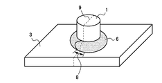
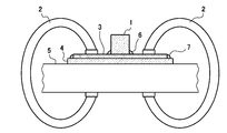
- the figure which shows typically the external appearance of the welded structure member which welded in order to evaluate molten metal embrittlement cracking property Sectional drawing which shows typically the restraint method of the test piece at the time of a welding test.
- C 0.050 to 0.150%
- C is an essential element for increasing the strength of steel sheets. If the C content is less than 0.050%, it is difficult to stably obtain a tensile strength of 780 MPa or more. When the C content exceeds 0.150%, the non-uniformity of the structure becomes remarkable, and the bending workability deteriorates. Therefore, the C content is set to 0.050 to 0.150%.
- Si 0.001 to 1.00%
- Si has the effect of suppressing the precipitation of cementite and is effective in suppressing the formation of pearlite and the like in the steel.
- the Si content needs to be 0.001% or more, and more preferably 0.005% or more.
- the Si content is set to a range of 1.00% or less.
- Mn stabilizes austenite and contributes to the formation of martensite by suppressing the formation of pearlite during cooling after heating. If the Mn content is less than 1.00%, it is difficult to ensure the amount of martensite necessary to obtain a high strength of 780 MPa or more. However, if it exceeds 2.50%, the formation of a band-like structure becomes prominent, and the bending workability deteriorates because the structure becomes non-uniform. Therefore, the Mn content is 1.00-2.50%.
- P 0.005 to 0.050% Since P is an element that deteriorates weldability and the like, it is preferable that P be less. However, excessive P removal increases the burden of the steel making process, and here, steel with a P content of 0.005 to 0.050% is targeted.
- S forms a sulfide such as MnS, and if it is present in a large amount, it becomes a factor that deteriorates the bendability.
- the S content needs to be 0.020% or less, and more preferably 0.010% or less.
- steel with an S content of 0.001 to 0.020% is targeted here.
- Al 0.005 to 0.100%
- Al is an element effective as a deoxidizer, and the content is preferably 0.005% or more. However, since a large amount of Al is a factor that degrades bendability, the Al content is set to 0.100% or less.
- Ti 0.01 to 0.10% Since Ti has a high affinity with N and fixes N in the steel as TiN, it is possible to suppress the bonding of N in the steel with B by adding Ti. Therefore, the addition of Ti is extremely effective in securing the amount of B that increases the resistance to molten metal embrittlement cracking. Ti is an element that improves the uniformity of the structure by refining the structure and contributes to the improvement of strength without deteriorating the bendability by precipitation strengthening of carbides. In order to obtain these effects sufficiently, it is necessary to add 0.01% or more of Ti. However, if added over 0.10%, the recrystallization temperature rises remarkably. Therefore, the Ti content is set to 0.01 to 0.10%.
- B 0.0005-0.0100%
- B is an element that segregates at the grain boundaries to increase the interatomic bonding force and is effective in suppressing molten metal embrittlement cracking. In order to obtain this effect, 0.0005% or more of B is necessary. However, when the B content exceeds 0.0100%, there may be a problem of deterioration in workability due to the formation of boride. Therefore, the B content is set to 0.0005 to 0.0100%.
- Nb 0 to 0.10%
- V 0 to 0.10%
- Nb and V like Ti, are elements that contribute to strength improvement without deteriorating bendability due to precipitation strengthening of carbides while improving the uniformity of the structure by refining the structure. For this reason, 1 type or 2 types of Nb and V can be added as needed. In that case, it is more effective to set the Nb content to 0.01% or more and the V content to 0.03% or more. When adding these elements, both Ti and V are preferably added in the range of 0.10% or less.
- Cr 0 to 1.00%
- Mo 0 to 1.00%
- Cr and Mo segregate at the austenite grain boundaries in the heat-affected zone during the arc welding cooling process and exhibit an action of suppressing molten metal embrittlement cracking.
- 1 type or 2 types of Cr and Mo can be added as needed. In that case, it is more effective to set the Cr content to 0.10% or more and the Mo content to 0.05% or more.
- both Cr and Mo are preferably added within a range of 1.00% or less.
- N 0.001 to 0.005% N is effective for strengthening steel, but is likely to combine with B to form BN.
- the generation of BN is not preferable because it leads to the consumption of solute B effective in improving the resistance to molten metal embrittlement cracking.
- the N content is limited to a range of 0.001 to 0.005%.
- H value C / 0.2 + Si / 5.0 + Mn / 1.3 + Cr / 1.0 + Mo / 1.2 + 0.4t ⁇ 0.7 (Cr + Mo) 1/2
- the H value defined by the above equation (1) is the “sensitivity of molten metal embrittlement cracking” using the content (mass%) of the component elements of the steel substrate and the plate thickness t (mm) of the steel substrate as parameters.
- Index A material having a large H value has a large maximum crack depth caused by molten metal embrittlement cracking.
- the H value is specified to be 2.9 or less.
- the value of the content (mass%) in steel of the element is substituted for the element symbol in the formula (1).
- Molten metal embrittlement cracking is a phenomenon in which the plated metal that is in the molten state on the surface of the base metal immediately after welding penetrates into the crystal grain boundaries of the base metal that is in the tensile stress state and causes the base metal cracking during cooling. It is. Therefore, in order to suppress weld metal embrittlement cracking, it is possible to reduce the tensile stress generated in the heat-affected zone of the base metal in the temperature range (about 400 ° C. or higher) where the plating layer is in a molten state after welding. It is valid. This tensile stress is caused by thermal shrinkage during cooling.
- the thermal contraction in the temperature range where the plated metal is melted is offset as much as possible, and thereby the plated metal is solidified. Reducing the tensile stress generated in the base metal in the meantime.
- the parameter for determining the H value includes terms for the contents of C, Si, Mn, Cr, and Mo among the constituent elements of the steel substrate. These elements have the effect of shifting the starting temperature of the martensitic transformation to the low temperature side during the cooling process of welding.
- the component element parameter of the formula (1) is intended to cause martensitic transformation to occur in the temperature range (about 400 ° C. or higher) where the plating metal is melted by adjusting the content of these elements. To do.
- the plate thickness of the steel base material greatly affects the magnitude of the tensile stress resulting from the thermal contraction of the steel base material. As the plate thickness increases, the deformation resistance increases and the tensile stress also increases. Therefore, the parameter that determines the H value includes a term that depends on the plate thickness t.
- Equation (1) is a sensitivity index equation of molten metal embrittlement cracks obtained by experiments using many steels having the above-described component ranges.
- the chemical composition was adjusted in relation to the thickness of the steel substrate so that the H value represented by the formula (1) was 2.9 or less, the molten Zn—Al—Mg system It has been found that molten metal embrittlement cracking is significantly suppressed when the plated steel sheet is arc welded.
- a DP (dual phase) steel sheet having a composite structure in which martensite or martensite and bainite are dispersed as the second phase in the main phase ferrite is used as a steel base.
- the martensite or martensite and bainite as the second phase dispersed in the main phase ferrite are 15% or more and less than 45% in total in area ratio. If the area ratio of the second phase is less than 15%, it is difficult to stably obtain a tensile strength of 780 MPa or more. On the other hand, if it is 45% or more, it becomes too hard and the workability deteriorates.
- the second phase is only martensite, but bainite may be partially dispersed.
- the ratio of the volume of bainite to the total volume of martensite and bainite is more preferably in the range of 0 to 5%. All of the examples of the present invention in the examples described later satisfy this condition.
- the bendability is improved by refining the structure.
- the average crystal grain size of the second phase is refined to 8 ⁇ m or less. It was found that bendability is ensured and useful for expanding the degree of design freedom.
- the main phase ferrite is also refined, the average crystal grain size of the second phase is particularly important for bendability. If the manufacturing conditions described later in which the average crystal grain size of the second phase is 8 ⁇ m or less are employed, the ferrite phase is sufficiently refined. For example, the average crystal grain size of the ferrite phase is 10 ⁇ m or less. In the examples described later, the average crystal grain size of the second phase is 8 ⁇ m or less, and the average crystal grain size of the ferrite phase is 10 ⁇ m or less.
- the above-mentioned hot-dip Zn-Al-Mg-based plated steel sheet is a general hot-dip galvanized steel sheet production line that sequentially applies hot rolling, pickling, cold rolling, annealing, and hot dipping processes to steel slabs. It can be manufactured using.
- the strength of steel and the resistance to molten metal embrittlement cracking can be controlled mainly by the chemical composition of the steel substrate.
- the cold rolling rate is set to 45 to 70%, and after heating to a material temperature of 740 to 860 ° C., cooling is performed at least from 740 ° C. to 650 ° C. until dipping in the plating bath. What is necessary is just to set the average cooling rate to 5 degreeC / sec or more to 5 degreeC.
- the cold rolling rate is set to 45 to 70%. If it is less than 45%, the structure after annealing becomes coarse and the bendability decreases. On the other hand, when the cold rolling rate exceeds 70%, the effect of refining the structure by cold rolling is saturated. Moreover, providing an excessively high cold rolling rate is not preferable because it increases the load of the cold rolling process.
- the plate thickness after hot rolling is adjusted in accordance with the final target plate thickness so that the cold rolling rate in this cold rolling step falls within the above range. In some cases, an intermediate cold rolling + intermediate annealing step may be inserted after the hot rolling and before this cold rolling step.
- the average cooling rate from at least 740 ° C. to 650 ° C. is set to 5 ° C./sec or more.
- the cooling rate in this temperature range is slower than this, pearlite is partially generated easily, and it becomes difficult to stably obtain a high strength of 780 MPa or more.
- This annealing is preferably performed on a continuous plating line where annealing and hot dipping can be performed with a single line passing plate.
- the annealing atmosphere is a reducing atmosphere and is managed so that the plate does not touch the atmosphere until it is immersed in the plating bath.
- the plating bath composition is, for example, mass%, Al: 3.0 to 22.0%, Mg: 0.05 to 10.0%, Ti: 0 to 0.10%, B: 0 to 0.05% , Si: 0 to 2.0%, Fe: 0 to 2.0%, and the balance is Zn and inevitable impurities.
- the plating layer composition of the obtained plated steel sheet substantially reflects the plating bath composition.
- a slab having the chemical composition shown in Table 1 is hot-rolled at a heating temperature of 1250 ° C., a finish rolling temperature of 880 ° C., and a winding temperature of 470-550 ° C. to obtain a hot-rolled steel sheet having a thickness of 2.7-5.3 mm. It was.
- the hot-rolled steel sheet After pickling the hot-rolled steel sheet, it is cold-rolled at various rolling rates to obtain a plating original sheet (steel base material) having a thickness of 2.6 mm or 1.6 mm, and this is passed through a continuous hot dipping line to produce hydrogen. -Annealed at various temperatures from 730 to 850 ° C in a nitrogen mixed gas atmosphere and cooled to about 420 ° C at various cooling rates. After that, the steel plate surface is immersed in a molten Zn—Al—Mg plating bath having the following bath composition without being exposed to the air, and then pulled up, and the amount of plating adhered to about 90 g / m 2 per side by the gas wiping method.
- a hot-dip Zn—Al—Mg plated steel sheet was produced and used as a test material.
- the plating bath temperature was about 410 ° C.
- the plating bath composition is as follows. In mass%, Al: 6%, Mg: 3%, Ti: 0.002%, B: 0.0005%, Si: 0.01%, Fe: 0.1%, balance: Zn
- annealing temperature means the heating temperature of annealing in the continuous hot dipping line
- “cooling rate after annealing” is from 740 ° C. to 650 ° C. determined from the temperature curve during cooling after annealing (heating temperature) Is less than 740 ° C., the average cooling rate is from the heating temperature to 650 ° C.).
- FIG. 1 the external appearance of the welded structural member which welded in order to evaluate molten metal embrittlement cracking property is shown typically.
- a boss (projection) 1 made of a steel bar (SS400 material defined in JIS) 20 mm in diameter and 25 mm in length is vertically placed at the center of the plate surface of a test piece 3 of 100 mm ⁇ 75 mm cut out from a test material (plated steel plate).
- the boss 1 and the test piece 3 were joined by arc welding.
- the welding wire is YGW12.
- the welding bead 6 makes one round around the boss from the welding start point.
- FIG. 2 schematically shows a method for restraining the test piece when the boss welding is performed.
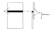
- the test piece 3 to be used for boss welding was previously attached to the central portion of the plate surface of the restraint plate 4 (SS400 material defined in JIS) having a size of 120 mm ⁇ 95 mm ⁇ 4 mm in thickness by welding all around.
- the test piece 3 was fixed together with the restraint plate 4 on the horizontal test bench 5 with the clamp 2, and the boss welding was performed in this state.
- the boss 1 / test piece 3 / constraint plate 4 joined body is cut at a cutting surface 9 passing through the central axis of the boss 1 and passing through the overlap portion 8 of the weld bead. Then, the cut surface 9 was observed with a microscope, and the maximum crack depth (maximum base material crack depth) observed in the test piece 3 was measured.
- welding was performed under extremely severe conditions in order to easily detect the occurrence of molten metal embrittlement cracking.
- a plated steel sheet (test material) having a maximum crack depth of 0.1 mm or less is judged to have a characteristic that does not cause a problem of molten metal embrittlement cracking in practice. Therefore, the case where the maximum crack depth was 0.1 mm or less was evaluated as ⁇ (molten metal embrittlement cracking resistance: good), and the others were evaluated as x (melting metal embrittlement cracking resistance: poor).
- cationic electrodeposition coating was performed under the conditions shown in Table 3.
- a sample subjected to cationic electrodeposition coating was subjected to a fatigue test under the test conditions of a stress of 50 N / mm 2 in the direction perpendicular to the welding direction and a test number of 1 ⁇ 10 5 in order to simulate fatigue due to vibration. It used for the composite corrosion test (CCT) of the conditions to show, and investigated the presence or absence of red rust generation
- FIG. 5 shows the relationship between the molten metal embrittlement cracking sensitivity index H value determined by the above equation (1) and the maximum base metal cracking depth.
- the tensile strength TS is 780 MPa or more
- the limit bending R is 2 mm or less
- the maximum base metal cracking depth is 0.1 mm or less
- the corrosion resistance of the welded part is also evaluated as ⁇ . That is, a plated steel sheet excellent in strength, bendability, molten metal embrittlement cracking resistance, and corrosion resistance of the welded portion could be realized.
- No. 23 has a low amount of Ti because of a large amount of Ti
- No. 24 has a low amount of C, so that sufficient strength cannot be obtained.
- .26 has a low B content
- the maximum base metal crack depth is large
- Nos. 27 and 28 have a high H value
- No. 29 has a high C content and a high H value, so the bendability is poor and the maximum base metal crack depth is large.
- No. 30 has a high H value
- the maximum base metal crack depth is large
- No. 31 has a high Mn amount and an H value, so that the bendability is poor and the maximum base material crack depth is large. Since Nos.
- No. 34 has a low rolling ratio in cold rolling, so that the crystal grain size of the second phase is not sufficiently refined and the bendability is poor.
- No. 35 has poor bendability due to its low annealing temperature in the continuous hot dipping line.
- No. 36 has a low cooling rate after annealing in the continuous hot dipping line, so the crystal grain size of the second phase is not sufficiently refined and the bendability is poor.
Landscapes
- Chemical & Material Sciences (AREA)
- Engineering & Computer Science (AREA)
- Organic Chemistry (AREA)
- Materials Engineering (AREA)
- Mechanical Engineering (AREA)
- Metallurgy (AREA)
- Physics & Mathematics (AREA)
- Thermal Sciences (AREA)
- Crystallography & Structural Chemistry (AREA)
- Chemical Kinetics & Catalysis (AREA)
- Heat Treatment Of Sheet Steel (AREA)
- Coating With Molten Metal (AREA)
- Oil, Petroleum & Natural Gas (AREA)
Abstract
Priority Applications (7)
| Application Number | Priority Date | Filing Date | Title |
|---|---|---|---|
| MX2015013538A MX2015013538A (es) | 2013-03-26 | 2014-03-13 | Placa de acero chapada de alta resistencia para elemento estructural soldado, metodo para producir la misma. |
| CA2905623A CA2905623A1 (fr) | 2013-03-26 | 2014-03-13 | Feuille d'acier plaquee a resistance elevee pour un element structural soude et procede de fabrication de ladite feuille |
| KR1020157030683A KR102210135B1 (ko) | 2013-03-26 | 2014-03-13 | 용접 구조 부재용 고강도 도금 강판 및 이의 제조법 |
| CN201480018099.6A CN105121681B (zh) | 2013-03-26 | 2014-03-13 | 焊接构造部件用高强度镀敷钢板及其制造方法 |
| US14/775,733 US10100395B2 (en) | 2013-03-26 | 2014-03-13 | High-strength plated steel plate for welded structural member, and method for producing the same |
| EP14773567.4A EP2980237A4 (fr) | 2013-03-26 | 2014-03-13 | Feuille d'acier plaquée à résistance élevée pour un élément structural soudé et procédé de fabrication de ladite feuille |
| US16/132,602 US20190010596A1 (en) | 2013-03-26 | 2018-09-17 | High-strength plated steel plate for welded structural member, and method for producing the same |
Applications Claiming Priority (2)
| Application Number | Priority Date | Filing Date | Title |
|---|---|---|---|
| JP2013-064370 | 2013-03-26 | ||
| JP2013064370A JP6049516B2 (ja) | 2013-03-26 | 2013-03-26 | 溶接構造部材用高強度めっき鋼板およびその製造法 |
Related Child Applications (2)
| Application Number | Title | Priority Date | Filing Date |
|---|---|---|---|
| US14/775,733 A-371-Of-International US10100395B2 (en) | 2013-03-26 | 2014-03-13 | High-strength plated steel plate for welded structural member, and method for producing the same |
| US16/132,602 Division US20190010596A1 (en) | 2013-03-26 | 2018-09-17 | High-strength plated steel plate for welded structural member, and method for producing the same |
Publications (1)
| Publication Number | Publication Date |
|---|---|
| WO2014156671A1 true WO2014156671A1 (fr) | 2014-10-02 |
Family
ID=51623654
Family Applications (1)
| Application Number | Title | Priority Date | Filing Date |
|---|---|---|---|
| PCT/JP2014/056620 WO2014156671A1 (fr) | 2013-03-26 | 2014-03-13 | Feuille d'acier plaquée à résistance élevée pour un élément structural soudé et procédé de fabrication de ladite feuille |
Country Status (10)
| Country | Link |
|---|---|
| US (2) | US10100395B2 (fr) |
| EP (1) | EP2980237A4 (fr) |
| JP (1) | JP6049516B2 (fr) |
| KR (1) | KR102210135B1 (fr) |
| CN (1) | CN105121681B (fr) |
| CA (1) | CA2905623A1 (fr) |
| MX (1) | MX2015013538A (fr) |
| MY (1) | MY171301A (fr) |
| TW (1) | TWI618816B (fr) |
| WO (1) | WO2014156671A1 (fr) |
Families Citing this family (12)
| Publication number | Priority date | Publication date | Assignee | Title |
|---|---|---|---|---|
| JP2017115205A (ja) * | 2015-12-24 | 2017-06-29 | 日新製鋼株式会社 | めっき密着性に優れた溶融Zn−Al−Mg合金めっき鋼板の製造方法 |
| JP2017145441A (ja) * | 2016-02-16 | 2017-08-24 | 日新製鋼株式会社 | 黒色表面被覆高強度鋼板およびその製造方法 |
| US10961600B2 (en) | 2016-03-31 | 2021-03-30 | Jfe Steel Corporation | Steel sheet and plated steel sheet, method for producing steel sheet, and method for producing plated steel sheet |
| KR101858853B1 (ko) | 2016-12-19 | 2018-06-28 | 주식회사 포스코 | 용접성이 우수한 전봉강관용 열연강판 및 이의 제조방법 |
| JP6816550B2 (ja) * | 2017-02-17 | 2021-01-20 | 日本製鉄株式会社 | 曲げ加工性に優れた黒色表面被覆高強度溶融Zn−Al−Mg系めっき鋼板及びその製造方法 |
| JP6809648B1 (ja) * | 2019-01-29 | 2021-01-06 | Jfeスチール株式会社 | 高強度鋼板及びその製造方法 |
| JP7288184B2 (ja) * | 2019-03-22 | 2023-06-07 | 日本製鉄株式会社 | 溶融Zn-Al-Mg系めっき鋼板の製造方法 |
| JP7059979B2 (ja) * | 2019-04-25 | 2022-04-26 | Jfeスチール株式会社 | スポット溶接部材 |
| JP2021042419A (ja) * | 2019-09-10 | 2021-03-18 | 日本電産株式会社 | 亜鉛合金及びその製造方法 |
| JP7241889B2 (ja) * | 2020-02-13 | 2023-03-17 | 日本製鉄株式会社 | 接合部品及びその製造方法 |
| KR102451005B1 (ko) * | 2020-10-23 | 2022-10-07 | 주식회사 포스코 | 열적 안정성이 우수한 고강도 강판 및 이의 제조방법 |
| CN113388796B (zh) * | 2021-08-16 | 2021-11-02 | 天津市新宇彩板有限公司 | 钢材表面热镀锌铝镁镀液及使用该镀液的镀覆方法 |
Citations (11)
| Publication number | Priority date | Publication date | Assignee | Title |
|---|---|---|---|---|
| JP2004315848A (ja) * | 2003-02-27 | 2004-11-11 | Nisshin Steel Co Ltd | 溶融金属脆化による溶接加工割れのないZn−Al−Mg系溶融めっき鋼板 |
| JP2006307260A (ja) * | 2005-04-27 | 2006-11-09 | Toyo Kohan Co Ltd | プラズマディスプレイ固定板用鋼板、プラズマディスプレイ固定用鋼板の製造方法及びプラズマディスプレイ固定板 |
| JP2007092126A (ja) * | 2005-09-29 | 2007-04-12 | Jfe Steel Kk | 曲げ剛性に優れた高強度薄鋼板およびその製造方法 |
| JP2007231369A (ja) | 2006-03-01 | 2007-09-13 | Nippon Steel Corp | 成形性と溶接性に優れた高強度冷延鋼板、高強度溶融亜鉛めっき鋼板及び高強度合金化溶融亜鉛めっき鋼板、並びに、高強度冷延鋼板の製造方法、高強度溶融亜鉛めっき鋼板の製造方法、高強度合金化溶融亜鉛めっき鋼板の製造方法 |
| JP2007277729A (ja) * | 2007-06-11 | 2007-10-25 | Jfe Steel Kk | 高強度溶融亜鉛メッキ鋼板およびその製造方法 |
| JP2009172679A (ja) * | 2007-12-27 | 2009-08-06 | Nippon Steel Corp | 亜鉛めっき鋼板溶接用ステンレス鋼フラックス入り溶接ワイヤおよびこれを用いた亜鉛めっき鋼板のアーク溶接方法 |
| JP2009179852A (ja) * | 2008-01-31 | 2009-08-13 | Jfe Steel Corp | 成形性に優れた高強度溶融亜鉛めっき鋼板およびその製造方法 |
| JP2009228079A (ja) | 2008-03-24 | 2009-10-08 | Nisshin Steel Co Ltd | 耐溶融金属脆化割れ性に優れたZn−Al−Mg系めっき鋼板およびその製造方法 |
| JP2009249733A (ja) * | 2008-04-10 | 2009-10-29 | Nippon Steel Corp | 時効性劣化が極めて少なく優れた焼付け硬化性を有する高強度鋼板とその製造方法 |
| JP2011132602A (ja) * | 2009-11-30 | 2011-07-07 | Nippon Steel Corp | 高強度冷延鋼板、高強度溶融亜鉛めっき鋼板および高強度合金化溶融亜鉛めっき鋼板 |
| JP2012193452A (ja) * | 2011-02-28 | 2012-10-11 | Nisshin Steel Co Ltd | 溶融Zn−Al−Mg系めっき鋼板および製造方法 |
Family Cites Families (7)
| Publication number | Priority date | Publication date | Assignee | Title |
|---|---|---|---|---|
| JP4085583B2 (ja) * | 2001-02-27 | 2008-05-14 | Jfeスチール株式会社 | 高強度冷延溶融亜鉛メッキ鋼板およびその製造方法 |
| US6677058B1 (en) * | 2002-07-31 | 2004-01-13 | Nisshin Steel Co., Ltd. | Hot-dip Zn plated steel sheet excellent in luster-retaining property and method of producing the same |
| JP5082432B2 (ja) * | 2006-12-26 | 2012-11-28 | Jfeスチール株式会社 | 高強度溶融亜鉛めっき鋼板の製造方法 |
| CN102369303A (zh) * | 2009-03-10 | 2012-03-07 | 日新制钢株式会社 | 耐熔融金属脆化裂纹性优异的锌系合金镀敷钢材 |
| JP2010235989A (ja) * | 2009-03-30 | 2010-10-21 | Nisshin Steel Co Ltd | 耐溶融金属脆化特性に優れた高強度Zn−Al−Mg系めっき鋼板およびその製造方法 |
| JP5641741B2 (ja) * | 2010-01-28 | 2014-12-17 | 日新製鋼株式会社 | 曲げ性および耐溶融金属脆化特性に優れた高強度Zn−Al−Mg系めっき鋼板 |
| ES2765674T3 (es) * | 2010-08-23 | 2020-06-10 | Nippon Steel Corp | Lámina de acero laminado en frío y procedimiento para la producción de la misma |
-
2013
- 2013-03-26 JP JP2013064370A patent/JP6049516B2/ja active Active
-
2014
- 2014-03-13 CA CA2905623A patent/CA2905623A1/fr not_active Abandoned
- 2014-03-13 CN CN201480018099.6A patent/CN105121681B/zh active Active
- 2014-03-13 MY MYPI2015703365A patent/MY171301A/en unknown
- 2014-03-13 MX MX2015013538A patent/MX2015013538A/es unknown
- 2014-03-13 EP EP14773567.4A patent/EP2980237A4/fr not_active Withdrawn
- 2014-03-13 WO PCT/JP2014/056620 patent/WO2014156671A1/fr active Application Filing
- 2014-03-13 US US14/775,733 patent/US10100395B2/en active Active
- 2014-03-13 KR KR1020157030683A patent/KR102210135B1/ko active IP Right Grant
- 2014-03-25 TW TW103110993A patent/TWI618816B/zh active
-
2018
- 2018-09-17 US US16/132,602 patent/US20190010596A1/en not_active Abandoned
Patent Citations (11)
| Publication number | Priority date | Publication date | Assignee | Title |
|---|---|---|---|---|
| JP2004315848A (ja) * | 2003-02-27 | 2004-11-11 | Nisshin Steel Co Ltd | 溶融金属脆化による溶接加工割れのないZn−Al−Mg系溶融めっき鋼板 |
| JP2006307260A (ja) * | 2005-04-27 | 2006-11-09 | Toyo Kohan Co Ltd | プラズマディスプレイ固定板用鋼板、プラズマディスプレイ固定用鋼板の製造方法及びプラズマディスプレイ固定板 |
| JP2007092126A (ja) * | 2005-09-29 | 2007-04-12 | Jfe Steel Kk | 曲げ剛性に優れた高強度薄鋼板およびその製造方法 |
| JP2007231369A (ja) | 2006-03-01 | 2007-09-13 | Nippon Steel Corp | 成形性と溶接性に優れた高強度冷延鋼板、高強度溶融亜鉛めっき鋼板及び高強度合金化溶融亜鉛めっき鋼板、並びに、高強度冷延鋼板の製造方法、高強度溶融亜鉛めっき鋼板の製造方法、高強度合金化溶融亜鉛めっき鋼板の製造方法 |
| JP2007277729A (ja) * | 2007-06-11 | 2007-10-25 | Jfe Steel Kk | 高強度溶融亜鉛メッキ鋼板およびその製造方法 |
| JP2009172679A (ja) * | 2007-12-27 | 2009-08-06 | Nippon Steel Corp | 亜鉛めっき鋼板溶接用ステンレス鋼フラックス入り溶接ワイヤおよびこれを用いた亜鉛めっき鋼板のアーク溶接方法 |
| JP2009179852A (ja) * | 2008-01-31 | 2009-08-13 | Jfe Steel Corp | 成形性に優れた高強度溶融亜鉛めっき鋼板およびその製造方法 |
| JP2009228079A (ja) | 2008-03-24 | 2009-10-08 | Nisshin Steel Co Ltd | 耐溶融金属脆化割れ性に優れたZn−Al−Mg系めっき鋼板およびその製造方法 |
| JP2009249733A (ja) * | 2008-04-10 | 2009-10-29 | Nippon Steel Corp | 時効性劣化が極めて少なく優れた焼付け硬化性を有する高強度鋼板とその製造方法 |
| JP2011132602A (ja) * | 2009-11-30 | 2011-07-07 | Nippon Steel Corp | 高強度冷延鋼板、高強度溶融亜鉛めっき鋼板および高強度合金化溶融亜鉛めっき鋼板 |
| JP2012193452A (ja) * | 2011-02-28 | 2012-10-11 | Nisshin Steel Co Ltd | 溶融Zn−Al−Mg系めっき鋼板および製造方法 |
Also Published As
| Publication number | Publication date |
|---|---|
| US10100395B2 (en) | 2018-10-16 |
| CA2905623A1 (fr) | 2014-10-02 |
| US20190010596A1 (en) | 2019-01-10 |
| JP2014189812A (ja) | 2014-10-06 |
| MY171301A (en) | 2019-10-08 |
| EP2980237A1 (fr) | 2016-02-03 |
| JP6049516B2 (ja) | 2016-12-21 |
| US20160032438A1 (en) | 2016-02-04 |
| TWI618816B (zh) | 2018-03-21 |
| KR102210135B1 (ko) | 2021-02-01 |
| MX2015013538A (es) | 2016-02-05 |
| CN105121681B (zh) | 2017-04-26 |
| EP2980237A4 (fr) | 2016-11-30 |
| KR20150133838A (ko) | 2015-11-30 |
| TW201443280A (zh) | 2014-11-16 |
| CN105121681A (zh) | 2015-12-02 |
Similar Documents
| Publication | Publication Date | Title |
|---|---|---|
| JP6049516B2 (ja) | 溶接構造部材用高強度めっき鋼板およびその製造法 | |
| JP5858199B2 (ja) | 高強度溶融亜鉛めっき鋼板及びその製造方法 | |
| JP6323627B1 (ja) | 高強度冷延薄鋼板及びその製造方法 | |
| JP6525114B1 (ja) | 高強度亜鉛めっき鋼板およびその製造方法 | |
| JP5858032B2 (ja) | 高強度鋼板およびその製造方法 | |
| JP5936390B2 (ja) | 溶融Zn−Al−Mg系めっき鋼板および製造方法 | |
| JP6777173B2 (ja) | スポット溶接用高強度亜鉛めっき鋼板 | |
| WO2019189842A1 (fr) | Tôle d'acier galvanisée à résistance élevée, élément à résistance élevée et leurs procédés de fabrication | |
| JP5704721B2 (ja) | シーム溶接性に優れた高強度鋼板 | |
| WO2016199922A1 (fr) | Tôle d'acier recuite par galvanisation et procédé permettant de fabriquer cette dernière | |
| WO2018030500A1 (fr) | Tôle d'acier mince à haute résistance et son procédé de fabrication | |
| JP5641741B2 (ja) | 曲げ性および耐溶融金属脆化特性に優れた高強度Zn−Al−Mg系めっき鋼板 | |
| CA2786381C (fr) | Tole d'acier gavalnisee a haute resistance presentant une excellente formabilite et une aptitude au soudage par points et methode de fabrication connexe | |
| JP6201571B2 (ja) | 穴拡げ性と伸びと溶接特性に優れた高強度熱延鋼板及びその製造方法 | |
| WO2018062342A1 (fr) | Tôle en acier plaquée hautement résistante, et procédé de fabrication de celle-ci | |
| JP6950826B2 (ja) | 高強度鋼板、熱延鋼板の製造方法、冷延フルハード鋼板の製造方法および高強度鋼板の製造方法 | |
| JP5264234B2 (ja) | 耐溶融金属脆化割れ性に優れたZn−Al−Mg系めっき鋼板およびその製造方法 | |
| JP2010235989A (ja) | 耐溶融金属脆化特性に優れた高強度Zn−Al−Mg系めっき鋼板およびその製造方法 | |
| JP5860500B2 (ja) | 耐溶融金属脆化特性に優れた高強度Zn−Al−Mg系めっき鋼板およびその製造方法 |
Legal Events
| Date | Code | Title | Description |
|---|---|---|---|
| 121 | Ep: the epo has been informed by wipo that ep was designated in this application |
Ref document number: 14773567 Country of ref document: EP Kind code of ref document: A1 |
|
| ENP | Entry into the national phase |
Ref document number: 2905623 Country of ref document: CA |
|
| WWE | Wipo information: entry into national phase |
Ref document number: 14775733 Country of ref document: US |
|
| WWE | Wipo information: entry into national phase |
Ref document number: 2014773567 Country of ref document: EP Ref document number: MX/A/2015/013538 Country of ref document: MX |
|
| NENP | Non-entry into the national phase |
Ref country code: DE |
|
| WWE | Wipo information: entry into national phase |
Ref document number: IDP00201506834 Country of ref document: ID |
|
| ENP | Entry into the national phase |
Ref document number: 20157030683 Country of ref document: KR Kind code of ref document: A |