WO2019189842A1 - Tôle d'acier galvanisée à résistance élevée, élément à résistance élevée et leurs procédés de fabrication - Google Patents
Tôle d'acier galvanisée à résistance élevée, élément à résistance élevée et leurs procédés de fabrication Download PDFInfo
- Publication number
- WO2019189842A1 WO2019189842A1 PCT/JP2019/014221 JP2019014221W WO2019189842A1 WO 2019189842 A1 WO2019189842 A1 WO 2019189842A1 JP 2019014221 W JP2019014221 W JP 2019014221W WO 2019189842 A1 WO2019189842 A1 WO 2019189842A1
- Authority
- WO
- WIPO (PCT)
- Prior art keywords
- less
- steel sheet
- strength
- galvanized steel
- temperature
- Prior art date
Links
Images
Classifications
-
- C—CHEMISTRY; METALLURGY
- C22—METALLURGY; FERROUS OR NON-FERROUS ALLOYS; TREATMENT OF ALLOYS OR NON-FERROUS METALS
- C22C—ALLOYS
- C22C38/00—Ferrous alloys, e.g. steel alloys
- C22C38/02—Ferrous alloys, e.g. steel alloys containing silicon
-
- C—CHEMISTRY; METALLURGY
- C23—COATING METALLIC MATERIAL; COATING MATERIAL WITH METALLIC MATERIAL; CHEMICAL SURFACE TREATMENT; DIFFUSION TREATMENT OF METALLIC MATERIAL; COATING BY VACUUM EVAPORATION, BY SPUTTERING, BY ION IMPLANTATION OR BY CHEMICAL VAPOUR DEPOSITION, IN GENERAL; INHIBITING CORROSION OF METALLIC MATERIAL OR INCRUSTATION IN GENERAL
- C23G—CLEANING OR DE-GREASING OF METALLIC MATERIAL BY CHEMICAL METHODS OTHER THAN ELECTROLYSIS
- C23G1/00—Cleaning or pickling metallic material with solutions or molten salts
- C23G1/02—Cleaning or pickling metallic material with solutions or molten salts with acid solutions
- C23G1/08—Iron or steel
-
- C—CHEMISTRY; METALLURGY
- C21—METALLURGY OF IRON
- C21D—MODIFYING THE PHYSICAL STRUCTURE OF FERROUS METALS; GENERAL DEVICES FOR HEAT TREATMENT OF FERROUS OR NON-FERROUS METALS OR ALLOYS; MAKING METAL MALLEABLE, e.g. BY DECARBURISATION OR TEMPERING
- C21D1/00—General methods or devices for heat treatment, e.g. annealing, hardening, quenching or tempering
- C21D1/18—Hardening; Quenching with or without subsequent tempering
- C21D1/19—Hardening; Quenching with or without subsequent tempering by interrupted quenching
- C21D1/20—Isothermal quenching, e.g. bainitic hardening
-
- C—CHEMISTRY; METALLURGY
- C21—METALLURGY OF IRON
- C21D—MODIFYING THE PHYSICAL STRUCTURE OF FERROUS METALS; GENERAL DEVICES FOR HEAT TREATMENT OF FERROUS OR NON-FERROUS METALS OR ALLOYS; MAKING METAL MALLEABLE, e.g. BY DECARBURISATION OR TEMPERING
- C21D1/00—General methods or devices for heat treatment, e.g. annealing, hardening, quenching or tempering
- C21D1/26—Methods of annealing
-
- C—CHEMISTRY; METALLURGY
- C21—METALLURGY OF IRON
- C21D—MODIFYING THE PHYSICAL STRUCTURE OF FERROUS METALS; GENERAL DEVICES FOR HEAT TREATMENT OF FERROUS OR NON-FERROUS METALS OR ALLOYS; MAKING METAL MALLEABLE, e.g. BY DECARBURISATION OR TEMPERING
- C21D1/00—General methods or devices for heat treatment, e.g. annealing, hardening, quenching or tempering
- C21D1/74—Methods of treatment in inert gas, controlled atmosphere, vacuum or pulverulent material
- C21D1/76—Adjusting the composition of the atmosphere
-
- C—CHEMISTRY; METALLURGY
- C21—METALLURGY OF IRON
- C21D—MODIFYING THE PHYSICAL STRUCTURE OF FERROUS METALS; GENERAL DEVICES FOR HEAT TREATMENT OF FERROUS OR NON-FERROUS METALS OR ALLOYS; MAKING METAL MALLEABLE, e.g. BY DECARBURISATION OR TEMPERING
- C21D6/00—Heat treatment of ferrous alloys
- C21D6/005—Heat treatment of ferrous alloys containing Mn
-
- C—CHEMISTRY; METALLURGY
- C21—METALLURGY OF IRON
- C21D—MODIFYING THE PHYSICAL STRUCTURE OF FERROUS METALS; GENERAL DEVICES FOR HEAT TREATMENT OF FERROUS OR NON-FERROUS METALS OR ALLOYS; MAKING METAL MALLEABLE, e.g. BY DECARBURISATION OR TEMPERING
- C21D8/00—Modifying the physical properties by deformation combined with, or followed by, heat treatment
- C21D8/02—Modifying the physical properties by deformation combined with, or followed by, heat treatment during manufacturing of plates or strips
- C21D8/0205—Modifying the physical properties by deformation combined with, or followed by, heat treatment during manufacturing of plates or strips of ferrous alloys
-
- C—CHEMISTRY; METALLURGY
- C21—METALLURGY OF IRON
- C21D—MODIFYING THE PHYSICAL STRUCTURE OF FERROUS METALS; GENERAL DEVICES FOR HEAT TREATMENT OF FERROUS OR NON-FERROUS METALS OR ALLOYS; MAKING METAL MALLEABLE, e.g. BY DECARBURISATION OR TEMPERING
- C21D8/00—Modifying the physical properties by deformation combined with, or followed by, heat treatment
- C21D8/02—Modifying the physical properties by deformation combined with, or followed by, heat treatment during manufacturing of plates or strips
- C21D8/0221—Modifying the physical properties by deformation combined with, or followed by, heat treatment during manufacturing of plates or strips characterised by the working steps
- C21D8/0226—Hot rolling
-
- C—CHEMISTRY; METALLURGY
- C21—METALLURGY OF IRON
- C21D—MODIFYING THE PHYSICAL STRUCTURE OF FERROUS METALS; GENERAL DEVICES FOR HEAT TREATMENT OF FERROUS OR NON-FERROUS METALS OR ALLOYS; MAKING METAL MALLEABLE, e.g. BY DECARBURISATION OR TEMPERING
- C21D8/00—Modifying the physical properties by deformation combined with, or followed by, heat treatment
- C21D8/02—Modifying the physical properties by deformation combined with, or followed by, heat treatment during manufacturing of plates or strips
- C21D8/0221—Modifying the physical properties by deformation combined with, or followed by, heat treatment during manufacturing of plates or strips characterised by the working steps
- C21D8/0236—Cold rolling
-
- C—CHEMISTRY; METALLURGY
- C21—METALLURGY OF IRON
- C21D—MODIFYING THE PHYSICAL STRUCTURE OF FERROUS METALS; GENERAL DEVICES FOR HEAT TREATMENT OF FERROUS OR NON-FERROUS METALS OR ALLOYS; MAKING METAL MALLEABLE, e.g. BY DECARBURISATION OR TEMPERING
- C21D8/00—Modifying the physical properties by deformation combined with, or followed by, heat treatment
- C21D8/02—Modifying the physical properties by deformation combined with, or followed by, heat treatment during manufacturing of plates or strips
- C21D8/0247—Modifying the physical properties by deformation combined with, or followed by, heat treatment during manufacturing of plates or strips characterised by the heat treatment
-
- C—CHEMISTRY; METALLURGY
- C21—METALLURGY OF IRON
- C21D—MODIFYING THE PHYSICAL STRUCTURE OF FERROUS METALS; GENERAL DEVICES FOR HEAT TREATMENT OF FERROUS OR NON-FERROUS METALS OR ALLOYS; MAKING METAL MALLEABLE, e.g. BY DECARBURISATION OR TEMPERING
- C21D8/00—Modifying the physical properties by deformation combined with, or followed by, heat treatment
- C21D8/02—Modifying the physical properties by deformation combined with, or followed by, heat treatment during manufacturing of plates or strips
- C21D8/0278—Modifying the physical properties by deformation combined with, or followed by, heat treatment during manufacturing of plates or strips involving a particular surface treatment
-
- C—CHEMISTRY; METALLURGY
- C21—METALLURGY OF IRON
- C21D—MODIFYING THE PHYSICAL STRUCTURE OF FERROUS METALS; GENERAL DEVICES FOR HEAT TREATMENT OF FERROUS OR NON-FERROUS METALS OR ALLOYS; MAKING METAL MALLEABLE, e.g. BY DECARBURISATION OR TEMPERING
- C21D8/00—Modifying the physical properties by deformation combined with, or followed by, heat treatment
- C21D8/02—Modifying the physical properties by deformation combined with, or followed by, heat treatment during manufacturing of plates or strips
- C21D8/04—Modifying the physical properties by deformation combined with, or followed by, heat treatment during manufacturing of plates or strips to produce plates or strips for deep-drawing
- C21D8/0405—Modifying the physical properties by deformation combined with, or followed by, heat treatment during manufacturing of plates or strips to produce plates or strips for deep-drawing of ferrous alloys
-
- C—CHEMISTRY; METALLURGY
- C21—METALLURGY OF IRON
- C21D—MODIFYING THE PHYSICAL STRUCTURE OF FERROUS METALS; GENERAL DEVICES FOR HEAT TREATMENT OF FERROUS OR NON-FERROUS METALS OR ALLOYS; MAKING METAL MALLEABLE, e.g. BY DECARBURISATION OR TEMPERING
- C21D8/00—Modifying the physical properties by deformation combined with, or followed by, heat treatment
- C21D8/02—Modifying the physical properties by deformation combined with, or followed by, heat treatment during manufacturing of plates or strips
- C21D8/04—Modifying the physical properties by deformation combined with, or followed by, heat treatment during manufacturing of plates or strips to produce plates or strips for deep-drawing
- C21D8/0421—Modifying the physical properties by deformation combined with, or followed by, heat treatment during manufacturing of plates or strips to produce plates or strips for deep-drawing characterised by the working steps
- C21D8/0436—Cold rolling
-
- C—CHEMISTRY; METALLURGY
- C21—METALLURGY OF IRON
- C21D—MODIFYING THE PHYSICAL STRUCTURE OF FERROUS METALS; GENERAL DEVICES FOR HEAT TREATMENT OF FERROUS OR NON-FERROUS METALS OR ALLOYS; MAKING METAL MALLEABLE, e.g. BY DECARBURISATION OR TEMPERING
- C21D8/00—Modifying the physical properties by deformation combined with, or followed by, heat treatment
- C21D8/02—Modifying the physical properties by deformation combined with, or followed by, heat treatment during manufacturing of plates or strips
- C21D8/04—Modifying the physical properties by deformation combined with, or followed by, heat treatment during manufacturing of plates or strips to produce plates or strips for deep-drawing
- C21D8/0447—Modifying the physical properties by deformation combined with, or followed by, heat treatment during manufacturing of plates or strips to produce plates or strips for deep-drawing characterised by the heat treatment
-
- C—CHEMISTRY; METALLURGY
- C21—METALLURGY OF IRON
- C21D—MODIFYING THE PHYSICAL STRUCTURE OF FERROUS METALS; GENERAL DEVICES FOR HEAT TREATMENT OF FERROUS OR NON-FERROUS METALS OR ALLOYS; MAKING METAL MALLEABLE, e.g. BY DECARBURISATION OR TEMPERING
- C21D9/00—Heat treatment, e.g. annealing, hardening, quenching or tempering, adapted for particular articles; Furnaces therefor
- C21D9/46—Heat treatment, e.g. annealing, hardening, quenching or tempering, adapted for particular articles; Furnaces therefor for sheet metals
- C21D9/48—Heat treatment, e.g. annealing, hardening, quenching or tempering, adapted for particular articles; Furnaces therefor for sheet metals deep-drawing sheets
-
- C—CHEMISTRY; METALLURGY
- C22—METALLURGY; FERROUS OR NON-FERROUS ALLOYS; TREATMENT OF ALLOYS OR NON-FERROUS METALS
- C22C—ALLOYS
- C22C18/00—Alloys based on zinc
-
- C—CHEMISTRY; METALLURGY
- C22—METALLURGY; FERROUS OR NON-FERROUS ALLOYS; TREATMENT OF ALLOYS OR NON-FERROUS METALS
- C22C—ALLOYS
- C22C18/00—Alloys based on zinc
- C22C18/04—Alloys based on zinc with aluminium as the next major constituent
-
- C—CHEMISTRY; METALLURGY
- C22—METALLURGY; FERROUS OR NON-FERROUS ALLOYS; TREATMENT OF ALLOYS OR NON-FERROUS METALS
- C22C—ALLOYS
- C22C38/00—Ferrous alloys, e.g. steel alloys
-
- C—CHEMISTRY; METALLURGY
- C22—METALLURGY; FERROUS OR NON-FERROUS ALLOYS; TREATMENT OF ALLOYS OR NON-FERROUS METALS
- C22C—ALLOYS
- C22C38/00—Ferrous alloys, e.g. steel alloys
- C22C38/001—Ferrous alloys, e.g. steel alloys containing N
-
- C—CHEMISTRY; METALLURGY
- C22—METALLURGY; FERROUS OR NON-FERROUS ALLOYS; TREATMENT OF ALLOYS OR NON-FERROUS METALS
- C22C—ALLOYS
- C22C38/00—Ferrous alloys, e.g. steel alloys
- C22C38/002—Ferrous alloys, e.g. steel alloys containing In, Mg, or other elements not provided for in one single group C22C38/001 - C22C38/60
-
- C—CHEMISTRY; METALLURGY
- C22—METALLURGY; FERROUS OR NON-FERROUS ALLOYS; TREATMENT OF ALLOYS OR NON-FERROUS METALS
- C22C—ALLOYS
- C22C38/00—Ferrous alloys, e.g. steel alloys
- C22C38/008—Ferrous alloys, e.g. steel alloys containing tin
-
- C—CHEMISTRY; METALLURGY
- C22—METALLURGY; FERROUS OR NON-FERROUS ALLOYS; TREATMENT OF ALLOYS OR NON-FERROUS METALS
- C22C—ALLOYS
- C22C38/00—Ferrous alloys, e.g. steel alloys
- C22C38/04—Ferrous alloys, e.g. steel alloys containing manganese
-
- C—CHEMISTRY; METALLURGY
- C22—METALLURGY; FERROUS OR NON-FERROUS ALLOYS; TREATMENT OF ALLOYS OR NON-FERROUS METALS
- C22C—ALLOYS
- C22C38/00—Ferrous alloys, e.g. steel alloys
- C22C38/06—Ferrous alloys, e.g. steel alloys containing aluminium
-
- C—CHEMISTRY; METALLURGY
- C22—METALLURGY; FERROUS OR NON-FERROUS ALLOYS; TREATMENT OF ALLOYS OR NON-FERROUS METALS
- C22C—ALLOYS
- C22C38/00—Ferrous alloys, e.g. steel alloys
- C22C38/12—Ferrous alloys, e.g. steel alloys containing tungsten, tantalum, molybdenum, vanadium, or niobium
-
- C—CHEMISTRY; METALLURGY
- C22—METALLURGY; FERROUS OR NON-FERROUS ALLOYS; TREATMENT OF ALLOYS OR NON-FERROUS METALS
- C22C—ALLOYS
- C22C38/00—Ferrous alloys, e.g. steel alloys
- C22C38/14—Ferrous alloys, e.g. steel alloys containing titanium or zirconium
-
- C—CHEMISTRY; METALLURGY
- C22—METALLURGY; FERROUS OR NON-FERROUS ALLOYS; TREATMENT OF ALLOYS OR NON-FERROUS METALS
- C22C—ALLOYS
- C22C38/00—Ferrous alloys, e.g. steel alloys
- C22C38/16—Ferrous alloys, e.g. steel alloys containing copper
-
- C—CHEMISTRY; METALLURGY
- C22—METALLURGY; FERROUS OR NON-FERROUS ALLOYS; TREATMENT OF ALLOYS OR NON-FERROUS METALS
- C22C—ALLOYS
- C22C38/00—Ferrous alloys, e.g. steel alloys
- C22C38/18—Ferrous alloys, e.g. steel alloys containing chromium
- C22C38/20—Ferrous alloys, e.g. steel alloys containing chromium with copper
-
- C—CHEMISTRY; METALLURGY
- C22—METALLURGY; FERROUS OR NON-FERROUS ALLOYS; TREATMENT OF ALLOYS OR NON-FERROUS METALS
- C22C—ALLOYS
- C22C38/00—Ferrous alloys, e.g. steel alloys
- C22C38/18—Ferrous alloys, e.g. steel alloys containing chromium
- C22C38/22—Ferrous alloys, e.g. steel alloys containing chromium with molybdenum or tungsten
-
- C—CHEMISTRY; METALLURGY
- C22—METALLURGY; FERROUS OR NON-FERROUS ALLOYS; TREATMENT OF ALLOYS OR NON-FERROUS METALS
- C22C—ALLOYS
- C22C38/00—Ferrous alloys, e.g. steel alloys
- C22C38/18—Ferrous alloys, e.g. steel alloys containing chromium
- C22C38/24—Ferrous alloys, e.g. steel alloys containing chromium with vanadium
-
- C—CHEMISTRY; METALLURGY
- C22—METALLURGY; FERROUS OR NON-FERROUS ALLOYS; TREATMENT OF ALLOYS OR NON-FERROUS METALS
- C22C—ALLOYS
- C22C38/00—Ferrous alloys, e.g. steel alloys
- C22C38/18—Ferrous alloys, e.g. steel alloys containing chromium
- C22C38/26—Ferrous alloys, e.g. steel alloys containing chromium with niobium or tantalum
-
- C—CHEMISTRY; METALLURGY
- C22—METALLURGY; FERROUS OR NON-FERROUS ALLOYS; TREATMENT OF ALLOYS OR NON-FERROUS METALS
- C22C—ALLOYS
- C22C38/00—Ferrous alloys, e.g. steel alloys
- C22C38/18—Ferrous alloys, e.g. steel alloys containing chromium
- C22C38/28—Ferrous alloys, e.g. steel alloys containing chromium with titanium or zirconium
-
- C—CHEMISTRY; METALLURGY
- C22—METALLURGY; FERROUS OR NON-FERROUS ALLOYS; TREATMENT OF ALLOYS OR NON-FERROUS METALS
- C22C—ALLOYS
- C22C38/00—Ferrous alloys, e.g. steel alloys
- C22C38/18—Ferrous alloys, e.g. steel alloys containing chromium
- C22C38/32—Ferrous alloys, e.g. steel alloys containing chromium with boron
-
- C—CHEMISTRY; METALLURGY
- C22—METALLURGY; FERROUS OR NON-FERROUS ALLOYS; TREATMENT OF ALLOYS OR NON-FERROUS METALS
- C22C—ALLOYS
- C22C38/00—Ferrous alloys, e.g. steel alloys
- C22C38/18—Ferrous alloys, e.g. steel alloys containing chromium
- C22C38/34—Ferrous alloys, e.g. steel alloys containing chromium with more than 1.5% by weight of silicon
-
- C—CHEMISTRY; METALLURGY
- C22—METALLURGY; FERROUS OR NON-FERROUS ALLOYS; TREATMENT OF ALLOYS OR NON-FERROUS METALS
- C22C—ALLOYS
- C22C38/00—Ferrous alloys, e.g. steel alloys
- C22C38/18—Ferrous alloys, e.g. steel alloys containing chromium
- C22C38/38—Ferrous alloys, e.g. steel alloys containing chromium with more than 1.5% by weight of manganese
-
- C—CHEMISTRY; METALLURGY
- C22—METALLURGY; FERROUS OR NON-FERROUS ALLOYS; TREATMENT OF ALLOYS OR NON-FERROUS METALS
- C22C—ALLOYS
- C22C38/00—Ferrous alloys, e.g. steel alloys
- C22C38/18—Ferrous alloys, e.g. steel alloys containing chromium
- C22C38/40—Ferrous alloys, e.g. steel alloys containing chromium with nickel
- C22C38/42—Ferrous alloys, e.g. steel alloys containing chromium with nickel with copper
-
- C—CHEMISTRY; METALLURGY
- C22—METALLURGY; FERROUS OR NON-FERROUS ALLOYS; TREATMENT OF ALLOYS OR NON-FERROUS METALS
- C22C—ALLOYS
- C22C38/00—Ferrous alloys, e.g. steel alloys
- C22C38/18—Ferrous alloys, e.g. steel alloys containing chromium
- C22C38/40—Ferrous alloys, e.g. steel alloys containing chromium with nickel
- C22C38/44—Ferrous alloys, e.g. steel alloys containing chromium with nickel with molybdenum or tungsten
-
- C—CHEMISTRY; METALLURGY
- C22—METALLURGY; FERROUS OR NON-FERROUS ALLOYS; TREATMENT OF ALLOYS OR NON-FERROUS METALS
- C22C—ALLOYS
- C22C38/00—Ferrous alloys, e.g. steel alloys
- C22C38/18—Ferrous alloys, e.g. steel alloys containing chromium
- C22C38/40—Ferrous alloys, e.g. steel alloys containing chromium with nickel
- C22C38/46—Ferrous alloys, e.g. steel alloys containing chromium with nickel with vanadium
-
- C—CHEMISTRY; METALLURGY
- C22—METALLURGY; FERROUS OR NON-FERROUS ALLOYS; TREATMENT OF ALLOYS OR NON-FERROUS METALS
- C22C—ALLOYS
- C22C38/00—Ferrous alloys, e.g. steel alloys
- C22C38/18—Ferrous alloys, e.g. steel alloys containing chromium
- C22C38/40—Ferrous alloys, e.g. steel alloys containing chromium with nickel
- C22C38/48—Ferrous alloys, e.g. steel alloys containing chromium with nickel with niobium or tantalum
-
- C—CHEMISTRY; METALLURGY
- C22—METALLURGY; FERROUS OR NON-FERROUS ALLOYS; TREATMENT OF ALLOYS OR NON-FERROUS METALS
- C22C—ALLOYS
- C22C38/00—Ferrous alloys, e.g. steel alloys
- C22C38/18—Ferrous alloys, e.g. steel alloys containing chromium
- C22C38/40—Ferrous alloys, e.g. steel alloys containing chromium with nickel
- C22C38/50—Ferrous alloys, e.g. steel alloys containing chromium with nickel with titanium or zirconium
-
- C—CHEMISTRY; METALLURGY
- C22—METALLURGY; FERROUS OR NON-FERROUS ALLOYS; TREATMENT OF ALLOYS OR NON-FERROUS METALS
- C22C—ALLOYS
- C22C38/00—Ferrous alloys, e.g. steel alloys
- C22C38/18—Ferrous alloys, e.g. steel alloys containing chromium
- C22C38/40—Ferrous alloys, e.g. steel alloys containing chromium with nickel
- C22C38/54—Ferrous alloys, e.g. steel alloys containing chromium with nickel with boron
-
- C—CHEMISTRY; METALLURGY
- C22—METALLURGY; FERROUS OR NON-FERROUS ALLOYS; TREATMENT OF ALLOYS OR NON-FERROUS METALS
- C22C—ALLOYS
- C22C38/00—Ferrous alloys, e.g. steel alloys
- C22C38/18—Ferrous alloys, e.g. steel alloys containing chromium
- C22C38/40—Ferrous alloys, e.g. steel alloys containing chromium with nickel
- C22C38/58—Ferrous alloys, e.g. steel alloys containing chromium with nickel with more than 1.5% by weight of manganese
-
- C—CHEMISTRY; METALLURGY
- C22—METALLURGY; FERROUS OR NON-FERROUS ALLOYS; TREATMENT OF ALLOYS OR NON-FERROUS METALS
- C22C—ALLOYS
- C22C38/00—Ferrous alloys, e.g. steel alloys
- C22C38/60—Ferrous alloys, e.g. steel alloys containing lead, selenium, tellurium, or antimony, or more than 0.04% by weight of sulfur
-
- C—CHEMISTRY; METALLURGY
- C23—COATING METALLIC MATERIAL; COATING MATERIAL WITH METALLIC MATERIAL; CHEMICAL SURFACE TREATMENT; DIFFUSION TREATMENT OF METALLIC MATERIAL; COATING BY VACUUM EVAPORATION, BY SPUTTERING, BY ION IMPLANTATION OR BY CHEMICAL VAPOUR DEPOSITION, IN GENERAL; INHIBITING CORROSION OF METALLIC MATERIAL OR INCRUSTATION IN GENERAL
- C23C—COATING METALLIC MATERIAL; COATING MATERIAL WITH METALLIC MATERIAL; SURFACE TREATMENT OF METALLIC MATERIAL BY DIFFUSION INTO THE SURFACE, BY CHEMICAL CONVERSION OR SUBSTITUTION; COATING BY VACUUM EVAPORATION, BY SPUTTERING, BY ION IMPLANTATION OR BY CHEMICAL VAPOUR DEPOSITION, IN GENERAL
- C23C2/00—Hot-dipping or immersion processes for applying the coating material in the molten state without affecting the shape; Apparatus therefor
- C23C2/04—Hot-dipping or immersion processes for applying the coating material in the molten state without affecting the shape; Apparatus therefor characterised by the coating material
- C23C2/06—Zinc or cadmium or alloys based thereon
-
- C—CHEMISTRY; METALLURGY
- C23—COATING METALLIC MATERIAL; COATING MATERIAL WITH METALLIC MATERIAL; CHEMICAL SURFACE TREATMENT; DIFFUSION TREATMENT OF METALLIC MATERIAL; COATING BY VACUUM EVAPORATION, BY SPUTTERING, BY ION IMPLANTATION OR BY CHEMICAL VAPOUR DEPOSITION, IN GENERAL; INHIBITING CORROSION OF METALLIC MATERIAL OR INCRUSTATION IN GENERAL
- C23C—COATING METALLIC MATERIAL; COATING MATERIAL WITH METALLIC MATERIAL; SURFACE TREATMENT OF METALLIC MATERIAL BY DIFFUSION INTO THE SURFACE, BY CHEMICAL CONVERSION OR SUBSTITUTION; COATING BY VACUUM EVAPORATION, BY SPUTTERING, BY ION IMPLANTATION OR BY CHEMICAL VAPOUR DEPOSITION, IN GENERAL
- C23C2/00—Hot-dipping or immersion processes for applying the coating material in the molten state without affecting the shape; Apparatus therefor
- C23C2/26—After-treatment
- C23C2/261—After-treatment in a gas atmosphere, e.g. inert or reducing atmosphere
-
- C—CHEMISTRY; METALLURGY
- C23—COATING METALLIC MATERIAL; COATING MATERIAL WITH METALLIC MATERIAL; CHEMICAL SURFACE TREATMENT; DIFFUSION TREATMENT OF METALLIC MATERIAL; COATING BY VACUUM EVAPORATION, BY SPUTTERING, BY ION IMPLANTATION OR BY CHEMICAL VAPOUR DEPOSITION, IN GENERAL; INHIBITING CORROSION OF METALLIC MATERIAL OR INCRUSTATION IN GENERAL
- C23C—COATING METALLIC MATERIAL; COATING MATERIAL WITH METALLIC MATERIAL; SURFACE TREATMENT OF METALLIC MATERIAL BY DIFFUSION INTO THE SURFACE, BY CHEMICAL CONVERSION OR SUBSTITUTION; COATING BY VACUUM EVAPORATION, BY SPUTTERING, BY ION IMPLANTATION OR BY CHEMICAL VAPOUR DEPOSITION, IN GENERAL
- C23C2/00—Hot-dipping or immersion processes for applying the coating material in the molten state without affecting the shape; Apparatus therefor
- C23C2/26—After-treatment
- C23C2/28—Thermal after-treatment, e.g. treatment in oil bath
-
- C—CHEMISTRY; METALLURGY
- C23—COATING METALLIC MATERIAL; COATING MATERIAL WITH METALLIC MATERIAL; CHEMICAL SURFACE TREATMENT; DIFFUSION TREATMENT OF METALLIC MATERIAL; COATING BY VACUUM EVAPORATION, BY SPUTTERING, BY ION IMPLANTATION OR BY CHEMICAL VAPOUR DEPOSITION, IN GENERAL; INHIBITING CORROSION OF METALLIC MATERIAL OR INCRUSTATION IN GENERAL
- C23C—COATING METALLIC MATERIAL; COATING MATERIAL WITH METALLIC MATERIAL; SURFACE TREATMENT OF METALLIC MATERIAL BY DIFFUSION INTO THE SURFACE, BY CHEMICAL CONVERSION OR SUBSTITUTION; COATING BY VACUUM EVAPORATION, BY SPUTTERING, BY ION IMPLANTATION OR BY CHEMICAL VAPOUR DEPOSITION, IN GENERAL
- C23C2/00—Hot-dipping or immersion processes for applying the coating material in the molten state without affecting the shape; Apparatus therefor
- C23C2/34—Hot-dipping or immersion processes for applying the coating material in the molten state without affecting the shape; Apparatus therefor characterised by the shape of the material to be treated
- C23C2/36—Elongated material
- C23C2/40—Plates; Strips
-
- C—CHEMISTRY; METALLURGY
- C21—METALLURGY OF IRON
- C21D—MODIFYING THE PHYSICAL STRUCTURE OF FERROUS METALS; GENERAL DEVICES FOR HEAT TREATMENT OF FERROUS OR NON-FERROUS METALS OR ALLOYS; MAKING METAL MALLEABLE, e.g. BY DECARBURISATION OR TEMPERING
- C21D2211/00—Microstructure comprising significant phases
- C21D2211/001—Austenite
-
- C—CHEMISTRY; METALLURGY
- C21—METALLURGY OF IRON
- C21D—MODIFYING THE PHYSICAL STRUCTURE OF FERROUS METALS; GENERAL DEVICES FOR HEAT TREATMENT OF FERROUS OR NON-FERROUS METALS OR ALLOYS; MAKING METAL MALLEABLE, e.g. BY DECARBURISATION OR TEMPERING
- C21D2211/00—Microstructure comprising significant phases
- C21D2211/002—Bainite
-
- C—CHEMISTRY; METALLURGY
- C21—METALLURGY OF IRON
- C21D—MODIFYING THE PHYSICAL STRUCTURE OF FERROUS METALS; GENERAL DEVICES FOR HEAT TREATMENT OF FERROUS OR NON-FERROUS METALS OR ALLOYS; MAKING METAL MALLEABLE, e.g. BY DECARBURISATION OR TEMPERING
- C21D2211/00—Microstructure comprising significant phases
- C21D2211/005—Ferrite
-
- C—CHEMISTRY; METALLURGY
- C21—METALLURGY OF IRON
- C21D—MODIFYING THE PHYSICAL STRUCTURE OF FERROUS METALS; GENERAL DEVICES FOR HEAT TREATMENT OF FERROUS OR NON-FERROUS METALS OR ALLOYS; MAKING METAL MALLEABLE, e.g. BY DECARBURISATION OR TEMPERING
- C21D2211/00—Microstructure comprising significant phases
- C21D2211/008—Martensite
Definitions
- the present invention relates to a high-strength galvanized steel sheet, a high-strength member, and a method for producing the same, which are excellent in elongation (El) and hydrogen embrittlement resistance, which are easily deteriorated when the strength is increased, and are suitable for building materials, automobile frameworks and collision-resistant parts.
- Patent Document 1 discloses a method for providing a steel sheet having a tensile strength of 980 MPa or more and an excellent balance between strength and ductility.
- Patent Document 2 discloses a high-strength molten zinc having a plating appearance, corrosion resistance, plating peeling resistance during high processing, and workability during high processing, using a high-strength steel plate containing Si and Mn as a base material. A plated steel sheet and a method for manufacturing the same are disclosed.
- Patent Document 3 discloses a method for producing a high-strength plated steel sheet having good delayed fracture resistance.
- Patent Documents 4, 5 and 6 as steel sheets utilizing residual austenite having improved workability and hydrogen embrittlement resistance, bainitic ferrite and martensite are used as a parent phase, and residual austenite is included.
- a steel sheet is disclosed which has improved hydrogen embrittlement resistance by appropriately controlling the area ratio and dispersion form of retained austenite. Focusing on bainitic ferrite and retained austenite, which have very high hydrogen trapping capacity and hydrogen storage capacity, the form of retained austenite is in the form of fine laths on the order of submicrons, in particular, in order to fully exhibit the action of retained austenite.
- Patent Document 7 discloses a high-strength steel sheet excellent in hydrogen embrittlement at a welded portion of a steel sheet having a base material strength (TS) of about 870 MPa and a manufacturing method thereof.
- TS base material strength
- Patent Document 7 hydrogen embrittlement is improved by dispersing an oxide in steel.
- JP 2013-213232 A JP2015-151607A JP 2011-111671 A JP 2007-197819 A JP 2006-207018 A JP 2011-190474 A JP 2007-231373 A
- so-called DP steel and TRIP steel which are excellent in ductility, have low yield strength (YS) with respect to tensile strength (TS), that is, yield ratio (YR) is low.
- TS tensile strength
- YR yield ratio
- the “thin steel plate” is a steel plate having a thickness of 3.0 mm or less.
- Patent Document 1 the addition of Si that reduces plating adhesion is suppressed, but when the Mn content exceeds 2.0%, a Mn-based oxide tends to be formed on the surface of the steel sheet, which generally impairs the plateability. .
- the conditions for forming the plating layer are not particularly limited, and generally used conditions are adopted, and the plating properties are inferior. Furthermore, hydrogen embrittlement resistance is not improved.
- Patent Document 3 although the delayed fracture resistance after processing is improved, the hydrogen concentration during annealing is also high, and hydrogen remains in the base metal itself, resulting in poor hydrogen embrittlement resistance.
- Patent Documents 4 to 7 make improvements related to hydrogen embrittlement resistance. These are caused by hydrogen generated from the corrosive environment or atmosphere in the operating environment, and the hydrogen resistance of the material after manufacturing and before and during processing. It did not consider brittleness. In general, when zinc or nickel plating is applied, hydrogen does not easily release or penetrate from the material, so hydrogen that has entered the steel sheet during manufacturing tends to remain in the steel, and the material is prone to hydrogen embrittlement. Become. In Patent Document 7, the upper limit of the in-furnace hydrogen concentration of the continuous plating line is 60%, and a large amount of hydrogen is taken into the steel when annealed to a high temperature of Ac3 point or higher. Therefore, it is not possible to produce an ultrahigh strength steel sheet having excellent hydrogen embrittlement resistance with TS ⁇ 1100 MPa by the method of Patent Document 7.
- the present invention is a high-strength galvanized steel sheet with high yield strength that is excellent in plating appearance and hydrogen brittleness resistance of the material, and has a high yield ratio suitable for collision materials of building materials and automobiles,
- An object of the present invention is to provide a high-strength member and a manufacturing method thereof.
- the present inventors have used various steel sheets to have a resistance spot welded nugget as plating ability and hydrogen embrittlement resistance while having good mechanical properties in addition to good appearance.
- the study was carried out in order to achieve both crack crack overcoming.
- the optimal balance between the formation of the steel structure and mechanical properties is achieved through appropriate adjustment of the manufacturing conditions, and the amount of hydrogen in the steel is controlled to solve the above problems. It came to do.
- the present invention provides the following.
- a galvanized layer on the steel plate The amount of diffusible hydrogen in the steel is less than 0.20 mass ppm, The tensile strength is 1100 MPa or more, The relationship between the tensile strength TS (MPa), the elongation El (%) and the sheet thickness t (mm) satisfies the following formula (1): A high-strength galvanized steel sheet with a yield ratio YR of 67% or more.
- the component composition is further in mass%, Total of one or more of Ti, Nb, V and Zr: 0.005% or more and 0.10% or less, A total of one or more of Mo, Cr, Cu and Ni: 0.005% or more and 0.5% or less, and B: containing at least one of 0.0003% or more and 0.005% or less [1]
- the component composition is further in mass%, The high-strength galvanized steel sheet according to [1] or [2], which contains at least one of Sb: 0.001% to 0.1% and Sn: 0.001% to 0.1%.
- [4] The high-strength galvanized steel sheet according to any one of [1] to [3], wherein the component composition further contains, by mass%, Ca: 0.0010% or less.
- a cold-rolled steel sheet having the composition according to any one of [1] to [4] is subjected to an annealing furnace temperature T1: (A) in an annealing furnace atmosphere having a hydrogen concentration of 1 vol% or more and 13 vol% or less.
- the plated steel sheet after the plating step is heated to a temperature T2 (° C.) of 70 ° C. or higher and 450 ° C. or lower in a furnace atmosphere having a hydrogen concentration of 10 vol% or lower and a dew point of 50 ° C.
- a plated steel sheet, a high-strength member, and a manufacturing method thereof can be provided.
- the high-strength galvanized steel sheet of the present invention includes a steel sheet and a galvanized layer formed on the steel sheet. Below, it demonstrates in order of a steel plate and a zinc plating layer.
- the high strength as used in the field of this invention means that tensile strength is 1100 Mpa or more.
- excellent strength-ductility balance as used in the present invention means that the relationship between the tensile strength TS (MPa), the elongation El (%), and the sheet thickness t (mm) satisfies the following formula (1).
- the component composition of the steel sheet is as follows. In the following description, “%”, which is a unit of component content, means “mass%”.
- C 0.10% or more and 0.30% or less C is an element effective for increasing the strength of a steel sheet, and contributes to increasing the strength by forming martensite, which is one of the hard phases of the steel structure.
- the C content is 0.10% or more, preferably 0.11% or more, more preferably 0.12% or more.
- the C content exceeds 0.30%, the spot weldability is remarkably deteriorated in the present invention, and at the same time, the steel sheet becomes hard due to the increase in martensite strength and the formability such as ductility tends to be lowered. Therefore, the C content is 0.30% or less.
- the C content is preferably 0.28% or less, more preferably 0.25% or less.
- Si 1.0% or more and 2.8% or less Si is an element that contributes to strengthening by solid solution strengthening, and suppresses the formation of carbides and effectively acts on the formation of retained austenite.
- the Si content is 1.0% or more, preferably 1.2% or more.
- Si easily forms Si-based oxides on the steel sheet surface, which may cause unplating, and if excessively contained, a scale is remarkably formed at the time of hot rolling, and a scale trace is attached to the steel sheet surface. Surface properties may be deteriorated. Moreover, pickling property may fall. From these viewpoints, the Si content is set to 2.8% or less.
- Mn 2.0% or more and 3.5% or less Mn is effective as an element that contributes to high strength by solid solution strengthening and martensite formation.
- the Mn content needs to be 2.0% or more, preferably 2.1% or more, more preferably 2.2% or more.
- the Mn content exceeds 3.5%, spot welded portion cracking is caused, and the steel structure is likely to be uneven due to segregation of Mn and the like, resulting in a decrease in workability.
- Mn content exceeds 3.5%, Mn tends to concentrate on the steel sheet surface as an oxide or composite oxide, which may cause non-plating. Therefore, the Mn content is 3.5% or less.
- the Mn content is preferably 3.3% or less, more preferably 3.0% or less.
- P 0.010% or less
- P is an element that is inevitably contained, and is an effective element that contributes to increasing the strength of the steel sheet by solid solution strengthening.
- the content exceeds 0.010%, workability such as weldability and stretch flangeability is deteriorated and segregates at the grain boundaries to promote grain boundary embrittlement. Therefore, the P content is 0.010% or less.
- the P content is preferably 0.008% or less, more preferably 0.007% or less.
- the lower limit of the P content is not particularly defined, but if the P content is less than 0.001%, the production efficiency may be lowered and the dephosphorization cost may be increased in the production process. Therefore, the P content is preferably 0.001% or more.
- S 0.001% or less S is an element inevitably contained in the same manner as P, and causes hot brittleness, deteriorates weldability, and exists as sulfide inclusions in steel. It is a harmful element that reduces the workability of the steel sheet. For this reason, it is preferable to reduce S content as much as possible. Therefore, the S content is set to 0.001% or less.
- the lower limit of the S content is not particularly specified, but if the S content is less than 0.0001%, the production efficiency may be lowered and the cost may be increased in the current production process. For this reason, it is preferable that S content shall be 0.0001% or more.
- Al 1% or less Al is added as a deoxidizer.
- the content is preferably 0.01% or more in order to obtain the effect.
- the Al content is more preferably 0.02% or more.
- the Al content is preferably 0.4% or less, more preferably 0.1% or less.
- the N content is 0.006% or less, preferably 0.005% or less, and more preferably 0.004% or less.
- the content is preferably as low as possible from the viewpoint of improving the ductility by cleaning the ferrite, but the lower limit of the N content is set to 0.0001% in order to reduce the production efficiency and increase the cost in the manufacturing process.
- the N content is preferably 0.0010% or more, more preferably 0.0015% or more.
- the composition of the steel sheet includes, as an optional component, at least one of Ti, Nb, V, and Zr in a total of 0.005% to 0.10%, and at least one of Mo, Cr, Cu, and Ni. A total of 0.005% or more and 0.5% or less and B: 0.0003% or more and 0.005% or less may be contained.
- Ti, Nb, V, and Zr form carbides and nitrides (may be carbonitrides) with C and N, and contribute to increasing the strength of the steel sheet, in particular, increasing YR, by forming fine precipitates. . From the viewpoint of obtaining this effect, it is preferable to contain one or more of Ti, Nb, V and Zr in a total amount of 0.005% or more. More preferably, it is 0.015% or more, More preferably, it is 0.030% or more. These elements are also effective for hydrogen trap sites (detoxification) in steel.
- the total content is preferably set to 0.10% or less. More preferably, it is 0.08% or less, More preferably, it is 0.06% or less.
- Mo, Cr, Cu and Ni are elements that contribute to increasing the strength in order to enhance the hardenability and facilitate the formation of martensite. Therefore, it is preferable to contain at least 0.005% of Mo, Cr, Cu and Ni in total.
- the total content is more preferably 0.010% or more, and still more preferably 0.050% or more.
- Mo, Cr, Cu, and Ni excessive content exceeding 0.5% leads to saturation of effects and cost increase, so the total content is preferably 0.5% or less.
- the Cu content is preferably 0.5% or less at the maximum.
- Ni is preferably contained when Cu is contained because it has an effect of suppressing the generation of surface defects due to Cu. In particular, it is preferable to contain Ni that is 1/2 or more of the Cu content.
- the B is an element that contributes to high strength in order to enhance the hardenability and facilitate the formation of martensite. Further, the B content is preferably 0.0003% or more, more preferably 0.0005% or more, and further preferably 0.0010% or more. The B content is preferably provided with the above lower limit in order to obtain the effect of suppressing the formation of ferrite that occurs in the annealing cooling process. Moreover, even if it contains B content exceeding 0.005%, since an effect is saturated, it is preferable to provide the said upper limit. Excessive hardenability also has disadvantages such as weld cracking during welding.
- the component composition of the steel sheet may contain at least one of Sb: 0.001% to 0.1% and Sn: 0.001% to 0.1% as an optional component.
- Sb and Sn are elements that are effective in suppressing the strength reduction of the steel sheet by suppressing decarburization, denitrification, deboronation, and the like. Moreover, since it is effective also in suppressing spot weld cracking, the Sn content and the Sb content are each preferably 0.001% or more. Each of the Sn content and the Sb content is more preferably 0.003% or more, and further preferably 0.005% or more. However, if Sn and Sb are each contained excessively in excess of 0.1%, workability such as stretch flangeability of the steel sheet is deteriorated. Therefore, the Sn content and the Sb content are each preferably 0.1% or less. Each of the Sn content and the Sb content is more preferably 0.030% or less, and still more preferably 0.010% or less.
- the component composition of the steel sheet may contain Ca: 0.0010% or less as an optional component.
- the Ca content is preferably 0.0010% or less.
- the Ca content is more preferably 0.0005% or less, still more preferably 0.0003% or less.
- Ca content is preferably 0.00001% or more.
- the Ca content is more preferably 0.00005% or more.
- the balance other than the above is Fe and inevitable impurities.
- the arbitrary component since the effect of this invention is not impaired when the component in which the minimum of content exists is less than the said lower limit, the arbitrary component is made into an unavoidable impurity.
- the steel structure has an area ratio of martensite of 40% or more, ferrite of 30% or less (including 0%), residual austenite of 4% to 20%, and bainite of 10% to 50%.
- the area ratio of retained austenite is not less than 4% and not more than 20% Austenite (residual austenite) that is confirmed at room temperature after the production of the steel sheet is transformed into martensite by stress induction such as processing, so that the strain easily propagates and improves the ductility of the steel sheet.
- austenite (fcc phase) has a slower diffusion of hydrogen in steel than ferrite (bcc phase), hydrogen tends to remain in the steel, and has a high hydrogen storage capacity. In that case, there is a concern of increasing the diffusible hydrogen in the steel. Therefore, the area ratio of retained austenite is set to 20% or less.
- the area ratio of retained austenite is preferably 18% or less, more preferably 15% or less.
- the area ratio of ferrite is 30% or less (including 0%)
- the presence of ferrite is not preferable from the viewpoint of obtaining high tensile strength and yield ratio, but in the present invention, the area ratio is allowed to be 30% or less from the viewpoint of compatibility with ductility.
- the area ratio of ferrite is preferably 20% or less, more preferably 15% or less.
- the lower limit of the area ratio of ferrite is not particularly limited, but the area ratio of ferrite is preferably 1% or more, more preferably 2% or more, and further preferably 3% or more. Note that bainite that does not contain carbides generated at a relatively high temperature is not distinguished from ferrite by observation with a scanning electron microscope described in Examples described later, and is regarded as ferrite.
- the area ratio of martensite is 40% or more.
- martensite includes tempered martensite (including self-tempered martensite).
- As-quenched martensite and tempered martensite are hard phases and are important in the present invention in order to obtain high tensile strength. Compared to as-quenched martensite, tempered martensite tends to soften.
- the area ratio of martensite is 40% or more, preferably 45% or more.
- the martensite area ratio is preferably 86% or less in balance with other structures. Moreover, 80% or less is more preferable from a viewpoint of ensuring ductility.
- the area ratio of bainite is 10% or more and 50% or less. Bainite is harder than ferrite and is effective in increasing the strength of the steel sheet. As described above, in the present invention, bainite that does not contain carbide is regarded as ferrite, and thus bainite here means bainite that contains carbide. On the other hand, bainite is more ductile than martensite, and the area ratio of bainite is 10% or more. However, in order to ensure the required strength, the area ratio of bainite is 50% or less, preferably 45% or less.
- the steel structure may contain precipitates such as pearlite and carbide in the remainder as a structure other than the structure described above.
- precipitates such as pearlite and carbide
- These other structures are preferably 10% or less, more preferably 5% or less in terms of area ratio.
- the area ratio in the above steel structure adopts the result obtained by the method described in the examples.
- a more specific method for measuring the area ratio is described in the examples, but briefly, as follows.
- the area ratio is calculated by observing the structure in the region from the surface to the 1/4 thickness position (1/8 to 3/8) of the plate thickness.
- the above area ratio is obtained by analyzing an image taken by observing three or more fields of view at 1500 times magnification with a SEM after corroding the L section of the steel sheet (thickness section parallel to the rolling direction) with a Nital solution. Is required.
- the composition of the galvanized layer is not particularly limited and may be a general one.
- a hot-dip galvanized layer or an alloyed hot-dip galvanized layer generally, Fe: 20% by mass or less, Al: 0.001% by mass to 1.0% by mass, and further, Pb, One or more selected from Sb, Si, Sn, Mg, Mn, Ni, Cr, Co, Ca, Cu, Li, Ti, Be, Bi, and REM in total 0 to 3.5% by mass It is preferable that it is contained below and the remainder consists of Zn and inevitable impurities.
- a hot dip galvanized layer having a plating adhesion amount of 20 to 80 g / m 2 per side, and an alloyed hot dip galvanized layer obtained by alloying this.
- the Fe content in the plated layer is less than 7% by mass.
- the Fe content in the plated layer is 7 to 20% by mass. % Is preferred.
- the high-strength galvanized steel sheet of the present invention has a diffusible hydrogen content in steel obtained by measurement by the method described in the examples of less than 0.20 mass ppm. Diffusible hydrogen in steel degrades the hydrogen embrittlement resistance of the material. If the amount of diffusible hydrogen in the steel is 0.20 mass ppm or more, cracking of the welded nugget is likely to occur during welding, for example. In the present invention, it has been clarified that there is an improvement effect when the amount of diffusible hydrogen in the steel is less than 0.20 mass ppm. Preferably it is 0.15 mass ppm or less, More preferably, it is 0.10 mass ppm or less, More preferably, it is 0.08 mass ppm or less.
- the diffusible hydrogen in the steel needs to be less than 0.20 ppm by mass before the steel sheet is formed or welded.
- the diffusible hydrogen content in steel is measured by cutting a sample from the product in a general usage environment and measuring the amount of diffusible hydrogen in steel If hydrogen is less than 0.20 mass ppm, it can be considered that it was less than 0.20 mass ppm before forming and welding.
- the high-strength galvanized steel sheet of the present invention has sufficient strength. Specifically, it is 1100 MPa or more.
- the high strength galvanized steel sheet of the present invention has a high yield ratio. Specifically, the yield ratio (YR) is 67% or more.
- the balance between tensile strength (TS) and elongation (El) is adjusted in consideration of the plate thickness (t). Specifically, it is adjusted to satisfy the following expression (1).
- the unit of tensile strength TS is MPa
- the unit of elongation El is%
- the unit of sheet thickness t is mm.
- the manufacturing method of the high-strength galvanized steel sheet of the present invention includes an annealing process, a plating process, and a post heat treatment process.
- the temperature at the time of heating or cooling a slab (steel material), a steel plate, etc. shown below means the surface temperature of a slab (steel material), a steel plate, etc. unless otherwise specified.
- the cold-rolled steel sheet having the above component composition at a hydrogen concentration 1 vol% or more 13 vol% or less of the annealing furnace atmosphere, the annealing furnace temperature T1: (A c3 point -10 ° C.) or higher 900 ° C. temperature below
- the product is cooled and retained in a temperature range of 400 ° C. or more and 550 ° C. or less for 20 s or more and 1500 s or less.
- the cold rolled steel sheet used in the manufacturing method of the present invention is manufactured from a steel material.
- the steel material is manufactured by a continuous casting method generally called a slab (slab).
- the continuous casting method is used for the purpose of preventing macro segregation of alloy components.
- the steel material may be manufactured by an ingot-making method or a thin slab casting method.
- the method of hot rolling and charging into a heating furnace as it is without cooling to near room temperature Either a method of hot rolling immediately after performing a slight supplementary heat, or a method of hot rolling while maintaining a high temperature state after casting may be used.
- the hot rolling conditions are not particularly limited, but the steel material having the above component composition is heated at a temperature of 1100 ° C. or higher and 1350 ° C. or lower and subjected to hot rolling at a finish rolling temperature of 800 ° C. or higher and 950 ° C. or lower.
- the condition of winding at a temperature of from °C to 700 °C is preferable.
- these preferable conditions will be described.
- the heating temperature of the steel slab is preferably in the range of 1100 ° C to 1350 ° C. If the temperature is outside the above upper limit temperature range, the precipitates present in the steel slab are likely to be coarsened, which may be disadvantageous when securing strength by precipitation strengthening, for example. In addition, there is a possibility of adversely affecting the structure formation in the subsequent heat treatment using coarse precipitates as nuclei. Moreover, coarsening of austenite grains occurs, and the steel structure also coarsens, which may cause the strength and elongation of the steel sheet to decrease. On the other hand, it is beneficial to achieve a smooth steel plate surface by reducing cracks and irregularities on the steel plate surface by scaling off bubbles and defects on the slab surface by appropriate heating. In order to obtain such an effect, the heating temperature of the steel slab is preferably 1100 ° C. or higher.
- the hot steel slab is subjected to hot rolling including rough rolling and finish rolling.
- a steel slab becomes a sheet bar by rough rolling, and becomes a hot-rolled coil by finish rolling.
- the hot rolling conditions are preferably as follows.
- Finish rolling temperature 800 ° C. or higher and 950 ° C. or lower is preferable.
- the finish rolling temperature 800 ° C. or higher, the steel structure obtained from the hot rolled coil tends to be uniform.
- the ability to make the steel structure uniform at this stage contributes to making the steel structure of the final product uniform. If the steel structure is not uniform, workability such as elongation is reduced.
- the temperature exceeds 950 ° C. the amount of oxide (scale) generated increases, the interface between the base iron and the oxide becomes rough, and the surface quality after pickling and cold rolling may deteriorate.
- the coarse grain size in the steel structure may cause a decrease in workability such as strength and elongation of the steel plate as in the case of the steel slab.
- cooling is started within 3 seconds after finishing rolling, and the temperature range from [Finishing rolling temperature] to [Finishing rolling temperature-100 ° C]. Is preferably cooled at an average cooling rate of 10 to 250 ° C./s. This average cooling rate is the time required for cooling from [Finishing Rolling Temperature] to [Finishing Rolling Temperature—100 ° C.] by the temperature difference (° C.) between [Finishing Rolling Temperature] and [Finishing Rolling Temperature—100 ° C.]. Divide by to calculate.
- the winding temperature is preferably 450 ° C. or higher and 700 ° C. or lower. If the temperature immediately before coil winding after hot rolling, that is, the coiling temperature is 450 ° C. or higher, it is preferable from the viewpoint of fine precipitation of carbide when Nb or the like is added, and if the coiling temperature is 700 ° C. or lower. The cementite precipitate is preferable because it does not become too coarse. In addition, when the temperature range is 450 ° C. or lower or 700 ° C. or higher, the structure is likely to change during holding after being wound on the coil, and rolling due to the non-uniformity of the steel structure of the material in cold rolling in the subsequent process Troubles are likely to occur. A more preferable coiling temperature is 500 ° C. or more and 680 ° C. or less from the viewpoint of sizing the steel structure of the hot rolled sheet.
- a cold rolling process is performed. Usually, after a scale is dropped by pickling, cold rolling is performed to form a cold-rolled coil. This pickling is performed as necessary.
- Cold rolling is preferably performed at a reduction rate of 20% or more. This is to obtain a uniform and fine steel structure in the subsequent heating. If it is less than 20%, coarse grains may be easily formed during heating, and a non-uniform structure may be easily formed. As described above, there are concerns about the strength and workability of the final product plate after subsequent heat treatment, and the surface. Deteriorates properties. Although the upper limit of the rolling reduction is not particularly defined, a high strength steel sheet has a high rolling reduction, which may result in poor shape due to a reduction in productivity due to rolling load. The rolling reduction is preferably 90% or less.
- Annealing furnace temperature T1 ( Ac3 point-10 ° C) to 900 ° C or less is not particularly limited, but the average heating rate is 10 ° C / s for the purpose of homogenizing the steel structure. Less than is preferable. In addition, the average heating rate is preferably 1 ° C./s or more from the viewpoint of suppressing a decrease in production efficiency.
- the annealing furnace temperature T1 is set to ( Ac3 point-10 ° C) or higher and 900 ° C or lower in order to secure both the material and the plating property.
- the annealing furnace temperature T1 is less than ( Ac3 point -10 ° C)
- the ferrite area ratio becomes high in the steel structure finally obtained, and it is difficult to generate the necessary amount of retained austenite, martensite, and bainite.
- the annealing furnace internal temperature T1 exceeds 900 ° C., the crystal grains are coarsened and workability such as elongation is lowered, which is not preferable.
- the annealing furnace internal temperature T1 exceeds 900 ° C.
- Mn and Si are likely to be concentrated on the surface, thereby impairing the plateability.
- the annealing furnace internal temperature T1 exceeds 900 ° C., the load on the equipment is high and there is a possibility that it cannot be stably manufactured.
- the annealing furnace temperature T1 ( Ac3 point ⁇ 10 ° C.) to 900 ° C. is heated for 5 seconds or more.
- the upper limit is not particularly limited, but 600 seconds or less is preferable because it prevents the excessive austenite grain size from coarsening.
- the hydrogen concentration in the (A c3 point -10 ° C.) or higher 900 ° C. or less of the temperature range is not less than 1 vol% 13 vol% or less.
- the in-furnace atmosphere is also controlled simultaneously with respect to the above-mentioned annealing furnace temperature T1, so that the plating property is ensured and at the same time, excessive hydrogen intrusion into the steel is prevented.
- Non-plating occurs frequently when the hydrogen concentration is less than 1 vol%.
- the hydrogen concentration exceeds 13 vol%, the effect on the plating property is saturated, and at the same time, hydrogen penetration into the steel is remarkably increased and the hydrogen embrittlement resistance of the final product is deteriorated.
- the hydrogen concentration does not have to be in the range of 1 vol% or more except in the temperature range from ( Ac3 point ⁇ 10 ° C.) to 900 ° C. above.
- the residence After the residence in the hydrogen concentration atmosphere, when cooling, the residence is performed for 20 s or more in a temperature range of 400 ° C. or more and 550 ° C. or less. This is to make it easier to form bainite and obtain retained austenite. Furthermore, this residence has the effect that hydrogen in the steel is removed. In order to produce desired amounts of bainite and retained austenite, it is necessary to retain for 20 s or more in this temperature range.
- the upper limit of the residence time is set to 1500 s or less from the viewpoint of manufacturing cost and the like. Residence at less than 400 ° C. is not preferable because it tends to be lower than the plating bath temperature that follows and deteriorates the quality of the plating bath.
- the plate temperature may be heated up to the plating bath, and thus the above temperature range. Is set to 400 ° C.
- the temperature range exceeding 550 ° C. not bainite but ferrite and pearlite are likely to be produced, and it becomes difficult to obtain retained austenite.
- the cooling rate average cooling rate
- the upper limit of the preferable cooling rate is not particularly specified.
- the cooling stop temperature may be 400 to 550 ° C., but may be once cooled to a temperature below this and retained in a temperature range of 400 to 550 ° C. by reheating. In this case, when cooled to the Ms point or lower, martensite may be generated and then tempered.
- the steel sheet after the annealing process is plated and cooled to 100 ° C. or lower at an average cooling rate of 3 ° C./s or higher.
- the method of plating treatment is preferably hot dip galvanizing treatment. Conditions may be set as appropriate. In addition, alloying treatment may be performed as necessary. When alloying, an alloying treatment is performed by heating after hot dip galvanizing. For example, the temperature at the time of alloying can be exemplified by a treatment in which a temperature range of 480 ° C. to 600 ° C. is maintained for about 1 second (s) to 60 seconds. In addition, since it becomes difficult to obtain a retained austenite when the treatment temperature exceeds 600 ° C., the treatment is preferably performed at 600 ° C. or less.
- the above plating treatment After alloying treatment in the case of alloying treatment, it is cooled to 100 ° C. or less at an average cooling rate of 3 ° C./s or more. This is to obtain martensite which is essential for increasing the strength.
- This average cooling rate is calculated by dividing the temperature difference from the cooling start temperature after the plating treatment to 100 ° C. by the time required for cooling from the cooling start temperature to 100 ° C. If it is less than 3 ° C / s, it is difficult to obtain martensite necessary for strength, and if the cooling is stopped at a temperature higher than 100 ° C, the martensite is excessively tempered (self-tempering) or austenite.
- the upper limit of the average cooling rate is not particularly specified, but is preferably 200 ° C./s or less. This is because if it is faster than this, the burden of capital investment increases. In addition, you may cool immediately after a plating process.
- the plated steel sheet after the plating step is 0.02 (hr) or higher at a temperature T2 (° C.) of 70 ° C. or higher and 450 ° C. or lower in a furnace atmosphere having a hydrogen concentration of 10 vol% or lower and a dew point of 50 ° C. or lower. Is a step of staying for at least time t (hr) satisfying the following expression (2).
- a post heat treatment step is performed to reduce the amount of diffusible hydrogen in the steel.
- the hydrogen concentration is preferably as low as possible, preferably 5 vol% or less, more preferably 2 vol% or less.
- the lower limit of the hydrogen concentration is not particularly limited, and a lower limit is preferably 1 vol% because it is preferably as small as described above.
- a dew point is 50 degrees C or less, Preferably it is 45 degrees C or less, More preferably, it is 40 degrees C or less.
- the lower limit of the dew point is not particularly limited, but is preferably ⁇ 80 ° C. or higher from the viewpoint of production cost.
- the upper limit of the temperature T2 is set to 450 ° C. at a temperature exceeding 450 ° C., because the ductility lowering, the tensile strength lowering, the plating layer deterioration, and the appearance deterioration occur due to decomposition of residual austenite.
- it is 430 degrees C or less, More preferably, it is 420 degrees C or less.
- the lower limit of the temperature T2 to retain is less than 70 degreeC, it will become difficult to fully reduce the amount of diffusible hydrogen in steel, and the crack crack of a welding part will arise. Therefore, the lower limit of the temperature T2 is set to 70 ° C.
- it is 80 degreeC or more, More preferably, it is 90 degreeC or more.
- the amount of diffusible hydrogen in the steel can be reduced by adjusting the residence time to be 0.02 hr or longer and satisfying the above formula (2).
- a cold-rolled sheet obtained by cold rolling is heated to a temperature range of A c1 point or higher (A c3 point + 50 ° C.) and lower, and a pretreatment step of pickling is performed. It is also possible.
- a c1 751-27C + 18Si-12Mn-23Cu-23Ni + 24Cr + 23Mo-40V-6Ti + 32Zr + 233Nb-169Al-895B
- a c3 910-203 (C) 1/2 + 44.7Si-30Mn-11P + 700S + 400Al + 400Ti
- the element symbol in said formula means content (mass%) of each element, and makes the component which does not contain 0.
- oxides such as Si and Mn concentrated on the surface layer of the steel sheet are removed by pickling in order to ensure plating properties in the subsequent annealing step.
- temper rolling may be performed after the plating step.
- Temper rolling is preferably performed at an elongation rate of 0.1% or more after cooling in the plating step.
- the temper rolling may not be performed.
- temper rolling is preferably performed at an elongation rate of 0.1% or more for the purpose of stably obtaining YS in addition to the purpose of shape correction and surface roughness adjustment.
- leveling may be performed instead of temper rolling.
- Excessive temper rolling reduces the evaluation value of ductility and stretch flangeability by introducing excessive strain on the steel sheet surface.
- excessive temper rolling reduces ductility and increases the equipment load due to the high strength steel sheet. Therefore, the rolling reduction of temper rolling is preferably 3% or less.
- Width trimming is preferably performed before or after the temper rolling. With this width trim, the coil width can be adjusted. Moreover, as described below, by performing the width trimming before the post heat treatment step, hydrogen in the steel can be efficiently released by the subsequent post heat treatment.
- the residence time t (hr) at the temperature T2 (° C.) of 70 ° C. or higher and 450 ° C. or lower in the post heat treatment step is set to 0.02 (hr) or more and the following (3 It is preferable that the conditions satisfy the formula. 130-17.5 ⁇ ln (t) ⁇ T2 (3) As apparent from the above equation (3), the temperature can be shortened if the temperature condition is the same as in the case of the above equation (2), and the temperature can be lowered if the residence time condition is the same. .
- the high-strength member of the present invention is obtained by subjecting the high-strength galvanized steel sheet of the present invention to at least one of forming and welding.
- the manufacturing method of the high strength member of this invention has the process of performing at least one of a shaping
- the high-strength member of the present invention has high tensile strength of 1100 MPa or higher, yield ratio of 67% or higher, excellent strength-ductility balance, excellent hydrogen brittleness resistance, and good surface properties (appearance). . Therefore, the high-strength member of the present invention can be suitably used for, for example, automobile parts.
- a general processing method such as pressing can be used without limitation.
- general welding such as spot welding and arc welding can be used without limitation.
- Example 1 Molten steel having the component composition of steel A shown in Table 1 was melted in a converter and made into a slab with a continuous casting machine. This slab was heated to 1200 ° C. to obtain a hot rolled coil at a finish rolling temperature of 840 ° C. and a winding temperature of 550 ° C. This hot-rolled coil was a cold-rolled steel sheet having a cold reduction ratio of 50% and a thickness of 1.4 mm. This cold-rolled steel sheet is heated to 810 ° C. (within ( Ac3 point ⁇ 10 ° C.) to 900 ° C.) in an annealing furnace atmosphere at various hydrogen concentrations and a dew point of ⁇ 30 ° C. for 60 seconds.
- Hydrogen content in steel was measured by the following method. First, a test piece of about 5 ⁇ 30 mm was cut out from a galvanized steel sheet subjected to post heat treatment. Next, the plating on the surface of the test piece was removed using a router (precision grinder) and placed in a quartz tube. Next, after replacing the inside of the quartz tube with Ar, the temperature was raised at 200 ° C./hr, and hydrogen generated up to 400 ° C. was measured by a gas chromatograph. In this way, the amount of released hydrogen was measured by a temperature rising analysis method. The cumulative amount of hydrogen detected in the temperature range from room temperature (25 ° C.) to less than 250 ° C. was defined as the amount of diffusible hydrogen.
- Hydrogen embrittlement resistance As an evaluation of hydrogen embrittlement resistance, a nugget crack in a resistance spot weld of a steel plate was evaluated.
- a 2 mm thick plate was sandwiched between both ends of a 30 ⁇ 100 mm plate as a spacer, and the center between the spacers was joined by spot welding to prepare a test piece as a member.
- spot welding was performed using an inverter DC resistance spot welder, and the electrode was a chrome copper dome shape with a tip diameter of 6 mm.
- the applied pressure was 380 kgf
- the energization time was 16 cycles / 50 Hz
- the holding time was 5 cycles / 50 Hz. Samples with various nugget diameters were prepared by changing the welding current value.
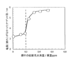
- FIG. 1 shows the relationship between the amount of diffusible hydrogen (mass ppm) and the minimum nugget diameter (mm).
- the steel structure and mechanical properties are also within the scope of the present invention.
- Example 2 Molten steel having the component compositions of steels A to N shown in Table 1 was melted in a converter and made into a slab with a continuous casting machine, heated to 1200 ° C. and then hot-rolled to a finish rolling temperature of 910 ° C., A hot rolled coil was formed at a winding temperature of 560 ° C. Thereafter, a cold rolled coil having a cold pressure ratio of 50% and a thickness of 1.4 mm was obtained.
- a sample of the galvanized steel sheet obtained as described above is collected, and the microstructure (area ratio), yield strength (YS), tensile strength (TS), tensile strength (TS)
- the evaluation method is as follows. As an evaluation of hydrogen embrittlement resistance, the nugget crack of the weld was evaluated.
- Microstructure observation A specimen for microstructural observation was collected from a galvanized steel sheet, and after polishing the L cross section (thickness cross section parallel to the rolling direction), it was corroded with Nital solution and near 1/4 t (t is the total thickness) from the surface with SEM. The images taken by observing three or more visual fields at a magnification of 1500 times were analyzed (the area ratio was measured for each observation visual field, and the average value was calculated). However, since the volume ratio of retained austenite (the volume ratio is regarded as the area ratio) is quantified by the X-ray diffraction intensity, the total of each structure may exceed 100%.
- F means ferrite
- M means martensite
- B bainite
- residual ⁇ means residual austenite.
- Tensile test A JIS No. 5 tensile test piece (JISZ2201) was sampled from a galvanized steel sheet in a direction perpendicular to the rolling direction, and a tensile test was performed at a constant tensile speed (crosshead speed) of 10 mm / min.
- Yield strength (YS) is the value obtained by reading the 0.2% proof stress from the slope of the 150 to 350 MPa stress range, and the tensile strength is the value obtained by dividing the maximum load in the tensile test by the initial cross-sectional area of the parallel part of the specimen. It was.
- the plate thickness in calculating the cross-sectional area of the parallel portion the plate thickness value including the plating thickness was used.
- Tensile strength (TS), yield strength (YS), and elongation (El) were measured, and yield ratio YR and equation (1) were calculated.
- Hydrogen embrittlement resistance As an evaluation of hydrogen embrittlement resistance, the hydrogen embrittlement of the resistance spot welds of steel sheets was evaluated.
- the evaluation method is the same as in Example 1.
- the welding current value was a condition for forming a nugget diameter corresponding to the strength of each steel plate.
- a nugget diameter of 3.8 mm was set at 1100 MPa or more and less than 1250 MPa, and a nugget diameter of 4.8 mm was set at 1250 MPa or more and 1400 MPa or less.
- the distance between the spacers at both ends was 40 mm, and the steel plate and the spacer were secured in advance by welding.
- the non-plating defect means an area in the order of several ⁇ m to several mm, where plating is not present and the steel sheet is exposed.
- the amount of diffusible hydrogen in steel was measured by the same method as in Example 1.
- Table 3 shows the obtained results.
- the inventive examples were all good in TS, YR, surface properties and hydrogen embrittlement resistance. Any of the comparative examples was inferior. Further, from the comparison between the inventive example and the comparative example, the relationship between the amount of diffusible hydrogen and the resistance to hydrogen embrittlement is within the range of the component composition and steel structure of the present invention, and the amount of diffusible hydrogen is 0. When the content is less than 20 ppm by mass, the resistance spot welded nugget crack is evaluated as favorable as hydrogen embrittlement resistance.
- the high-strength galvanized steel sheet of the present invention not only has high tensile strength, but also has a high yield strength ratio and good ductility, and is excellent in the hydrogen embrittlement resistance and surface properties of the material. For this reason, when a high-strength member obtained by using the high-strength galvanized steel sheet of the present invention is applied to a skeleton component of an automobile body, particularly a component around a cabin that affects collision safety, along with improvement of its safety performance, Contributes to weight reduction of vehicle body due to high strength and thinning effect. As a result, the present invention can contribute to environmental aspects such as CO 2 emission.
- the high-strength galvanized steel sheet according to the present invention has good surface properties and plating quality, it can be actively applied to places where corrosion due to rain and snow is a concern, such as undercarriage. For this reason, according to this invention, performance improvement can be expected also about the rust prevention and corrosion resistance of a vehicle body. Such characteristics are effective not only for automobile parts, but also in the fields of civil engineering / architecture and home appliances.
Landscapes
- Chemical & Material Sciences (AREA)
- Engineering & Computer Science (AREA)
- Organic Chemistry (AREA)
- Materials Engineering (AREA)
- Mechanical Engineering (AREA)
- Metallurgy (AREA)
- Physics & Mathematics (AREA)
- Thermal Sciences (AREA)
- Crystallography & Structural Chemistry (AREA)
- Chemical Kinetics & Catalysis (AREA)
- General Chemical & Material Sciences (AREA)
- Oil, Petroleum & Natural Gas (AREA)
- Heat Treatment Of Sheet Steel (AREA)
- Coating With Molten Metal (AREA)
Abstract
Priority Applications (7)
| Application Number | Priority Date | Filing Date | Title |
|---|---|---|---|
| CN202211046507.1A CN115404406A (zh) | 2018-03-30 | 2019-03-29 | 高强度镀锌钢板、高强度部件及它们的制造方法 |
| US17/042,521 US11795531B2 (en) | 2018-03-30 | 2019-03-29 | High-strength galvanized steel sheet, high strength member, and method for manufacturing the same |
| KR1020207028138A KR102400445B1 (ko) | 2018-03-30 | 2019-03-29 | 고강도 아연 도금 강판, 고강도 부재 및 그들의 제조 방법 |
| MX2020010228A MX2020010228A (es) | 2018-03-30 | 2019-03-29 | Chapa de acero galvanizado de alta resistencia, miembro de alta resistencia y metodo para fabricar el mismo. |
| EP19776138.0A EP3757243B1 (fr) | 2018-03-30 | 2019-03-29 | Tôle d'acier galvanisée à résistance élevée, élément à résistance élevée et leurs procédés de fabrication |
| CN201980023902.8A CN111936651A (zh) | 2018-03-30 | 2019-03-29 | 高强度镀锌钢板、高强度部件及它们的制造方法 |
| JP2019537007A JP6631760B1 (ja) | 2018-03-30 | 2019-03-29 | 高強度亜鉛めっき鋼板および高強度部材 |
Applications Claiming Priority (2)
| Application Number | Priority Date | Filing Date | Title |
|---|---|---|---|
| JP2018-068994 | 2018-03-30 | ||
| JP2018068994 | 2018-03-30 |
Publications (1)
| Publication Number | Publication Date |
|---|---|
| WO2019189842A1 true WO2019189842A1 (fr) | 2019-10-03 |
Family
ID=68058512
Family Applications (1)
| Application Number | Title | Priority Date | Filing Date |
|---|---|---|---|
| PCT/JP2019/014221 WO2019189842A1 (fr) | 2018-03-30 | 2019-03-29 | Tôle d'acier galvanisée à résistance élevée, élément à résistance élevée et leurs procédés de fabrication |
Country Status (7)
| Country | Link |
|---|---|
| US (1) | US11795531B2 (fr) |
| EP (1) | EP3757243B1 (fr) |
| JP (2) | JP6631760B1 (fr) |
| KR (1) | KR102400445B1 (fr) |
| CN (2) | CN111936651A (fr) |
| MX (1) | MX2020010228A (fr) |
| WO (1) | WO2019189842A1 (fr) |
Cited By (10)
| Publication number | Priority date | Publication date | Assignee | Title |
|---|---|---|---|---|
| WO2021019947A1 (fr) * | 2019-07-30 | 2021-02-04 | Jfeスチール株式会社 | Feuille d'acier de haute résistance et procédé de fabrication de celle-ci |
| JP6977916B1 (ja) * | 2020-07-14 | 2021-12-08 | Jfeスチール株式会社 | 鋼材及び鋼製品の脱水素方法、並びに、鋼材及び鋼製品の製造方法 |
| WO2022014125A1 (fr) * | 2020-07-14 | 2022-01-20 | Jfeスチール株式会社 | Dispositif de déshydrogénation, système de fabrication d'une tôle d'acier et procédé de fabrication de tôle d'acier |
| JPWO2022014131A1 (fr) * | 2020-07-14 | 2022-01-20 | ||
| WO2022014172A1 (fr) * | 2020-07-14 | 2022-01-20 | Jfeスチール株式会社 | Procédé de déshydrogénation pour matériau d'acier et produit en acier, et procédé de fabrication de matériau d'acier et de produit en acier |
| JP2022072595A (ja) * | 2020-10-30 | 2022-05-17 | Jfeスチール株式会社 | 鋼中水素分析用サンプルの作製方法、鋼中水素分析方法、鋼板の拡散性水素による脆性劣化の予測方法及び鋼板の検査成績証明方法 |
| JP7151948B1 (ja) * | 2021-06-15 | 2022-10-12 | Jfeスチール株式会社 | 高強度亜鉛めっき鋼板および部材ならびにそれらの製造方法 |
| CN115216716A (zh) * | 2022-05-30 | 2022-10-21 | 山东嘉隆新型材料有限公司 | 一种高强度抗压镀锌板 |
| WO2022264585A1 (fr) * | 2021-06-15 | 2022-12-22 | Jfeスチール株式会社 | Tôle d'acier galvanisé à et élément et procédé de fabrication associé |
| WO2023181821A1 (fr) * | 2022-03-25 | 2023-09-28 | Jfeスチール株式会社 | Dispositif de déshydrogénation, système de fabrication d'une tôle d'acier et procédé de fabrication de tôle d'acier |
Families Citing this family (4)
| Publication number | Priority date | Publication date | Assignee | Title |
|---|---|---|---|---|
| EP3872230A1 (fr) * | 2020-02-28 | 2021-09-01 | voestalpine Stahl GmbH | Procédé de fabrication de composants en acier durci doté d'une couche de protection contre la corrosion en alliage de zinc conditionnée |
| CN112251694A (zh) * | 2020-09-25 | 2021-01-22 | 河钢股份有限公司承德分公司 | 一种厚锌层热基镀锌板及其制备方法 |
| EP4269644A4 (fr) * | 2021-03-10 | 2024-03-13 | Nippon Steel Corp | Tôle d'acier laminée à froid et son procédé de fabrication |
| EP4269643A4 (fr) * | 2021-03-10 | 2024-03-13 | Nippon Steel Corp | Tôle d'acier laminée à froid et procédé de fabrication de celle-ci |
Citations (13)
| Publication number | Priority date | Publication date | Assignee | Title |
|---|---|---|---|---|
| JP2006207018A (ja) | 2004-12-28 | 2006-08-10 | Kobe Steel Ltd | 耐水素脆化特性に優れた超高強度薄鋼板 |
| JP2007197819A (ja) | 2005-12-28 | 2007-08-09 | Kobe Steel Ltd | 超高強度薄鋼板 |
| JP2007231373A (ja) | 2006-03-01 | 2007-09-13 | Nippon Steel Corp | 溶接部の耐水素脆性に優れる高強度鋼板及びその製造方法 |
| JP2011111671A (ja) | 2009-11-30 | 2011-06-09 | Nippon Steel Corp | 延性及び耐遅れ破壊特性の良好な引張最大強度900MPa以上を有する高強度鋼板および高強度冷延鋼板の製造方法、高強度亜鉛めっき鋼板の製造方法 |
| JP2011190474A (ja) | 2010-03-11 | 2011-09-29 | Kobe Steel Ltd | 耐水素脆性に優れた超高強度薄鋼板 |
| WO2013047836A1 (fr) * | 2011-09-30 | 2013-04-04 | 新日鐵住金株式会社 | Feuille d'acier galvanisée et son procédé de fabrication |
| JP2013213232A (ja) | 2012-03-30 | 2013-10-17 | Kobe Steel Ltd | 加工性に優れた高降伏比高強度鋼板 |
| WO2015029404A1 (fr) * | 2013-08-26 | 2015-03-05 | Jfeスチール株式会社 | Tôle d'acier galvanisé à chaud à haute résistance et procédé de fabrication de celle-ci |
| JP2015151607A (ja) | 2014-02-18 | 2015-08-24 | Jfeスチール株式会社 | 高強度溶融亜鉛めっき鋼板およびその製造方法 |
| WO2016199922A1 (fr) * | 2015-06-11 | 2016-12-15 | 新日鐵住金株式会社 | Tôle d'acier recuite par galvanisation et procédé permettant de fabriquer cette dernière |
| WO2018124157A1 (fr) * | 2016-12-27 | 2018-07-05 | Jfeスチール株式会社 | Tôle d'acier galvanisée à résistance élevée et son procédé de fabrication |
| WO2018146828A1 (fr) * | 2017-02-10 | 2018-08-16 | Jfeスチール株式会社 | Tôle d'acier galvanisée de haute résistance et son procédé de fabrication |
| JP6525114B1 (ja) * | 2017-11-29 | 2019-06-05 | Jfeスチール株式会社 | 高強度亜鉛めっき鋼板およびその製造方法 |
Family Cites Families (27)
| Publication number | Priority date | Publication date | Assignee | Title |
|---|---|---|---|---|
| CA2513298C (fr) * | 2003-01-15 | 2012-01-03 | Nippon Steel Corporation | Feuille d'acier galvanise a chaud presentant une resistance elevee et methode de production de cette feuille |
| JP4500124B2 (ja) * | 2004-07-23 | 2010-07-14 | 新日本製鐵株式会社 | ホットプレス用めっき鋼板の製造方法 |
| CA2531615A1 (fr) * | 2004-12-28 | 2006-06-28 | Kabushiki Kaisha Kobe Seiko Sho (Kobe Steel, Ltd.) | Tole mince d'acier a haute resistance possedant une resistance elevee a la fragilisation par l'hydrogene |
| CN100510143C (zh) | 2006-05-29 | 2009-07-08 | 株式会社神户制钢所 | 延伸凸缘性优异的高强度钢板 |
| JP5000367B2 (ja) * | 2007-04-13 | 2012-08-15 | 新日本製鐵株式会社 | 耐水素脆化特性に優れた高強度亜鉛めっきボルト |
| RU2510423C2 (ru) * | 2009-08-31 | 2014-03-27 | Ниппон Стил Корпорейшн | Высокопрочная гальванизированная листовая сталь и способ ее изготовления |
| JP5370104B2 (ja) * | 2009-11-30 | 2013-12-18 | 新日鐵住金株式会社 | 耐水素脆化特性に優れた引張最大強度900MPa以上の高強度鋼板および高強度冷延鋼板の製造方法、高強度亜鉛めっき鋼板の製造方法 |
| BR112014007483B1 (pt) * | 2011-09-30 | 2019-12-31 | Nippon Steel & Sumitomo Metal Corp | chapa de aço galvanizado a quente e processo de fabricação da mesma |
| TWI507535B (zh) * | 2011-09-30 | 2015-11-11 | Nippon Steel & Sumitomo Metal Corp | Alloyed molten galvanized steel sheet |
| KR20150029736A (ko) | 2012-07-31 | 2015-03-18 | 제이에프이 스틸 가부시키가이샤 | 성형성 및 형상 동결성이 우수한 고강도 용융 아연 도금 강판, 그리고 그의 제조 방법 |
| CN105940134B (zh) * | 2014-01-29 | 2018-02-16 | 杰富意钢铁株式会社 | 高强度冷轧钢板及其制造方法 |
| CN106164313B (zh) | 2014-03-31 | 2018-06-08 | 杰富意钢铁株式会社 | 高屈强比高强度冷轧钢板及其制造方法 |
| CN106574318B (zh) | 2014-08-07 | 2019-01-08 | 杰富意钢铁株式会社 | 高强度钢板及其制造方法 |
| EP3187607B1 (fr) * | 2014-08-28 | 2019-03-06 | JFE Steel Corporation | Tôle d'acier galvanisé à haute résistance ayant une excellente aptitude à l'étirement des bords, une excellente stabilité dans l'étirement dans le plan de l'aptitude à l'étirement des bords ainsi qu'une excellente aptitude au pliage, et son procédé de production |
| KR101657796B1 (ko) | 2014-12-15 | 2016-09-20 | 주식회사 포스코 | 내지연파괴 특성이 우수한 고강도 강판 및 이의 제조방법 |
| JP5958666B1 (ja) | 2014-12-22 | 2016-08-02 | Jfeスチール株式会社 | 高強度溶融亜鉛めっき鋼板およびその製造方法 |
| KR101647224B1 (ko) * | 2014-12-23 | 2016-08-10 | 주식회사 포스코 | 표면품질, 도금밀착성 및 성형성이 우수한 고강도 용융아연도금강판 및 그 제조방법 |
| WO2016111388A1 (fr) * | 2015-01-07 | 2016-07-14 | 주식회사 포스코 | Feuille d'acier plaquée à très haute résistance ayant une résistance à la traction de 1 300 mpa ou plus et son procédé de fabrication |
| JP6540162B2 (ja) | 2015-03-31 | 2019-07-10 | 日本製鉄株式会社 | 延性および伸びフランジ性に優れた高強度冷延鋼板、高強度合金化溶融亜鉛めっき鋼板、およびそれらの製造方法 |
| JP6249113B2 (ja) * | 2016-01-27 | 2017-12-20 | Jfeスチール株式会社 | 高降伏比型高強度亜鉛めっき鋼板及びその製造方法 |
| WO2017131055A1 (fr) | 2016-01-27 | 2017-08-03 | Jfeスチール株式会社 | Tôle d'acier galvanisé haute résistance à rapport d'élasticité élevé et son procédé de production |
| MX2018009099A (es) | 2016-01-27 | 2018-09-03 | Jfe Steel Corp | Lamina de acero galvanizada de alta resistencia de alta relacion de cedencia y metodo para fabricar la misma. |
| JP2017145441A (ja) * | 2016-02-16 | 2017-08-24 | 日新製鋼株式会社 | 黒色表面被覆高強度鋼板およびその製造方法 |
| JP6526114B2 (ja) | 2017-06-16 | 2019-06-05 | ファナック株式会社 | 鉄心およびコイルを備えたリアクトル |
| JP6544494B1 (ja) | 2017-11-29 | 2019-07-17 | Jfeスチール株式会社 | 高強度亜鉛めっき鋼板およびその製造方法 |
| MX2020010279A (es) | 2018-03-30 | 2020-10-28 | Jfe Steel Corp | Lamina de acero galvanizada de alta resistencia, miembro de alta resistencia, y metodo para la fabricacion de los mismos. |
| CN114008234A (zh) * | 2019-07-30 | 2022-02-01 | 杰富意钢铁株式会社 | 高强度钢板及其制造方法 |
-
2019
- 2019-03-29 EP EP19776138.0A patent/EP3757243B1/fr active Active
- 2019-03-29 KR KR1020207028138A patent/KR102400445B1/ko active IP Right Grant
- 2019-03-29 MX MX2020010228A patent/MX2020010228A/es unknown
- 2019-03-29 US US17/042,521 patent/US11795531B2/en active Active
- 2019-03-29 WO PCT/JP2019/014221 patent/WO2019189842A1/fr unknown
- 2019-03-29 CN CN201980023902.8A patent/CN111936651A/zh active Pending
- 2019-03-29 CN CN202211046507.1A patent/CN115404406A/zh active Pending
- 2019-03-29 JP JP2019537007A patent/JP6631760B1/ja active Active
- 2019-10-17 JP JP2019190132A patent/JP6787466B2/ja active Active
Patent Citations (13)
| Publication number | Priority date | Publication date | Assignee | Title |
|---|---|---|---|---|
| JP2006207018A (ja) | 2004-12-28 | 2006-08-10 | Kobe Steel Ltd | 耐水素脆化特性に優れた超高強度薄鋼板 |
| JP2007197819A (ja) | 2005-12-28 | 2007-08-09 | Kobe Steel Ltd | 超高強度薄鋼板 |
| JP2007231373A (ja) | 2006-03-01 | 2007-09-13 | Nippon Steel Corp | 溶接部の耐水素脆性に優れる高強度鋼板及びその製造方法 |
| JP2011111671A (ja) | 2009-11-30 | 2011-06-09 | Nippon Steel Corp | 延性及び耐遅れ破壊特性の良好な引張最大強度900MPa以上を有する高強度鋼板および高強度冷延鋼板の製造方法、高強度亜鉛めっき鋼板の製造方法 |
| JP2011190474A (ja) | 2010-03-11 | 2011-09-29 | Kobe Steel Ltd | 耐水素脆性に優れた超高強度薄鋼板 |
| WO2013047836A1 (fr) * | 2011-09-30 | 2013-04-04 | 新日鐵住金株式会社 | Feuille d'acier galvanisée et son procédé de fabrication |
| JP2013213232A (ja) | 2012-03-30 | 2013-10-17 | Kobe Steel Ltd | 加工性に優れた高降伏比高強度鋼板 |
| WO2015029404A1 (fr) * | 2013-08-26 | 2015-03-05 | Jfeスチール株式会社 | Tôle d'acier galvanisé à chaud à haute résistance et procédé de fabrication de celle-ci |
| JP2015151607A (ja) | 2014-02-18 | 2015-08-24 | Jfeスチール株式会社 | 高強度溶融亜鉛めっき鋼板およびその製造方法 |
| WO2016199922A1 (fr) * | 2015-06-11 | 2016-12-15 | 新日鐵住金株式会社 | Tôle d'acier recuite par galvanisation et procédé permettant de fabriquer cette dernière |
| WO2018124157A1 (fr) * | 2016-12-27 | 2018-07-05 | Jfeスチール株式会社 | Tôle d'acier galvanisée à résistance élevée et son procédé de fabrication |
| WO2018146828A1 (fr) * | 2017-02-10 | 2018-08-16 | Jfeスチール株式会社 | Tôle d'acier galvanisée de haute résistance et son procédé de fabrication |
| JP6525114B1 (ja) * | 2017-11-29 | 2019-06-05 | Jfeスチール株式会社 | 高強度亜鉛めっき鋼板およびその製造方法 |
Cited By (17)
| Publication number | Priority date | Publication date | Assignee | Title |
|---|---|---|---|---|
| WO2021019947A1 (fr) * | 2019-07-30 | 2021-02-04 | Jfeスチール株式会社 | Feuille d'acier de haute résistance et procédé de fabrication de celle-ci |
| JP6901050B1 (ja) * | 2019-07-30 | 2021-07-14 | Jfeスチール株式会社 | 高強度鋼板およびその製造方法 |
| JP7259974B2 (ja) | 2020-07-14 | 2023-04-18 | Jfeスチール株式会社 | 連続焼鈍装置及び連続溶融亜鉛めっき装置、並びに鋼板の製造方法 |
| JP6977916B1 (ja) * | 2020-07-14 | 2021-12-08 | Jfeスチール株式会社 | 鋼材及び鋼製品の脱水素方法、並びに、鋼材及び鋼製品の製造方法 |
| JPWO2022014131A1 (fr) * | 2020-07-14 | 2022-01-20 | ||
| WO2022014131A1 (fr) * | 2020-07-14 | 2022-01-20 | Jfeスチール株式会社 | Appareil de recuit continu, appareil de galvanisation par immersion à chaud continue et procédé de fabrication de tôle d'acier |
| WO2022014172A1 (fr) * | 2020-07-14 | 2022-01-20 | Jfeスチール株式会社 | Procédé de déshydrogénation pour matériau d'acier et produit en acier, et procédé de fabrication de matériau d'acier et de produit en acier |
| JP7006857B1 (ja) * | 2020-07-14 | 2022-01-24 | Jfeスチール株式会社 | 脱水素装置及び鋼板の製造システム、並びに鋼板の製造方法 |
| WO2022014125A1 (fr) * | 2020-07-14 | 2022-01-20 | Jfeスチール株式会社 | Dispositif de déshydrogénation, système de fabrication d'une tôle d'acier et procédé de fabrication de tôle d'acier |
| JP2022072595A (ja) * | 2020-10-30 | 2022-05-17 | Jfeスチール株式会社 | 鋼中水素分析用サンプルの作製方法、鋼中水素分析方法、鋼板の拡散性水素による脆性劣化の予測方法及び鋼板の検査成績証明方法 |
| JP7327353B2 (ja) | 2020-10-30 | 2023-08-16 | Jfeスチール株式会社 | 鋼中水素分析用サンプルの作製方法、鋼中水素分析方法、鋼板の拡散性水素による脆性劣化の予測方法及び鋼板の検査成績証明方法 |
| JP7151948B1 (ja) * | 2021-06-15 | 2022-10-12 | Jfeスチール株式会社 | 高強度亜鉛めっき鋼板および部材ならびにそれらの製造方法 |
| WO2022264585A1 (fr) * | 2021-06-15 | 2022-12-22 | Jfeスチール株式会社 | Tôle d'acier galvanisé à et élément et procédé de fabrication associé |
| WO2023181821A1 (fr) * | 2022-03-25 | 2023-09-28 | Jfeスチール株式会社 | Dispositif de déshydrogénation, système de fabrication d'une tôle d'acier et procédé de fabrication de tôle d'acier |
| JP7460032B2 (ja) | 2022-03-25 | 2024-04-02 | Jfeスチール株式会社 | 脱水素装置及び鋼板の製造システム、並びに鋼板の製造方法 |
| CN115216716A (zh) * | 2022-05-30 | 2022-10-21 | 山东嘉隆新型材料有限公司 | 一种高强度抗压镀锌板 |
| CN115216716B (zh) * | 2022-05-30 | 2023-09-08 | 山东嘉隆新型材料有限公司 | 一种高强度抗压镀锌板 |
Also Published As
| Publication number | Publication date |
|---|---|
| KR20200124740A (ko) | 2020-11-03 |
| US11795531B2 (en) | 2023-10-24 |
| JP6631760B1 (ja) | 2020-01-15 |
| EP3757243A1 (fr) | 2020-12-30 |
| EP3757243B1 (fr) | 2022-05-04 |
| JP2020045568A (ja) | 2020-03-26 |
| US20210010115A1 (en) | 2021-01-14 |
| EP3757243A4 (fr) | 2020-12-30 |
| JPWO2019189842A1 (ja) | 2020-04-30 |
| MX2020010228A (es) | 2020-11-06 |
| JP6787466B2 (ja) | 2020-11-18 |
| KR102400445B1 (ko) | 2022-05-20 |
| CN115404406A (zh) | 2022-11-29 |
| CN111936651A (zh) | 2020-11-13 |
Similar Documents
| Publication | Publication Date | Title |
|---|---|---|
| JP6787466B2 (ja) | 高強度亜鉛めっき鋼板の製造方法、及び高強度部材の製造方法 | |
| JP6525114B1 (ja) | 高強度亜鉛めっき鋼板およびその製造方法 | |
| JP6777173B2 (ja) | スポット溶接用高強度亜鉛めっき鋼板 | |
| KR102173601B1 (ko) | 고강도 박강판 및 그 제조 방법 | |
| JP5194878B2 (ja) | 加工性および溶接性に優れる高強度溶融亜鉛めっき鋼板およびその製造方法 | |
| KR102316660B1 (ko) | 열간 프레스 부재 및 그 제조 방법 그리고 열간 프레스용 냉연강판 및 그 제조 방법 | |
| WO2010126161A1 (fr) | Tôle d'acier zinguée à chaud à haute résistance présentant une excellente aptitude au façonnage, une excellente aptitude au soudage et d'excellentes propriétés de résistance à la fatigue, et procédé de fabrication de cette dernière | |
| EP2527484B1 (fr) | Procédé de production d'une tôle en acier galvanisé à haute résistance présentant une excellente aptitude au traitement et une excellente soudabilité par points | |
| CN109563593B (zh) | 高强度钢板及其制造方法 | |
| CN114207169B (zh) | 钢板及其制造方法 | |
| US20220064752A1 (en) | High-strength cold-rolled steel sheet and production method for same | |
| JP4370795B2 (ja) | 溶融亜鉛めっき鋼板の製造方法 | |
| JP7311808B2 (ja) | 鋼板及びその製造方法 |
Legal Events
| Date | Code | Title | Description |
|---|---|---|---|
| ENP | Entry into the national phase |
Ref document number: 2019537007 Country of ref document: JP Kind code of ref document: A |
|
| 121 | Ep: the epo has been informed by wipo that ep was designated in this application |
Ref document number: 19776138 Country of ref document: EP Kind code of ref document: A1 |
|
| ENP | Entry into the national phase |
Ref document number: 2019776138 Country of ref document: EP Effective date: 20200921 |
|
| ENP | Entry into the national phase |
Ref document number: 20207028138 Country of ref document: KR Kind code of ref document: A |