WO2014156470A1 - 打込機 - Google Patents
打込機 Download PDFInfo
- Publication number
- WO2014156470A1 WO2014156470A1 PCT/JP2014/055092 JP2014055092W WO2014156470A1 WO 2014156470 A1 WO2014156470 A1 WO 2014156470A1 JP 2014055092 W JP2014055092 W JP 2014055092W WO 2014156470 A1 WO2014156470 A1 WO 2014156470A1
- Authority
- WO
- WIPO (PCT)
- Prior art keywords
- weight
- plunger
- elastic body
- moved
- driving
- Prior art date
- Legal status (The legal status is an assumption and is not a legal conclusion. Google has not performed a legal analysis and makes no representation as to the accuracy of the status listed.)
- Ceased
Links
Images




Classifications
-
- B—PERFORMING OPERATIONS; TRANSPORTING
- B25—HAND TOOLS; PORTABLE POWER-DRIVEN TOOLS; MANIPULATORS
- B25C—HAND-HELD NAILING OR STAPLING TOOLS; MANUALLY OPERATED PORTABLE STAPLING TOOLS
- B25C1/00—Hand-held nailing tools; Nail feeding devices
- B25C1/06—Hand-held nailing tools; Nail feeding devices operated by electric power
-
- B—PERFORMING OPERATIONS; TRANSPORTING
- B25—HAND TOOLS; PORTABLE POWER-DRIVEN TOOLS; MANIPULATORS
- B25F—COMBINATION OR MULTI-PURPOSE TOOLS NOT OTHERWISE PROVIDED FOR; DETAILS OR COMPONENTS OF PORTABLE POWER-DRIVEN TOOLS NOT PARTICULARLY RELATED TO THE OPERATIONS PERFORMED AND NOT OTHERWISE PROVIDED FOR
- B25F5/00—Details or components of portable power-driven tools not particularly related to the operations performed and not otherwise provided for
- B25F5/006—Vibration damping means
Definitions
- the present invention relates to a driving machine for driving a stopper such as a nail or a pin into a material to be driven such as wood or gypsum board.
- a driving machine that moves a driving tool using a restoring force of an elastic body such as a coil spring to drive a stopper into a driven material is known. Some of these types of driving machines are equipped with a mechanism for absorbing or reducing the reaction of driving the stopper. *
- Patent Document 1 when an active member (active device) having a nail driving tool moves in the nail driving direction, a weight (weight device) that moves in a direction opposite to the driving direction to reduce a reaction at the time of driving. ) Is described.
- a rack gear is formed on each of the active member and the weight.
- a common pinion gear that is always meshed with each rack gear is provided between the active member and the weight.
- the pinion gear rotates in a predetermined direction
- the active member is moved in the direction opposite to the driving direction, and the weight is moved in the driving direction.
- the weight moves in the direction opposite to the driving direction along with the rotation of the pinion gear, and the recoil during driving is reduced.
- the active member and the weight are interlocked. Specifically, the active member and the weight are connected via a common pinion gear. Therefore, when the movement of the active member in the driving direction suddenly stops for some reason, a large impact is applied to the teeth of the rack gear and the pinion gear engaged with each other, and one or both of the gears may be damaged.
- Patent Document 1 also describes a form in which an active member and a weight are connected to each other by a common wire (pulling member).
- a common wire pulse (pulling member)
- An object of the present invention is to further improve the durability of the driving machine.
- a driving machine is a driving machine for driving a stopper into a material to be driven, and is moved in a first direction parallel to a driving direction of the stopper by urging by a first elastic body.
- a plunger that moves in a second direction opposite to the first direction against the bias of the first elastic body; and a plunger that is moved in the second direction by the bias of the second elastic body; And a weight that moves in the first direction against urging.
- the weight is moved in the second direction when the plunger is moved in the first direction, and is moved in the first direction when the plunger is moved in the second direction.
- the weights move in the first direction and the second direction independently of each other.
- the drive that generates a driving force that moves the plunger against the bias of the first elastic body and moves the weight against the bias of the second elastic body.
- a power source a rotating body that is rotationally driven by the driving source, a first power transmission path provided between the rotating body and the plunger, and a second power path provided between the rotating body and the weight.
- a power transmission path A power transmission path.
- the first elastic body is disposed in a cylinder in which the plunger is accommodated so as to be reciprocally movable, and the second elastic body and the weight are disposed around the cylinder. . *
- the first elastic body and the second elastic body are coil springs
- the weight has a cylindrical shape
- the first elastic body, the second elastic body, and the weight are coaxial. Be placed.
- the plunger, the weight, and the first elastic body are arranged coaxially.
- the first power transmission path includes a gear group including a gear that rotates integrally with the rotating body, a drum that is rotationally driven by a driving force transmitted through the gear group, and one end. Is connected to the drum, and the other end is connected to the plunger.
- the second power transmission path is configured by an engaging portion that rotates integrally with the rotating body and switches between an engaged state engaged with the weight and a non-engaged state not engaged with the weight.
- a clutch mechanism that is provided in the first power transmission path and switches between a fastening state where driving force is transmitted to the plunger and a released state where driving force is not transmitted to the plunger, The engaging portion is switched from the engaged state to the disengaged state at the same time or immediately after the clutch mechanism is switched from the engaged state to the released state.
- a first engagement portion and a second engagement portion that sequentially engage with the weight are provided.
- the first engaging portion engages with the weight prior to the second engaging portion to move the weight in the second direction
- the second engaging portion is the first engaging portion. Then, it engages with the weight and further moves the weight in the second direction.
- the durability of the driving machine can be further improved.
- (A) is sectional drawing which shows the engagement state of a weight and an engagement pin
- (B) is a perspective view of a weight
- (A) to (D) are schematic views showing changes in the engagement state between the weight and the engagement pin.
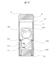
- FIG. 12 is a partial cross-sectional view taken along the line CC shown in FIG. 11.
- (A) to (F) are schematic views showing changes in the engagement state between the plunger and weight and the cam roller.
- the driving machine according to the present embodiment is a nailing machine that drives a nail, which is a stopper, into a driven material such as wood or gypsum board by a reciprocatingly driven driver blade.
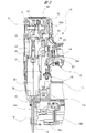
- a nailing machine 1A shown in FIG. 1 has a housing 10 made of a resin such as nylon or polo carbonate.
- a handle 11 is provided integrally with the housing 10, and a trigger switch 12 is provided on the handle 11.
- a detachable battery 13 is attached to the back of the handle 11.
- a nose portion 14 is provided at the lower portion of the housing 10, and a magazine 15 extending in the same direction as the handle 11 is provided behind the nose portion 14.
- a plurality of nails 100 aligned and connected are loaded and held.
- the nail 100 held in the magazine 15 is supplied to the injection port 14 a in the nose portion 14 via a supply path 16 a provided in the blade guide 16.
- an electric motor 17 as a drive source and a cylinder 23 in which an integrated plunger 21 and driver blade 22 are housed so as to reciprocate.
- a substantially cylindrical weight 24 capable of reciprocating along the cylinder 23 is disposed inside the housing 10 and around the cylinder 23.
- a piston bumper 18 as a cushioning material for reducing the impact when the plunger 21 is lowered is disposed at the lower inner end of the housing 10.
- the piston bumper 18 is made of a soft rubber or a resin such as urethane, and is disposed below the plunger 21 and contacts the lower end surface of the plunger 21.
- a power supply control unit 19 and various cables 20 for supplying electric power stored in the battery 13 to the electric motor 17 and the like are provided inside the housing 10. *
- a coil spring 25 as a first elastic body is accommodated in the cylinder 23 in which the plunger 21 and the driver blade 22 are accommodated, and a coil spring 30 as a second elastic body is disposed around the cylinder 23. Yes.
- the plunger 21, the coil springs 25 and 30, and the weight 24 are arranged on the same axis. That is, the central axes of the plunger 21, the coil springs 25 and 30, and the weight 24 are aligned on the same straight line.
- the illustrated plunger 21 and driver blade 22 are movable integrally in a first direction parallel to the driving direction of the nail 100 and a second direction opposite to the first direction. That is, the plunger 21 and the driver blade 22 can reciprocate in the first direction and the second direction.
- the driver blade 22 moves in the first direction
- the driver blade 22 drives the leading nail 100 of the connecting nail loaded in the magazine 15 and drives it into the workpiece W.
- the lower side of the paper is the first direction (the driving direction)
- the upper side of the paper is the second direction. Therefore, in the following description, the first direction may be referred to as “downward” and the second direction may be referred to as “upward”. *
- the electric motor 17 includes an output shaft 17a as a rotating shaft portion.
- the electric motor 17 is disposed such that the axial direction of the output shaft 17a is perpendicular to the first direction and the second direction. That is, the output shaft 17a of the electric motor 17 is parallel to the front-rear direction of the nailing machine body.
- a first pulley 41 is provided on the output shaft 17 a of the electric motor 17, and a second pulley 42 is provided above the first pulley 41.
- One end side of the rotation shaft 43 is fixed to the center of the second pulley 42, and the other end side of the rotation shaft 43 protrudes outward from the first side surface of the second pulley 42.
- the end of the protruding portion of the rotating shaft 43 is rotatably supported by a bearing 44, and a power transmission belt 45 is wound around the first pulley 41 and the second pulley 42. Therefore, when the electric motor 17 operates, the first pulley 41 and the second pulley 42 rotate. That is, the second pulley 42 is a rotating body that is rotationally driven by the electric motor 17.
- the first stage gear 50 a of the gear group constituting the speed reduction mechanism 50 is fixed to the protruding portion of the rotation shaft 43 of the second pulley 42. That is, the gear 50 a constituting the speed reduction mechanism 50 rotates integrally with the second pulley 42.
- the last gear 50 b of the gear group constituting the speed reduction mechanism 50 is connected to the clutch mechanism 60 disposed on the upper portion of the housing 10.
- the clutch mechanism 60 is interposed between the final stage gear 50 b of the speed reduction mechanism 50 and the drive shaft 71 of the drum 70, and the driving force output from the speed reduction mechanism 50 is transmitted to the drive shaft 71 of the drum 70.
- the fastening state and the releasing state in which the driving force output from the speed reduction mechanism 50 is not transmitted to the driving shaft 71 of the drum 70 are alternately switched.
- One end of a wire 72 is connected to the drum 70, and the other end of the wire 72 is connected to the plunger 21.
- the driving force is transmitted to the drive shaft 71 of the drum 70 via the speed reduction mechanism 50 and the clutch mechanism 60 in the engaged state, and the drum 70 is moved in a predetermined direction. Rotate to.
- the drum 70 rotates in a predetermined direction
- the wire 72 is wound up, and the plunger 21 connected to the wire 72 moves up in the cylinder 23.
- the first power transmission path is configured between the second pulley 42 and the plunger 21 by the gear group constituting the speed reduction mechanism 50, the clutch mechanism 60, the drum 70, the wire 72, and the like, and is transmitted through this path.
- the plunger 21 and the driver blade 22 are moved upward (second direction) by the driving force.
- the plunger 21 rising in the cylinder 23 rises while compressing the coil spring 25 accommodated in the cylinder 23. In other words, the plunger 21 moves upward against the bias of the coil spring 25.
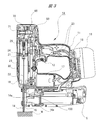
- the plunger 21 shown in FIG. 1 rises to the position shown in FIG. 3 against the bias of the coil spring 25. That is, the position shown in FIG. 1 is the bottom dead center of the plunger 21, the position shown in FIG. 3 is the top dead center of the plunger 21, and the plunger 21 is driven through the first power transmission path. Move from bottom dead center to top dead center by force. *
- the clutch mechanism 60 is switched from the engaged state to the released state.
- the connection between the speed reduction mechanism 50 and the drive shaft 71 of the drum 70 is released, and the drive shaft 71 of the drum 70 becomes free.
- the plunger 21 is pushed down by the elastic restoring force of the compressed coil spring 25. That is, the plunger 21 is moved downward (first direction) by the bias of the coil spring 25. In other words, the plunger 21 descends all at once to the position (bottom dead center) shown in FIG.
- the driver blade 22 is also lowered, and the nail 100 supplied from the magazine 15 is driven into the driven material W.
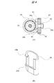
- a first engagement portion and a second engagement portion are provided on the second side surface (side surface opposite to the first side surface) of the second pulley 42.
- a first engagement pin 81 and a second engagement pin 82 extending in the direction opposite to the rotation shaft 43 are provided on the second side surface of the second pulley 42.
- the first engagement pin 81 is longer than the second engagement pin 82. That is, the protruding length of the first engaging pin 81 with respect to the second side surface of the second pulley 42 is longer than the protruding length of the second engaging pin 82.
- the weight 24 has a substantially cylindrical shape with a part cut away.
- the weight 24 is formed with a first engagement protrusion 24a with which the first engagement pin 81 engages and a second engagement protrusion 24b with which the second engagement pin 82 engages.
- the protruding length of the first engaging protrusion 24a with respect to the outer peripheral surface of the weight is shorter than the protruding length of the second engaging protrusion 24b.
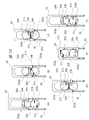
- the first engagement pin 81 and the second engagement pin 82 are sequentially engaged with the weight 24 as the second pulley 42 rotates.
- FIGS. 5 (A) to (D) a specific description will be given with reference to FIGS. 5 (A) to (D).
- the first engagement pin 81 is placed on the first engagement protrusion 24a of the weight 24 from above. Abut and engage.
- FIG. 5A when the first engagement pin 81 is not in contact with the first engagement protrusion 24a, the weight 24 is in the position shown in FIG. Further, as shown in FIG. 5B, even if the first engagement pin 81 contacts the first engagement protrusion 24a, the first engagement pin 81 still presses the first engagement protrusion 24a. When not, the weight 24 is in the position shown in FIG. *
- the second engagement pin 82 comes into contact with and engages with the second engagement protrusion 24b of the weight 24 from above as shown in FIG.
- the weight 24 is further pushed down and the coil spring 30 is further compressed.
- the first engagement pin 81 is separated from the first engagement protrusion 24a. That is, the engagement between the first engagement pin 81 and the first engagement protrusion 24a is released.
- the engagement between the second engagement pin 82 and the second engagement protrusion 24b is maintained, and when the second pulley 42 shown in FIG. 5D rotates in the direction of the arrow, the weight 24 is further pushed down. , Descends to the position shown in FIG. In this way, the first engagement pin 81 and the second engagement pin 82 are sequentially engaged with the weight 24. Specifically, the first engagement pin 81 engages with the weight 24 prior to the second engagement pin 82, and pushes down the weight 24 against the bias of the coil spring 30. The second engagement pin 82 engages with the weight 24 next to the first engagement pin 81, and further pushes down the weight 24 against the bias of the coil spring 30.
- the first engagement pin 81 and the second engagement pin 82 cooperate to push down the weight 24 from the position shown in FIG. 1 to the position shown in FIG. That is, the position shown in FIG. 1 is the top dead center of the weight 24, and the position shown in FIG. *
- the first engagement pin 81 and the second engagement pin 82 projecting from the second pulley 42 constitute the second power transmission path between the second pulley 42 and the weight 24.
- the weight 24 is moved from the top dead center to the bottom dead center by the driving force transmitted through the top dead center. At this time, the weight 24 moves while compressing the coil spring 30. In other words, the weight 24 moves downward against the bias of the coil spring 30. It is clear from the above description that the plunger 21 moves from the bottom dead center to the top dead center while the weight 24 moves from the top dead center to the bottom dead center with the rotation of the second pulley 42. That is, the weight 24 moves downward when the plunger 21 moves upward. *
- the reaction force at the time of driving is absorbed by the reaction force when the weight 24 rises as described above.
- the reaction absorption mechanism will be described in detail.
- the plunger 21 shown in FIG. 3 is at the top dead center, and the weight 24 is at the bottom dead center.
- the plunger 21 is pulled up in a direction (upward) away from the injection port 14 a against the bias of the coil spring 25.
- the weight 24 is pushed down in a direction (downward) close to the injection port 14a against the bias of the coil spring 30.
- the urging force of the coil spring 25 and the coil spring 30 is received by the housing 10, and the balance is maintained. That is, the biasing force of the coil spring 25 and the biasing force of the coil spring 30 are balanced.
- the plunger 21 starts moving in the direction of approaching the injection port 14a by the urging of the coil spring 25. That is, the plunger 21 starts to descend.
- the engagement between the second engagement pin 82 provided on the second pulley 42 and the second engagement protrusion 24b provided on the weight 24 is released, and the weight 24 becomes free (FIG. 5). reference).
- the free weight 24 starts moving in a direction away from the injection port 14 a by the bias of the coil spring 30. That is, the weight 24 starts to rise.
- the weight 24 starts to rise due to the bias of the coil spring 30 at the same time as the plunger 21 starts to fall.
- the coil spring 30 biases the weight 24 in a direction away from the injection port 14a. Accordingly, an urging reaction force is generated at a portion receiving the coil spring 30 on the side opposite to the weight 24. That is, a force (f2) that attempts to bring the nail driver 1A close to the workpiece W is generated, the force (f1) is canceled, and the reaction is absorbed or reduced.
- the clutch mechanism 60 shown in FIG. 1 is switched from the released state to the engaged state in accordance with the rotation of the second pulley 42 shown in FIG. Further, the first engagement pin 81 and the second engagement pin 82 return to the positions shown in FIG. 5B, engage with the weight 24 again, and push the weight 24 down. That is, the first engagement pin 81 and the second engagement pin 82 are not engaged with the weight 24 and the engagement state engaged with the weight 24 at the timing when the clutch mechanism 60 is switched between the engaged state and the released state. Switch to disengaged state. *
- the plunger 21 is moved in the first direction (driving direction) by the urging of the first elastic body, and is driven in the second direction by the driving force transmitted through the first power transmission path. It is moved in the direction opposite to the driving direction.
- the weight 24 is moved in the second direction (opposite to the driving direction) by the urging of the second elastic body, and is moved in the first direction (driving direction) by the driving force transmitted through the second power transmission path. Moved.
- the first power transmission path and the second power transmission path are independent of each other. That is, the plunger 21 and the weight 24 reciprocate in the first direction and the second direction independently of each other. Therefore, even if the movement of the plunger 21 in the first direction suddenly stops for some reason, the movement of the weight 24 in the second direction is not affected.
- the plunger 21, the weight 24, and the coil spring 25 as the first elastic body are arranged coaxially. Accordingly, the reaction force when the coil spring 25 urges the plunger 21 during the driving operation and the repulsive force that the driver blade 22 receives from the nail 100 or the driven material W and the force due to the movement of the weight 24 act. It is close to the axis to be operated and the generation of moment can be suppressed.
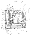
- the driving machine according to the present embodiment is a nailing machine that drives a nail, which is a stopper, into a driven material such as wood or gypsum board by a reciprocating driver blade, and the nailing machine according to the first embodiment. It has the same basic structure as the machine 1A. Therefore, differences from the nailing machine 1A according to the first embodiment will be described below, and descriptions of common points will be omitted. Also, among the configurations shown in the drawings referred to in the following description, the same reference numerals are used for the same or substantially the same configurations as those shown in FIGS. *
- FIG. 6 is a cross-sectional view of the nailing machine 1B according to the present embodiment, in which the illustrated plunger 21 is at the bottom dead center and the weight 24 is at the top dead center.
- FIG. 7 is another cross-sectional view of the nailing machine 1B according to the present embodiment. The illustrated plunger 21 is at the top dead center and the weight 24 is at the bottom dead center.
- a connecting portion 21 a that engages with the driver blade 22 protrudes from the side of the plunger 21, and the plunger 21, the driver blade 22, Are connected. Therefore, the driver blade 22 also moves (lifts) as the plunger 21 moves (lifts).
- a guide hole 21b through which a guide shaft 90 provided in the housing 10 passes is provided in the center of the plunger 21, and the plunger 21 follows the guide of the guide shaft 90 in the first direction and the second direction in the housing 10. Move back and forth in the direction. That is, the plunger 21 and the driver blade 22 move up and down within the housing 10.
- FIG. 8 is an enlarged cross-sectional view of the vicinity of the drive cam 200 shown in FIGS.
- FIG. 9A is a partial cross-sectional view along the line AA shown in FIG. 6, and
- FIG. 9B is a partial cross-sectional view along the line BB shown in FIG.
- a first locking portion 21 c and a second locking portion 21 d that are engaged with the drive cam 200 protrude from the side portion of the plunger 21.
- the first locking portion 21c and the second locking portion 21d protrude in the direction opposite to the protruding direction of the connecting portion 21a.
- locking part 21d are provided in the mutually different height (relative position with the injection port 14a). Specifically, the first locking portion 21c is provided at a position closer to the injection port 14a than the second locking portion 21d. In other words, the first locking portion 21c is provided at a position lower than the second locking portion 21d.
- the plunger 21 shown in FIG. 6 is pushed up to the position shown in FIG. 7 against the bias of the coil spring 25 by the drive cam 200 that is rotationally driven by the electric motor 17.
- the electric motor 17 is driven when the trigger switch 12 is operated, and is stopped when the plunger 21 is detected to be raised to a predetermined position by a micro switch (not shown). In other words, when the trigger switch 12 is operated, the electric motor 17 continues to operate until the plunger 21 rises to a predetermined position.
- the power supply control unit 19 includes a CPU, a RAM, and the like, and controls the electric motor 17 based on signals output from the trigger switch 12 and the microswitch. *
- the drive cam 200 pushes up the plunger 21 by rotating in a state of being engaged with the plunger 21.
- the plunger 21 is moved by the bias of the coil spring 25, and the driver blade 22 connected to the plunger 21 is also moved. That is, the driver blade 22 rapidly descends toward the injection port 14a, and the nail 100 supplied from the magazine 15 shown in FIG. 7 is driven out. This will be specifically described below. *
- a first gear 202 and a second gear 203 that are rotating bodies constituting the drive cam 200 are rotatably attached to a gear holder 201 fixed to the housing 10.
- a planetary gear mechanism is provided between the first gear 202 and the output shaft 17a of the electric motor 17, and the first gear 202 and the second gear 203 are always meshed with each other.
- the first gear 202 is provided with a cam roller 202a
- the second gear 203 is provided with a cam roller 203a.
- the first gear 202 and the second gear 203 are arranged side by side, and the first gear 202 is arranged closer to the injection port 14a than the second gear 203. That is, the first gear 202 is disposed at a position lower than the second gear 203.
- the plunger 21 shown in FIG. 6 is engaged with the cam rollers 202a and 203a in this order, the cam roller 202a of the first gear 202 and the cam roller 203a of the second gear 203, and is gradually pushed up.
- the cam rollers 202a and 203a are composed of pins that protrude from the side surfaces of the first gear 202 and the second gear 203 and rollers that are rotatably mounted on the tips of the pins.
- the weight 24 is disposed between the plunger 21 and the drive cam 200, and is guided by a guide wall 31 that extends along the moving direction of the plunger 21. Thus, it can move in parallel with the plunger 21.
- the drive cam 200 pushes down the weight 24 by rotating while being engaged with the weight 24.
- the weight 24 is moved in the direction opposite to the moving direction of the plunger 21 by the bias of the coil spring 30. That is, the weight 24 rises in a direction away from the injection port 14a. This will be specifically described below.
- the weight 24 engages with the first engagement protrusion 24a that engages with the cam roller 203a protruding from the second gear 203 and the cam roller 202a that protrudes from the first gear 202.
- a second engagement protrusion 24b is formed.
- the weight 24 engages with the cam rollers 202a and 203a in the order of the cam roller 203a of the second gear 203 and the cam roller 202a of the first gear 202, and is gradually pushed down.
- the plunger 21 (FIG. 6) engages with the cam rollers 202a and 203a in the order of the cam roller 202a of the first gear 202 and the cam roller 203a of the second gear 203, and is gradually pushed up. That is, the driving cam 200 gradually pushes down the weight 24 while gradually pushing up the plunger 21.
- the weight 24 shown in FIG. 10 (F) is at the top dead center. That is, the position of the weight 24 shown in FIG. 10F is the same as the position shown in FIG. When the weight 24 is at the position (top dead center) shown in FIG. 6, the plunger 21 shown in FIG. 6 is at the bottom dead center. That is, the driving of the nail 100 by the driver blade 22 is completed. *
- the plunger 21 is further pushed up as the first gear 202 rotates, and the weight 24 is pushed down further as the second gear 203 rotates. That is, the plunger 21, the driver blade 22 and the weight 24 which are in the position shown in FIG. 6 move to the positions shown in FIG.
- the cam roller 203a moves to the highest position, the engagement between the cam roller 203a and the second locking portion 21d of the plunger 21 is released.
- the cam roller 202a reaches the lowest position, and the cam roller 202a and the weight The engagement with the 24 second engagement protrusions 24b is also released.
- the engagement between the plunger 21 and the weight 24 and the drive cam 200 is sequentially released at an extremely short interval. Accordingly, the plunger 21 starts to descend due to the bias of the coil spring 25 shown in FIG. 7, and immediately after that, the weight 24 starts to rise due to the bias of the coil spring 30. As a result, the driver blade 22 connected to the plunger 21 moves toward the injection port 14a and the nail 100 is driven out, and the weight 24 moves in the direction away from the injection port 14a and the reaction caused by the nail driving. Is absorbed. As described above, when the weight 24 starts to rise, the engagement between the plunger 21 and the weight 24 and the drive cam 200 is released.
- one cam roller is provided for each of the first gear 202 and the second gear 203.
- the first gear 202 is provided with a cam roller 202a and a cam roller 202b
- the second gear 203 is provided with a cam roller 203a.
- the cam roller 202b is longer than the cam roller 202a. That is, the protruding length of the cam roller 202b with respect to the side surface of the first gear 202 is longer than the protruding length of the cam roller 202a.
- the lengths of the first locking portion 21c and the second locking portion 21d of the plunger 21 are also different depending on the difference in length between the cam roller 202a and the cam roller 202b.
- the second locking portion 21d is longer than the first locking portion 21c. That is, the protruding length of the second locking portion 21d with respect to the side surface of the plunger 21 is longer than the protruding length of the first locking portion 21c.
- the first locking portion 21c and the second locking portion 21d are arranged in a line along the vertical direction. *
- the weight 24 shown in FIG. 13F is at the top dead center. That is, the position of the weight 24 shown in FIG. 13F is the same as the position shown in FIG.
- the plunger 21 shown in FIG. 6 is at the bottom dead center. That is, the driving of the nail 100 by the driver blade 22 is completed.
- the plunger 21 is further pushed up as the first gear 202 rotates, and the weight 24 is pushed down further as the second gear 203 rotates. That is, the plunger 21, the driver blade 22 and the weight 24 which are in the position shown in FIG. 6 move to the positions shown in FIG.
- FIG. 13E when the cam roller 202b moves to the highest position, the engagement between the cam roller 202b and the first locking portion 21c of the plunger 21 is released, and at the same time, the cam roller 203a The engagement of the weight 24 with the first engagement protrusion 24a is also released. That is, the engagement between the plunger 21 and the weight 24 and the drive cam 200 is simultaneously released.
- the weight 24 starts to rise due to the bias of the coil spring 30.
- the driver blade 22 connected to the plunger 21 moves toward the injection port 14a to drive out the nail 100, and the weight 24 moves in a direction away from the injection port 14a.
- the reaction caused by nailing is absorbed.
- the weight 24 starts to rise, the engagement between the plunger 21 and the weight 24 and the drive cam 200 is released. Therefore, even if the plunger 21 descends (moves in the first direction) suddenly stops for some reason, the weight 24 rises (moves in the second direction) is not affected at all. That is, the plunger 21 and the weight 24 reciprocate in the first direction and the second direction independently of each other.
- the weight 24 starts to rise simultaneously with or immediately after the plunger 21 starts to descend.
- the weight 24 starts to rise immediately before the plunger 21 starts to descend.
- the reaction at the time of driving is effectively absorbed when the value obtained by multiplying the mass of the plunger 21 by the moving stroke of the plunger 21 and the value obtained by multiplying the mass of the weight 24 by the moving stroke of the weight 24 are the same or substantially the same. Is done.
- the moving stroke of the weight 24 when the moving stroke of the weight 24 is short, it is necessary to increase the mass of the weight 24 accordingly. Therefore, from the viewpoint of sufficiently absorbing the reaction at the time of driving while avoiding an increase in the weight of the nailing machine as much as possible, the moving stroke of the weight 24 should be 1 ⁇ 2 or more of the moving stroke of the plunger 21. preferable.
Landscapes
- Engineering & Computer Science (AREA)
- Mechanical Engineering (AREA)
- Portable Nailing Machines And Staplers (AREA)
Abstract
Description
受けることはない。
10 ハウジング
11 ハンドル
12 トリガスイッチ
13 バッテリ
14 ノーズ部
15 マガジン
16 ブレードガイド
17 電動モータ
18 ピストンバンパ
20 ケーブル
21 プランジャ
21a 連結部
21b ガイド孔
21c 第1係止部
21d 第2係止部
22 ドライバブレード
23 シリンダ
24 ウェイト
24a 第1係合突起
24b 第2係合突起
25 コイルばね
30 コイルばね
31 ガイド壁
32 ウェイトバンパ
41 第1プーリ
42 第2プーリ
43 回転軸
44 軸受
45 動力伝達ベルト
50 減速機構
50a ギア
50b ギア
60 クラッチ機構
70 ドラム
71 駆動軸
72 ワイヤ
81 第1係合ピン
82 第2係合ピン
90 ガイド軸
100 釘
200 駆動カム
201 ギアホルダ
202 第1ギア
202a,202b,203a カムローラ
203 第2ギア
Claims (8)
- 被打込材に止め具を打ち込む打込機であって、第1弾性体による付勢により前記止め具の打ち込み方向と平行な第1方向に移動され、前記第1弾性体の付勢に抗して前記第1方向と逆向きの第2方向に移動されるプランジャと、第2弾性体による付勢により前記第2方向に移動され、前記第2弾性体の付勢に抗して前記第1方向に移動されるウェイトと、を有し、前記ウェイトは、前記プランジャが前記第1方向に移動されるときに前記第2方向に移動され、前記プランジャが前記第2方向に移動されるときに前記第1方向に移動され、前記プランジャおよび前記ウェイトは、互いに独立して前記第1方向と前記第2方向とに移動する、打込機。
- 前記プランジャを前記第1弾性体の付勢に抗して移動させ、かつ、前記ウェイトを前記第2弾性体の付勢に抗して移動させる駆動力を発生する駆動源と、前記駆動源により回転駆動される回転体と、前記回転体と前記プランジャとの間に設けられた第1動力伝達径路と、前記回転体と前記ウェイトとの間に設けられた第2動力伝達径路と、を有する請求項1に記載の打込機。
- 前記第1弾性体は、前記プランジャが往復移動可能に収容されているシリンダ内に配置され、前記第2弾性体および前記ウェイトは、前記シリンダの周囲に配置されている、請求項1または2に記載の打込機。
- 前記第1弾性体および前記第2弾性体はコイルばねであり、前記ウェイトは円筒形状を有し、前記第1弾性体、第2弾性体およびウェイトは同軸上に配置されている、請求項3に記載の打込機。
- 前記プランジャ、前記ウェイトおよび前記第1弾性体は同軸上に配置されている、請求項1または2に記載の打込機。
- 前記第1動力伝達径路は、前記回転体と一体回転するギアを含むギア群と、該ギア群を介して伝達される駆動力により回転駆動されるドラムと、一端が前記ドラムに連結され、他端が前記プランジャに連結されたワイヤと、から構成され、前記第2動力伝達径路は、前記回転体と一体回転し、前記ウェイトと係合した係合状態と、前記ウェイトと係合しない非係合状態とに切り替わる係合部により構成される、請求項2に記載の打込機。
- 前記第1動力伝達径路に設けられ、前記プランジャに駆動力が伝達される締結状態と、前記プランジャに駆動力が伝達されない解放状態とに切り替わるクラッチ機構を有し、前記係合部は、前記クラッチ機構が前記締結状態から前記解放状態に切り替わるのと同時またはその直後に前記係合状態から前記非係合状態へ切り替わる、請求項6に記載の打込機。
- 前記ウェイトに順次係合する第1係合部および第2係合部を有し、前記第1係合部は、前記第2係合部に先行して前記ウェイトと係合して該ウェイトを前記第2方向に移動させ、前記第2係合部は、前記第1係合部に次いで前記ウェイトと係合し、該ウェイトを前記第2方向にさらに移動させる、請求項1に記載の打込機。
Priority Applications (3)
| Application Number | Priority Date | Filing Date | Title |
|---|---|---|---|
| JP2015508206A JP5991425B2 (ja) | 2013-03-29 | 2014-02-28 | 打込機 |
| CN201480006749.5A CN104955618B (zh) | 2013-03-29 | 2014-02-28 | 打入机 |
| US14/765,803 US10525575B2 (en) | 2013-03-29 | 2014-02-28 | Driver |
Applications Claiming Priority (2)
| Application Number | Priority Date | Filing Date | Title |
|---|---|---|---|
| JP2013-074377 | 2013-03-29 | ||
| JP2013074377 | 2013-03-29 |
Publications (1)
| Publication Number | Publication Date |
|---|---|
| WO2014156470A1 true WO2014156470A1 (ja) | 2014-10-02 |
Family
ID=51623464
Family Applications (1)
| Application Number | Title | Priority Date | Filing Date |
|---|---|---|---|
| PCT/JP2014/055092 Ceased WO2014156470A1 (ja) | 2013-03-29 | 2014-02-28 | 打込機 |
Country Status (4)
| Country | Link |
|---|---|
| US (1) | US10525575B2 (ja) |
| JP (1) | JP5991425B2 (ja) |
| CN (1) | CN104955618B (ja) |
| WO (1) | WO2014156470A1 (ja) |
Cited By (5)
| Publication number | Priority date | Publication date | Assignee | Title |
|---|---|---|---|---|
| JP2016159386A (ja) * | 2015-02-27 | 2016-09-05 | 日立工機株式会社 | 打込機 |
| JP2017064832A (ja) * | 2015-09-29 | 2017-04-06 | 日立工機株式会社 | 打込機 |
| JP2018039064A (ja) * | 2016-09-06 | 2018-03-15 | 日立工機株式会社 | 打込機 |
| JP2019198935A (ja) * | 2018-05-18 | 2019-11-21 | 工機ホールディングス株式会社 | 打込機 |
| JP2023524820A (ja) * | 2020-05-05 | 2023-06-13 | トリコード ソリューションズ,インコーポレイテッド | 留具駆動装置 |
Families Citing this family (14)
| Publication number | Priority date | Publication date | Assignee | Title |
|---|---|---|---|---|
| US10974378B2 (en) * | 2017-02-03 | 2021-04-13 | Tricord Solutions, Inc. | Fastener driving apparatus |
| US10654160B2 (en) * | 2017-06-20 | 2020-05-19 | Miner Elastomer Products Corporation | Nail gun recoil bumper |
| US11571792B2 (en) * | 2017-07-31 | 2023-02-07 | Koki Holdings Co., Ltd. | Driver |
| US11491625B2 (en) * | 2017-10-31 | 2022-11-08 | Koki Holdings Co., Ltd. | Driving machine |
| US11110577B2 (en) | 2017-11-16 | 2021-09-07 | Milwaukee Electric Tool Corporation | Pneumatic fastener driver |
| US11358262B2 (en) * | 2018-10-24 | 2022-06-14 | Tricord Solutions, Inc. | Fastener driving apparatus |
| EP3870403B1 (en) | 2018-10-25 | 2024-03-27 | Milwaukee Electric Tool Corporation | Powered fastener driver having split gear box |
| US11130221B2 (en) | 2019-01-31 | 2021-09-28 | Milwaukee Electric Tool Corporation | Powered fastener driver |
| TWI869395B (zh) * | 2019-07-31 | 2025-01-11 | 日商工機控股股份有限公司 | 釘打機 |
| US10946504B1 (en) * | 2019-09-16 | 2021-03-16 | Tricord Solutions, Inc. | Fastener driving apparatus |
| DE102020113084A1 (de) * | 2020-05-14 | 2021-11-18 | Isaberg Rapid Ab | Elektrotacker |
| US12202112B2 (en) | 2021-01-20 | 2025-01-21 | Milwaukee Electric Tool Corporation | Powered fastener driver |
| WO2022159538A1 (en) | 2021-01-20 | 2022-07-28 | Milwaukee Electric Tool Corporation | Powered fastener driver |
| CN114310797B (zh) * | 2022-01-14 | 2024-01-26 | 杭州科龙电器工具有限公司 | 一种低成本的电动钉枪 |
Citations (4)
| Publication number | Priority date | Publication date | Assignee | Title |
|---|---|---|---|---|
| JPH09295283A (ja) * | 1996-04-30 | 1997-11-18 | Max Co Ltd | バネ駆動式釘打機におけるプランジャの押上げ機構 |
| JP2008260124A (ja) * | 2007-04-13 | 2008-10-30 | Hilti Ag | 打込み装置 |
| JP2011067925A (ja) * | 2009-09-28 | 2011-04-07 | Hitachi Koki Co Ltd | 打込機 |
| JP2012236251A (ja) * | 2011-05-11 | 2012-12-06 | Max Co Ltd | 駆動工具 |
Family Cites Families (29)
| Publication number | Priority date | Publication date | Assignee | Title |
|---|---|---|---|---|
| DE3232120A1 (de) | 1982-08-28 | 1984-03-01 | Robert Bosch Gmbh, 7000 Stuttgart | Elektromagnetisch betriebenes einschlaggeraet |
| US4834278A (en) * | 1988-06-13 | 1989-05-30 | Lin Chung Cheng | Structure of dc motorized nailing machine |
| DE4013022C2 (de) * | 1989-04-24 | 1995-06-01 | Makita Electric Works Ltd | Nagler |
| JPH07115307B2 (ja) * | 1989-04-24 | 1995-12-13 | 株式会社マキタ | 電動タッカー |
| AU637367B2 (en) * | 1990-04-24 | 1993-05-27 | Regitar Power Tools Co Ltd | A transmission mechanism for an electric stapling gun |
| JP2556439Y2 (ja) | 1992-10-12 | 1997-12-03 | マックス株式会社 | 空気圧式衝撃機構におけるウエイトピストン構造 |
| JP2658721B2 (ja) | 1992-03-18 | 1997-09-30 | マックス株式会社 | 空気圧駆動式衝撃機構 |
| GB2265106B (en) | 1992-03-18 | 1995-07-05 | Max Co Ltd | Air-pressure-operated impulsion mechanism |
| JP3676879B2 (ja) * | 1995-07-25 | 2005-07-27 | 株式会社マキタ | 締結具打込み工具 |
| DE19821554B4 (de) * | 1998-05-14 | 2006-02-16 | Hilti Ag | Bohrgerät mit Schlagwerk |
| US6631668B1 (en) * | 2000-11-10 | 2003-10-14 | David Wilson | Recoilless impact device |
| US7104432B2 (en) * | 2004-08-09 | 2006-09-12 | An Puu Hsin Co., Ltd. | Transmission mechanism of electric nailing gun |
| US7137618B2 (en) * | 2005-03-25 | 2006-11-21 | Koenecke Robert F | Power-assisted cable-pulling device |
| US8505798B2 (en) | 2005-05-12 | 2013-08-13 | Stanley Fastening Systems, L.P. | Fastener driving device |
| US20080017689A1 (en) * | 2006-05-31 | 2008-01-24 | David Simonelli | Fastener driving device |
| DE102005000089B4 (de) | 2005-07-13 | 2023-02-09 | Hilti Aktiengesellschaft | Handgeführtes Eintreibgerät |
| JP4664240B2 (ja) * | 2006-06-12 | 2011-04-06 | 株式会社マキタ | 打込み作業工具 |
| JP4986033B2 (ja) | 2007-03-26 | 2012-07-25 | 日立工機株式会社 | 打込機 |
| JP5024727B2 (ja) | 2007-03-26 | 2012-09-12 | 日立工機株式会社 | 打込機 |
| JP4968518B2 (ja) | 2007-04-03 | 2012-07-04 | 日立工機株式会社 | 打込機 |
| JP5126573B2 (ja) | 2007-04-18 | 2013-01-23 | 日立工機株式会社 | 打込機 |
| JP2009000756A (ja) | 2007-06-20 | 2009-01-08 | Hitachi Koki Co Ltd | 打込機 |
| US7513407B1 (en) | 2007-09-20 | 2009-04-07 | Acuman Power Tools Corp. | Counterforce-counteracting device for a nailer |
| JP5348608B2 (ja) | 2008-06-30 | 2013-11-20 | 日立工機株式会社 | 電動式打込機 |
| JP5229564B2 (ja) | 2008-11-28 | 2013-07-03 | 日立工機株式会社 | 電動式釘打機 |
| JP5305144B2 (ja) | 2008-11-28 | 2013-10-02 | 日立工機株式会社 | 釘打機 |
| US8840002B2 (en) * | 2009-07-01 | 2014-09-23 | Hitachi Koki Co., Ltd. | Fastener-driving tool |
| JP5696671B2 (ja) | 2011-02-18 | 2015-04-08 | マックス株式会社 | 打ち込み工具 |
| DE102011089725A1 (de) | 2011-12-23 | 2013-06-27 | Hilti Aktiengesellschaft | Eintreibvorrichtung |
-
2014
- 2014-02-28 JP JP2015508206A patent/JP5991425B2/ja active Active
- 2014-02-28 US US14/765,803 patent/US10525575B2/en active Active
- 2014-02-28 WO PCT/JP2014/055092 patent/WO2014156470A1/ja not_active Ceased
- 2014-02-28 CN CN201480006749.5A patent/CN104955618B/zh active Active
Patent Citations (4)
| Publication number | Priority date | Publication date | Assignee | Title |
|---|---|---|---|---|
| JPH09295283A (ja) * | 1996-04-30 | 1997-11-18 | Max Co Ltd | バネ駆動式釘打機におけるプランジャの押上げ機構 |
| JP2008260124A (ja) * | 2007-04-13 | 2008-10-30 | Hilti Ag | 打込み装置 |
| JP2011067925A (ja) * | 2009-09-28 | 2011-04-07 | Hitachi Koki Co Ltd | 打込機 |
| JP2012236251A (ja) * | 2011-05-11 | 2012-12-06 | Max Co Ltd | 駆動工具 |
Cited By (6)
| Publication number | Priority date | Publication date | Assignee | Title |
|---|---|---|---|---|
| JP2016159386A (ja) * | 2015-02-27 | 2016-09-05 | 日立工機株式会社 | 打込機 |
| JP2017064832A (ja) * | 2015-09-29 | 2017-04-06 | 日立工機株式会社 | 打込機 |
| JP2018039064A (ja) * | 2016-09-06 | 2018-03-15 | 日立工機株式会社 | 打込機 |
| JP2019198935A (ja) * | 2018-05-18 | 2019-11-21 | 工機ホールディングス株式会社 | 打込機 |
| JP7115025B2 (ja) | 2018-05-18 | 2022-08-09 | 工機ホールディングス株式会社 | 打込機 |
| JP2023524820A (ja) * | 2020-05-05 | 2023-06-13 | トリコード ソリューションズ,インコーポレイテッド | 留具駆動装置 |
Also Published As
| Publication number | Publication date |
|---|---|
| CN104955618A (zh) | 2015-09-30 |
| JP5991425B2 (ja) | 2016-09-14 |
| CN104955618B (zh) | 2017-08-11 |
| US10525575B2 (en) | 2020-01-07 |
| US20150375381A1 (en) | 2015-12-31 |
| JPWO2014156470A1 (ja) | 2017-02-16 |
Similar Documents
| Publication | Publication Date | Title |
|---|---|---|
| JP5991425B2 (ja) | 打込機 | |
| US11396094B2 (en) | Driving tool with reaction absorbing mechanism | |
| CN106794573B (zh) | 打入机 | |
| JP5991437B2 (ja) | 打込機 | |
| JP6390761B2 (ja) | 打ち込み工具 | |
| JP7844283B2 (ja) | 打ち込み工具 | |
| JP2009000756A (ja) | 打込機 | |
| JP2010228084A (ja) | バネ式止具打込機 | |
| JP7759002B2 (ja) | 作業機 | |
| JP7755155B2 (ja) | 作業機 | |
| JP2007083373A (ja) | 打込み作業工具 | |
| JP4461090B2 (ja) | 打込み作業工具 |
Legal Events
| Date | Code | Title | Description |
|---|---|---|---|
| 121 | Ep: the epo has been informed by wipo that ep was designated in this application |
Ref document number: 14772586 Country of ref document: EP Kind code of ref document: A1 |
|
| ENP | Entry into the national phase |
Ref document number: 2015508206 Country of ref document: JP Kind code of ref document: A |
|
| WWE | Wipo information: entry into national phase |
Ref document number: 14765803 Country of ref document: US |
|
| NENP | Non-entry into the national phase |
Ref country code: DE |
|
| 122 | Ep: pct application non-entry in european phase |
Ref document number: 14772586 Country of ref document: EP Kind code of ref document: A1 |