WO2014155790A1 - 位相フィルタ、撮像光学系、及び撮像システム - Google Patents
位相フィルタ、撮像光学系、及び撮像システム Download PDFInfo
- Publication number
- WO2014155790A1 WO2014155790A1 PCT/JP2013/078090 JP2013078090W WO2014155790A1 WO 2014155790 A1 WO2014155790 A1 WO 2014155790A1 JP 2013078090 W JP2013078090 W JP 2013078090W WO 2014155790 A1 WO2014155790 A1 WO 2014155790A1
- Authority
- WO
- WIPO (PCT)
- Prior art keywords
- image
- phase filter
- optical system
- imaging optical
- annular zone
- Prior art date
- Legal status (The legal status is an assumption and is not a legal conclusion. Google has not performed a legal analysis and makes no representation as to the accuracy of the status listed.)
- Ceased
Links
Images









Classifications
-
- G—PHYSICS
- G02—OPTICS
- G02B—OPTICAL ELEMENTS, SYSTEMS OR APPARATUS
- G02B27/00—Optical systems or apparatus not provided for by any of the groups G02B1/00 - G02B26/00, G02B30/00
- G02B27/0075—Optical systems or apparatus not provided for by any of the groups G02B1/00 - G02B26/00, G02B30/00 with means for altering, e.g. increasing, the depth of field or depth of focus
-
- G—PHYSICS
- G02—OPTICS
- G02B—OPTICAL ELEMENTS, SYSTEMS OR APPARATUS
- G02B27/00—Optical systems or apparatus not provided for by any of the groups G02B1/00 - G02B26/00, G02B30/00
- G02B27/10—Beam splitting or combining systems
- G02B27/12—Beam splitting or combining systems operating by refraction only
- G02B27/123—The splitting element being a lens or a system of lenses, including arrays and surfaces with refractive power
-
- G—PHYSICS
- G02—OPTICS
- G02B—OPTICAL ELEMENTS, SYSTEMS OR APPARATUS
- G02B27/00—Optical systems or apparatus not provided for by any of the groups G02B1/00 - G02B26/00, G02B30/00
- G02B27/42—Diffraction optics, i.e. systems including a diffractive element being designed for providing a diffractive effect
- G02B27/46—Systems using spatial filters
-
- G—PHYSICS
- G02—OPTICS
- G02B—OPTICAL ELEMENTS, SYSTEMS OR APPARATUS
- G02B3/00—Simple or compound lenses
- G02B3/0006—Arrays
- G02B3/0037—Arrays characterized by the distribution or form of lenses
- G02B3/0043—Inhomogeneous or irregular arrays, e.g. varying shape, size, height
-
- G—PHYSICS
- G02—OPTICS
- G02B—OPTICAL ELEMENTS, SYSTEMS OR APPARATUS
- G02B3/00—Simple or compound lenses
- G02B3/02—Simple or compound lenses with non-spherical faces
- G02B3/08—Simple or compound lenses with non-spherical faces with discontinuous faces, e.g. Fresnel lens
-
- G—PHYSICS
- G06—COMPUTING OR CALCULATING; COUNTING
- G06V—IMAGE OR VIDEO RECOGNITION OR UNDERSTANDING
- G06V20/00—Scenes; Scene-specific elements
- G06V20/50—Context or environment of the image
- G06V20/56—Context or environment of the image exterior to a vehicle by using sensors mounted on the vehicle
- G06V20/58—Recognition of moving objects or obstacles, e.g. vehicles or pedestrians; Recognition of traffic objects, e.g. traffic signs, traffic lights or roads
-
- G—PHYSICS
- G08—SIGNALLING
- G08G—TRAFFIC CONTROL SYSTEMS
- G08G1/00—Traffic control systems for road vehicles
- G08G1/16—Anti-collision systems
- G08G1/166—Anti-collision systems for active traffic, e.g. moving vehicles, pedestrians, bikes
-
- H—ELECTRICITY
- H04—ELECTRIC COMMUNICATION TECHNIQUE
- H04N—PICTORIAL COMMUNICATION, e.g. TELEVISION
- H04N23/00—Cameras or camera modules comprising electronic image sensors; Control thereof
- H04N23/80—Camera processing pipelines; Components thereof
-
- H—ELECTRICITY
- H04—ELECTRIC COMMUNICATION TECHNIQUE
- H04N—PICTORIAL COMMUNICATION, e.g. TELEVISION
- H04N23/00—Cameras or camera modules comprising electronic image sensors; Control thereof
- H04N23/95—Computational photography systems, e.g. light-field imaging systems
- H04N23/958—Computational photography systems, e.g. light-field imaging systems for extended depth of field imaging
-
- H—ELECTRICITY
- H04—ELECTRIC COMMUNICATION TECHNIQUE
- H04N—PICTORIAL COMMUNICATION, e.g. TELEVISION
- H04N5/00—Details of television systems
- H04N5/222—Studio circuitry; Studio devices; Studio equipment
- H04N5/2224—Studio circuitry; Studio devices; Studio equipment related to virtual studio applications
- H04N5/2226—Determination of depth image, e.g. for foreground/background separation
-
- G—PHYSICS
- G02—OPTICS
- G02B—OPTICAL ELEMENTS, SYSTEMS OR APPARATUS
- G02B3/00—Simple or compound lenses
- G02B3/0006—Arrays
- G02B3/0037—Arrays characterized by the distribution or form of lenses
- G02B3/0056—Arrays characterized by the distribution or form of lenses arranged along two different directions in a plane, e.g. honeycomb arrangement of lenses
Definitions
- the present invention relates to a phase filter, an imaging optical system, and an imaging system. Specifically, in an enlarged focal depth image after WFC image processing, an in-plane positional shift of an image point corresponding to a focal shift occurs. It is related with the technology which makes it possible to suppress.
- WFC Wavefront Coding
- the phase of a pupil function is modulated by a phase filter that realizes a third-order phase function in an optical system of an imaging camera, and image processing is performed on a captured image to focus the optical system.
- a technique for expanding the depth (see Patent Document 1) has been proposed.
- Patent Document 2 that gives a phase distribution of the above shape and enlarges the focal depth of an optical system by performing image processing on a captured image.
- a technique for generating a non-diffracted beam using a conical prism called an axicon to improve the efficiency of laser wavelength conversion has also been proposed.
- the phase distribution of the phase filter is given by a cubic function or a similar function to the x-axis and y-axis of the in-plane coordinates.
- a phase filter that is not rotationally symmetric with respect to the optical axis to make the point image uniform with respect to the defocus, there is a problem that the position of the point image is deviated depending on the defocus amount.
- the phase distribution uses the coefficient ⁇ with respect to the normalized pupil plane coordinates x and y, Represented by When defocused wavefront aberration is added here, the normalized pupil radius coordinate ⁇ is used. It is expressed as Here, W 20 is a defocus aberration coefficient, that is, a defocus aberration coefficient.
- the first term means that the cubic function phase distribution is added while being shifted by W 20 / 3 ⁇ in the x and y directions in the pupil plane. Since this basically corresponds to a phase shift on the focal plane, it does not affect the point image intensity distribution.
- the second term is a phase distribution of a linear function of x and y, it corresponds to a so-called wavefront tilt, which means that the image point position on the focal plane is shifted in proportion to W 20 2 / 3 ⁇ .
- the third term is a constant term and does not affect the point image intensity distribution. Therefore, if there is a cubic function phase distribution, the wavefront aberration of defocus is converted into a lateral shift of the point image distribution. Therefore, if only this lateral shift is allowed, the point image distribution will not change substantially even if there is a focus shift, and the blur will be uniform regardless of the focus shift. This allows deconvolution. This is the principle of WFC. However, this causes a point image shift due to a focus shift, which is problematic in applications where the position of an object is measured based on the position of the point image.
- an optical surface that generates a phase distribution that is not rotationally symmetric with respect to the optical axis basically requires a similar aspherical optical surface.
- the aspherical surface plastic injection molding, glass mold press molding, and the like are widely used depending on a mold processed by a turning lathe process using a cutting tool.
- lathe machining requires an axisymmetric shape, and a non-axisymmetric shape such as a cubic aspherical surface requires two-dimensional numerical control machining with a rotating grinding tool, which increases machining cost and machining time. There's a problem.
- phase filter described by a continuous function such as a cubic function distribution
- a concavo-convex shape of at least several tens of wavelengths is necessary, and when a light beam having an angle of view is incident, the phase shift amount is a desired shift. There is a problem of deviation from the quantity.
- the laser beam propagates without being diffracted while being condensed into a thin beam within a range where the parallel beam incident on the bottom surface of the axicon is refracted and overlapped.
- this lens is used for a parallel beam, and cannot be used for an optical system that needs to obtain many image forming points simultaneously like an imaging camera.
- an object of the present invention is to provide a technique capable of suppressing the occurrence of in-plane positional deviation of image points corresponding to defocus in an enlarged focal depth image after WFC image processing.
- the phase filter of the present invention that solves the above-described problem has a ring-shaped structure that is rotationally symmetric with respect to the optical axis, and each ring-zone substantially expands the incident light flux on the focal plane and overlaps each other. It has a cross-sectional shape. According to this, it is possible to suppress the occurrence of the in-plane positional deviation of the image point corresponding to the defocus in the depth-of-focus enlarged image after the WFC image processing. Further, the imaging optical system of the present invention has an annular structure that is rotationally symmetric with respect to the optical axis, and each annular zone expands the incident light flux uniformly on the focal plane and overlaps each other. Is mounted on the imaging optical system.
- the imaging optical system can detect the object position according to the position of the point image. It can be used for the purpose of measuring.
- the imaging system of the present invention has an annular structure that is rotationally symmetric with respect to the optical axis, and each annular zone has a substantially parabolic cross-sectional shape that uniformly expands the incident light flux on the focal plane and overlaps each other.
- Deconvolution image processing is performed on an image picked up by an image pickup optical system having the phase filter included in the imaging optical system to obtain an enlarged focal depth image. According to this, in the enlarged depth-of-focus image after WFC image processing, it is possible to suppress the occurrence of in-plane positional deviation of the image point corresponding to the focal deviation, and the imaging system can measure the object position based on the position of the point image. It becomes possible to use for the use which performs.
- the vehicle travel support device of the present invention has an annular structure that is rotationally symmetric with respect to the optical axis, and each annular zone expands the incident light flux uniformly on the focal plane and overlaps each other.
- Defocused image processing is performed on an image of an object around the vehicle imaged by an imaging optical system in which a phase filter having a shape is mounted on the imaging optical system, and an enlarged focal depth image is obtained.
- a predetermined image recognition algorithm is applied to a plurality of objects that are within a certain distance from the vehicle and are at different distances from each other. According to this, it becomes possible to simultaneously detect an obstacle at a position close to the vehicle and an obstacle at a position far from the vehicle, and there is an effect of improving safety in traveling the vehicle.
- the monitoring device of the present invention has an annular structure that is rotationally symmetric with respect to the optical axis, and each annular zone has a substantially parabolic cross-sectional shape that uniformly expands the incident light flux on the focal plane and overlaps each other.
- Defocused image processing is performed on the image of the monitoring target area captured by the imaging optical system that includes the phase filter that is included in the imaging optical system, and an enlarged depth of focus image is obtained.
- this image recognition algorithm a plurality of persons existing at different distances from the imaging optical system are simultaneously detected in the monitoring target region. According to this, the recognition rate of a suspicious person or a criminal who has entered or is located in the monitoring target area is improved regardless of the location distance from the imaging optical system.
- the authentication device of the present invention has an annular structure that is rotationally symmetric with respect to the optical axis, and each annular zone has a substantially parabolic cross-sectional shape that uniformly expands the incident light flux on the focal plane and overlaps each other.
- Defocused image processing is performed on each image of the same authentication target that has been subjected to multiple-order imaging with an imaging optical system equipped with the phase filter that is included in the imaging optical system to obtain a depth-of-focus image, and the depth-of-focus expansion
- a predetermined image recognition algorithm is applied to the image to authenticate the same authentication target from each image having a different shooting distance from the imaging optical system. According to this, even if there is a situation in which the distance of the authentication target (human fingerprint, vein, iris, etc.) to the imaging optical system changes every time authentication is performed, such a variation in distance is appropriately absorbed, and thus authentication accuracy Can be improved.
- the medical device of the present invention has an annular structure that is rotationally symmetric with respect to the optical axis, and each annular zone has a substantially parabolic cross-sectional shape that uniformly expands the incident light flux on the focal plane and overlaps each other.
- Defocused image processing is performed on the image of the medical treatment target region in the human body, which is captured by the imaging optical system having the phase filter that is included in the imaging optical system, to obtain a depth-of-focus enlarged image, and the depth-of-focus enlarged image
- a predetermined image recognition algorithm is applied to the images, and images of a plurality of parts existing at different distances from the imaging optical system in the medical treatment target region are simultaneously output.
- the adjustment accuracy between the lens and the sensor surface is relaxed, and the manufacturing cost can be reduced.
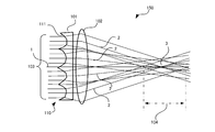
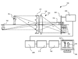
- FIG. 1 is a schematic diagram of a phase filter 101 and an imaging optical system 150 on which the phase filter 101 according to the first embodiment is mounted.
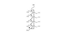
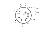
- FIG. 2 is a plan view showing the structure of the phase filter 101 according to the first embodiment.
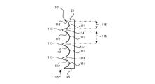
- the phase filter 101 has a disk-like outer shape and a rotationally symmetric shape with the optical axis 1 as the center. Further, in this phase filter 101, a plurality of rows of grooves having a parabolic cross section, that is, concave surfaces 112, are concentrically centered on the optical axis 1 described above at substantially equal intervals.
- the concave surface 112 formed concentrically around the optical axis 1 in this manner is referred to as an annular zone 111, and the annular zone 111 and the like are collectively referred to as an annular zone structure 110.
- the example of the phase filter 101 shown in FIGS. 1 to 3 has an annular structure 110 composed of two rows of annular zones 111.
- the annular zone 111 is a concave surface that acts as a concave lens in the radial direction of the pupil plane with respect to the light incident on the annular zone 111. Note that the width of the annular zone 111 in the phase filter 101 shown here is equal between the annular zones.
- the imaging lens 102 is arranged so that the phase filter 101 and the optical axis 1 are in common.
- the imaging lens 102 is a lens that can form an image of the object space at a predetermined position on the optical axis 1 when the phase filter 101 is not provided.
- the imaging optical system 150 By forming the imaging optical system 150 with a configuration in which the imaging lens 102 is combined with the phase filter 101, the light beam 103 (incident light beam) incident on the phase filter 101 is refracted by the concave surface 112 described above, and is locally divergent light. It becomes.
- the curvature of the concave surface 112 in the phase filter 101 is set so that the diverging light becomes a locally substantially parallel light beam (on the paper surface) by the imaging lens 102.
- substantially parallel locally refers to a state in which the light rays of the concave surfaces 112 that have passed through the concave surfaces 112 are substantially parallel after passing through the imaging lens 102.
- the propagation direction of the local substantially parallel light beam is directed to the original focal position 3 along the refraction direction of the light beam 2 passing through the center of the annular zone 111.
- a virtual tangential plane with respect to the concave surface 112 (parabolic cross section) at the center of the annular zone 111 is perpendicular to the optical axis 1 of the imaging lens 102, and rays passing therethrough are not refracted by the phase filter 101.
- the substantially parallel light fluxes from the plurality of annular zones 111 overlap in the range 104 in the optical axis direction in the vicinity of the focal point 3.
- the light beam diverging and refracted by the imaging lens 102 from each annular zone 111 has been described as a substantially parallel light beam.
- the propagation form is a light beam propagating along the side surface of the cone.
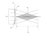
- Such a light beam is a light beam similar to a refracted light beam by the axicon 201 shown in FIG.
- the axicon 201 is a conical lens in which a first surface is a flat bottom surface 202 and a second surface is a cone, and is also called an axicon prism.
- FIG. 4 schematically shows the relationship between the side cross section of the axicon 201, the optical axis 1, and the incident parallel light beam 203.
- the parallel light beam 203 incident from the bottom surface 202 of the axicon 201 is refracted by the inclined side surface 204 of the axicon 201 and is uniformly converged in an optical path along a virtual conical surface.
- a region 205 is formed such that two cones are bonded together with their bottom surfaces facing each other (see FIG. 4 is colored with the intention of clearly indicating the corresponding area).
- a non-diffracted beam is formed in a range 202 in the optical axis direction. 1 corresponds to the fact that a plurality of light beams of the axicon 201 illustrated in FIG. 4 overlap at different angles, and a plurality of non-diffracted beams overlap. Smoothing of the image distribution in the focal direction is achieved.
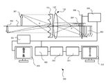
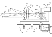
- the configuration of the imaging optical system 150 using the phase filter 101 and the imaging system 300 that performs image processing on an image captured by the imaging optical system 150 will be described with reference to FIG.
- the object 301 exists at a relatively short distance from the imaging optical system 150 and the object 302 exists at a far distance.
- the imaging system 300 has a configuration in which the image sensor 305 is disposed at a position where the images 303 and 304 and the like overlap in the optical axis direction.
- the imaging system 300 converts the output signal from the image sensor 305 described above into an appropriate still image or video image format and outputs it as an image signal while maintaining the highest resolution information that can be output by the image sensor 305.
- An image signal output circuit 306 is provided.
- the imaging system 300 includes a monitor output generation circuit 307 that receives the image signal output from the image signal output circuit 306, converts the image signal into a format that can be displayed on the display, and outputs the image signal on the monitor display 308. As schematically shown in FIG. 5, images 303 and 304 in which the near object 301 and the distant object 302 are uniformly blurred are obtained as images displayed on the monitor display 308. However, since such monitor output processing is not essential for the imaging system 300, there is no problem even if the monitor display 308 and the monitor output generation circuit 307 are not included.
- the imaging system 300 also includes a deconvolution preprocessing circuit 309 and a deconvolution filter circuit 310.
- the output signal from the image signal output circuit 306 described above is branched and input to the deconvolution preprocessing circuit 309.
- the deconvolution preprocessing circuit 309 converts the digital image data format suitable for the filter operation in the deconvolution filter circuit 310.
- the output signal of the deconvolution preprocessing circuit 309 is filtered by the deconvolution filter circuit 310 and input to the second monitor output generation circuit 311.
- the second monitor output generation circuit 311 converts the input signal from the deconvolution filter circuit 310 into an arbitrary general still image or moving image format, and outputs and displays it as an output signal on the second monitor display 312.
- FIG. 6 is a schematic diagram for formulating the shape of the parabolic cross section (that is, the concave surface 112) in the phase filter 101.
- the horizontal axis indicates the radius coordinate of the pupil plane
- the vertical axis indicates the shape of the phase filter 101. Further, only one period is displayed here, and even is shown when the optical axis position with a radius of 0 has a sharp apex, and odd when the bottom of the parabola is on the optical axis.
- the depth of the parabolic section is d. This shape is repeated in the radial direction with a period p.
- Such a shape is If we expand the Fourier series like It can be expressed as Where the period p is It is.
- r n is the radius of the n-th annular zone 111, which corresponds to a pupil radius of the imaging optical system 150.
- Such an annular structure 110 is an annular structure in which the width and the phase difference of the annular zone 111 are all equal. It is assumed that the phase filter 101 is disposed on the pupil plane of the imaging optical system 150. In the actual imaging optical system 150, this may be arranged at the stop position.
- the sectional shape of the annular zone 111 is assumed to be a parabolic sectional shape, but this is not necessarily limited to the sectional shape being described by a quadratic function with respect to local radial coordinates. Not what you want.
- a circular or elliptical cross section may be used.
- the quadratic expansion term with respect to the radius is dominant in the vicinity of the apex of the cross section of the annular zone 111, so that it is described as a parabolic cross section.
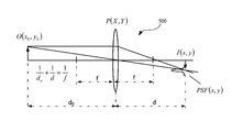
- FIG. 7 there is an object given by a light intensity distribution O (x0, y0) at a distance d 0 by an imaging optical system 500 having a focal length f, and the optical image intensity distribution I (x, y) is Assume that an image is formed at a position of distance d based on the imaging formula in the figure.
- the image I (x, y) is formed by superposition of the wave optical point image distribution PSF (x, y) of the point light sources. is there.
- the spatial frequency spectrum of the image plane light intensity distribution is the product of the spatial frequency spectrum of the object plane and the spatial frequency spectrum of the point image distribution.
- the spatial frequency spectrum of the point spread is called the optical transfer function OTF, It is expressed by the autocorrelation calculation of the pupil function.
- OTF optical transfer function
- the image plane intensity distribution is On the contrary, if the image plane intensity distribution and OTF are known, the geometrical mapping of the light intensity distribution on the object plane on the image plane, that is, the ideal optical image, It can be expressed as This operation is called deconvolution. Deconvolution requires that the OTF does not become zero, as can be seen from the form of the equation. Even when images with different object distances are mixed in the image plane, an ideal optical image can be uniformly obtained by deconvolution if the point image distribution is the same regardless of the defocus.
- FIG. 8 shows a comparative example of the processing result of the captured image depending on the presence or absence of the phase filter 101 of the first embodiment.
- the simulation conditions in the simulation result 510 shown in FIG. 8 are: focal length 50 mm, effective diameter 15.625 mm, F number 3.2, wavelength 0.5 ⁇ m, object distance 710 mm, sensor size 15 mm, annular zone pitch 0.8 mm, The phase difference is 4.24 ⁇ , the odd case, the approximate order is 8th, and the image size is 1024 ⁇ 1024.
- the OTF used for deconvolution uses the average of OTF with 0 mm defocus and 1 mm OTF.
- the gradation of an image acquired by a camera that is, an imaging optical system or an imaging system
- the original image is a spoke-like monochrome image with 0 and maximum brightness
- the upper stage is a normal acquired image without the phase filter 101
- the middle stage is a camera acquired image when the phase filter 101 of the first embodiment is applied
- the lower stage is a deconvolution. It is a result image.
- the column direction is ⁇ 2, ⁇ 1, 0, 1, 2 mm from the left in terms of the defocus amount of the sensor surface. In this case, minus means that the sensor is close to the lens, and plus means that the sensor is far from the lens.
- the calculation result of the evaluation index value of the image is shown by a white number on the lower left of the image after the deconvolution processing without the phase filter 101.
- the image evaluation index is a numerical value called PSNR (Peak Signal to Noise Ratio), Defined by Here, Max is maximum luminance, m and n are horizontal and vertical image sizes, I (i, j) is an evaluation image, and O (i, j) is an original image. From this result, it can be seen that although it does not reach a normal image without defocus, there is no noticeable image degradation within a defocus range of ⁇ 2 mm, and the depth of focus is increased.
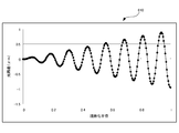
- FIG. 9 shows the wavefront aberration of the pupil plane, that is, the phase distribution 520 by the phase filter 101 of the first embodiment. However, here, the defocus wavefront aberration is not included. It can be seen that each annular zone 111 has a parabolic cross-sectional phase shift.
- the horizontal axis represents the pixel position of the image
- the vertical axis represents the luminance
- the calculation area range is 0.938 mm.
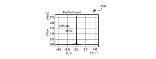
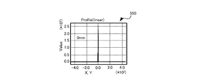
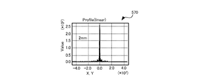
- the graph shows the calculation results when the defocus amount is set to -2, -1, 0, 1, 2 mm from the upper left to the lower right.
- FIG. 15 is a plan view showing the structure of the phase filter 101 of the second embodiment
- FIG. 16 is a side sectional view showing the structure of the phase filter 101 of the second embodiment.
- the phase filter 101 has an annular ring 111 including a concave surface 112 that acts as a concave lens in the radial direction of the pupil plane with respect to an incident light beam, and an annular zone 114 that includes a convex surface 113 that acts as a convex lens. It has a band structure 110.
- FIG. 17 shows the wavefront aberration of the pupil plane, that is, the phase distribution 580, by the phase filter 101 having such a structure.
- the horizontal axis represents the normalized radius of the pupil plane
- the vertical axis represents the optical path difference ( ⁇ m).
- ⁇ m the optical path difference
- the refractive action of the annular zone 111 does not act on the light flux incident between the annular zones 111 (the annular zone acting as a concave lens) in the phase filter 101 of the first embodiment, that is, the steep and sharp convex portion.
- the incident light is incident on a region near the annular zone 114 on the concave surface 112 of the annular zone 111.
- the light beam to be reflected can be refracted as desired by the convex lens action of the annular zone 114, and its phase distribution 580 does not show a sharp peak as in the phase distribution 520 (FIG. 9) of the first embodiment, and is smooth. Shape.
- the phase filter 101 having such a structure, the steep and sharp convex portions as described above do not exist between the annular zones, so that occurrence of chipping in the phase filter 101 can be suppressed.
- the concave lens zone 111 and the convex lens zone 114 have been described for the sake of convenience. However, in practice, the zone width is defined with a region where both are integrated as one zone.
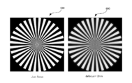
- FIG. 18 shows an image after deconvolution when the phase filter 101 in the second embodiment is used.
- conditions other than the phase filter are the same as those in the first embodiment.
- the left image 590 is a case where there is no defocus (Just focus), and the right image 600 is a case where the defocus is 2 mm.
- the image quality is slightly inferior to that of the first embodiment, it can be seen that there is an effect of expanding the depth of focus similar to that of the first embodiment.
- the depth of the concave surface 112 is the same in the vicinity of the optical axis 1 and in the peripheral portion 25, The closer to 1, the greater the change in the point where the light beam intersects the optical axis 1.
- This can be considered to be equivalent to the fact that the contribution to the expansion of the depth of focus is larger as it is closer to the optical axis 1 and is smaller as the peripheral portion 25 is smaller. Therefore, an example of the phase filter 101 in which the depth of the concave surface 112 becomes deeper as the peripheral edge 25 is described below. Note that the depth of the concave surface 112 in the annular zone 111 increases from the optical axis 1 toward the peripheral edge 25, but the annular zone width is constant in all annular zones.
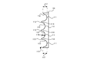
- FIG. 19 is a plan view showing the structure of the phase filter of the third embodiment
- FIG. 20 is a side sectional view showing the structure of the phase filter of the third embodiment.
- the depth 117 of the concave surface 112 in the outermost annular zone 111 closest to the peripheral portion 25 is deeper than the depth 118 of the concave surface 112 in the inner peripheral annular zone 111.
- the phase filter 101 has an annular ring 111 including a concave surface 112 that acts as a concave lens in the radial direction of the pupil plane with respect to an incident light beam, and an annular zone 114 that includes a convex surface 113 that acts as a convex lens. It has a band structure 110.
- FIG. 21 shows the wavefront aberration of the pupil plane by the phase filter 101 having such a structure, that is, the phase distribution 610.
- the change in the optical path difference increases as the depth of the concave surface 112 of the annular zone 111 in the phase filter 101 increases, and the amount of change in the phase shift also increases.
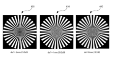
- FIG. 22 shows an image after deconvolution when the phase filter 101 in the third embodiment is used.
- conditions other than the phase filter are the same as those in the first embodiment.
- the image 620 on the left side of the page is a case where the focus shift is ⁇ 2 mm
- the center image 630 is a focus shift ⁇ 1 mm
- the right image 640 is a case where the focus shift is 0 mm.
- the dB value shown below each image is PSNR (Peak Signal-to-Noise Ratio). It can be seen that almost the same image quality as in the first embodiment is obtained.
- PSNR Peak Signal-to-Noise Ratio
- the phase filter 101 is a technique for expanding the effective depth of focus of the imaging optical system 150, and various application uses are conceivable.
- An example of an apparatus using the phase filter 101 will be described below in accordance with the application application.
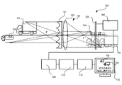
- FIG. 23 is a diagram illustrating a configuration example of the vehicle travel support apparatus 700 according to the second embodiment
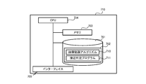
- FIG. 24 is a diagram illustrating a hardware configuration example of the information processing apparatus 710 included in the vehicle travel support apparatus 700 according to the second embodiment. is there.
- an apparatus that incorporates the phase filter 101 into an in-vehicle camera to photograph an obstacle around the vehicle and detects an obstacle to prevent a collision based on an image captured by the in-vehicle camera, that is, a vehicle travel support apparatus 700 can be assumed. .
- the vehicle travel support device 700 includes an image sensor 305, an image signal output circuit 306, a deconvolution preprocessing circuit 309, and a deconvolution filter circuit 310.
- the information processing device 710 is included. Further, the processing result in the information processing device 710 is displayed on the monitor display of the car navigation device 730 provided in the vehicle.
- the reflected light of other vehicles 701 and 702 existing around the vehicle on which the vehicle driving support device 700 is mounted enters the imaging lens 102 via the phase filter 101 in the imaging optical system 150.
- images 703 and 704 with uniform blurring in the direction of the optical axis 1 are formed. Therefore, in the vehicle travel support device 700, the image sensor 305 obtains sensing data of the images 703 and 704 and provides them to the image signal output circuit 306.
- the deconvolution preprocessing circuit 309 receives the image signal output from the image signal output circuit 306 and converts it into a digital image data format suitable for the filter operation in the deconvolution filter circuit 310.
- the output signal of the deconvolution preprocessing circuit 309 is filtered by the deconvolution filter circuit 310 and is input to the information processing device 710.
- the car navigation device 730 displays an image focused on the vehicle 702 and outputs sound such as a warning notification in response thereto.
- the hardware configuration of the information processing apparatus 710 included in the vehicle travel support apparatus 700 is as follows.
- the information processing device 710 reads into the memory 703 a storage device 701 configured with an appropriate non-volatile storage device such as a hard disk drive, a memory 703 configured with a volatile storage device such as a RAM, and a program 702 held in the storage device 701.
- a central processing unit (CPU) 704 for performing overall control of the apparatus itself and performing various determinations, computations and control processing, and 705 (display, keyboard, mouse, etc.) for receiving user input and outputting results.
- the program 702 at least an image recognition algorithm 710 for implementing functions necessary for the vehicle travel support apparatus 700 and an approach determination program 711 are stored. The processing of the program 702 will be described later.
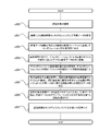
- the imaging optical system 150 captures the other vehicles 701 and 702, which are objects around the vehicle (s100), and the image sensor 305 senses the images 703 and 704 obtained by the imaging to acquire image data. (S101).
- the image sensor 305 provides the above-described image data to the image signal output circuit 306 as an image signal, and the image signal output circuit 306 maintains an appropriate still image or information while maintaining the highest resolution information that can be output by the image sensor 305.
- the image is converted into a moving image format and output to the deconvolution preprocessing circuit 309 as an image signal (s102).
- the deconvolution preprocessing circuit 309 receives the image signal output from the image signal output circuit 306 and converts it into a digital image data format suitable for the filter operation in the deconvolution filter circuit 310 (s103).
- the output signal of the deconvolution preprocessing circuit 309 is filtered by the deconvolution filter circuit 310 and input to the information processing apparatus 710 (s104).
- the information processing device 710 acquires the output data of the deconvolution filter circuit 310, that is, the depth-of-focus enlarged image, and applies the image recognition algorithm 710 for vehicle recognition to the depth-of-focus enlarged image, from the own vehicle.
- a plurality of objects such as other vehicles 701 and 702 that exist at different distances and are within a certain distance from the host vehicle are simultaneously detected (s105).
- the image recognition algorithm 710 for example, performs image processing such as specifying and highlighting a shape or size region (corresponding to the vehicle shape) of a predetermined color set of pixels for pixels constituting the original image. The algorithm to perform.
- the information processing device 710 causes the car navigation device 730 to display the images 703 and 704 of the other vehicles 701 and 702 detected in step s105, and displays a notification message warning that the other vehicles 701 and 702 are approaching.
- the car navigation device 730 displays or outputs the sound (s106). According to such a vehicle travel support device 700, it is possible to simultaneously detect an obstacle at a position close to the host vehicle and an obstacle at a position far away from the host vehicle, thereby improving safety during vehicle travel.
- FIG. 26 is a diagram illustrating a configuration example of the monitoring device 750 according to the third embodiment
- FIG. 27 is a diagram illustrating a hardware configuration example of the information processing device 760 included in the monitoring device 750 according to the third embodiment.
- the monitoring device 750 includes an image sensor 305, an image signal output circuit 306, a deconvolution preprocessing circuit 309, and a deconvolution filter circuit 310.
- a processing unit 760 is included. Further, the processing result in the information processing device 760 is displayed on the monitor display 780.
- the reflected light of the persons 751 and 752 existing in the monitoring target region spreading around the monitoring device 750 is incident on the imaging lens 102 via the phase filter 101 in the imaging optical system 150, and the direction of the optical axis 1. Images 753 and 754 with uniform blurring are formed. Therefore, in the monitoring device 750, the image sensor 305 obtains sensing data of the images 753 and 754 and provides this to the image signal output circuit 306.
- the deconvolution preprocessing circuit 309 receives the image signal output from the image signal output circuit 306 and converts it into a digital image data format suitable for the filter operation in the deconvolution filter circuit 310.
- the output signal of the deconvolution preprocessing circuit 309 is filtered by the deconvolution filter circuit 310 and input to the information processing device 760, and after a predetermined process, the person 752 far from the close person 751 described above.
- the monitor display 780 displays a focused image and outputs a warning notification or the like accordingly.
- the hardware configuration of the information processing device 760 included in such a monitoring device 750 is as follows.
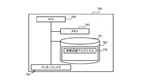
- the monitoring device 750 includes a storage device 761 configured by an appropriate non-volatile storage device such as a hard disk drive, a memory 763 configured by a volatile storage device such as a RAM, and reads a program 762 held in the storage device 761 to the memory 763.
- a CPU 764 that performs overall control of the apparatus itself and performs various determinations, calculations, and control processes, and 765 (display, keyboard, mouse, etc.) that accepts user input and outputs results.
- the program 762 stores at least an image recognition algorithm 770 for implementing functions necessary for the monitoring device 750. The processing of the program 702 will be described later.
- the imaging optical system 150 images the persons 751 and 752 located in the monitoring target area (s200), and the image sensor 305 senses images 753 and 754 obtained by the imaging to acquire image data (s201). ).
- the image sensor 305 provides the above-described image data to the image signal output circuit 306 as an image signal, and the image signal output circuit 306 maintains an appropriate still image or information while maintaining the highest resolution information that can be output by the image sensor 305.
- the image is converted into a moving image format and output to the deconvolution preprocessing circuit 309 as an image signal (s202).
- the deconvolution preprocessing circuit 309 receives the image signal output from the image signal output circuit 306 and converts it into a digital image data format suitable for the filter operation in the deconvolution filter circuit 310 (s203).
- the output signal of the deconvolution preprocessing circuit 309 is filtered by the deconvolution filter circuit 310 and input to the information processing apparatus 760 (s204).
- the information processing device 760 acquires the output data of the deconvolution filter circuit 310, that is, the depth of focus enlarged image, applies the image recognition algorithm 770 for person recognition to the depth of focus enlarged image, and monitors the monitoring device 750. And a plurality of persons 751 and 752 within a certain distance from the monitoring device 750, that is, in the monitoring target area, are simultaneously detected (s205).
- the image recognition algorithm 770 specifies, for example, a pixel set shape and size region (corresponding to a person's outer shape) of a predetermined color for pixels constituting the original image, and highlights the image processing. It becomes an algorithm to do.
- the information processing apparatus 760 displays the images 753 and 754 of the persons 751 and 752 detected in step s205 on the monitor display 780, and notifies the user that these persons 751 and 752 have entered the monitoring target area. Is displayed on the monitor display 780 or output as a sound (s206). According to such a monitoring apparatus 750, the recognition rate of a suspicious person or a criminal who has entered or is in the monitoring target area is improved regardless of the location distance from the imaging optical system.
- FIG. 29 is a diagram illustrating a configuration example of an authentication device according to the fourth embodiment
- FIG. 30 is a diagram illustrating a hardware configuration example of an information processing device included in the authentication device according to the fourth embodiment.
- the authentication apparatus 800 includes an image sensor 305, an image signal output circuit 306, a deconvolution preprocessing circuit 309, and a deconvolution filter circuit 310.
- a processing device 810 is included.
- the processing result in the information processing apparatus 810 is displayed on the monitor display 830.
- the reflected light of the fingers 801 and 802 that are to be authenticated by the authentication apparatus 800 (eg, fingers, palms, wrists, pupils serving as iris authentication parts, etc.)
- the light enters the imaging lens 102 via the phase filter 101 in the optical system 150, and forms images 803 and 804 with uniform blurring in the direction of the optical axis 1. Therefore, in the authentication apparatus 800, the image sensor 305 obtains sensing data of the images 803 and 804 and provides this to the image signal output circuit 306.
- the deconvolution preprocessing circuit 309 receives the image signal output from the image signal output circuit 306 and converts it into a digital image data format suitable for the filter operation in the deconvolution filter circuit 310.
- the output signal of the deconvolution preprocessing circuit 309 is filtered by the deconvolution filter circuit 310 and input to the information processing device 810. After a predetermined process, the shooting distance from the imaging optical system 150 is short.
- the monitor display 830 displays an image focused on the finger 801 at the occasion where the image is taken or the finger 802 at the time when the shooting distance is long, and displays the authentication processing result or outputs the sound accordingly. .
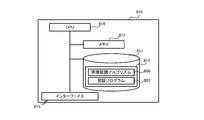
- the hardware configuration of the information processing apparatus 810 included in the authentication apparatus 800 is as follows.
- the information processing device 810 reads, to the memory 813, a storage device 811 configured with an appropriate nonvolatile storage device such as a hard disk drive, a memory 813 configured with a volatile storage device such as a RAM, and a program 812 held in the storage device 811.
- a CPU 814 for performing overall control of the apparatus itself and performing various determinations, computations and control processes, and 815 (display, keyboard, mouse, etc.) for receiving user input and outputting results.
- the program 812 stores at least an image recognition algorithm 880 for implementing a function necessary for the authentication apparatus 800 and an authentication program 881. The processing of the program 812 will be described later.
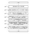
- the imaging optical system 150 in the authentication apparatus 800 images the authentication objects 801 and 802 (s300), and the image sensor 305 senses images 803 and 804 obtained by the imaging to acquire image data (s301).
- the image sensor 305 provides the above-described image data to the image signal output circuit 306 as an image signal, and the image signal output circuit 306 maintains an appropriate still image or information while maintaining the highest resolution information that can be output by the image sensor 305. It is converted into a moving image format and output to the deconvolution preprocessing circuit 309 as an image signal (s302).
- the deconvolution preprocessing circuit 309 receives the image signal output from the image signal output circuit 306 and converts it into a digital image data format suitable for the filter operation in the deconvolution filter circuit 310 (s303).
- the output signal of the deconvolution preprocessing circuit 309 is filtered by the deconvolution filter circuit 310 and input to the information processing apparatus 810 (s304).
- the information processing apparatus 810 acquires the output data of the deconvolution filter circuit 310, that is, the depth-of-focus enlarged image, and applies the image recognition algorithm 770 for recognition object recognition to the depth-of-focus enlarged image to obtain an authentication opportunity.
- the authentication data is image data corresponding to images 803 and 804 such as fingerprints, veins, and irises.
- the image recognition algorithm 770 identifies and highlights a pixel set shape and size region (corresponding to the shape of a fingerprint, vein, iris, etc.) of a predetermined color for pixels constituting the original image. This is an algorithm for performing image processing such as.
- the information processing device 810 inputs the image data of the authentication targets 801 and 802 obtained in step s305 to the authentication program 881, extracts the feature data by the authentication program 881, and extracts the feature data and a predetermined template (authentication target).
- a general authentication process is performed by executing each process of matching with authentication standard data prepared in advance for each person (s306).
- the information processing apparatus 810 displays or outputs the authentication result obtained in step s306 on the monitor display 830 (s307). According to such an authentication apparatus 800, even if there is a situation where the distance of the authentication target (human fingerprint, vein, iris, etc.) to the imaging optical system 150 changes every time authentication is performed, such a variation in distance is appropriately absorbed. As a result, the accuracy of authentication can be improved.
- the distance of the authentication target human fingerprint, vein, iris, etc.
- FIG. 32 is a diagram illustrating a configuration example of the medical device 850 according to the fifth embodiment
- FIG. 33 is a diagram illustrating a hardware configuration example of the information processing device 860 included in the medical device 850 according to the fifth embodiment.
- the medical device 850 includes an image sensor 305, an image signal output circuit 306, a deconvolution preprocessing circuit 309, and a deconvolution filter circuit 310.
- a processing unit 860 is included. Further, the processing result in the information processing device 860 is displayed on the monitor display 880.
- the reflected light of the affected areas 851 and 852 that become medical treatment target areas (eg, medical treatment, organs for medical examination) in the medical device 850 passes through the phase filter 101 in the imaging optical system 150 to the imaging lens 102.
- Incident light forms images 853 and 854 with uniform blurring in the direction of the optical axis 1. Therefore, in the medical device 850, the image sensor 305 obtains sensing data of the images 853 and 854 and provides this to the image signal output circuit 306.
- the deconvolution preprocessing circuit 309 receives the image signal output from the image signal output circuit 306 and converts it into a digital image data format suitable for the filter operation in the deconvolution filter circuit 310.
- the output signal of the deconvolution preprocessing circuit 309 is filtered by the deconvolution filter circuit 310 and input to the information processing device 860, and after a predetermined process, the affected part 851 that is close to the imaging optical system 150.
- the monitor display 880 displays an image focused on the affected area 852 which is far away.
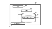
- the hardware configuration of the information processing device 860 included in the medical device 850 is as follows.
- the information processing device 860 reads, to the memory 863, a storage device 861 configured with an appropriate nonvolatile storage device such as a hard disk drive, a memory 863 configured with a volatile storage device such as a RAM, and a program 862 held in the storage device 861.
- a CPU 864 that performs overall control of the apparatus itself and performs various determinations, calculations, and control processing, and 865 (display, keyboard, mouse, etc.) that accepts user input and outputs results.
- the program 862 stores at least an image recognition algorithm 870 for implementing functions necessary for the medical device 850. The processing of the program 862 will be described later.
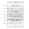
- the imaging optical system 150 in the medical device 850 images the affected areas 851 and 852 in the medical treatment target area (s400), and the image sensor 305 senses images 853 and 854 obtained by the imaging to acquire image data (s401). .
- the image sensor 305 provides the above-described image data to the image signal output circuit 306 as an image signal, and the image signal output circuit 306 maintains an appropriate still image or information while maintaining the highest resolution information that can be output by the image sensor 305.
- the image is converted into a moving image format and output to the deconvolution preprocessing circuit 309 as an image signal (s402).
- the deconvolution preprocessing circuit 309 receives the image signal output from the image signal output circuit 306 and converts it into a digital image data format suitable for the filter operation in the deconvolution filter circuit 310 (s403).
- the output signal of the deconvolution preprocessing circuit 309 is filtered by the deconvolution filter circuit 310 and input to the information processing device 860 (s404).
- the information processing apparatus 860 acquires the output data of the deconvolution filter circuit 310, that is, the depth-of-focus enlarged image, and applies the image recognition algorithm 870 of the affected area to the depth-of-focus enlarged image to capture an image in the medical treatment target region.
- Image data of a plurality of affected areas 851 and 852 existing at different distances from the optical system 150 is obtained (s405).
- the image recognition algorithm 870 specifies, for example, a pixel set shape and size region (corresponding to the shape of the affected part) of a predetermined color for pixels constituting the original image, and performs image processing such as highlighting. It becomes an algorithm to do.
- the information processing apparatus 860 displays the image data of the affected parts 851 and 852 obtained in step s405 on the monitor display 880 (s406). According to such a medical device 850, the simultaneous visibility of the affected part in the medical staff is enhanced regardless of the distance of the affected part from the imaging optical system 150. This facilitates the design of an optical system in a medical camera and the like, and the number of required lenses can be reduced, leading to a reduction in manufacturing cost.
- the in-plane positional shift of the image point corresponding to the defocus is eliminated, and the phase filter of the present embodiment and the optical system using the phase filter And the imaging system can be used for the purpose of measuring the object position by the position of the point image.
- the optical aspheric surface serving as the phase filter has a rotationally symmetric shape
- the mold used for forming the optical aspherical surface also has a rotationally symmetric shape, so that a rotating lathe can be processed when the mold is manufactured. Therefore, it is possible to shorten the production time of the phase filter mold and to reduce the manufacturing cost.
- an annular structure in the phase filter by introducing an annular structure in the phase filter, a large uneven shape is unnecessary, that is, the unevenness of the element is reduced, and the shift of the phase shift amount with respect to the light having a field angle can be reduced.
- an optical system equivalent to configuring the axicon in a ring shape can be realized, and application to the imaging optical system is possible.
- the annular zone may have a concave surface that acts as a concave lens in the radial direction of the pupil plane with respect to the incident light flux.
- the optical aspheric surface serving as the phase filter has a rotationally symmetric shape in which the annular concave surfaces are arranged concentrically, and the mold used for the molding also has a rotationally symmetric shape. Is possible. Therefore, it is possible to shorten the production time of the phase filter mold and to reduce the manufacturing cost. Further, by introducing such an annular structure in the phase filter, a large uneven shape is not required, that is, the unevenness of the element is reduced, and the shift of the phase shift amount with respect to the light having a field angle can be reduced.
- the annular zone may alternately include a concave surface that acts as a concave lens and a convex surface that acts as a convex lens in the radial direction of the pupil plane with respect to the incident light flux.
- the wavefront aberration of the pupil plane due to the phase distribution that is, the sharp peak in the phase distribution is eliminated, and the phase distribution is smooth compared with the case where the annular structure is formed only by the annular zone acting as a concave lens. Therefore, occurrence of chipping can be suppressed by the manufactured phase filter.
- the width of the annular zone may be equal between the annular zones. According to this, since the zonal structure in the phase filter becomes simple, it is possible to shorten the manufacturing time and the manufacturing cost of the mold used for the molding.
- the phase difference applied by the annular zones may be equal between the annular zones. According to this, the same phase shift can be added between each annular zone in the phase filter.
- each annular zone may be narrowed from the optical axis toward the peripheral edge of the phase filter. According to this, the area contributed by each annular zone can be made uniform, and the influence of manufacturing variations can be reduced.
- the phase difference applied by the annular zone may be larger in the peripheral portion of the phase filter than in the vicinity of the optical axis. According to this, the contribution of the phase filter to the expansion of the depth of focus in each annular zone can be leveled regardless of the distance from the optical axis.
- 1, 5, 23, 26, 29, and 32 each have a structure in which a phase plate having a single-sided flat surface or a single-sided phase structure is inserted. Even if the phase structure is directly formed on the lens surface close to, the effect is the same, so the phase filter may be directly formed integrally on such a lens surface.
- a lens optical system to which the present invention is applied not only a lens having a fixed focal length but also a zoom lens optical system having a variable focal length can be applied. If a phase filter is disposed in the vicinity of the stop or the pupil plane, there is some change in the depth of focus expansion effect, but it is basically applicable. Along with an increase in the depth of field that can be photographed, the focus adjustment between the image and the sensor surface becomes easy, and the focus adjustment mechanism can be eliminated.
Landscapes
- Physics & Mathematics (AREA)
- Engineering & Computer Science (AREA)
- General Physics & Mathematics (AREA)
- Optics & Photonics (AREA)
- Multimedia (AREA)
- Signal Processing (AREA)
- Theoretical Computer Science (AREA)
- Computer Vision & Pattern Recognition (AREA)
- Computing Systems (AREA)
- Studio Devices (AREA)
- Lenses (AREA)
- Optical Elements Other Than Lenses (AREA)
- Blocking Light For Cameras (AREA)
- Image Processing (AREA)
Abstract
位相フィルタ101において、光軸に対して回転対称な輪帯構造を備え、各輪帯が入射光束を焦点面上で一様に拡大し相互にオーバーラップさせる略放物断面形状を有するものとする。
Description
本発明は、位相フィルタ、撮像光学系、及び撮像システムに関するものであり、具体的には、WFCの画像処理後の焦点深度拡大画像において、焦点ずれに応じた像点の面内位置ずれの発生を抑制可能とする技術に関する。
===参照による取り込み===
本出願は、2013年3月29日に出願された日本特許出願第2013-72388号の優先権を主張し、その内容を参照することにより、本出願に取り込む。
本出願は、2013年3月29日に出願された日本特許出願第2013-72388号の優先権を主張し、その内容を参照することにより、本出願に取り込む。
撮像カメラ光学系の瞳面において、瞳面内座標に対して3次関数で与えられる位相分布を与えることによって焦点ずれに対する点像のぼけを均一化し、均一なぼけをデコンボリューションと称される画像処理によって除去して光学系の被写界深度や焦点深度を拡大するWavefront Coding(以下WFCと略す)と呼ばれる技術が提案されている。
こうしたWFCに関する従来技術として、例えば、撮像カメラの光学系に3次位相関数を実現した位相フィルタによって、瞳孔関数を位相変調し、撮像された画像に対して画像処理を施すことによって光学系の焦点深度を拡大する技術(特許文献1参照)などが提案されている。また、光学的伝達関数(OTF)を変調させる位相フィルタとして、光軸に直交するx、y座標とするとき、それらの任意のべき乗の積で表される関数の級数によって3次関数を一般化した形の位相分布を与え、撮像された画像に対して画像処理を施すことによって光学系の焦点深度を拡大する技術(特許文献2参照)なども提案されている。一方、撮像光学系ではないが、アキシコンと呼ばれる円錐プリズムを用いて非回折ビームを生成し、レーザーの波長変換の高効率化を図る技術(特許文献3参照)なども提案されている。
上述の従来技術においては、瞳面内座標のx軸やy軸に対して3次関数またはそれと類似した関数によって位相フィルタの位相分布を与えている。このように、光軸に対して回転対称でない位相フィルタを用いて焦点ずれに対する点像の均一化を図る場合、焦点ずれ量によって点像の位置がずれるという問題がある。
たとえば3次関数では規格化瞳面座標x、yに対して、位相分布は係数αを用いて、

によって表される。ここに焦点ずれの波面収差が加わると、規格化瞳半径座標ρを用いて、
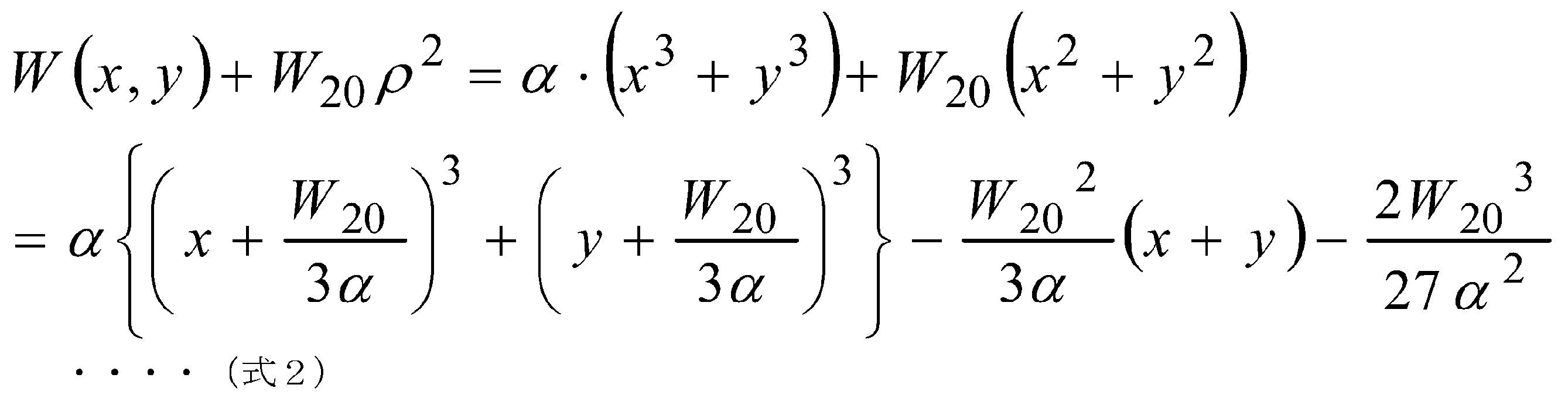
のように表される。ここでW20は焦点ずれ、すなわちデフォーカスの収差係数である。第1項は3次関数位相分布が瞳面内でx、y方向ともにW20/3αだけずれて加わることを意味している。これは、基本的には焦点面上では位相ずれに相当するため点像強度分布には影響しない。第2項はx、yの1次関数の位相分布であるため、いわゆる波面チルトに相当し、W20 2/3αに比例して焦点面上の像点位置がずれることを意味する。第3項は定数項のため点像強度分布に影響しない。したがって3次関数位相分布があると、焦点ずれの波面収差は点像分布の横ずれに変換されることになる。したがってこの横ずれだけを許容すれば焦点ずれがあっても点像分布が実質的に変化しないことになり、ぼけ方が焦点ずれによらず一様になる。これによってデコンボリューションが可能となる。これがWFCの原理である。しかしそのため焦点ずれによって点像のずれが生じるため、点像の位置によって物体の位置の計測を行うような用途では問題となる。
によって表される。ここに焦点ずれの波面収差が加わると、規格化瞳半径座標ρを用いて、
のように表される。ここでW20は焦点ずれ、すなわちデフォーカスの収差係数である。第1項は3次関数位相分布が瞳面内でx、y方向ともにW20/3αだけずれて加わることを意味している。これは、基本的には焦点面上では位相ずれに相当するため点像強度分布には影響しない。第2項はx、yの1次関数の位相分布であるため、いわゆる波面チルトに相当し、W20 2/3αに比例して焦点面上の像点位置がずれることを意味する。第3項は定数項のため点像強度分布に影響しない。したがって3次関数位相分布があると、焦点ずれの波面収差は点像分布の横ずれに変換されることになる。したがってこの横ずれだけを許容すれば焦点ずれがあっても点像分布が実質的に変化しないことになり、ぼけ方が焦点ずれによらず一様になる。これによってデコンボリューションが可能となる。これがWFCの原理である。しかしそのため焦点ずれによって点像のずれが生じるため、点像の位置によって物体の位置の計測を行うような用途では問題となる。
また、3次関数分布のような、光軸に対して回転対称でない位相分布を発生させる光学面は、基本的に同様の非球面光学面が必要である。非球面はバイトによる回転旋盤加工によって加工される金型により、プラスチック射出成形や、ガラスモールドプレス成形などが広く普及している。しかし旋盤加工は軸対称な形状が必須であり、3次関数非球面のような非軸対称な形状では、回転研削バイトによる2次元の数値制御加工が必要となり、加工コストや加工時間が増すという問題がある。
また、3次関数分布のような連続関数で記述される位相フィルタでは、少なくとも数十波長以上の凹凸形状が必要であり、画角のある光線が入射する場合に、位相シフト量が所望のシフト量からずれるという問題がある。
またアキシコンを用いる光学系では、アキシコンの底面に入射する平行ビームが屈折されオーバーラップする範囲で、レーザビームが細いビームに集光されたまま回折せずに伝播する。しかしこのレンズは平行ビームに対して用いられるもので、撮像カメラのようにたくさんの結像点を同時に得ることが必要な光学系に用いることはできない。
そこで本発明の目的は、WFCの画像処理後の焦点深度拡大画像において、焦点ずれに応じた像点の面内位置ずれの発生を抑制可能とする技術を提供することにある。
上記課題を解決する本発明の位相フィルタは、光軸に対して回転対称な輪帯構造を備え、各輪帯が入射光束を焦点面上で一様に拡大し相互にオーバーラップさせる略放物断面形状を有している。これによれば、WFCの画像処理後の焦点深度拡大画像において、焦点ずれに応じた像点の面内位置ずれの発生を抑制できる。
また、本発明の撮像光学系は、光軸に対して回転対称な輪帯構造を備え、各輪帯が入射光束を焦点面上で一様に拡大し相互にオーバーラップさせる略放物断面形状を有した位相フィルタを、結像光学系に搭載する。これによれば、WFCの画像処理後の焦点深度拡大画像において、焦点ずれに応じた像点の面内位置ずれの発生を抑制できることとなり、当該撮像光学系を、点像の位置によって物体位置の計測を行う用途に用いることが可能となる。
また、本発明の撮像光学系は、光軸に対して回転対称な輪帯構造を備え、各輪帯が入射光束を焦点面上で一様に拡大し相互にオーバーラップさせる略放物断面形状を有した位相フィルタを、結像光学系に搭載する。これによれば、WFCの画像処理後の焦点深度拡大画像において、焦点ずれに応じた像点の面内位置ずれの発生を抑制できることとなり、当該撮像光学系を、点像の位置によって物体位置の計測を行う用途に用いることが可能となる。
また、本発明の撮像システムは、光軸に対して回転対称な輪帯構造を備え、各輪帯が入射光束を焦点面上で一様に拡大し相互にオーバーラップさせる略放物断面形状を有した位相フィルタを、結像光学系に搭載した撮像光学系にて撮像された画像に対し、デコンボリューション画像処理を行い、焦点深度拡大画像を得る。これによれば、WFCの画像処理後の焦点深度拡大画像において、焦点ずれに応じた像点の面内位置ずれの発生を抑制できることとなり、当該撮像システムを、点像の位置によって物体位置の計測を行う用途に用いることが可能となる。
また、本発明の車両走行支援装置は、光軸に対して回転対称な輪帯構造を備え、各輪帯が入射光束を焦点面上で一様に拡大し相互にオーバーラップさせる略放物断面形状を有した位相フィルタを結像光学系に搭載した撮像光学系にて撮像した、車両周囲物体の画像に対し、デコンボリューション画像処理を行って焦点深度拡大画像を取得し、当該焦点深度拡大画像に所定の画像認識アルゴリズムを適用して、車両から一定距離内にあって互いに異なる距離に存在する複数物体を同時に検知する。これによれば、車両から近い位置にある障害物も遠い位置にある障害物も同時に検知することが可能となり、車両走行上の安全性向上の効果がある。
また、本発明の監視装置は、光軸に対して回転対称な輪帯構造を備え、各輪帯が入射光束を焦点面上で一様に拡大し相互にオーバーラップさせる略放物断面形状を有した位相フィルタを結像光学系に搭載した撮像光学系にて撮像した、監視対象領域の画像に対し、デコンボリューション画像処理を行って焦点深度拡大画像を取得し、当該焦点深度拡大画像に所定の画像認識アルゴリズムを適用して、監視対象領域において前記撮像光学系から異なる距離に存在する複数人物を同時に検知する。これによれば、撮像光学系からの所在距離によらず、監視対象領域に侵入した、あるいは所在する不審者や犯罪者等の認識率が向上する。
また、本発明の認証装置は、光軸に対して回転対称な輪帯構造を備え、各輪帯が入射光束を焦点面上で一様に拡大し相互にオーバーラップさせる略放物断面形状を有した位相フィルタを結像光学系に搭載した撮像光学系にて複数次撮像した、同一認証対象の各画像に対し、デコンボリューション画像処理を行って焦点深度拡大画像を取得し、当該焦点深度拡大画像に所定の画像認識アルゴリズムを適用して、前記撮像光学系からの撮影距離が異なる各画像から前記同一認証対象を認証する。これによれば、撮像光学系に対する認証対象(人の指紋、静脈、虹彩等)の距離が認証を行う毎に変化する状況があっても、そうした距離のばらつきを適宜吸収して、ひいては認証精度の向上が可能となる。
また、本発明の医療装置は、光軸に対して回転対称な輪帯構造を備え、各輪帯が入射光束を焦点面上で一様に拡大し相互にオーバーラップさせる略放物断面形状を有した位相フィルタを結像光学系に搭載した撮像光学系にて撮像した、人体における診療対象領域の画像に対し、デコンボリューション画像処理を行って焦点深度拡大画像を取得し、当該焦点深度拡大画像に所定の画像認識アルゴリズムを適用して、診療対象領域において前記撮像光学系から異なる距離に存在する複数部位の画像を同時に出力する。これによれば、撮像光学系からの患部の遠近によらず、医療従事者における患部の同時視認性が高まることとなる。このことは医療用カメラ等における光学系の設計を容易化し、レンズ必要枚数の削減等も可能となり、製造コスト削減にもつながる。
なお、上述の車両走行支援装置、監視装置、認証装置、および医療装置の、いずれの装置においても、レンズとセンサ面との調整精度が緩和され、製造コストの削減を図ることができる。
本発明によれば、WFCの画像処理後の焦点深度拡大画像において、焦点ずれに応じた像点の面内位置ずれの発生を抑制できる。
以下に本発明の実施形態について図面を用いて詳細に説明する。図1は第1実施形態における位相フィルタ101とそれを搭載した撮像光学系150の模式図であり、図2は第1実施形態における位相フィルタ101の構造を示す平面図、図3は同じく側断面図である。なお、図1にて示す撮像光学系150が含む、位相フィルタ101および結像レンズ102はいずれも側断面の形状を示したものとなっている。
図1~3にて示すように、位相フィルタ101は、外形が円盤状で光軸1を中心とした回転対称な形状となっている。また、この位相フィルタ101は、放物線状の断面形状を有する溝すなわち凹面112が、上述の光軸1を中心に同心円状に略等間隔で複数列形成されている。このように光軸1を中心に同心円状に形成された凹面112を輪帯111とし、輪帯111らを輪帯構造110と総称する。図1~3にて示す位相フィルタ101の例では、2列の輪帯111からなる輪帯構造110を有している。輪帯111は当該輪帯111に入射する光線に対して瞳面の半径方向に凹レンズとして作用する凹面となる。なお、ここで示す位相フィルタ101における輪帯111の幅は各輪帯間で等しいものとなっている。
撮像光学系150においては、上述の位相フィルタ101と光軸1を共通にするよう、結像レンズ102が配置されている。この結像レンズ102は位相フィルタ101が無い場合、物体空間の像を光軸1上の所定位置に結像させることができるレンズである。こうした結像レンズ102に位相フィルタ101を組み合わせた構成で撮像光学系150をなすことで、位相フィルタ101に入射する光線103(入射光束)は、上述した凹面112によって屈折され、局所的に発散光となる。この発散光が結像レンズ102によって(紙面上)局所的に略平行な光束となるよう、位相フィルタ101における凹面112の曲率は設定されている。局所的に略平行とは、各凹面112を通過した凹面112毎の光線が、結像レンズ102の通過後に略平行となっている状態を指す。
この局所的な略平行光束の伝播方向は輪帯111の中心を通る光線2の屈折方向に沿って元の焦点位置3に向かう。なぜなら輪帯111の中心での凹面112(放物断面)に対する仮想的な接平面は、結像レンズ102の光軸1に垂直であり、そこを通る光線は位相フィルタ101で屈折せずに結像レンズ102に入射するため、その光線は位相フィルタ101がない場合の焦点位置3を通ることが明らかであるからである。このように複数の輪帯111からの略平行光束が焦点3の近傍において光軸方向に範囲104でオーバーラップする。説明の便宜上、上記では各輪帯111からの、発散し結像レンズ102によって屈折された光束を、略平行光束と述べたが、実際には光軸1を中心に回転対称であるから、実際の伝播形態は円錐の側面に沿って伝播するような光束である。
このような光束は、図4に示すアキシコン201による屈折光線と同様の光束となる。アキシコン201は、第1面が平面たる底面202であり、第2面が円錐になっている円錐レンズ(conical lens)であり、アキシコンプリズムとも呼ばれている。図4では、こうしたアキシコン201の側断面と光軸1、入射する平行光束203の関係を模式的に示している。アキシコン201の底面202から入射する平行光束203は、傾斜するアキシコン201の側面204で屈折し、仮想的な円錐面に沿うような光路で一様に収束される。両側から角度を持って入射する光束203が、図中、ひし形状にオーバーラップする範囲202では、円錐を2つ、その底面を互いに対向させて貼り合わせたような領域205が形成される(図4では、該当領域を明示する意図で着色して示している)。この領域205内では光軸方向の範囲202において非回折ビームが形成される。上述した図1の位相フィルタ101における各輪帯111からの光束は、図4に例示するアキシコン201の光束が、異なる角度で複数オーバーラップすることに対応し、複数の非回折ビームが重なり合って点像分布の焦点方向への平滑化が達成される。
続いて、位相フィルタ101を用いた撮像光学系150と、当該撮像光学系150にて撮像される画像に対し画像処理を施す撮像システム300の構成について図5に基づき説明する。ここでは、撮像光学系150から比較的近い距離に物体301が存在し、遠い距離に物体302が存在している状況を想定する。
この場合、上述の物体301、物体302の反射光が、撮像光学系150における位相フィルタ101を介して結像レンズ102に入射し、光軸1の方向にぼけ方が均一(上述した点像分布の焦点方向への平滑化による)な像303、304を形成することになる。そこで撮像システム300においては、像303、304らが光軸方向にオーバーラップする位置に画像センサ305を配置した構成となっている。
また、撮像システム300は、上述の画像センサ305からの出力信号を、画像センサ305で出力可能な最高解像度の情報を保ったまま、適宜な静止画または動画の画像フォーマットに変換し画像信号として出力する画像信号出力回路306を備えている。また、撮像システム300は、画像信号出力回路306で出力した画像信号を受けて、これをディスプレイ出力可能なフォーマットに変換し、モニタディスプレイ308で出力させるモニタ出力生成回路307を備えている。モニタディスプレイ308で表示される画像として、図5にて模式的に示す通り、近い物体301も、遠い物体302も一様にぼけた画像303、304が得られる。ただし、撮像システム300として、こうしたモニタ出力処理は必須ではないため、モニタディスプレイ308、およびモニタ出力生成回路307を含まない構成としても問題ない。
また、撮像システム300は、デコンボリューション前処理回路309、およびデコンボリューションフィルタ回路310を備えている。撮像システム300においては、上述の画像信号出力回路306からの出力信号を分岐して、デコンボリューション前処理回路309に入力する。これにより、デコンボリューション前処理回路309において、デコンボリューションフィルタ回路310でのフィルタ演算に適したデジタル画像データ形式に変換することとなる。また、このデコンボリューション前処理回路309の出力信号は、デコンボリューションフィルタ回路310にてフィルタ処理を行って第2のモニタ出力生成回路311に入力される。第2のモニタ出力生成回路311は、デコンボリューションフィルタ回路310からの入力信号を任意の一般の静止画、または動画の画像フォーマットに変換し、出力信号として第2のモニタディスプレイ312で出力表示させる。第2のモニタディスプレイ312で出力表示を行う場合、上述した、近い物体301にも遠い物体302にも焦点のあった画像が出力される。このとき、位相フィルタ101を用いているため、第2のモニタディスプレイ312での出力画像においては、撮像光学系150からの距離によって該当物体の画像位置がずれるようなことはなく、物体301、302の本来の位置を反映した位置に画像が形成される。
続いて、上述した位相フィルタ101を採用した際の焦点深度拡大効果を確認するシミュレーションについて説明する。図6は、位相フィルタ101における放物断面(すなわち凹面112)の形状を定式化するための模式図である。この図では、横軸が瞳面の半径座標、縦軸が位相フィルタ101の形状を示している。また、ここで表示しているのは1周期だけであり、半径0の光軸位置に先鋭な頂点を持つ場合をeven、放物線の底が光軸上になる場合をoddと表示している。放物断面の深さはdである。この形状が半径方向に周期pで反復される。このような形状は、

のようにフーリエ級数展開すると、結局、
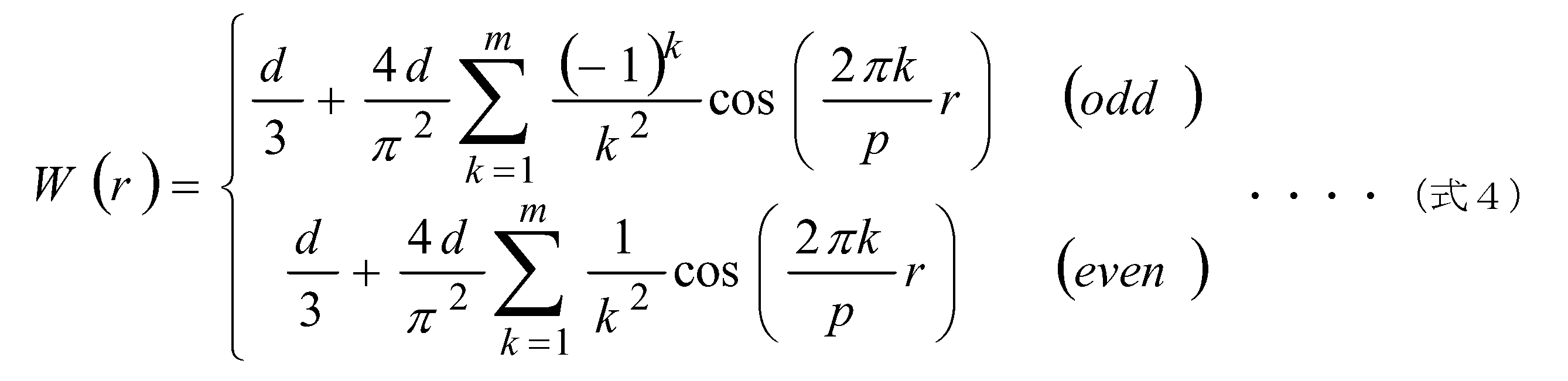
のように表せる。ここで周期pは、

である。ここでrnはn番目の輪帯111の半径であり、撮像光学系150の瞳半径に相当する。このような輪帯構造110は、輪帯111の幅と位相差がすべて等しい輪帯構造となる。なお、位相フィルタ101は撮像光学系150の瞳面に配置することを仮定する。これは実際の撮像光学系150では絞り位置に配置すればよいことになる。
のようにフーリエ級数展開すると、結局、
のように表せる。ここで周期pは、
である。ここでrnはn番目の輪帯111の半径であり、撮像光学系150の瞳半径に相当する。このような輪帯構造110は、輪帯111の幅と位相差がすべて等しい輪帯構造となる。なお、位相フィルタ101は撮像光学系150の瞳面に配置することを仮定する。これは実際の撮像光学系150では絞り位置に配置すればよいことになる。
上述したように、位相フィルタ101において輪帯111の断面形状は放物断面形状であるとしているが、これは必ずしも局所的な半径座標に対して2次関数で断面形状が記述されることに限定するものではない。例えば円形や楕円形の断面であってもよい。いずれも輪帯111の断面の頂点の近傍では半径に対する2次の展開項が支配的であることから放物断面と述べているものである。
次にデコンボリューション画像処理について説明する。図7に示すように焦点距離fの結像光学系500により、距離d0に光強度分布O(x0、y0)で与えられる物体があり、その光学像強度分布I(x、y)が、図中の結像公式に基づいて距離dの位置に結像されているとする。このとき、物体の光強度分布を点光源の集合と考えると、像I(x,y)を形成するのはその点光源の波動光学的な点像分布PSF(x、y)の重ね合わせである。この点像分布は結像光学系500の絞りの開口、すなわち瞳面の振幅透過率分布P(X,Y)としたとき、

で与えられる。ここでFは2次元フーリエ変換であり、

と表せる。フーリエ変換は一般によく知られているように、物理量の時間や空間分布を、その周波数スペクトルに変換する演算である。この点像分布を、物体面の光強度分布の幾何学的写像O(x、y)に対して重畳して積分することにより、像面の強度分布は、

のように表せる。ここで*はコンボリューション積分の演算を意味する。さらにこの像面強度分布にフーリエ変換を施すことにより、

のように像面光強度分布の空間周波数スペクトルが物体面の空間周波数スペクトルと点像分布の空間周波数スペクトルの積であることが導ける。点像分布の空間周波数スペクトルは光学伝達関数OTFと呼ばれ、

のように瞳関数の自己相関演算で表されている。上述の式9から像面強度分布は、

のように表せることから、逆に像面強度分布とOTFが既知であれば、像面上における物体面上光強度分布の幾何学的写像、すなわち理想光学像が、

のように表せる。この演算がデコンボリューションと呼ばれている。デコンボリューションは式の形からもわかるように、OTFがゼロにならないことが必要である。また像面内に異なる物体距離の像が混在する場合でも、それらの点像分布が焦点ずれによらず同一であれば、デコンボリューションで一様に理想光学像を得ることができる。
で与えられる。ここでFは2次元フーリエ変換であり、
と表せる。フーリエ変換は一般によく知られているように、物理量の時間や空間分布を、その周波数スペクトルに変換する演算である。この点像分布を、物体面の光強度分布の幾何学的写像O(x、y)に対して重畳して積分することにより、像面の強度分布は、
のように表せる。ここで*はコンボリューション積分の演算を意味する。さらにこの像面強度分布にフーリエ変換を施すことにより、
のように像面光強度分布の空間周波数スペクトルが物体面の空間周波数スペクトルと点像分布の空間周波数スペクトルの積であることが導ける。点像分布の空間周波数スペクトルは光学伝達関数OTFと呼ばれ、
のように瞳関数の自己相関演算で表されている。上述の式9から像面強度分布は、
のように表せることから、逆に像面強度分布とOTFが既知であれば、像面上における物体面上光強度分布の幾何学的写像、すなわち理想光学像が、
のように表せる。この演算がデコンボリューションと呼ばれている。デコンボリューションは式の形からもわかるように、OTFがゼロにならないことが必要である。また像面内に異なる物体距離の像が混在する場合でも、それらの点像分布が焦点ずれによらず同一であれば、デコンボリューションで一様に理想光学像を得ることができる。
図8に第1実施例の位相フィルタ101の有無による撮像画像の処理結果比較例を示す。図8にて示すシミュレーション結果510における、シミュレーション条件は、焦点距離50mm、有効径15.625mm、Fナンバー3.2、波長0.5μm、物体距離710mm、センササイズ15mm、輪帯ピッチ0.8mm、位相差4.24λ、Oddケース、近似次数8次、画像サイズ1024×1024である。デコンボリューションに用いたOTFはデフォーカス0mmと1mmのOTFの平均を用いている。カメラ(すなわち撮像光学系ないし撮像システム)で取得される画像の階調は12bitを仮定した。元画像は0と最大輝度のスポーク状のモノクロ画像であり、上段が位相フィルタ101なしの通常取得画像、中段が第1実施例の位相フィルタ101を適用した場合のカメラ取得画像、下段がデコンボリューション結果画像である。さらに列方向が、センサ面の焦点ずれ量で左から-2,-1,0,1,2mmである。この場合のマイナスは、センサがレンズに近く、プラスはセンサがレンズから遠いことを意味している。位相フィルタ101なしとデコンボリューション処理後の画像の左下には、白抜きの数字で、画像の評価指標値の計算結果を示している。画像の評価指標は、PSNR(Peak Signal to Noise Ratio)と呼ばれる数値であり、

で定義される。ここでMaxは最大輝度、m、nは横方向、縦方向の画像サイズ、I(i,j)は評価画像、O(i,j)は元画像である。この結果から、焦点ずれなしの通常画像には及ばないものの、±2mmの焦点ずれの範囲で目立った画像劣化もなく、焦点深度が拡大していることがわかる。図9に第1実施例の位相フィルタ101による瞳面の波面収差、すなわち位相分布520を示す。ただしここでは、焦点ずれの波面収差は含んでいない。各輪帯111で放物断面状の位相シフトが加わっていることがわかる。
で定義される。ここでMaxは最大輝度、m、nは横方向、縦方向の画像サイズ、I(i,j)は評価画像、O(i,j)は元画像である。この結果から、焦点ずれなしの通常画像には及ばないものの、±2mmの焦点ずれの範囲で目立った画像劣化もなく、焦点深度が拡大していることがわかる。図9に第1実施例の位相フィルタ101による瞳面の波面収差、すなわち位相分布520を示す。ただしここでは、焦点ずれの波面収差は含んでいない。各輪帯111で放物断面状の位相シフトが加わっていることがわかる。
また、図10~14にこのときの点像分布関数の計算結果を示す。各グラフにて、横軸は画像の画素位置、縦軸は輝度であり、計算領域範囲は0.938mmである。グラフは左上から右下にかけて焦点ずれ量を-2、-1、0、1、2mmとしたときの計算結果である。焦点ずれがない場合について集光スポットが絞られすぎている兆候があるが、その他は概ね同等のスポットサイズとなっていることがわかる。
上述した第1実施例では、輪帯幅(ピッチ)の等しい輪帯構造110の位相フィルタ101について説明したが、位相フィルタ101における輪帯111の幅が輪体間で等しい必要はない。図15は、第2実施例の位相フィルタ101の構造を示す平面図であり、図16は第2実施例の位相フィルタ101の構造を示す側断面図である。以下の第2実施例では、位相フィルタ101における輪帯111の幅が、光軸1から周縁部25に向けて狭くなっている例について説明する。図15、16に示す例では、周縁部25に一番近い、すなわち最外周の輪帯111の幅115は、その内周の輪帯111の幅116より狭くなっている。また、この位相フィルタ101は、入射光束に対して瞳面の半径方向に凹レンズとして作用する凹面112を含む輪帯111と、凸レンズとして作用する凸面113を含む輪帯114とを交互に備えた輪帯構造110を有している。
こうした構造の位相フィルタ101による瞳面の波面収差、すなわち位相分布580を図17に示す。この位相分布580において、横軸は瞳面の規格化半径であり、縦軸は光路差(μm)を示している。この位相分布580において、瞳面の規格化半径が大きいほど、すなわち位相フィルタ101の周縁部25ほど輪帯111の幅が狭くなっていることがわかる。このような構造を位相フィルタ101にて採用すると、各輪帯の寄与する面積を均一化することができ、製造ばらつきの影響を受けにくくなる。また第2実施例では位相差はすべての輪帯111で等しい輪帯構造である。
なお、第1実施例の位相フィルタ101における輪帯111(凹レンズとして作用する輪帯)間、すなわち急峻で鋭い凸状の部位に入射する光束には、輪帯111による屈折作用が作用しない。一方、上述したように凹レンズとして作用する輪帯111と凸レンズとして作用する輪帯114とが交互に配置された位相フィルタ101においては、輪帯111の凹面112のうち輪帯114直近の領域に入射する光束も、輪帯114の凸レンズ作用によって所望の屈折をさせることが可能となり、その位相分布580は第1実施例の位相分布520(図9)にあるような先鋭なピークを示さず、滑らかな形状となる。こうした構造の位相フィルタ101であれば、上述したような急峻で鋭い凸状の部位が輪帯間に存在しないため、当該位相フィルタ101でのチッピングの発生を抑えることができる。なお上記では便宜上、凹レンズの輪帯111と凸レンズの輪帯114とを説明したが、実際上は両方が一体となった領域を1つの輪帯として輪帯幅を定義している。
図18は上述の第2実施例における位相フィルタ101を用いた場合のデコンボリューション後の画像を示す。ここで位相フィルタ以外の条件は第1実施例の場合と同じである。左側の画像590は焦点ずれなし(Just focus)、右側の画像600は焦点ずれ2mmの場合である。第1実施例と比べ、やや画質が劣るが、第1実施例同様の焦点深度拡大効果があることがわかる。
ここで、位相フィルタ101の凹面112の傾斜が大きいほど屈折光線の傾斜角が大きくなるのに対して、光軸1の近傍でも周縁部25でも凹面112の深さが同じである場合、光軸1に近いほど光線が光軸1と交わる点の変化が大きくなる。これは焦点深度拡大に対する寄与が光軸1に近いほど大きく、周縁部25ほど小さくなることに相当すると考えることができる。そこで、以下に周縁部25ほど凹面112の深さが深くなる位相フィルタ101の例について説明する。なお、輪帯111における凹面112の深さは光軸1から周縁部25に向けて深くなるが、輪帯幅はすべての輪帯で一定であるものとする。
図19は第3実施例の位相フィルタの構造を示す平面図であり、図20は第3実施例の位相フィルタの構造を示す側断面図である。図19、20に示す例では、周縁部25に一番近い、すなわち最外周の輪帯111における凹面112の深さ117は、その内周の輪帯111における凹面112の深さ118より深くなっている。また、この位相フィルタ101は、入射光束に対して瞳面の半径方向に凹レンズとして作用する凹面112を含む輪帯111と、凸レンズとして作用する凸面113を含む輪帯114とを交互に備えた輪帯構造110を有している。
こうした構造の位相フィルタ101による瞳面の波面収差、すなわち位相分布610を図21に示す。この位相分布610に示すように、位相フィルタ101における輪帯111の凹面112の深さが深いことに応じて光路差の変化が大きくなり、位相シフトの変化量も大きくなる。
図22は第3実施例における位相フィルタ101を用いた場合のデコンボリューション後の画像を示す。ここで位相フィルタ以外の条件は第1実施例の場合と同じである。紙面左側の画像620は焦点ずれ-2mm、中央の画像630は焦点ずれ-1mm、右側の画像640は焦点ずれ0mmの場合である。また、各画像下に示したdB値はPSNR(Peak Signal-to-Noise Ratio)である。第1実施例とほぼ同等の画像品質が得られていることがわかる。
上述してきたように、位相フィルタ101は撮像光学系150の実効的な焦点深度を拡大させる技術となり、種々の適用用途が考えられる。以下にその適用用途に即して、位相フィルタ101を用いた装置例について説明する。
図23は第2実施形態における車両走行支援装置700の構成例を示す図であり、図24は第2実施形態における車両走行支援装置700が備える情報処理装置710のハードウェア構成例を示す図である。たとえば、位相フィルタ101を車載カメラに組み込んで車両周囲の障害物を撮影し、この車載カメラによる撮像画像に基づいて衝突防止のために障害物検知を行う装置、すなわち車両走行支援装置700が想定できる。
この車両走行支援装置700は、第1実施形態で示した撮像システム300と同様に、画像センサ305、画像信号出力回路306、デコンボリューション前処理回路309、およびデコンボリューションフィルタ回路310を備えている他、情報処理装置710を含んでいる。また、情報処理装置710での処理結果は車両が備えるカーナビゲーション装置730のモニタディスプレイにて表示されることとなる。
この場合、当該車両走行支援装置700を搭載した車両の周囲、例えば車両前方に存在する他車両701、702の反射光が、撮像光学系150における位相フィルタ101を介して結像レンズ102に入射し、光軸1の方向にぼけ方が均一な像703、704を形成することになる。そこで車両走行支援装置700においては、画像センサ305が像703、704らのセンシングデータを得て、これを画像信号出力回路306に提供する。また、デコンボリューション前処理回路309が画像信号出力回路306の出力たる画像信号を受けて、デコンボリューションフィルタ回路310でのフィルタ演算に適したデジタル画像データ形式に変換する。また、このデコンボリューション前処理回路309の出力信号は、デコンボリューションフィルタ回路310にてフィルタ処理を行って情報処理装置710に入力され、所定の処理を経て、上述した近い他車両701にも遠い他車両702にも焦点のあった画像の表示や、それに応じた警告通知等の音声出力がカーナビゲーション装置730にてなされる。
こうした車両走行支援装置700の備える情報処理装置710のハードウェア構成は以下の如くとなる。情報処理装置710は、ハードディスクドライブなど適宜な不揮発性記憶装置で構成される記憶装置701、RAMなど揮発性記憶装置で構成されるメモリ703、記憶装置701に保持されるプログラム702をメモリ703に読み出すなどして実行し装置自体の統括制御を行なうとともに各種判定、演算及び制御処理を行なうCPU704、ユーザ入力受付や結果出力を行う705(ディスプレイやキーボード、マウス等)を備える。なお、プログラム702としては、車両走行支援装置700として必要な機能を実装する為の画像認識アルゴリズム710と、接近判定プログラム711が少なくとも記憶されている。プログラム702の処理に関しては後述する。
次に、図25に基づいて、車両走行支援装置700が実行する処理フローについて説明する。車両走行支援装置700における、撮像光学系150は車両周囲物体である他車両701、702の撮像を行い(s100)、この撮像による像703、704を画像センサ305がセンシングして画像データを取得する(s101)。
画像センサ305は、上述の画像データを画像信号出力回路306に画像信号として提供し、画像信号出力回路306では、画像センサ305で出力可能な最高解像度の情報を保ったまま、適宜な静止画または動画の画像フォーマットに変換し画像信号としてデコンボリューション前処理回路309に出力する(s102)。
デコンボリューション前処理回路309は、画像信号出力回路306の出力たる画像信号を受けて、デコンボリューションフィルタ回路310でのフィルタ演算に適したデジタル画像データ形式に変換する(s103)。また、このデコンボリューション前処理回路309の出力信号は、デコンボリューションフィルタ回路310にてフィルタ処理を行って情報処理装置710に入力される(s104)。
情報処理装置710は、デコンボリューションフィルタ回路310の出力データ、すなわち、焦点深度拡大画像を取得し、当該焦点深度拡大画像に対して、車両認識用の画像認識アルゴリズム710を適用して、自車両から異なる距離に存在し、自車両から一定距離内にある他車両701、702ら複数の物体を同時に検知する(s105)。画像認識アルゴリズム710は、例えば、元画像を構成する画素について、予め定めた所定色彩の画素集合の形状やサイズの領域(車両形状に対応したもの)を特定し、強調表示する等の画像処理を行うアルゴリズムとなる。
情報処理装置710はステップs105で検知した他車両701、702の像703、704を、カーナビゲーション装置730にて表示させると共に、これら他車両701、702と接近している旨を警告する通知メッセージをカーナビゲーション装置730にて表示ないし音声出力する(s106)。こうした車両走行支援装置700によれば、自車両から近い位置にある障害物も遠い位置にある障害物も同時に検知することが可能となり、車両走行に際しての安全性向上が図られる。
他にも、位相フィルタ101を監視カメラに組み込んで所定の監視対象領域に所在する不審者、侵入者を撮影し、この監視カメラによる撮像画像に基づいて所定の監視処理を行う装置、すなわち監視装置750が想定できる。図26は第3実施形態における監視装置750の構成例を示す図であり、図27は第3実施形態における監視装置750が備える情報処理装置760のハードウェア構成例を示す図である。
この監視装置750は、第1実施形態で示した撮像システム300と同様に、画像センサ305、画像信号出力回路306、デコンボリューション前処理回路309、およびデコンボリューションフィルタ回路310を備えている他、情報処理装置760を含んでいる。また、情報処理装置760での処理結果はモニタディスプレイ780にて表示されることとなる。
この場合、当該監視装置750の周囲に広がる監視対象領域に存在する人物751、752の反射光が、撮像光学系150における位相フィルタ101を介して結像レンズ102に入射し、光軸1の方向にぼけ方が均一な像753、754を形成することになる。そこで監視装置750においては、画像センサ305が像753、754らのセンシングデータを得て、これを画像信号出力回路306に提供する。また、デコンボリューション前処理回路309が画像信号出力回路306の出力たる画像信号を受けて、デコンボリューションフィルタ回路310でのフィルタ演算に適したデジタル画像データ形式に変換する。また、このデコンボリューション前処理回路309の出力信号は、デコンボリューションフィルタ回路310にてフィルタ処理を行って情報処理装置760に入力され、所定の処理を経て、上述した近い人物751にも遠い人物752にも焦点のあった画像の表示や、それに応じた警告通知等の音声出力がモニタディスプレイ780にてなされる。
こうした監視装置750の備える情報処理装置760のハードウェア構成は以下の如くとなる。監視装置750は、ハードディスクドライブなど適宜な不揮発性記憶装置で構成される記憶装置761、RAMなど揮発性記憶装置で構成されるメモリ763、記憶装置761に保持されるプログラム762をメモリ763に読み出すなどして実行し装置自体の統括制御を行なうとともに各種判定、演算及び制御処理を行なうCPU764、ユーザ入力受付や結果出力を行う765(ディスプレイやキーボード、マウス等)を備える。なお、プログラム762としては、監視装置750として必要な機能を実装する為の画像認識アルゴリズム770が少なくとも記憶されている。プログラム702の処理に関しては後述する。
次に、図28に基づいて、監視装置750が実行する処理フローについて説明する。監視装置750における、撮像光学系150は監視対象領域に所在する人物751、752の撮像を行い(s200)、この撮像による像753、754を画像センサ305がセンシングして画像データを取得する(s201)。
画像センサ305は、上述の画像データを画像信号出力回路306に画像信号として提供し、画像信号出力回路306では、画像センサ305で出力可能な最高解像度の情報を保ったまま、適宜な静止画または動画の画像フォーマットに変換し画像信号としてデコンボリューション前処理回路309に出力する(s202)。
デコンボリューション前処理回路309は、画像信号出力回路306の出力たる画像信号を受けて、デコンボリューションフィルタ回路310でのフィルタ演算に適したデジタル画像データ形式に変換する(s203)。また、このデコンボリューション前処理回路309の出力信号は、デコンボリューションフィルタ回路310にてフィルタ処理を行って情報処理装置760に入力される(s204)。
情報処理装置760は、デコンボリューションフィルタ回路310の出力データ、すなわち、焦点深度拡大画像を取得し、当該焦点深度拡大画像に対して、人物認識用の画像認識アルゴリズム770を適用して、監視装置750から異なる距離に存在し、当該監視装置750から一定距離内すなわち監視対象領域にある人物751、752ら複数人を同時に検知する(s205)。画像認識アルゴリズム770は、例えば、元画像を構成する画素について、予め定めた所定色彩の画素集合の形状やサイズの領域(人の外形に対応したもの)を特定し、強調表示する等の画像処理を行うアルゴリズムとなる。
情報処理装置760はステップs205で検知した人物751、752の像753、754を、モニタディスプレイ780にて表示させると共に、これら人物751、752が監視対象領域に侵入している旨を警告する通知メッセージをモニタディスプレイ780にて表示ないし音声出力する(s206)。こうした監視装置750によれば、撮像光学系からの所在距離によらず、監視対象領域に侵入した、あるいは所在する不審者や犯罪者等の認識率が向上する。
また他にも、位相フィルタ101を認証装置における認証対象の撮像装置に組み込んで、所定の認証対象を撮影し、この撮像装置による撮像画像に基づいて所定の認証処理を行う装置、すなわち認証装置800が想定できる。図29は第4実施形態における認証装置の構成例を示す図であり、図30は第4実施形態における認証装置が備える情報処理装置のハードウェア構成例を示す図である。
この認証装置800は、第1実施形態で示した撮像システム300と同様に、画像センサ305、画像信号出力回路306、デコンボリューション前処理回路309、およびデコンボリューションフィルタ回路310を備えている他、情報処理装置810を含んでいる。また、情報処理装置810での処理結果はモニタディスプレイ830にて表示されることとなる。
この場合、当該認証装置800にて認証対象(例:指紋認証や静脈認証の部位となる手指、手のひら、手首、虹彩認証の部位となる瞳など)となる指801、802の反射光が、撮像光学系150における位相フィルタ101を介して結像レンズ102に入射し、光軸1の方向にぼけ方が均一な像803、804を形成することになる。そこで認証装置800においては、画像センサ305が像803、804らのセンシングデータを得て、これを画像信号出力回路306に提供する。また、デコンボリューション前処理回路309が画像信号出力回路306の出力たる画像信号を受けて、デコンボリューションフィルタ回路310でのフィルタ演算に適したデジタル画像データ形式に変換する。また、このデコンボリューション前処理回路309の出力信号は、デコンボリューションフィルタ回路310にてフィルタ処理を行って情報処理装置810に入力され、所定の処理を経て、撮像光学系150からの撮影距離が近かった機会での指801にも、或いは撮影距離が遠かった機会での指802にも焦点のあった画像の表示や、それに応じた認証処理結果の表示ないし音声出力がモニタディスプレイ830にてなされる。
こうした認証装置800の備える情報処理装置810のハードウェア構成は以下の如くとなる。情報処理装置810は、ハードディスクドライブなど適宜な不揮発性記憶装置で構成される記憶装置811、RAMなど揮発性記憶装置で構成されるメモリ813、記憶装置811に保持されるプログラム812をメモリ813に読み出すなどして実行し装置自体の統括制御を行なうとともに各種判定、演算及び制御処理を行なうCPU814、ユーザ入力受付や結果出力を行う815(ディスプレイやキーボード、マウス等)を備える。なお、プログラム812としては、認証装置800として必要な機能を実装する為の画像認識アルゴリズム880、および認証プログラム881が少なくとも記憶されている。プログラム812の処理に関しては後述する。
次に、図31に基づいて、認証装置800が実行する処理フローについて説明する。認証装置800における、撮像光学系150は認証対象801、802の撮像を行い(s300)、この撮像による像803、804を画像センサ305がセンシングして画像データを取得する(s301)。
画像センサ305は、上述の画像データを画像信号出力回路306に画像信号として提供し、画像信号出力回路306では、画像センサ305で出力可能な最高解像度の情報を保ったまま、適宜な静止画または動画の画像フォーマットに変換し画像信号としてデコンボリューション前処理回路309に出力する(s302)。
デコンボリューション前処理回路309は、画像信号出力回路306の出力たる画像信号を受けて、デコンボリューションフィルタ回路310でのフィルタ演算に適したデジタル画像データ形式に変換する(s303)。また、このデコンボリューション前処理回路309の出力信号は、デコンボリューションフィルタ回路310にてフィルタ処理を行って情報処理装置810に入力される(s304)。
情報処理装置810は、デコンボリューションフィルタ回路310の出力データ、すなわち、焦点深度拡大画像を取得し、当該焦点深度拡大画像に対して、認証対象認識用の画像認識アルゴリズム770を適用して、認証機会毎に撮像光学系150からの距離が異なってしまったが同一人物に属する認証対象801、802らの認証用データを得る(s305)。認証用データとしては、指紋、静脈、虹彩等の像803、804に対応した画像データとなる。画像認識アルゴリズム770は、例えば、元画像を構成する画素について、予め定めた所定色彩の画素集合の形状やサイズの領域(指紋や静脈、虹彩等の形状に対応したもの)を特定し、強調表示する等の画像処理を行うアルゴリズムとなる。
情報処理装置810は、ステップs305で得た認証対象801、802の画像データを認証プログラム881に入力し、当該認証プログラム881による特徴データの抽出と、当該抽出した特徴データと所定テンプレート(認証対象の人物毎に予め用意された認証基準のデータ)との照合、の各処理を実行して、一般的な認証処理を行う(s306)。
情報処理装置810は、ステップs306で得た認証結果を、モニタディスプレイ830にて表示或いは音声出力する(s307)。こうした認証装置800によれば、撮像光学系150に対する認証対象(人の指紋、静脈、虹彩等)の距離が認証を行う毎に変化する状況があっても、そうした距離のばらつきを適宜吸収して、ひいては認証精度の向上が可能となる。
また他にも、位相フィルタ101を医療装置における診療対象領域の撮像装置に組み込んで、所定の診療対象領域を撮影し、この撮像装置よる撮像画像に基づいて所定処理を行う装置、すなわち医療装置850が想定できる。図32は第5実施形態における医療装置850の構成例を示す図であり、図33は第5実施形態における医療装置850が備える情報処理装置860のハードウェア構成例を示す図である。
この医療装置850は、第1実施形態で示した撮像システム300と同様に、画像センサ305、画像信号出力回路306、デコンボリューション前処理回路309、およびデコンボリューションフィルタ回路310を備えている他、情報処理装置860を含んでいる。また、情報処理装置860での処理結果はモニタディスプレイ880にて表示されることとなる。
この場合、当該医療装置850にて診療対象領域(例:診療、診察を行う臓器等)となる患部851、852の反射光が、撮像光学系150における位相フィルタ101を介して結像レンズ102に入射し、光軸1の方向にぼけ方が均一な像853、854を形成することになる。そこで医療装置850においては、画像センサ305が像853、854らのセンシングデータを得て、これを画像信号出力回路306に提供する。また、デコンボリューション前処理回路309が画像信号出力回路306の出力たる画像信号を受けて、デコンボリューションフィルタ回路310でのフィルタ演算に適したデジタル画像データ形式に変換する。また、このデコンボリューション前処理回路309の出力信号は、デコンボリューションフィルタ回路310にてフィルタ処理を行って情報処理装置860に入力され、所定の処理を経て、撮像光学系150から距離が近い患部851にも、或いは距離が遠い患部852にも焦点のあった画像の表示がモニタディスプレイ880にてなされる。
こうした医療装置850の備える情報処理装置860のハードウェア構成は以下の如くとなる。情報処理装置860は、ハードディスクドライブなど適宜な不揮発性記憶装置で構成される記憶装置861、RAMなど揮発性記憶装置で構成されるメモリ863、記憶装置861に保持されるプログラム862をメモリ863に読み出すなどして実行し装置自体の統括制御を行なうとともに各種判定、演算及び制御処理を行なうCPU864、ユーザ入力受付や結果出力を行う865(ディスプレイやキーボード、マウス等)を備える。なお、プログラム862としては、医療装置850として必要な機能を実装する為の画像認識アルゴリズム870が少なくとも記憶されている。プログラム862の処理に関しては後述する。
次に、図34に基づいて、医療装置850が実行する処理フローについて説明する。医療装置850における、撮像光学系150は診療対象領域にて患部851、852の撮像を行い(s400)、この撮像による像853、854を画像センサ305がセンシングして画像データを取得する(s401)。
画像センサ305は、上述の画像データを画像信号出力回路306に画像信号として提供し、画像信号出力回路306では、画像センサ305で出力可能な最高解像度の情報を保ったまま、適宜な静止画または動画の画像フォーマットに変換し画像信号としてデコンボリューション前処理回路309に出力する(s402)。
デコンボリューション前処理回路309は、画像信号出力回路306の出力たる画像信号を受けて、デコンボリューションフィルタ回路310でのフィルタ演算に適したデジタル画像データ形式に変換する(s403)。また、このデコンボリューション前処理回路309の出力信号は、デコンボリューションフィルタ回路310にてフィルタ処理を行って情報処理装置860に入力される(s404)。
情報処理装置860は、デコンボリューションフィルタ回路310の出力データ、すなわち、焦点深度拡大画像を取得し、当該焦点深度拡大画像に対して、患部の画像認識アルゴリズム870を適用して、診療対象領域において撮像光学系150から異なる距離に存在する複数患部851、852らの画像データを得る(s405)。この画像認識アルゴリズム870は、例えば、元画像を構成する画素について、予め定めた所定色彩の画素集合の形状やサイズの領域(患部形状に対応したもの)を特定し、強調表示する等の画像処理を行うアルゴリズムとなる。
情報処理装置860は、ステップs405で得た患部851、852の画像データを、モニタディスプレイ880にて表示する(s406)。こうした医療装置850によれば、撮像光学系150からの患部の遠近によらず、医療従事者における患部の同時視認性が高まることとなる。このことは医療用カメラ等における光学系の設計を容易化し、レンズ必要枚数の削減等も可能となり、製造コスト削減にもつながる。
以上、本発明を実施するための最良の形態などについて具体的に説明したが、本発明はこれに限定されるものではなく、その要旨を逸脱しない範囲で種々変更可能である。
こうした本実施形態によれば、WFCの画像処理後の焦点深度拡大画像において、焦点ずれに応じた像点の面内位置ずれがなくなり、本実施形態の位相フィルタや当該位相フィルタを用いた光学系、及び撮像システムを、点像の位置によって物体位置の計測を行う用途に用いることが可能となる。さらに、位相フィルタとなる光学非球面は回転対称形状をなし、その成形に用いる金型も回転対称形状となり、金型製作に際して回転旋盤加工が可能となる。そのため、位相フィルタ用金型の製作時間の短縮や、製造コストの削減が可能となる。また、位相フィルタにおいて輪帯構造を導入することにより、大きな凹凸形状が不要すなわち素子の凹凸が少なくなり、画角のある光線に対する位相シフト量のずれなども緩和できる。また本実施形態の光学系において、アキシコンを輪帯状に構成することと等価な光学系が実現でき、撮像光学系への適用が可能となる。
したがって、WFCの画像処理後の焦点深度拡大画像において、焦点ずれに応じた像点の面内位置ずれの発生を抑制できる。
本明細書の記載により、少なくとも次のことが明らかにされる。すなわち、本実施形態の位相フィルタにおいて、輪帯は、入射光束に対して瞳面の半径方向に凹レンズとして作用する凹面を備えるとしてもよい。これによれば、位相フィルタとなる光学非球面が輪形の凹面が同心円状に配置された回転対称形状をなすこととなり、その成形に用いる金型も回転対称形状となり、金型製作に際して回転旋盤加工が可能となる。そのため、位相フィルタ用金型の製作時間の短縮や、製造コストの削減が可能となる。また、位相フィルタにおいてこうした輪帯構造を導入することにより、大きな凹凸形状が不要すなわち素子の凹凸が少なくなり、画角のある光線に対する位相シフト量のずれなども緩和できる。
また、本実施形態の位相フィルタにおいて、輪帯は、入射光束に対して瞳面の半径方向に凹レンズとして作用する凹面と凸レンズとして作用する凸面とを交互に備えるとしてもよい。これによれば、凹レンズとして作用する輪帯のみで輪帯構造を形成する場合と比較して、位相分布による瞳面の波面収差すなわち位相分布における先鋭なピークが解消され、位相分布が滑らかな形状となるため、製造する位相フィルタでチッピングの発生を抑えることができる。
また、本実施形態の位相フィルタにおいて、輪帯の幅が各輪帯間で等しいとしてもよい。これによれば、位相フィルタにおける輪帯構造が簡潔なものとなるため、その成形に用いる金型の製作時間の短縮や製造コストの削減が可能となる。
また、本実施形態の位相フィルタにおいて、輪帯によって加わる位相差が各輪帯間で等しいとしてもよい。これによれば、位相フィルタにおける各輪帯間で同様の位相シフトを加えることができる。
また、本実施形態の位相フィルタにおいて、各輪帯の幅が、光軸から当該位相フィルタにおける周縁部に向けて狭くなっている、としてもよい。これによれば、各輪帯の寄与する面積を均一化して、製造ばらつきの影響を受けにくくできる。
また、本実施形態の位相フィルタにおいて、輪帯によって加わる位相差が、光軸近傍より当該位相フィルタにおける周縁部の方が大きいとしてもよい。これによれば、位相フィルタの各輪帯における焦点深度拡大に対する寄与を光軸からの遠近に関わらず平準化することができる。
なお、図1、5、23、26、29、32のいずれも片面平面、片面位相構造を持った位相板が挿入された構成になっているが、絞り、またはその結像位置である瞳面に近いレンズ面に位相構造を直接形成しても効果は同様になるので、位相フィルタはそのようなレンズ面上に一体に直接形成してもよい。
本発明を適用するレンズ光学系としては、固定焦点距離のレンズだけでなく、焦点距離が可変なズームレンズ光学系でも適用できる。絞りまたは瞳面近傍に位相フィルタが配置されていれば、焦点深度拡大効果に多少の変化はあるが、基本的には適用可能である。撮影できる被写界深度の拡大とともに、像とセンサ面の焦点調整も容易となり、焦点調整機構が排除できる。
Claims (13)
- 光軸に対して回転対称な輪帯構造を備え、各輪帯が入射光束を焦点面上で一様に拡大し相互にオーバーラップさせる略放物断面形状を有している、位相フィルタ。
- 前記輪帯は、入射光束に対して瞳面の半径方向に凹レンズとして作用する凹面を備える、請求項1に記載の位相フィルタ。
- 前記輪帯は、入射光束に対して瞳面の半径方向に凹レンズとして作用する凹面と凸レンズとして作用する凸面とを交互に備える、請求項1に記載の位相フィルタ。
- 前記輪帯の幅が各輪帯間で等しい、請求項1に記載の位相フィルタ。
- 前記輪帯によって加わる位相差が各輪帯間で等しい、請求項1に記載の位相フィルタ。
- 前記各輪帯の幅が、光軸から当該位相フィルタにおける周縁部に向けて狭くなっている、請求項1に記載の位相フィルタ。
- 前記輪帯によって加わる位相差が、光軸近傍より当該位相フィルタにおける周縁部の方が大きい、請求項1に記載の位相フィルタ。
- 光軸に対して回転対称な輪帯構造を備え、各輪帯が入射光束を焦点面上で一様に拡大し相互にオーバーラップさせる略放物断面形状を有した位相フィルタを、結像光学系に搭載した、撮像光学系。
- 光軸に対して回転対称な輪帯構造を備え、各輪帯が入射光束を焦点面上で一様に拡大し相互にオーバーラップさせる略放物断面形状を有した位相フィルタを、結像光学系に搭載した撮像光学系にて撮像された画像に対し、デコンボリューション画像処理を行い、焦点深度拡大画像を得る、撮像システム。
- 光軸に対して回転対称な輪帯構造を備え、各輪帯が入射光束を焦点面上で一様に拡大し相互にオーバーラップさせる略放物断面形状を有した位相フィルタを結像光学系に搭載した撮像光学系にて撮像した、車両周囲物体の画像に対し、デコンボリューション画像処理を行って焦点深度拡大画像を取得し、当該焦点深度拡大画像に所定の画像認識アルゴリズムを適用して、車両から一定距離内にあって互い異なる距離に存在する複数物体を同時に検知する車両走行支援装置。
- 光軸に対して回転対称な輪帯構造を備え、各輪帯が入射光束を焦点面上で一様に拡大し相互にオーバーラップさせる略放物断面形状を有した位相フィルタを結像光学系に搭載した撮像光学系にて撮像した、監視対象領域の画像に対し、デコンボリューション画像処理を行って焦点深度拡大画像を取得し、当該焦点深度拡大画像に所定の画像認識アルゴリズムを適用して、監視対象領域において前記撮像光学系から異なる距離に存在する複数診療対象領域を同時に検知する監視装置。
- 光軸に対して回転対称な輪帯構造を備え、各輪帯が入射光束を焦点面上で一様に拡大し相互にオーバーラップさせる略放物断面形状を有した位相フィルタを結像光学系に搭載した撮像光学系にて複数次撮像した、同一診療対象領域の各画像に対し、デコンボリューション画像処理を行って焦点深度拡大画像を取得し、当該焦点深度拡大画像に所定の画像認識アルゴリズムを適用して、前記撮像光学系からの撮影距離が異なる各画像から前記同一診療対象領域を認証する認証装置。
- 光軸に対して回転対称な輪帯構造を備え、各輪帯が入射光束を焦点面上で一様に拡大し相互にオーバーラップさせる略放物断面形状を有した位相フィルタを結像光学系に搭載した撮像光学系にて撮像した、人体における診療対象領域の画像に対し、デコンボリューション画像処理を行って焦点深度拡大画像を取得し、当該焦点深度拡大画像に所定の画像認識アルゴリズムを適用して、診療対象領域において前記撮像光学系から異なる距離に存在する複数部位の画像を同時に出力する医療装置。
Priority Applications (4)
| Application Number | Priority Date | Filing Date | Title |
|---|---|---|---|
| US14/780,972 US9967441B2 (en) | 2013-03-29 | 2013-10-16 | Phase filter, imaging optical system, and imaging system |
| CN201380075190.7A CN105122092B (zh) | 2013-03-29 | 2013-10-16 | 相位滤波器、光学成像系统以及成像系统 |
| US15/962,907 US10477086B2 (en) | 2013-03-29 | 2018-04-25 | Phase filter, imaging optical system, and imaging system |
| US16/590,733 US11209643B2 (en) | 2013-03-29 | 2019-10-02 | Phase filter, imaging optical system, and imaging system |
Applications Claiming Priority (2)
| Application Number | Priority Date | Filing Date | Title |
|---|---|---|---|
| JP2013072388A JP6396638B2 (ja) | 2013-03-29 | 2013-03-29 | 位相フィルタ、撮像光学系、及び撮像システム |
| JP2013-072388 | 2013-03-29 |
Related Child Applications (2)
| Application Number | Title | Priority Date | Filing Date |
|---|---|---|---|
| US14/780,972 A-371-Of-International US9967441B2 (en) | 2013-03-29 | 2013-10-16 | Phase filter, imaging optical system, and imaging system |
| US15/962,907 Continuation US10477086B2 (en) | 2013-03-29 | 2018-04-25 | Phase filter, imaging optical system, and imaging system |
Publications (1)
| Publication Number | Publication Date |
|---|---|
| WO2014155790A1 true WO2014155790A1 (ja) | 2014-10-02 |
Family
ID=51622828
Family Applications (1)
| Application Number | Title | Priority Date | Filing Date |
|---|---|---|---|
| PCT/JP2013/078090 Ceased WO2014155790A1 (ja) | 2013-03-29 | 2013-10-16 | 位相フィルタ、撮像光学系、及び撮像システム |
Country Status (4)
| Country | Link |
|---|---|
| US (3) | US9967441B2 (ja) |
| JP (1) | JP6396638B2 (ja) |
| CN (2) | CN105122092B (ja) |
| WO (1) | WO2014155790A1 (ja) |
Cited By (3)
| Publication number | Priority date | Publication date | Assignee | Title |
|---|---|---|---|---|
| JP2018101065A (ja) * | 2016-12-21 | 2018-06-28 | 株式会社日立製作所 | 光学部品およびそれを用いた撮像システム |
| CN109143608A (zh) * | 2018-10-11 | 2019-01-04 | 中国人民解放军国防科技大学 | 基于菲涅尔透镜和固态变焦透镜的波长选择装置及方法 |
| JP2022071235A (ja) * | 2020-10-28 | 2022-05-16 | 株式会社日立製作所 | 撮像光学系、撮像装置および焦点深度拡大光学システム |
Families Citing this family (12)
| Publication number | Priority date | Publication date | Assignee | Title |
|---|---|---|---|---|
| JP6471031B2 (ja) * | 2015-04-15 | 2019-02-13 | マクセル株式会社 | 位相フィルタ、撮像光学系、及び撮像システム |
| WO2016194218A1 (ja) * | 2015-06-05 | 2016-12-08 | 日立マクセル株式会社 | 撮像補助装置、およびそれを用いた撮像装置 |
| JP6470654B2 (ja) | 2015-07-24 | 2019-02-13 | 株式会社日立ハイテクノロジーズ | 荷電粒子線装置 |
| WO2017181381A1 (zh) * | 2016-04-21 | 2017-10-26 | 华为技术有限公司 | 一种获取深度信息的方法及摄像装置 |
| CN108132529A (zh) * | 2017-03-03 | 2018-06-08 | 中国北方车辆研究所 | 一种基于波前编码的景深变焦光学方法及系统 |
| JP6905838B2 (ja) * | 2017-03-03 | 2021-07-21 | 株式会社日立ハイテク | 生体分子分析装置および生体分子分析方法 |
| JP2020181629A (ja) | 2017-07-27 | 2020-11-05 | 株式会社日立ハイテク | 電子線観察装置、電子線観察システム及び電子線観察装置の制御方法 |
| CN108563034B (zh) * | 2018-01-26 | 2020-08-04 | 中国科学院上海光学精密机械研究所 | 反射型空间滤波器调试装置和方法 |
| CN108171858A (zh) * | 2018-02-13 | 2018-06-15 | 南京东屋电气有限公司 | 一种带有分离式红外图像采集装置的汽车门锁 |
| US10615067B2 (en) * | 2018-05-18 | 2020-04-07 | Kla-Tencor Corporation | Phase filter for enhanced defect detection in multilayer structure |
| BE1027429B1 (nl) * | 2019-11-07 | 2021-02-08 | Innovate Prec Besloten Vennootschap Met Beperkte Aansprakelijkheid | Werkwijze en apparaat voor het verkrijgen van een beeld met uitgebreide scherptediepte |
| JP2020204786A (ja) * | 2020-09-17 | 2020-12-24 | マクセル株式会社 | 位相フィルタ、撮像光学系、及び撮像システム |
Citations (6)
| Publication number | Priority date | Publication date | Assignee | Title |
|---|---|---|---|---|
| JPH03107799U (ja) * | 1990-02-19 | 1991-11-06 | ||
| JPH07198909A (ja) * | 1993-01-06 | 1995-08-01 | Holo Or Ltd | 多焦点回折レンズ |
| JP2002244050A (ja) * | 2001-02-21 | 2002-08-28 | Asahi Optical Co Ltd | 内視鏡照明光学系 |
| JP2005331784A (ja) * | 2004-05-20 | 2005-12-02 | Fuji Xerox Co Ltd | 光学レンズ系およびこれを用いた位置計測システム |
| JP2007327966A (ja) * | 2007-07-24 | 2007-12-20 | Fuji Xerox Co Ltd | 光源モジュールおよびこれを用いた位置計測システム |
| JP2011128238A (ja) * | 2009-12-16 | 2011-06-30 | Fujitsu Ltd | 撮像装置および情報端末装置 |
Family Cites Families (40)
| Publication number | Priority date | Publication date | Assignee | Title |
|---|---|---|---|---|
| US3669527A (en) * | 1970-12-03 | 1972-06-13 | Scripto Inc | Wide angle photographic objective having nonspherical surfaces |
| US4545653A (en) * | 1981-01-07 | 1985-10-08 | Digital Recording Corporation | Focusing elements and system for producing a prescribed energy distribution along an axial focal zone |
| US5260727A (en) * | 1990-10-22 | 1993-11-09 | Oksman Henry C | Wide depth of focus intraocular and contact lenses |
| US5814803A (en) * | 1994-12-23 | 1998-09-29 | Spectra-Physics Scanning Systems, Inc. | Image reader with multi-focus lens |
| JP3767927B2 (ja) | 1995-01-31 | 2006-04-19 | 沖電気工業株式会社 | 波長変換方法及びそれを用いた波長変換装置 |
| JP3275010B2 (ja) | 1995-02-03 | 2002-04-15 | ザ・リジェンツ・オブ・ザ・ユニバーシティ・オブ・コロラド | 拡大された被写界深度を有する光学システム |
| EP1396736A3 (en) * | 1997-03-11 | 2004-12-29 | Nihon Kohden Corporation | Particle analyzer and composite lens formed by integrally joining plural lens elements of different focal points |
| JP3663920B2 (ja) * | 1998-06-30 | 2005-06-22 | 株式会社ニコン | 位相差観察装置 |
| US6480344B1 (en) * | 1999-11-22 | 2002-11-12 | Asahi Kogaku Kogyo Kabushiki Kaisha | Objective lens for optical pick-up |
| JP3554703B2 (ja) * | 2000-10-12 | 2004-08-18 | リバーベル株式会社 | 情報端末装置 |
| GB0118306D0 (en) * | 2001-07-27 | 2001-09-19 | Isis Innovation | Method of,and apparatus for,generating a focussed light beam |
| US6927922B2 (en) * | 2001-12-18 | 2005-08-09 | The University Of Rochester | Imaging using a multifocal aspheric lens to obtain extended depth of field |
| US7180673B2 (en) * | 2003-03-28 | 2007-02-20 | Cdm Optics, Inc. | Mechanically-adjustable optical phase filters for modifying depth of field, aberration-tolerance, anti-aliasing in optical systems |
| US6923539B2 (en) * | 2003-05-12 | 2005-08-02 | Alcon, Inc. | Aspheric lenses |
| JP4749332B2 (ja) * | 2003-05-30 | 2011-08-17 | オムニビジョン テクノロジーズ, インコーポレイテッド | 拡大された焦点深度を有するリソグラフィックシステムおよび方法 |
| US7365917B2 (en) * | 2004-08-16 | 2008-04-29 | Xceed Imaging Ltd. | Optical method and system for extended depth of focus |
| US20060082882A1 (en) * | 2004-10-14 | 2006-04-20 | Wang Michael R | Achromatic imaging lens with extended depth of focus |
| US20070279618A1 (en) * | 2004-10-15 | 2007-12-06 | Matsushita Electric Industrial Co., Ltd. | Imaging Apparatus And Image Improving Method |
| JP2006139246A (ja) * | 2004-10-15 | 2006-06-01 | Riverbell Kk | 多焦点レンズおよび撮像システム |
| US7499090B2 (en) * | 2005-01-27 | 2009-03-03 | Datalogic Scanning, Inc. | Rolling-reset imager with optical filter |
| US7349164B2 (en) * | 2005-03-10 | 2008-03-25 | Itochu Aviation Co., Ltd. | Imaging system and optical components thereof |
| WO2006137355A1 (ja) * | 2005-06-20 | 2006-12-28 | Riverbell Co., Ltd. | 多焦点レンズおよび撮像システム |
| DE102005036486A1 (de) * | 2005-07-20 | 2007-01-25 | Leica Microsystems (Schweiz) Ag | Optisches Gerät mit erhöhter Schärfentiefe |
| DE102005044009A1 (de) | 2005-09-14 | 2007-03-22 | Biophan Europe Gmbh | Biologische oder künstliche Klappenprothese zur Verwendung im menschlichen und/oder tierischen Körper zum Einsatz einer Organklappe oder Gefäßklappe |
| KR100735367B1 (ko) * | 2005-10-27 | 2007-07-04 | 삼성전기주식회사 | 다중 곡률 렌즈를 구비하는 광학 시스템 및 그 형성 방법 |
| CN100460919C (zh) * | 2005-11-07 | 2009-02-11 | 佳能株式会社 | 光学装置 |
| CN101652681B (zh) * | 2007-03-31 | 2015-09-09 | 皇家飞利浦电子股份有限公司 | 光学活检设备 |
| WO2008129541A2 (en) * | 2007-04-19 | 2008-10-30 | Ramot At Tel-Aviv University Ltd | Optical imaging system with an extended depth-of-field and method for designing an optical imaging system |
| CN101861542B (zh) * | 2007-08-04 | 2016-04-20 | 全视技术有限公司 | 多区域成像系统 |
| FR2922324B1 (fr) * | 2007-10-12 | 2010-10-08 | Sagem Defense Securite | Systeme d'imagerie a modification de front d'onde et procede d'augmentation de la profondeur de champ d'un systeme d'imagerie. |
| KR101422503B1 (ko) * | 2008-05-09 | 2014-07-25 | 삼성전자주식회사 | 연장된 초점 심도를 갖는 렌즈 및 이를 포함하는 광학시스템 |
| ES2364665B1 (es) * | 2008-11-12 | 2012-05-23 | Abengoa Solar New Technologies, S.A. | Sistema de captación y concentración de luz. |
| JPWO2011096193A1 (ja) * | 2010-02-08 | 2013-06-10 | パナソニック株式会社 | 撮像レンズ及びそれを用いた撮像装置、並びに、当該撮像装置を搭載した携帯機器 |
| US8479998B2 (en) * | 2011-01-31 | 2013-07-09 | Hand Held Products, Inc. | Terminal having optical imaging assembly |
| JP5197784B2 (ja) | 2011-03-22 | 2013-05-15 | 京セラ株式会社 | 撮像装置 |
| EP2725802A4 (en) * | 2011-06-23 | 2014-07-02 | Panasonic Corp | IMAGING DEVICE |
| EP3267677B1 (en) * | 2011-08-24 | 2019-08-28 | Fujifilm Corporation | Imaging device |
| JP6242563B2 (ja) * | 2011-09-09 | 2017-12-06 | 株式会社メガチップス | 物体検出装置 |
| US8542879B1 (en) * | 2012-06-26 | 2013-09-24 | Google Inc. | Facial recognition |
| US9256962B2 (en) * | 2013-01-23 | 2016-02-09 | Orca Health Inc. | Personalizing medical conditions with augmented reality |
-
2013
- 2013-03-29 JP JP2013072388A patent/JP6396638B2/ja active Active
- 2013-10-16 WO PCT/JP2013/078090 patent/WO2014155790A1/ja not_active Ceased
- 2013-10-16 CN CN201380075190.7A patent/CN105122092B/zh active Active
- 2013-10-16 CN CN201811167526.3A patent/CN109188684B/zh active Active
- 2013-10-16 US US14/780,972 patent/US9967441B2/en active Active
-
2018
- 2018-04-25 US US15/962,907 patent/US10477086B2/en active Active
-
2019
- 2019-10-02 US US16/590,733 patent/US11209643B2/en active Active
Patent Citations (6)
| Publication number | Priority date | Publication date | Assignee | Title |
|---|---|---|---|---|
| JPH03107799U (ja) * | 1990-02-19 | 1991-11-06 | ||
| JPH07198909A (ja) * | 1993-01-06 | 1995-08-01 | Holo Or Ltd | 多焦点回折レンズ |
| JP2002244050A (ja) * | 2001-02-21 | 2002-08-28 | Asahi Optical Co Ltd | 内視鏡照明光学系 |
| JP2005331784A (ja) * | 2004-05-20 | 2005-12-02 | Fuji Xerox Co Ltd | 光学レンズ系およびこれを用いた位置計測システム |
| JP2007327966A (ja) * | 2007-07-24 | 2007-12-20 | Fuji Xerox Co Ltd | 光源モジュールおよびこれを用いた位置計測システム |
| JP2011128238A (ja) * | 2009-12-16 | 2011-06-30 | Fujitsu Ltd | 撮像装置および情報端末装置 |
Cited By (4)
| Publication number | Priority date | Publication date | Assignee | Title |
|---|---|---|---|---|
| JP2018101065A (ja) * | 2016-12-21 | 2018-06-28 | 株式会社日立製作所 | 光学部品およびそれを用いた撮像システム |
| CN109143608A (zh) * | 2018-10-11 | 2019-01-04 | 中国人民解放军国防科技大学 | 基于菲涅尔透镜和固态变焦透镜的波长选择装置及方法 |
| JP2022071235A (ja) * | 2020-10-28 | 2022-05-16 | 株式会社日立製作所 | 撮像光学系、撮像装置および焦点深度拡大光学システム |
| JP7402781B2 (ja) | 2020-10-28 | 2023-12-21 | 株式会社日立製作所 | 撮像光学系、撮像装置および焦点深度拡大光学システム |
Also Published As
| Publication number | Publication date |
|---|---|
| US9967441B2 (en) | 2018-05-08 |
| US11209643B2 (en) | 2021-12-28 |
| CN105122092B (zh) | 2018-10-30 |
| US20180249052A1 (en) | 2018-08-30 |
| JP6396638B2 (ja) | 2018-09-26 |
| CN105122092A (zh) | 2015-12-02 |
| US20160057337A1 (en) | 2016-02-25 |
| US10477086B2 (en) | 2019-11-12 |
| US20200036876A1 (en) | 2020-01-30 |
| CN109188684A (zh) | 2019-01-11 |
| JP2014197115A (ja) | 2014-10-16 |
| CN109188684B (zh) | 2022-01-14 |
Similar Documents
| Publication | Publication Date | Title |
|---|---|---|
| JP6396638B2 (ja) | 位相フィルタ、撮像光学系、及び撮像システム | |
| TWI655448B (zh) | 資訊處理裝置及資訊處理方法 | |
| JP5187145B2 (ja) | 画像合成装置および方法 | |
| CN108702440B (zh) | 摄像装置 | |
| CN102770873B (zh) | 用于使用光学扩散器记录图像的系统、方法和介质 | |
| CN102472621B (zh) | 图像处理装置及图像处理方法 | |
| JP2017156713A (ja) | 撮像装置及び投影装置 | |
| KR20170001640U (ko) | 근적외선 이미징 렌즈 | |
| EP3196686B1 (en) | Optical system and photographing apparatus | |
| JP2009105717A (ja) | 撮像装置 | |
| JP5676843B2 (ja) | 情報読取用撮像装置 | |
| JP6286531B2 (ja) | 位相フィルタ、撮像光学系、及び撮像システム | |
| JP6600396B2 (ja) | 位相フィルタ、撮像光学系、及び撮像システム | |
| JP6767556B2 (ja) | 位相フィルタ、撮像光学系、及び撮像システム | |
| JP2020204786A (ja) | 位相フィルタ、撮像光学系、及び撮像システム | |
| JP6471031B2 (ja) | 位相フィルタ、撮像光学系、及び撮像システム | |
| JP3635079B2 (ja) | 撮像装置とその光学系 | |
| CN111491550B (zh) | 对眼睛的多个部分成像 | |
| US11209633B2 (en) | Iris image acquisition system | |
| KR20210086222A (ko) | 결상 렌즈 배열체 및 이를 구비하는 광간섭 단층 영상 시스템 | |
| JP3877748B1 (ja) | 生体認証装置 | |
| JP2013222066A (ja) | 位相フィルタおよびそれを用いた撮像カメラシステム | |
| CN118103666A (zh) | 距离测量装置及方法 | |
| CN101846798A (zh) | 景物深度信息的取得方法与装置 | |
| Michael A et al. | Elements of Geometrical Optics |
Legal Events
| Date | Code | Title | Description |
|---|---|---|---|
| 121 | Ep: the epo has been informed by wipo that ep was designated in this application |
Ref document number: 13880571 Country of ref document: EP Kind code of ref document: A1 |
|
| WWE | Wipo information: entry into national phase |
Ref document number: 14780972 Country of ref document: US |
|
| NENP | Non-entry into the national phase |
Ref country code: DE |
|
| 122 | Ep: pct application non-entry in european phase |
Ref document number: 13880571 Country of ref document: EP Kind code of ref document: A1 |