WO2014155591A1 - 高効率熱電変換ユニット - Google Patents
高効率熱電変換ユニット Download PDFInfo
- Publication number
- WO2014155591A1 WO2014155591A1 PCT/JP2013/059153 JP2013059153W WO2014155591A1 WO 2014155591 A1 WO2014155591 A1 WO 2014155591A1 JP 2013059153 W JP2013059153 W JP 2013059153W WO 2014155591 A1 WO2014155591 A1 WO 2014155591A1
- Authority
- WO
- WIPO (PCT)
- Prior art keywords
- thermoelectric conversion
- conversion unit
- modules
- heat source
- thickness
- Prior art date
Links
Images


Classifications
-
- H—ELECTRICITY
- H10—SEMICONDUCTOR DEVICES; ELECTRIC SOLID-STATE DEVICES NOT OTHERWISE PROVIDED FOR
- H10N—ELECTRIC SOLID-STATE DEVICES NOT OTHERWISE PROVIDED FOR
- H10N10/00—Thermoelectric devices comprising a junction of dissimilar materials, i.e. devices exhibiting Seebeck or Peltier effects
- H10N10/10—Thermoelectric devices comprising a junction of dissimilar materials, i.e. devices exhibiting Seebeck or Peltier effects operating with only the Peltier or Seebeck effects
- H10N10/17—Thermoelectric devices comprising a junction of dissimilar materials, i.e. devices exhibiting Seebeck or Peltier effects operating with only the Peltier or Seebeck effects characterised by the structure or configuration of the cell or thermocouple forming the device
-
- H—ELECTRICITY
- H01—ELECTRIC ELEMENTS
- H01L—SEMICONDUCTOR DEVICES NOT COVERED BY CLASS H10
- H01L25/00—Assemblies consisting of a plurality of individual semiconductor or other solid state devices ; Multistep manufacturing processes thereof
- H01L25/03—Assemblies consisting of a plurality of individual semiconductor or other solid state devices ; Multistep manufacturing processes thereof all the devices being of a type provided for in the same subgroup of groups H01L27/00 - H01L33/00, or in a single subclass of H10K, H10N, e.g. assemblies of rectifier diodes
- H01L25/10—Assemblies consisting of a plurality of individual semiconductor or other solid state devices ; Multistep manufacturing processes thereof all the devices being of a type provided for in the same subgroup of groups H01L27/00 - H01L33/00, or in a single subclass of H10K, H10N, e.g. assemblies of rectifier diodes the devices having separate containers
-
- H—ELECTRICITY
- H10—SEMICONDUCTOR DEVICES; ELECTRIC SOLID-STATE DEVICES NOT OTHERWISE PROVIDED FOR
- H10N—ELECTRIC SOLID-STATE DEVICES NOT OTHERWISE PROVIDED FOR
- H10N10/00—Thermoelectric devices comprising a junction of dissimilar materials, i.e. devices exhibiting Seebeck or Peltier effects
- H10N10/80—Constructional details
- H10N10/81—Structural details of the junction
-
- H—ELECTRICITY
- H10—SEMICONDUCTOR DEVICES; ELECTRIC SOLID-STATE DEVICES NOT OTHERWISE PROVIDED FOR
- H10N—ELECTRIC SOLID-STATE DEVICES NOT OTHERWISE PROVIDED FOR
- H10N10/00—Thermoelectric devices comprising a junction of dissimilar materials, i.e. devices exhibiting Seebeck or Peltier effects
- H10N10/80—Constructional details
- H10N10/85—Thermoelectric active materials
- H10N10/851—Thermoelectric active materials comprising inorganic compositions
- H10N10/852—Thermoelectric active materials comprising inorganic compositions comprising tellurium, selenium or sulfur
-
- H—ELECTRICITY
- H10—SEMICONDUCTOR DEVICES; ELECTRIC SOLID-STATE DEVICES NOT OTHERWISE PROVIDED FOR
- H10N—ELECTRIC SOLID-STATE DEVICES NOT OTHERWISE PROVIDED FOR
- H10N10/00—Thermoelectric devices comprising a junction of dissimilar materials, i.e. devices exhibiting Seebeck or Peltier effects
- H10N10/80—Constructional details
- H10N10/85—Thermoelectric active materials
- H10N10/851—Thermoelectric active materials comprising inorganic compositions
- H10N10/854—Thermoelectric active materials comprising inorganic compositions comprising only metals
-
- H—ELECTRICITY
- H01—ELECTRIC ELEMENTS
- H01L—SEMICONDUCTOR DEVICES NOT COVERED BY CLASS H10
- H01L2924/00—Indexing scheme for arrangements or methods for connecting or disconnecting semiconductor or solid-state bodies as covered by H01L24/00
- H01L2924/0001—Technical content checked by a classifier
- H01L2924/0002—Not covered by any one of groups H01L24/00, H01L24/00 and H01L2224/00
Definitions
- thermoelectric conversion efficiency A thermoelectric conversion unit capable of generating high power can be provided.
- thermoelectric conversion material 0.1 W / mK
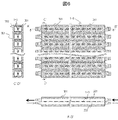
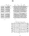
- thermoelectric conversion unit including a plurality of thermoelectric conversion modules having the same structure.
- the temperature at 90 ° C. at the pipe inlet decreases to about 40 ° C. at the pipe outlet, and the temperature difference between the heat source and the cooling source decreases as the distance from the inlet increases.
- thermoelectric conversion modules having the same structure cannot always obtain high thermoelectric conversion efficiency at each temperature difference.
- the present invention is based on this novel finding and has a configuration in which the thermoelectric conversion efficiency of each thermoelectric conversion module is uniform at each temperature difference in the thermoelectric conversion unit. Specifically, the thickness of the thermoelectric conversion material differs in each thermoelectric conversion module.
- thermoelectric conversion module since the temperature of warm water falls along the flow direction of warm water, the temperature difference concerning a thermoelectric conversion module becomes small in that direction. Therefore, the output of the thermoelectric conversion module decreases along the flow direction of the hot water. Furthermore, in the thermoelectric conversion module sandwiched between the hot water pipe and the cold water pipe, the amount of heat determined by the thermal conductivity of the thermoelectric conversion module flows in the temperature difference direction of the module, and the magnitude of the heat conductivity increases. As it grows. On the other hand, when the thermal conductivity is large, the temperature difference is small, and there is an optimum dimension for the output of the thermoelectric conversion module determined by the temperature difference and the heat quantity. A method for determining the thickness t of the thermoelectric conversion material as the optimum dimension will be described.
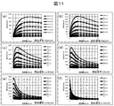
- thermoelectric conversion unit of FIG. 1 For example, it can be seen that a thickness of 1 mm or more is required for a heat source at 90 ° C. in order to obtain an output of 500 W / m 2 of thermal power generation required for industrial exhaust heat recovery. Moreover, when the temperature of the heat source decreases, the lower limit value of the thickness of the thermoelectric conversion module increases. Furthermore, it can be seen that a heat source of 60 ° C. or lower cannot obtain 500 W / m 2 at any thickness. It is necessary to set the thickness to 1 mm or more when using a 90 ° C. heat source, 1.5 mm or more when using a 80 ° C. heat source, and 3.5 to 10 mm when using a 70 ° C. heat source. Therefore, in the thermoelectric conversion unit of FIG.
- thermoelectric conversion material of the thermoelectric conversion module it is desirable to modulate the thickness of the thermoelectric conversion material of the thermoelectric conversion module applied in accordance with the flow direction of the hot water.
- the thickness of the thermoelectric conversion material to be applied is determined by the temperature of the heat source and the cooling source at the position of the thermoelectric conversion module on which the material is mounted, and the thermal conductivity of the material.
- thermoelectric conversion module when the thickness of the thermoelectric conversion material used for the thermoelectric conversion module is changed in the same thermoelectric conversion unit according to the environment, the thickness of the thermoelectric conversion module also changes. If thermoelectric conversion modules with different thicknesses are arranged in parallel, the shape of the hot water pipe and the thickness of the cold water pipe will not be uniform and the structure will be complicated, and the flow of hot water and cold water in the pipe will not be uniform. The output of the thermoelectric conversion module or thermoelectric conversion unit decreases. Therefore, it is desirable that the thickness of the thermoelectric conversion module is substantially constant even if the thickness of the thermoelectric conversion material changes.
- thermoelectric conversion module constant within thermoelectric conversion unit
- a material with high thermal conductivity and low electrical resistance such as copper or aluminum
- thermoelectric conversion unit capable of generating power with high thermoelectric conversion efficiency can be provided.
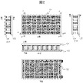
- FIG. 9 shows a thermoelectric conversion unit having a structure capable of entering water so that hot water and cold water flow in directions substantially orthogonal to each other with respect to the thermoelectric conversion unit 8 shown in FIG. 9 is a top view
- FIG. 9 is a cross-sectional view taken along the line A′B ′
- the left-hand view shown in FIG. 9 is a cross-sectional view taken along the line C′D ′.
- the hot water pipe 201 and the cold water pipe 202 are arranged so as to be orthogonal to each other, and the thermoelectric conversion modules (1 to 3) are arranged at the intersections.
- the flow of hot water as shown by the arrow in the cross-sectional A′-B ′ diagram is set, the cold water flows in the direction 401 or vice versa.
- thermoelectric conversion unit capable of generating power with high thermoelectric conversion efficiency can be provided.
Abstract
Description
前記熱電変換モジュールの前記n型及びp型熱電変換材料の厚さ方向の上下面に設置され、前記熱電変換モジュールに温度差を付与し、前記熱電変換材料のゼーベック効果により発電するための熱源および冷却源をそれぞれ供給するための供給手段と、を有し、
複数の前記熱電変換モジュールは並列接続され、
隣接する前記熱電変換モジュールの一方、あるいは複数の前記熱電変換モジュールの中の少なくとも一つは、前記熱電変換材料の厚さ、材料種および前記電極の厚さの少なくとも一つが他の熱電変換モジュールとは異なることを特徴とする熱電変換ユニットとする。
また、電力を取り出すための電極で接続されたn型熱電変換材料とp型熱電変換材料の複数対で構成される複数の熱電変換モジュールと、
前記熱電変換モジュールの前記n型及びp型熱電変換材料の厚さ方向の上下面に設置され、前記熱電変換モジュールに温度差を付与し、前記熱電変換材料のゼーベック効果により発電するための熱源および冷却源をそれぞれ供給するための供給手段と、を有し、
複数の前記熱電変換モジュールは並列接続され、
隣接する前記熱電変換モジュールの一方、あるいは複数の前記熱電変換モジュールの中の少なくとも一つは、前記熱電変換材料の厚さ、材料種および前記電極の厚さの少なくとも一つが他の熱電変換モジュールとは異なり、
熱源温度をTh、冷却源温度Tcを、熱電変換材料の熱伝導率をκ、熱電変換材料の材料性能定数をm0、熱源の熱伝達率をαh、冷却源の熱伝達率をαc、温水及び冷水の流速をv、熱源及び冷却源の温度依存特有の定数をそれぞれAh、Acとした場合、
αh=Ahv
αc=Acv
で表され、
前記熱電変換材料の厚さtは、
500W/m2≧[(Th-Tc)2/{(1/αh)+(t/κ)+(1/αc)}]×[(m0-1)/{m0(Th+273)+(Tc+273)}]
の式を満たす厚さtが選択されることを特徴とする熱電変換ユニットとする。
Q=ηmax×H ……(1)
で表すことができる。
ここで、最大変換効率ηmaxは、
ηmax=(ΔT/Th)(m0-1)/[m0+(Tc/Th)]……(2)
ΔT/Th=ηc,ΔT(温度差)=Th-Tc(Th:高温側の温度,Tc:低温側の温度),m0=(1+ZT)1/2
ここでZTは、熱電変換材料の無次元性能指数を表し
Z=S2/ρκ
S:ゼーベック係数,ρ:比抵抗,κ:熱伝導率
と表すことができる。
一方、本発明の構造における熱流Hは、
αh:熱源(温水)の熱伝達率、αcは冷却源(冷水)の熱伝達率、v:温水・冷水の流速としたときに
H=1/[(1/αh)+(t/κ)+(1/αc)] ……(3)
で表記できる。ここで
αh=Ahv、αc=AcvでありAh、Acはそれぞれ温水及び冷水の温度依存する特有の定数をあらわす。
(1)式に(2)式と(3)式を代入して
1つの熱電変換モジュールの出力密度Q(W/m2)は、
Q=[(Th-Tc)2/{(1/αh)+(t/κ)+(1/αc)}]
×[(m0-1)/{m0(Th+273)+(Tc+273)}]……(4)
を得る。
500≧[(Th-Tc)2/{(1/αh)+(t/κ)+(1/αc)}]
×[(m0-1)/{m0(Th+273)+(Tc+273)}]
を満たすように熱電変換材料の厚さtを選ぶことができる。
以下、図面を参照しながら本発明の実施例を説明する。
Bi-Te系、Pb-Te系、Si-Ge、Mg-Si系等の化合物半導体、
(2)NaxCoO2(0.3≦x≦0.8)、(ZnO)mIn2O3(1≦m≦19)系の酸化物材料
(3)Zn-Sb系、Co-Sb系、Fe-Sb系等のスクッテルダイト化合物
(4)Fe2VAlやZrNiSn等の金属間化合物で構成されるホイスラー合金
このような材料群において、熱電変換モジュールや熱電変換ユニットの出力を左右する無次元性能指数ZT(Tは温度)は最大1程度であるが、無毒・低コストなど環境・資源面において優位な材料での高性能化が期待されている。

Claims (15)
- 電力を取り出すための電極で接続されたn型熱電変換材料とp型熱電変換材料の複数対で構成される複数の熱電変換モジュールと、
前記熱電変換モジュールの前記n型及びp型熱電変換材料の厚さ方向の上下面に設置され、前記熱電変換モジュールに温度差を付与し、前記熱電変換材料のゼーベック効果により発電するための熱源および冷却源をそれぞれ供給するための供給手段と、を有し、
複数の前記熱電変換モジュールは並列接続され、
隣接する前記熱電変換モジュールの一方、あるいは複数の前記熱電変換モジュールの中の少なくとも一つは、前記熱電変換材料の厚さ、材料種および前記電極の厚さの少なくとも一つが他の熱電変換モジュールとは異なることを特徴とする熱電変換ユニット。 - 請求項1に記載の熱電変換ユニットにおいて、
前記熱電変換モジュールを構成する電極と前記熱源との間には、高熱伝導率絶縁材が配置されることを特徴とする熱電変換ユニット。 - 請求項1に記載の熱電変換ユニットにおいて、
前記熱電変換モジュールは、真空封止により機密にパッケージされていることを特徴とする熱電変換ユニット。 - 請求項1に記載の熱電変換ユニットにおいて
前記熱源および冷却源を供給するための手段は、液媒を流す配管をそれぞれ含み、複数の前記熱電変換モジュールに隣接して配置されていることを特徴とする熱電変換ユニット。 - 請求項4に記載の熱電変換ユニットにおいて、
それぞれの前記配管は、熱液媒と冷液媒の流れがほぼ平行あるいはほぼ直交するように配置されることを特徴とする熱電変換ユニット。 - 請求項1に記載の熱電変換ユニットにおいて、
前記熱電変換材料はホイスラー合金から構成され、
上記ホイスラー合金はFe、元素Xと元素Yで構成され、
前記元素Xは、Ti、Zr、Hf、V、Nb、Ta、Cr、Mo、W、Sc、Yからなる群の少なくともひとつであり、
前記元素Yは、Si、Ge、Sn、Al、Ga、In、Zn、Cd、Hg、Ca、Sr、Ba、P、As、Sb、Biからなる群の少なくともひとつであることを特徴とする熱電変換ユニット。 - 請求項6に記載の熱電変換ユニットにおいて、
前記ホイスラー合金の結晶粒径は、1μm以下であることを特徴とする熱電変換ユニット。 - 電力を取り出すための電極で接続されたn型熱電変換材料とp型熱電変換材料の複数対で構成される複数の熱電変換モジュールと、
前記熱電変換モジュールの前記n型及びp型熱電変換材料の厚さ方向の上下面に設置され、前記熱電変換モジュールに温度差を付与し、前記熱電変換材料のゼーベック効果により発電するための熱源および冷却源をそれぞれ供給するための供給手段と、を有し、
複数の前記熱電変換モジュールは並列接続され、
隣接する前記熱電変換モジュールの一方、あるいは複数の前記熱電変換モジュールの中の少なくとも一つは、前記熱電変換材料の厚さ、材料種および前記電極の厚さの少なくとも一つが他の熱電変換モジュールとは異なり、
熱源温度をTh、冷却源温度Tcを、熱電変換材料の熱伝導率をκ、熱電変換材料の材料性能定数をm0、熱源の熱伝達率をαh、冷却源の熱伝達率をαc、温水及び冷水の流速をv、熱源及び冷却源の温度依存特有の定数をそれぞれAh、Acとした場合、
αh=Ahv
αc=Acv
で表され、
前記熱電変換材料の厚さtは、
500W/m2≧[(Th-Tc)2/{(1/αh)+(t/κ)+(1/αc)}]
×[(m0-1)/{m0(Th+273)+(Tc+273)}]
の式を満たす厚さtが選択されることを特徴とする熱電変換ユニット。 - 請求項8に記載の熱電変換ユニットにおいて、
前記熱電変換モジュールを構成する電極と前記熱源の間には、高熱伝導率絶縁材が配置されることを特徴とする熱電変換ユニット。 - 請求項8に記載の熱電変換ユニットにおいて、
前記熱電変換モジュールは、真空封止により機密にパッケージされていることを特徴とする熱電変換ユニット。 - 請求項8に記載の熱電変換ユニットにおいて
前記熱源及び冷却源を供給するための手段は、液媒を流す配管をそれぞれ含み、複数の前記熱電変換モジュールに隣接して配置されていることを特徴とする熱電変換ユニット。 - 請求項11に記載の熱電変換ユニットにおいて、
それぞれの前記配管は、熱液媒と冷液媒の流れがほぼ平行あるいはほぼ直交するように配置されることを特徴とする熱電変換ユニット。 - 請求項8に記載の熱電変換ユニットにおいて、
前記熱電変換材料はホイスラー合金から構成され、
前記ホイスラー合金はFe、元素Xと元素Yで構成され、
前記元素Xは、Ti、Zr、Hf、V、Nb、Ta、Cr、Mo、W、Sc、Yからなる群の少なくともひとつであり、
前記元素Yは、Si、Ge、Sn、Al、Ga、In、Zn、Cd、Hg、Ca、Sr、Ba、P、As、Sb、Biからなる群の少なくともひとであることを特徴とする熱電変換ユニット。 - 請求項13に記載の熱電変換ユニットにおいて、
前記ホイスラー合金の結晶粒径は、1μm以下であることを特徴とする熱電変換ユニット。 - 請求項8に記載の熱電変換ユニットにおいて、
複数の前記熱電変換モジュールは、前記熱電変換材料の厚さが互いに異なる場合であっても、ほぼ厚さが等しくなるように作製されていることを特徴とする熱電変換ユニット。
Priority Applications (4)
| Application Number | Priority Date | Filing Date | Title |
|---|---|---|---|
| CN201380075040.6A CN105051925B (zh) | 2013-03-27 | 2013-03-27 | 高效率热电转换装置 |
| US14/780,514 US20160043297A1 (en) | 2013-03-27 | 2013-03-27 | High efficiency thermoelectric conversion unit |
| JP2015507791A JPWO2014155591A1 (ja) | 2013-03-27 | 2013-03-27 | 高効率熱電変換ユニット |
| PCT/JP2013/059153 WO2014155591A1 (ja) | 2013-03-27 | 2013-03-27 | 高効率熱電変換ユニット |
Applications Claiming Priority (1)
| Application Number | Priority Date | Filing Date | Title |
|---|---|---|---|
| PCT/JP2013/059153 WO2014155591A1 (ja) | 2013-03-27 | 2013-03-27 | 高効率熱電変換ユニット |
Publications (1)
| Publication Number | Publication Date |
|---|---|
| WO2014155591A1 true WO2014155591A1 (ja) | 2014-10-02 |
Family
ID=51622667
Family Applications (1)
| Application Number | Title | Priority Date | Filing Date |
|---|---|---|---|
| PCT/JP2013/059153 WO2014155591A1 (ja) | 2013-03-27 | 2013-03-27 | 高効率熱電変換ユニット |
Country Status (4)
| Country | Link |
|---|---|
| US (1) | US20160043297A1 (ja) |
| JP (1) | JPWO2014155591A1 (ja) |
| CN (1) | CN105051925B (ja) |
| WO (1) | WO2014155591A1 (ja) |
Cited By (3)
| Publication number | Priority date | Publication date | Assignee | Title |
|---|---|---|---|---|
| JP2020035953A (ja) * | 2018-08-31 | 2020-03-05 | 日産自動車株式会社 | 熱電発電装置 |
| WO2020049852A1 (ja) * | 2018-09-03 | 2020-03-12 | 住友電気工業株式会社 | 熱電変換素子、熱電変換モジュール、光センサ、熱電変換材料の製造方法および熱電変換素子の製造方法 |
| JP2020068652A (ja) * | 2018-10-22 | 2020-04-30 | Jfeスチール株式会社 | 製造設備列および熱電発電方法 |
Families Citing this family (2)
| Publication number | Priority date | Publication date | Assignee | Title |
|---|---|---|---|---|
| WO2015178929A1 (en) * | 2014-05-23 | 2015-11-26 | Laird Durham, Inc. | Thermoelectric heating/cooling devices including resistive heaters |
| CN106093654A (zh) * | 2016-07-11 | 2016-11-09 | 浙江大学 | 热电模组热电转换效率的测试装置及其测试方法 |
Citations (6)
| Publication number | Priority date | Publication date | Assignee | Title |
|---|---|---|---|---|
| JPH05315656A (ja) * | 1991-11-06 | 1993-11-26 | Tokin Corp | 熱電気変換装置 |
| JPH11257789A (ja) * | 1998-03-10 | 1999-09-24 | Hitachi Ltd | 熱電冷却装置及びそれを用いた構造物 |
| JP2000286469A (ja) * | 1999-03-30 | 2000-10-13 | Nissan Motor Co Ltd | 熱電発電装置 |
| JP2006156993A (ja) * | 2004-11-02 | 2006-06-15 | Showa Denko Kk | 熱電変換モジュールおよびそれを備えた熱電発電装置と方法、並びに、廃熱回収システム、太陽熱利用システム、ペルチェ冷熱システム、原子力熱電発電システム、バイオマスシステム |
| JP2006203186A (ja) * | 2004-12-24 | 2006-08-03 | Showa Denko Kk | 熱電半導体合金の製造方法および熱電変換モジュールならびに熱電発電装置 |
| JP2010135643A (ja) * | 2008-12-05 | 2010-06-17 | Toshiba Corp | 熱電変換装置、熱電発電システム、および熱電発電方法 |
Family Cites Families (14)
| Publication number | Priority date | Publication date | Assignee | Title |
|---|---|---|---|---|
| JPH0638560A (ja) * | 1992-07-20 | 1994-02-10 | Aisin Seiki Co Ltd | 排気ガス発電装置 |
| US5936193A (en) * | 1997-05-09 | 1999-08-10 | Parise; Ronald J. | Nighttime solar cell |
| JPH11261117A (ja) * | 1998-03-12 | 1999-09-24 | Nissan Motor Co Ltd | 熱電変換モジュール及びそれを用いた排熱発電装置 |
| JP2001196650A (ja) * | 2000-01-13 | 2001-07-19 | Komatsu Ltd | 熱電変換素子モジュール |
| US20060090787A1 (en) * | 2004-10-28 | 2006-05-04 | Onvural O R | Thermoelectric alternators and thermoelectric climate control devices with controlled current flow for motor vehicles |
| US20060124165A1 (en) * | 2004-12-09 | 2006-06-15 | Marlow Industries, Inc. | Variable watt density thermoelectrics |
| KR20090103874A (ko) * | 2006-11-13 | 2009-10-01 | 메사추세츠 인스티튜트 오브 테크놀로지 | 태양 열전기 변환 |
| JP4858976B2 (ja) * | 2007-01-31 | 2012-01-18 | 独立行政法人産業技術総合研究所 | 複合化した熱電変換材料 |
| WO2009008127A1 (ja) * | 2007-07-09 | 2009-01-15 | Kabushiki Kaisha Toshiba | 熱電変換モジュールとそれを用いた熱交換器、熱電温度調節装置および熱電発電装置 |
| JP2009099686A (ja) * | 2007-10-15 | 2009-05-07 | Sumitomo Chemical Co Ltd | 熱電変換モジュール |
| US7994415B2 (en) * | 2008-11-21 | 2011-08-09 | Panasonic Corporation | Thermoelectric device and power generation method using the same |
| JP5742174B2 (ja) * | 2009-12-09 | 2015-07-01 | ソニー株式会社 | 熱電発電装置、熱電発電方法及び電気信号検出方法 |
| JP5785789B2 (ja) * | 2011-06-13 | 2015-09-30 | パナソニック環境エンジニアリング株式会社 | ボイラ廃熱利用システム |
| KR102065327B1 (ko) * | 2012-03-21 | 2020-01-13 | 린텍 가부시키가이샤 | 열전 변환 재료 및 그 제조 방법 |
-
2013
- 2013-03-27 CN CN201380075040.6A patent/CN105051925B/zh not_active Expired - Fee Related
- 2013-03-27 WO PCT/JP2013/059153 patent/WO2014155591A1/ja active Application Filing
- 2013-03-27 US US14/780,514 patent/US20160043297A1/en not_active Abandoned
- 2013-03-27 JP JP2015507791A patent/JPWO2014155591A1/ja active Pending
Patent Citations (6)
| Publication number | Priority date | Publication date | Assignee | Title |
|---|---|---|---|---|
| JPH05315656A (ja) * | 1991-11-06 | 1993-11-26 | Tokin Corp | 熱電気変換装置 |
| JPH11257789A (ja) * | 1998-03-10 | 1999-09-24 | Hitachi Ltd | 熱電冷却装置及びそれを用いた構造物 |
| JP2000286469A (ja) * | 1999-03-30 | 2000-10-13 | Nissan Motor Co Ltd | 熱電発電装置 |
| JP2006156993A (ja) * | 2004-11-02 | 2006-06-15 | Showa Denko Kk | 熱電変換モジュールおよびそれを備えた熱電発電装置と方法、並びに、廃熱回収システム、太陽熱利用システム、ペルチェ冷熱システム、原子力熱電発電システム、バイオマスシステム |
| JP2006203186A (ja) * | 2004-12-24 | 2006-08-03 | Showa Denko Kk | 熱電半導体合金の製造方法および熱電変換モジュールならびに熱電発電装置 |
| JP2010135643A (ja) * | 2008-12-05 | 2010-06-17 | Toshiba Corp | 熱電変換装置、熱電発電システム、および熱電発電方法 |
Cited By (6)
| Publication number | Priority date | Publication date | Assignee | Title |
|---|---|---|---|---|
| JP2020035953A (ja) * | 2018-08-31 | 2020-03-05 | 日産自動車株式会社 | 熱電発電装置 |
| JP7187899B2 (ja) | 2018-08-31 | 2022-12-13 | 日産自動車株式会社 | 熱電発電装置 |
| WO2020049852A1 (ja) * | 2018-09-03 | 2020-03-12 | 住友電気工業株式会社 | 熱電変換素子、熱電変換モジュール、光センサ、熱電変換材料の製造方法および熱電変換素子の製造方法 |
| JPWO2020049852A1 (ja) * | 2018-09-03 | 2021-09-02 | 住友電気工業株式会社 | 熱電変換素子、熱電変換モジュール、光センサ、熱電変換材料の製造方法および熱電変換素子の製造方法 |
| US11716903B2 (en) | 2018-09-03 | 2023-08-01 | Sumitomo Electric Industries, Ltd. | Thermoelectric conversion element, thermoelectric conversion module, optical sensor, method of producing thermoelectric conversion material, and method of producing thermoelectric conversion element |
| JP2020068652A (ja) * | 2018-10-22 | 2020-04-30 | Jfeスチール株式会社 | 製造設備列および熱電発電方法 |
Also Published As
| Publication number | Publication date |
|---|---|
| CN105051925B (zh) | 2018-07-17 |
| US20160043297A1 (en) | 2016-02-11 |
| JPWO2014155591A1 (ja) | 2017-02-16 |
| CN105051925A (zh) | 2015-11-11 |
Similar Documents
| Publication | Publication Date | Title |
|---|---|---|
| LeBlanc et al. | Material and manufacturing cost considerations for thermoelectrics | |
| JP6798339B2 (ja) | マグネシウム系熱電変換材料の製造方法、マグネシウム系熱電変換素子の製造方法、マグネシウム系熱電変換材料、マグネシウム系熱電変換素子、熱電変換装置 | |
| WO2014155591A1 (ja) | 高効率熱電変換ユニット | |
| US20140261608A1 (en) | Thermal Interface Structure for Thermoelectric Devices | |
| JP6949850B2 (ja) | 熱電変換材料、熱電変換素子および熱電変換モジュール | |
| JP2012124469A (ja) | 熱電素子及び熱電モジュール | |
| JP2013016685A (ja) | 熱電変換材料、熱電変換素子およびその作製方法 | |
| KR102083611B1 (ko) | 열변환장치 | |
| US20120305044A1 (en) | Thermal transfer and power generation systems, devices and methods of making the same | |
| JP6593870B2 (ja) | 熱電変換材料、およびそれを用いた熱電発電素子、ペルチェ冷却用素子 | |
| US20160056363A1 (en) | Freestanding Thermoelectric Energy Conversion Device | |
| O'Dwyer et al. | Scientific and technical challenges in thermal transport and thermoelectric materials and devices | |
| WO2016031572A1 (ja) | 熱電材料、熱電変換素子及び熱電材料から成るπ型モジュール群乃至π型モジュール群以外と熱変電換素子の組み合わせから成るモジュール群 | |
| CN111433924A (zh) | 热转换设备 | |
| KR102022429B1 (ko) | 냉각용 열전모듈 및 그 제조방법 | |
| US20180287517A1 (en) | Phase change inhibited heat-transfer thermoelectric power generation device and manufacturing method thereof | |
| WO2017146095A1 (ja) | マグネシウム系熱電変換材料の製造方法、マグネシウム系熱電変換素子の製造方法、マグネシウム系熱電変換材料、マグネシウム系熱電変換素子、熱電変換装置 | |
| US20090151767A1 (en) | Composite thermoelectric material and methods for making | |
| US20140360549A1 (en) | Thermoelectric Module and Method of Making Same | |
| KR102368960B1 (ko) | 열전소자 및 이를 포함하는 열전변환장치 | |
| US9543493B2 (en) | Packaging for thermoelectric subcomponents | |
| JP6847410B2 (ja) | 熱電変換材料及び熱電変換モジュール | |
| KR102065111B1 (ko) | 방열-열전 핀, 이를 포함하는 열전모듈 및 열전장치 | |
| JP5540289B2 (ja) | 熱電発電デバイスの製造方法 | |
| KR20210090998A (ko) | 발전장치 |
Legal Events
| Date | Code | Title | Description |
|---|---|---|---|
| WWE | Wipo information: entry into national phase |
Ref document number: 201380075040.6 Country of ref document: CN |
|
| 121 | Ep: the epo has been informed by wipo that ep was designated in this application |
Ref document number: 13880259 Country of ref document: EP Kind code of ref document: A1 |
|
| ENP | Entry into the national phase |
Ref document number: 2015507791 Country of ref document: JP Kind code of ref document: A |
|
| WWE | Wipo information: entry into national phase |
Ref document number: 14780514 Country of ref document: US |
|
| NENP | Non-entry into the national phase |
Ref country code: DE |
|
| 122 | Ep: pct application non-entry in european phase |
Ref document number: 13880259 Country of ref document: EP Kind code of ref document: A1 |