WO2014155462A1 - 撮像レンズおよびこれを備えた撮像装置 - Google Patents
撮像レンズおよびこれを備えた撮像装置 Download PDFInfo
- Publication number
- WO2014155462A1 WO2014155462A1 PCT/JP2013/007606 JP2013007606W WO2014155462A1 WO 2014155462 A1 WO2014155462 A1 WO 2014155462A1 JP 2013007606 W JP2013007606 W JP 2013007606W WO 2014155462 A1 WO2014155462 A1 WO 2014155462A1
- Authority
- WO
- WIPO (PCT)
- Prior art keywords
- lens
- group
- negative
- positive
- imaging
- Prior art date
- Legal status (The legal status is an assumption and is not a legal conclusion. Google has not performed a legal analysis and makes no representation as to the accuracy of the status listed.)
- Ceased
Links
Images


Classifications
-
- G—PHYSICS
- G02—OPTICS
- G02B—OPTICAL ELEMENTS, SYSTEMS OR APPARATUS
- G02B13/00—Optical objectives specially designed for the purposes specified below
- G02B13/04—Reversed telephoto objectives
-
- G—PHYSICS
- G02—OPTICS
- G02B—OPTICAL ELEMENTS, SYSTEMS OR APPARATUS
- G02B27/00—Optical systems or apparatus not provided for by any of the groups G02B1/00 - G02B26/00, G02B30/00
- G02B27/0025—Optical systems or apparatus not provided for by any of the groups G02B1/00 - G02B26/00, G02B30/00 for optical correction, e.g. distorsion, aberration
-
- G—PHYSICS
- G02—OPTICS
- G02B—OPTICAL ELEMENTS, SYSTEMS OR APPARATUS
- G02B9/00—Optical objectives characterised both by the number of the components and their arrangements according to their sign, i.e. + or -
- G02B9/64—Optical objectives characterised both by the number of the components and their arrangements according to their sign, i.e. + or - having more than six components
-
- G—PHYSICS
- G02—OPTICS
- G02B—OPTICAL ELEMENTS, SYSTEMS OR APPARATUS
- G02B13/00—Optical objectives specially designed for the purposes specified below
- G02B13/001—Miniaturised objectives for electronic devices, e.g. portable telephones, webcams, PDAs, small digital cameras
- G02B13/0015—Miniaturised objectives for electronic devices, e.g. portable telephones, webcams, PDAs, small digital cameras characterised by the lens design
-
- G—PHYSICS
- G02—OPTICS
- G02B—OPTICAL ELEMENTS, SYSTEMS OR APPARATUS
- G02B13/00—Optical objectives specially designed for the purposes specified below
- G02B13/001—Miniaturised objectives for electronic devices, e.g. portable telephones, webcams, PDAs, small digital cameras
- G02B13/0015—Miniaturised objectives for electronic devices, e.g. portable telephones, webcams, PDAs, small digital cameras characterised by the lens design
- G02B13/002—Miniaturised objectives for electronic devices, e.g. portable telephones, webcams, PDAs, small digital cameras characterised by the lens design having at least one aspherical surface
- G02B13/0045—Miniaturised objectives for electronic devices, e.g. portable telephones, webcams, PDAs, small digital cameras characterised by the lens design having at least one aspherical surface having five or more lenses
-
- G—PHYSICS
- G02—OPTICS
- G02B—OPTICAL ELEMENTS, SYSTEMS OR APPARATUS
- G02B5/00—Optical elements other than lenses
- G02B5/005—Diaphragms
-
- G—PHYSICS
- G02—OPTICS
- G02B—OPTICAL ELEMENTS, SYSTEMS OR APPARATUS
- G02B9/00—Optical objectives characterised both by the number of the components and their arrangements according to their sign, i.e. + or -
Definitions
- the present invention relates to an imaging lens and an imaging apparatus including the imaging lens. More specifically, the imaging lens includes an imaging lens that can be suitably used for a digital camera, a broadcast camera, a surveillance camera, an in-vehicle camera, and the like, and the imaging lens.
- the present invention relates to an imaging device.
- Patent Documents 1 to 3 listed below Can be mentioned.
- An imaging lens used for a camera in the above field is required to have a small F number and a wide angle. Furthermore, since surveillance cameras and in-vehicle cameras are often used for both day and night, various aberrations are required to be corrected well from the visible range to the near infrared range. In recent years, the number of pixels of an image sensor mounted on a camera has been increased, and the imaging lens is also required to have high performance capable of handling high pixels.
- the lens system described in Patent Document 1 cannot be said to have a small F number, and further widening of the angle is desired.
- the lens system described in Patent Document 2 has a wide angle but cannot be said to have a small F number, and there is room for improvement in aberration correction.
- none of the lens systems described in Patent Documents 1 to 3 is intended to satisfactorily correct various aberrations from the visible range to the near infrared range.
- the present invention has been made in view of such problems, and an object of the present invention is to provide an image pickup having high optical performance with various aberrations corrected well from the visible range to the near infrared range while ensuring a small F number and a wide angle.
- An object of the present invention is to provide a lens and an imaging apparatus including the imaging lens.
- the imaging lens of the present invention is substantially composed of a front group having a negative refractive power, an aperture, and a rear group having a positive refractive power in order from the object side. It includes a front negative lens group having two or more negative lenses and having negative refractive power, one negative lens and one positive lens, and the positive lens is disposed closest to the object side to have positive refractive power.
- the front group includes a positive lens group, and the rear group includes one negative lens and one positive lens.
- the refractive index with respect to the d-line of the most negative lens in the front group positive lens group, and the Abbe with respect to the d-line When the numbers are Nan and ⁇ an, respectively, the following conditional expression (1) is satisfied. Nan + 0.01 ⁇ ⁇ an ⁇ 2.15 (1)
- conditional expression (3) is satisfied, where Dab is the air space on the optical axis between the front group and the rear group, and f is the focal length of the entire system. More preferably, the following conditional expression (3 ′) is satisfied, and it is even more preferable that the following conditional expression (3 ′′) is satisfied.
- 0.05 ⁇ Dab / f ⁇ 1.55 (3) 0.10 ⁇ Dab / f ⁇ 1.00 (3 ′) 0.10 ⁇ Dab / f ⁇ 0.55 (3 ′′)
- the following conditional expression (4) is satisfied when the Abbe number with respect to the d-line of the positive lens closest to the object side in the rear group is ⁇ bp, and the following conditional expression (4 ′ ) Is more preferable.
- the front group negative lens group is substantially composed of two negative meniscus lenses having convex surfaces facing the object side.
- the rear group includes two sets of cemented lenses in which a positive lens and a negative lens are cemented.
- the cemented surfaces of these two groups of cemented lenses have concave surfaces facing the object side. .
- the rear group is substantially composed of, in order from the object side, a positive lens, a cemented lens of a positive lens and a negative lens, and a cemented lens of a positive lens and a negative lens.
- substantially composed of the above “substantially composed of” means, in addition to the above-described constituent requirements, lenses other than lenses that do not substantially have power, lenses other than lenses such as a diaphragm, a cover glass, and a filter. It is intended that an optical element, a lens flange, a lens barrel, a mechanism portion such as a camera shake correction mechanism, and the like may be included.
- the surface shape of the lens and the sign of the refractive power in the imaging lens of the present invention described above are considered in the paraxial region when an aspheric surface is included.
- the imaging apparatus of the present invention is characterized by including the imaging lens of the present invention.
- the configuration of each lens group is preferably set, and conditional expression (1) Since the lens material is selected so as to satisfy the above, an imaging lens having high optical performance with various aberrations corrected satisfactorily from the visible region to the near infrared region while ensuring a small F number and a wide angle, and this An imaging apparatus provided with such an imaging lens can be provided.
- Sectional drawing which shows the structure and optical path of an imaging lens concerning one Embodiment of this invention.
- Sectional drawing which shows the structure of the imaging lens of Example 1 of this invention
- Sectional drawing which shows the structure of the imaging lens of Example 2 of this invention
- Sectional drawing which shows the structure of the imaging lens of Example 3 of this invention.
- Sectional drawing which shows the structure of the imaging lens of Example 4 of this invention.
- 6 (A) to 6 (D) are diagrams showing aberrations of the image pickup lens of Example 1 of the present invention.
- FIGS. 7A to 7D are diagrams showing aberrations of the imaging lens according to Example 2 of the present invention.
- FIGS. 8A to 8D are diagrams showing aberrations of the image pickup lens of Example 3 of the present invention.
- 9A to 9D are graphs showing aberrations of the imaging lens according to Example 4 of the present invention.
- 1 is a schematic configuration diagram of an imaging apparatus according to an embodiment of the present invention.
- FIG. 1 is a cross-sectional view showing a configuration of an imaging lens according to an embodiment of the present invention.
- the example shown in FIG. 1 corresponds to Example 1 described later.
- the left side is the object side
- the right side is the image side.
- an on-axis light beam 2 and a maximum off-axis light beam 3 are also shown.
- the imaging lens 1 includes, in order from the object side along the optical axis Z, a front group Ga having a negative refractive power, an aperture stop St, and a rear group Gb having a positive refractive power. It is substantially composed. Note that the aperture stop St shown in FIG. 1 does not necessarily indicate the size or shape, but indicates the position on the optical axis Z.
- the imaging device When the imaging lens is mounted on the imaging device, the imaging device is configured to include a cover glass for protecting the imaging device and various filters such as a low-pass filter and an infrared cut filter according to the specifications of the imaging device.
- FIG. 1 shows an example in which the parallel plate-like optical member PP assuming these is arranged between the lens surface closest to the image side and the image plane Sim.
- the optical member PP is not an essential component for the imaging lens of the present invention.
- the front group Ga includes, in order from the object side, a front group negative lens group GaN including two or more negative lenses having negative refractive power, one negative lens, and one positive lens, and is most positive on the object side.
- a front-group positive lens group GaP having a positive refracting power and having a lens disposed thereon.
- the rear group Gb is configured to include one negative lens and one positive lens.
- the front group negative lens group GaN includes a negative lens La1 and a negative lens La2 in order from the object side
- the front group positive lens group GaP includes a positive lens in order from the object side
- the rear group Gb includes a lens La3 and a negative lens La4.
- the rear group Gb includes, in order from the object side, a positive lens Lb1, a cemented lens of the positive lens Lb2 and the negative lens Lb3, a positive lens Lb4, and a negative lens. It consists of a cemented lens of Lb5.
- the imaging lens 1 is advantageous for widening the angle by arranging a lens group having a negative refractive power closest to the object side, followed by a negative leading power array followed by a lens group having a positive refractive power.
- the front group negative lens group GaN includes two or more negative lenses, the negative power of the front group negative lens group GaN can be shared by a plurality of lenses, thereby achieving a wide angle of view while achieving a wide angle of view. It is easy to suppress aberrations that occur during the process, particularly distortion.
- the front group positive lens group GaP can also correct spherical aberration that the rear group Gb on the image side from the aperture stop St should bear. Since it can be shared, it is advantageous for realizing an optical system with a small F number. Since the front group positive lens group GaP includes at least one negative lens and one positive lens, it becomes easy to correct various aberrations including chromatic aberration in a balanced manner. By including at least one negative lens and one positive lens in the rear group Gb, it becomes easy to correct various aberrations including chromatic aberration in a balanced manner even on the image side from the aperture stop St.
- the front group negative lens group GaN may be composed of two negative lenses.
- the total length of the front group negative lens group GaN is suppressed with the minimum number of lenses necessary.
- the front group negative lens group GaN may be constituted by two negative meniscus lenses having convex surfaces facing the object side, which is advantageous for widening the angle.
- the positive lens is arranged on the most object side so that the positive lens converges on divergent light emitted from the front group negative lens group GaN and incident on the front group positive lens group GaP. This is advantageous in suppressing aberration generation.
- the front group positive lens group GaP may have a two-lens configuration, and in the case of the two-lens configuration, the front group positive lens group GaP can be configured with a minimum number of lenses to reduce the total length.
- the positive lens By making the positive lens a biconvex lens, positive power can be shared by both the object side surface and the image side surface, and by making the negative lens a biconcave lens, both the object side surface and the image side surface can be shared. Since negative power can be shared, a two-lens configuration including a biconvex lens and a biconcave lens in order from the object side is advantageous in suppressing spherical aberration.
- the front group positive lens group GaP may have a three-lens configuration including a positive lens, a negative lens, and a positive lens in order from the object side.
- a so-called triplet configuration When such a so-called triplet configuration is used, various aberrations are excellent. It is easy to construct an optical system with a small F number.
- the front group positive lens group GaP has a triplet configuration, it is preferable to arrange a biconvex lens, a biconcave lens, and a biconvex lens in order from the object side. In this case, spherical aberration and chromatic aberration, in particular, This is advantageous for correcting chromatic aberration in the near infrared region.
- the rear group Gb includes two sets of cemented lenses in which a positive lens and a negative lens are cemented. In this case, it is easy to correct chromatic aberration easily, and a favorable range from the visible range to the near infrared range is achieved. This is advantageous for correcting chromatic aberration.
- the cemented surfaces of these two groups of cemented lenses are both concave on the object side. Since the incident angle when the off-axis rays in the peripheral part are incident on these joint surfaces can be reduced, the amount of aberration can be suppressed, which is particularly advantageous for good correction of astigmatism.
- the rear group Gb has, in order from the object side, a cemented lens of a positive meniscus lens having a concave surface facing the object side and a negative meniscus lens having a concave surface facing the object side, and a concave surface facing the biconvex lens and the object side. It is preferable to include a cemented lens of a negative meniscus lens. In this case, it is further advantageous for good correction of astigmatism and chromatic aberration.
- the rear group Gb can be configured to include, in order from the object side, a positive lens, a cemented lens of a positive lens and a negative lens, and a cemented lens of a positive lens and a negative lens.
- a positive lens a cemented lens of a positive lens and a negative lens
- a cemented lens of a positive lens and a negative lens can make the Petzval sum close to 0, and can correct curvature of field and astigmatism caused by the negative refractive power of the front negative lens group GaN.
- the imaging lens 1 may be configured to include an aspherical lens.
- an aspherical lens it is advantageous for widening the angle, small F-number, and good aberration correction.
- the imaging lens 1 satisfies the following conditional expression (1) when the refractive index with respect to the d-line and the Abbe number with respect to the d-line of the negative lens closest to the image side of the front group positive lens group GaP are Nan and ⁇ an, respectively. It is configured. Nan + 0.01 ⁇ ⁇ an ⁇ 2.15 (1)
- Conditional expression (1) relates to the material of the negative lens close to the aperture stop St in the front group Ga. Selecting the material of the negative lens closest to the image side of the front group positive lens group GaP so as not to exceed the upper limit of conditional expression (1) is advantageous in correcting chromatic aberration, and various aberrations from the visible range to the near infrared range. This is advantageous for good correction. Further, satisfying conditional expression (1) makes it possible to correct chromatic aberration satisfactorily, which is advantageous for realizing an optical system having a small F number.
- the focal length of the front negative lens group GaN is faN and the focal length of the entire system is f. -1.0 ⁇ faN / f ⁇ -0.5 (2)
- Securing the negative refractive power of the front negative lens group GaN so that it does not fall below the lower limit of conditional expression (2) makes it easy to realize a wide angle.
- Suppressing the negative refractive power of the front negative lens group GaN so as not to exceed the upper limit of conditional expression (2) facilitates good correction of spherical aberration, which is advantageous for realizing an optical system with a small F number.
- the imaging lens 1 preferably satisfies the following conditional expression (3), where Dab is the air space on the optical axis between the front group Ga and the rear group Gb and the focal length of the entire system is f. . 0.05 ⁇ Dab / f ⁇ 1.55 (3)
- the arrangement of the aperture stop St is facilitated, and the spherical aberration is favorably corrected. It will be advantageous.
- the air gap on the optical axis between the front group Ga and the rear group Gb so as not to exceed the upper limit of the conditional expression (3), the total length of the lens system and the lens diameter can be suppressed. It becomes possible to make it a small-sized structure suitable for an industrial camera or the like.
- the imaging lens 1 satisfies the following conditional expression (4) when the Abbe number with respect to the d-line of the positive lens closest to the object side in the rear group Gb is ⁇ bp. ⁇ bp> 55 (4)
- Conditional expression (4) relates to the material of the positive lens close to the aperture stop St in the rear group Gb.
- Example 1 A cross-sectional view showing the configuration of the imaging lens of Example 1 is shown in FIG.
- the left side is the object side
- the right side is the image side
- a parallel plate-shaped optical member PP assuming a cover glass, various filters, and the like is disposed between the lens closest to the image side and the image plane Sim. Show.
- the group configuration of the imaging lens of Example 1 includes, in order from the object side, a front group Ga having a negative refractive power, an aperture stop St, and a rear group Gb having a positive refractive power.
- the front lens group GaN having a negative refracting power and the front lens group GaP having a positive refracting power are employed.
- the front group negative lens group GaN includes a negative lens La1 and a negative lens La2 in this order from the object side.
- the positive lens group GaP includes a positive lens La3 and a negative lens La4 in order from the object side
- the rear group Gb includes a positive lens Lb1, a positive lens Lb2, and a negative lens Lb3 in order from the object side.
- a cemented lens composed of a positive lens Lb4 and a negative lens Lb5.
- Table 1 shows basic lens data
- Table 2 shows aspheric coefficients as numerical data indicating the detailed configuration of the imaging lens of Example 1.
- the uppermost stage outside the frame of Table 1 shows the specifications regarding the d line
- f is the focal length of the entire system
- Bf is the back focus at the air equivalent distance
- 2 ⁇ is the full angle of view.
- the column of i shows the radius of curvature of the i-th surface
- the column of Di shows the surface spacing on the optical axis Z between the i-th surface and the i + 1-th surface.
- the bottom column of the column of Di is the surface interval between the most image side surface and the image surface Sim shown in Table 1.
- the sign of the radius of curvature is positive when the surface shape has a convex surface facing the object side, and negative when the surface shape has a convex surface facing the image side.
- the d-line (wavelength: 587.56 nm) of the j-th (j 1, 2, 3,%) Optical element that sequentially increases toward the image side with the most object-side component as the first.
- the column of ⁇ dj indicates the Abbe number for the d-line of the jth optical element.
- the basic lens data includes the aperture stop St and the optical member PP, and the surface number and the phrase (St) are described in the surface number column of the surface corresponding to the aperture stop St.
- the aspherical surface is marked with * in the surface number, and the paraxial radius of curvature is shown as the radius of curvature of the aspherical surface.
- Table 2 shows the aspheric coefficients of these aspheric surfaces.
- the numerical values “E ⁇ n” (n: integer) shown in Table 2 mean “ ⁇ 10 ⁇ n ”.
- ⁇ in formula (A) means the sum related to the term of m.
- Zd C ⁇ h 2 / ⁇ 1+ (1 ⁇ KA ⁇ C 2 ⁇ h 2 ) 1/2 ⁇ + ⁇ Am ⁇ h m (A)
- Zd Depth of aspheric surface (length of a perpendicular line drawn from a point on the aspherical surface at height h to a plane perpendicular to the optical axis where the aspherical vertex contacts)
- h Height (distance from the optical axis to the lens surface)
- C paraxial curvature KA
- FIGS. 6A to 6D show spherical aberration, astigmatism, distortion (distortion), and chromatic aberration of magnification (chromatic aberration of magnification) of the imaging lens of Example 1 when the object distance is infinity, respectively.
- Each aberration diagram is shown.
- FNo. Means F number, and ⁇ in other aberration diagrams means half angle of view.
- Each aberration diagram shows aberration with d-line (587.56 nm) as a reference wavelength, but spherical aberration diagram shows C-line (wavelength 656.27 nm), F-line (wavelength 486.13 nm), A′-line.
- Example 2 A cross-sectional view showing the configuration of the imaging lens of Example 2 is shown in FIG.
- the group configuration and schematic configuration of the imaging lens of the second embodiment are the same as those of the first embodiment described above except that the lens La3 and the lens La4 are cemented.
- Tables 3 and 4 show basic lens data and aspherical coefficients of the imaging lens of Example 2, respectively.
- FIGS. 7A to 7D show aberration diagrams of the imaging lens of Example 2.
- FIG. 4 is a cross-sectional view showing the configuration of the imaging lens of Example 3.
- the group configuration and schematic configuration of the imaging lens of Example 3 are the same as those of Example 2 described above.
- Tables 5 and 6 show basic lens data and aspheric coefficients of the imaging lens of Example 3, respectively.
- FIGS. 8A to 8D show aberration diagrams of the imaging lens of Example 3.
- FIG. 5 is a cross-sectional view showing the configuration of the imaging lens of Example 4.
- the group configuration and schematic configuration of the imaging lens of Example 4 are the same except that the front group positive lens group GaP is composed of a positive lens La3, a negative lens La4, and a positive lens La5 in order from the object side. This is the same as that of the first embodiment described above.
- Tables 7 and 8 show basic lens data and aspherical coefficients of the imaging lens of Example 4, respectively.
- 9A to 9D show aberration diagrams of the imaging lens of Example 4.
- Table 9 shows corresponding values of conditional expressions (1) to (4) of the imaging lenses of Examples 1 to 4 described above. The values shown in Table 9 are based on the d line.
- the imaging lenses of Examples 1 to 4 are composed of 9 or 10 lenses, have a wide angle of view in the range of about 90 ° to 100 °, and have an F-number. It is as small as 2.2 or less, and various aberrations are satisfactorily corrected from the visible range to the near-infrared range, and has high optical performance.
- the imaging lens according to the present embodiment can be suitably used for an imaging device such as a digital camera, a broadcast camera, a surveillance camera, and an in-vehicle camera, and an interchangeable lens for various cameras.
- an imaging apparatus according to an embodiment of the present invention will be described with reference to FIG.
- FIG. 10 shows a schematic configuration diagram of an imaging apparatus 10 using the imaging lens 1 according to the embodiment of the present invention as an example of the imaging apparatus of the embodiment of the present invention.
- An imaging apparatus 10 shown in FIG. 10 includes an imaging lens 1, a filter 4 disposed on the image side of the imaging lens 1, an imaging element 5 that captures an image of a subject formed by the imaging lens, and a signal processing unit 6. With. In addition, in FIG. 10, the imaging lens 1 is shown notionally.
Landscapes
- Physics & Mathematics (AREA)
- General Physics & Mathematics (AREA)
- Optics & Photonics (AREA)
- Lenses (AREA)
Abstract
Description
Nan+0.01×νan<2.15 … (1)
Nan+0.01×νan<2.05 … (1’)
-1.0<faN/f<-0.5 … (2)
-0.9<faN/f<-0.6 … (2’)
0.05<Dab/f<1.55 … (3)
0.10<Dab/f<1.00 … (3’)
0.10<Dab/f<0.55 … (3’’)
νbp>55 … (4)
νbp>60 … (4’)
Nan+0.01×νan<2.15 … (1)
Nan+0.01×νan<2.05 … (1’)
-1.0<faN/f<-0.5 … (2)
-0.9<faN/f<-0.6 … (2’)
0.05<Dab/f<1.55 … (3)
0.10<Dab/f<1.00 … (3’)
0.10<Dab/f<0.55 … (3’’)
νbp>55 … (4)
νbp>60 … (4’)
[実施例1]
実施例1の撮像レンズの構成を示す断面図を図2に示す。図2では、左側が物体側、右側が像側であり、最も像側のレンズと像面Simとの間にカバーガラスや各種フィルタ等を想定した平行平板状の光学部材PPを配置した例を示している。
Zd=C・h2/{1+(1-KA・C2・h2)1/2}+ΣAm・hm … (A)
ただし、
Zd:非球面深さ(高さhの非球面上の点から、非球面頂点が接する光軸に垂直な平面に下ろした垂線の長さ)
h:高さ(光軸からのレンズ面までの距離)
C:近軸曲率
KA、Am:非球面係数(m=4、6、8、10)


実施例2の撮像レンズの構成を示す断面図を図3に示す。実施例2の撮像レンズの群構成、概略構成は、レンズLa3およびレンズLa4が接合されている点以外は、上で述べた実施例1のものと同様である。表3、表4にそれぞれ実施例2の撮像レンズの基本レンズデータ、非球面係数を示す。図7(A)~図7(D)に実施例2の撮像レンズの各収差図を示す。
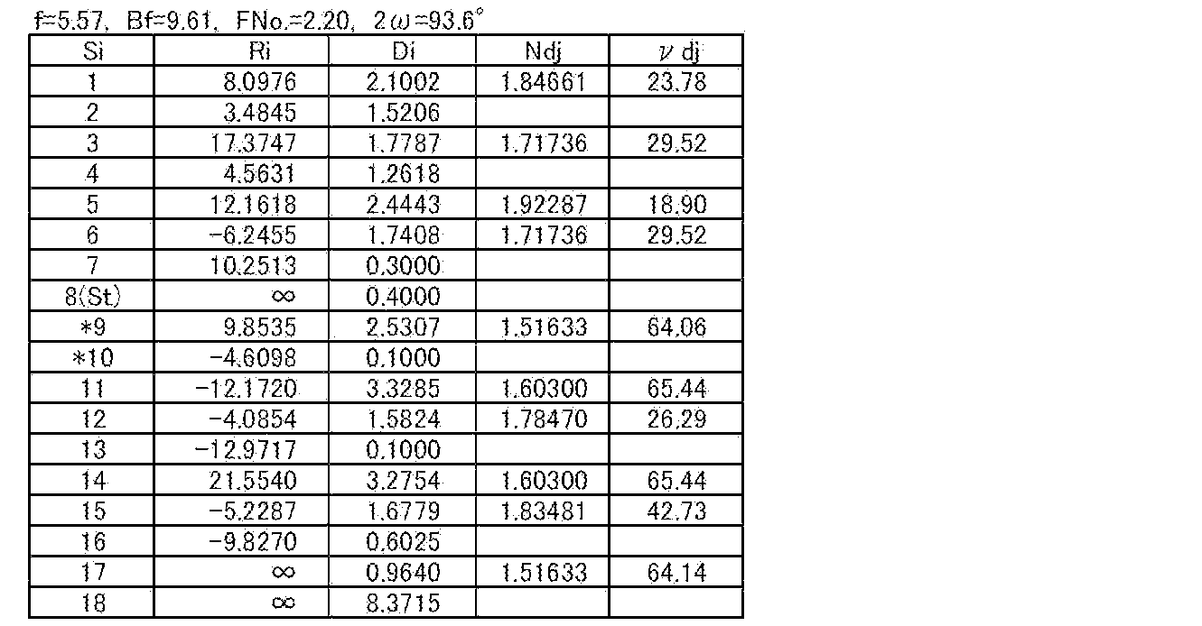

実施例3の撮像レンズの構成を示す断面図を図4に示す。実施例3の撮像レンズの群構成、概略構成は、上で述べた実施例2のものと同様である。表5、表6にそれぞれ実施例3の撮像レンズの基本レンズデータ、非球面係数を示す。図8(A)~図8(D)に実施例3の撮像レンズの各収差図を示す。
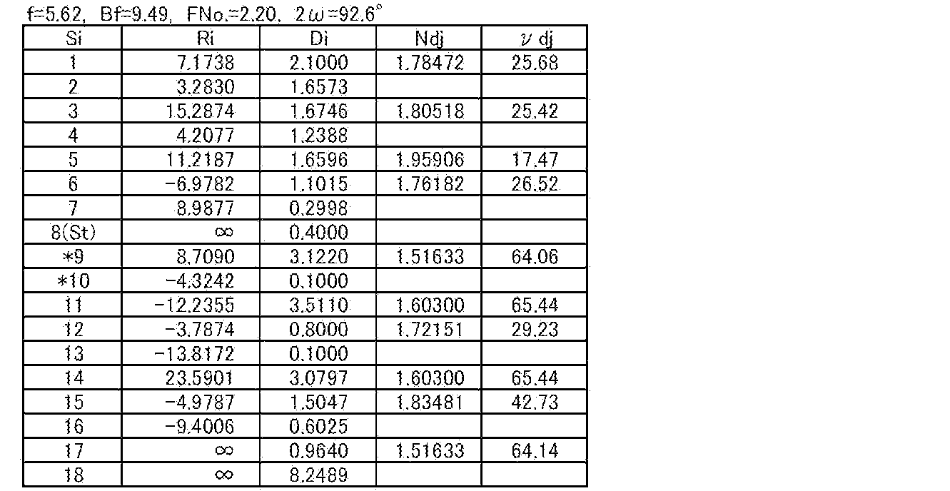

実施例4の撮像レンズの構成を示す断面図を図5に示す。実施例4の撮像レンズの群構成、概略構成は、前群正レンズ群GaPが、物体側から順に、正のレンズLa3と、負のレンズLa4と、正のレンズLa5とからなる点以外は、上で述べた実施例1のものと同様である。表7、表8にそれぞれ実施例4の撮像レンズの基本レンズデータ、非球面係数を示す。図9(A)~図9(D)に実施例4の撮像レンズの各収差図を示す。



Claims (14)
- 物体側から順に、負の屈折力を有する前群と、絞りと、正の屈折力を有する後群とから実質的に構成され、
前記前群が、物体側から順に、2枚以上の負レンズからなり負の屈折力を有する前群負レンズ群と、1枚の負レンズおよび1枚の正レンズを含み最も物体側に正レンズが配置されて正の屈折力を有する前群正レンズ群とから構成され、
前記後群が1枚の負レンズおよび1枚の正レンズを含み、
前記前群正レンズ群の最も像側の負レンズのd線に対する屈折率、d線に対するアッベ数をそれぞれNan、νanとしたとき、下記条件式(1)を満足する撮像レンズ。
Nan+0.01×νan<2.15 … (1) - 前記前群負レンズ群の焦点距離をfaNとし、全系の焦点距離をfとしたとき、下記条件式(2)を満足する請求項1記載の撮像レンズ。
-1.0<faN/f<-0.5 … (2) - 前記前群と前記後群との光軸上の空気間隔をDabとし、全系の焦点距離をfとしたとき、下記条件式(3)を満足する請求項1または2記載の撮像レンズ。
0.05<Dab/f<1.55 … (3) - 前記後群の最も物体側の正レンズのd線に対するアッベ数をνbpとしたとき、下記条件式(4)を満足する請求項1から3のいずれか1項記載の撮像レンズ。
νbp>55 … (4) - 前記前群負レンズ群が、2枚の物体側に凸面を向けた負メニスカスレンズから実質的に構成される請求項1から4のいずれか1項記載の撮像レンズ。
- 前記後群が、正レンズと負レンズが接合された接合レンズを2組含む請求項1から5のいずれか1項記載の撮像レンズ。
- 前記2組の接合レンズの接合面はともに物体側に凹面を向けている請求項6記載の撮像レンズ。
- 前記後群が、物体側から順に、正レンズと、正レンズおよび負レンズの接合レンズと、正レンズおよび負レンズの接合レンズとから実質的に構成される請求項1から7のいずれか1項記載の撮像レンズ。
- 下記条件式(1’)を満足する請求項1から8のいずれか1項記載の撮像レンズ。
Nan+0.01×νan<2.05 … (1’) - 前記前群負レンズ群の焦点距離をfaNとし、全系の焦点距離をfとしたとき、下記条件式(2’)を満足する請求項1から9のいずれか1項記載の撮像レンズ。
-0.9<faN/f<-0.6 … (2’) - 前記前群と前記後群との光軸上の空気間隔をDabとし、全系の焦点距離をfとしたとき、下記条件式(3’)を満足する請求項1から10のいずれか1項記載の撮像レンズ。
0.10<Dab/f<1.00 … (3’) - 下記条件式(3’’)を満足する請求項11記載の撮像レンズ。
0.10<Dab/f<0.55 … (3’’) - 前記後群の最も物体側の正レンズのd線に対するアッベ数をνbpとしたとき、下記条件式(4’)を満足する請求項1から11のいずれか1項記載の撮像レンズ。
νbp>60 … (4’) - 請求項1から13のいずれか1項記載の撮像レンズを備えた撮像装置。
Priority Applications (3)
| Application Number | Priority Date | Filing Date | Title |
|---|---|---|---|
| JP2015507696A JP5860567B2 (ja) | 2013-03-27 | 2013-12-26 | 撮像レンズおよびこれを備えた撮像装置 |
| CN201380074869.4A CN105143947B (zh) | 2013-03-27 | 2013-12-26 | 摄像透镜以及具备该摄像透镜的摄像装置 |
| US14/864,260 US9709778B2 (en) | 2013-03-27 | 2015-09-24 | Imaging lens and imaging apparatus equipped with the imaging lens |
Applications Claiming Priority (2)
| Application Number | Priority Date | Filing Date | Title |
|---|---|---|---|
| JP2013065915 | 2013-03-27 | ||
| JP2013-065915 | 2013-03-27 |
Related Child Applications (1)
| Application Number | Title | Priority Date | Filing Date |
|---|---|---|---|
| US14/864,260 Continuation US9709778B2 (en) | 2013-03-27 | 2015-09-24 | Imaging lens and imaging apparatus equipped with the imaging lens |
Publications (1)
| Publication Number | Publication Date |
|---|---|
| WO2014155462A1 true WO2014155462A1 (ja) | 2014-10-02 |
Family
ID=51622561
Family Applications (1)
| Application Number | Title | Priority Date | Filing Date |
|---|---|---|---|
| PCT/JP2013/007606 Ceased WO2014155462A1 (ja) | 2013-03-27 | 2013-12-26 | 撮像レンズおよびこれを備えた撮像装置 |
Country Status (4)
| Country | Link |
|---|---|
| US (1) | US9709778B2 (ja) |
| JP (1) | JP5860567B2 (ja) |
| CN (1) | CN105143947B (ja) |
| WO (1) | WO2014155462A1 (ja) |
Families Citing this family (4)
| Publication number | Priority date | Publication date | Assignee | Title |
|---|---|---|---|---|
| JP6452643B2 (ja) * | 2016-05-13 | 2019-01-16 | カンタツ株式会社 | 撮像レンズ |
| JP7141018B2 (ja) * | 2018-10-12 | 2022-09-22 | コニカミノルタ株式会社 | 光学系、レンズユニット、及び撮像装置 |
| CN113640972B (zh) * | 2021-08-10 | 2024-12-31 | 腾龙光学(佛山)有限公司 | 一种小型化高解像力定焦光学系统及图像拾取装置 |
| CN116184630B (zh) * | 2023-02-16 | 2025-10-17 | 桂林电子科技大学 | 视讯会议镜头 |
Citations (8)
| Publication number | Priority date | Publication date | Assignee | Title |
|---|---|---|---|---|
| JPS61200520A (ja) * | 1985-02-28 | 1986-09-05 | Canon Inc | バツクフオ−カスの長い広角レンズ |
| JPH02248910A (ja) * | 1989-03-23 | 1990-10-04 | Sigma:Kk | 魚眼レンズ |
| JPH05273459A (ja) * | 1992-03-26 | 1993-10-22 | Nikon Corp | 近距離補正機能を備えた魚眼レンズ |
| JPH0763989A (ja) * | 1993-06-16 | 1995-03-10 | Asahi Optical Co Ltd | 大口径非球面レンズ系 |
| JPH0996759A (ja) * | 1995-09-28 | 1997-04-08 | Fuji Photo Optical Co Ltd | レトロフォーカス型レンズ |
| JPH09127412A (ja) * | 1995-08-25 | 1997-05-16 | Asahi Optical Co Ltd | 大口径広角レンズ系 |
| JP2010191069A (ja) * | 2009-02-17 | 2010-09-02 | Canon Inc | 光学系及びそれを有する撮像装置 |
| JP2013130669A (ja) * | 2011-12-21 | 2013-07-04 | Olympus Imaging Corp | インナーフォーカスレンズ系及びそれを備えた撮像装置 |
Family Cites Families (9)
| Publication number | Priority date | Publication date | Assignee | Title |
|---|---|---|---|---|
| US5513045A (en) | 1993-06-16 | 1996-04-30 | Asahi Kogaku Kogyo Kabushiki Kaisha | Fast aspherical lens system |
| US5684643A (en) | 1995-08-25 | 1997-11-04 | Asahi Kogaku Kogyo Kabushiki Kaisha | Fast wide-angle lens system |
| JP3368138B2 (ja) | 1996-02-09 | 2003-01-20 | キヤノン株式会社 | レトロフォーカス型レンズ |
| JP4007468B2 (ja) | 1998-07-23 | 2007-11-14 | フジノン株式会社 | バックフォーカスの長い広角レンズ |
| US6844991B2 (en) * | 2002-08-01 | 2005-01-18 | Nikon Corporation | Fisheye lens |
| JP5095313B2 (ja) | 2007-08-31 | 2012-12-12 | 株式会社シグマ | 魚眼レンズ |
| JP2010243711A (ja) * | 2009-04-03 | 2010-10-28 | Ricoh Co Ltd | 広角レンズ及び撮像装置 |
| EP2397880B1 (en) * | 2010-06-16 | 2017-04-12 | Ricoh Company, Ltd. | Image-forming lens, and camera device and portable information terminal device with the image-forming lens |
| TWI414841B (zh) * | 2011-02-18 | 2013-11-11 | Largan Precision Co Ltd | 廣視角光學系統 |
-
2013
- 2013-12-26 CN CN201380074869.4A patent/CN105143947B/zh active Active
- 2013-12-26 WO PCT/JP2013/007606 patent/WO2014155462A1/ja not_active Ceased
- 2013-12-26 JP JP2015507696A patent/JP5860567B2/ja active Active
-
2015
- 2015-09-24 US US14/864,260 patent/US9709778B2/en active Active
Patent Citations (8)
| Publication number | Priority date | Publication date | Assignee | Title |
|---|---|---|---|---|
| JPS61200520A (ja) * | 1985-02-28 | 1986-09-05 | Canon Inc | バツクフオ−カスの長い広角レンズ |
| JPH02248910A (ja) * | 1989-03-23 | 1990-10-04 | Sigma:Kk | 魚眼レンズ |
| JPH05273459A (ja) * | 1992-03-26 | 1993-10-22 | Nikon Corp | 近距離補正機能を備えた魚眼レンズ |
| JPH0763989A (ja) * | 1993-06-16 | 1995-03-10 | Asahi Optical Co Ltd | 大口径非球面レンズ系 |
| JPH09127412A (ja) * | 1995-08-25 | 1997-05-16 | Asahi Optical Co Ltd | 大口径広角レンズ系 |
| JPH0996759A (ja) * | 1995-09-28 | 1997-04-08 | Fuji Photo Optical Co Ltd | レトロフォーカス型レンズ |
| JP2010191069A (ja) * | 2009-02-17 | 2010-09-02 | Canon Inc | 光学系及びそれを有する撮像装置 |
| JP2013130669A (ja) * | 2011-12-21 | 2013-07-04 | Olympus Imaging Corp | インナーフォーカスレンズ系及びそれを備えた撮像装置 |
Also Published As
| Publication number | Publication date |
|---|---|
| US9709778B2 (en) | 2017-07-18 |
| CN105143947A (zh) | 2015-12-09 |
| JP5860567B2 (ja) | 2016-02-16 |
| JPWO2014155462A1 (ja) | 2017-02-16 |
| CN105143947B (zh) | 2017-07-21 |
| US20160011407A1 (en) | 2016-01-14 |
Similar Documents
| Publication | Publication Date | Title |
|---|---|---|
| JP6309478B2 (ja) | 撮像レンズおよび撮像装置 | |
| JP6204896B2 (ja) | 撮像レンズおよび撮像装置 | |
| JP5749865B2 (ja) | 撮像レンズおよび撮像装置 | |
| JP6219176B2 (ja) | 撮像レンズおよび撮像装置 | |
| JP5795692B2 (ja) | 撮像レンズおよびこれを備えた撮像装置 | |
| JP6219189B2 (ja) | テレコンバーターレンズおよび撮像装置 | |
| WO2013153792A1 (ja) | 撮像レンズおよび撮像装置 | |
| JP6046565B2 (ja) | 撮像レンズおよび撮像装置 | |
| JP6204852B2 (ja) | ズームレンズおよび撮像装置 | |
| JP5749866B2 (ja) | 広角レンズおよび撮像装置 | |
| JP2015138174A (ja) | 撮像レンズ | |
| JP5633892B2 (ja) | 撮像レンズおよびこれを備えた撮像装置 | |
| US9477081B2 (en) | Imaging lens and imaging apparatus | |
| JP5860567B2 (ja) | 撮像レンズおよびこれを備えた撮像装置 | |
| JP2008116794A (ja) | 撮像レンズ | |
| WO2013018321A1 (ja) | 撮像レンズおよび撮像装置 |
Legal Events
| Date | Code | Title | Description |
|---|---|---|---|
| WWE | Wipo information: entry into national phase |
Ref document number: 201380074869.4 Country of ref document: CN |
|
| 121 | Ep: the epo has been informed by wipo that ep was designated in this application |
Ref document number: 13879938 Country of ref document: EP Kind code of ref document: A1 |
|
| ENP | Entry into the national phase |
Ref document number: 2015507696 Country of ref document: JP Kind code of ref document: A |
|
| NENP | Non-entry into the national phase |
Ref country code: DE |
|
| 122 | Ep: pct application non-entry in european phase |
Ref document number: 13879938 Country of ref document: EP Kind code of ref document: A1 |