WO2014148260A1 - タイヤ - Google Patents
タイヤ Download PDFInfo
- Publication number
- WO2014148260A1 WO2014148260A1 PCT/JP2014/055642 JP2014055642W WO2014148260A1 WO 2014148260 A1 WO2014148260 A1 WO 2014148260A1 JP 2014055642 W JP2014055642 W JP 2014055642W WO 2014148260 A1 WO2014148260 A1 WO 2014148260A1
- Authority
- WO
- WIPO (PCT)
- Prior art keywords
- tire
- width direction
- land
- block
- curvature
- Prior art date
Links
Images


Classifications
-
- B—PERFORMING OPERATIONS; TRANSPORTING
- B60—VEHICLES IN GENERAL
- B60C—VEHICLE TYRES; TYRE INFLATION; TYRE CHANGING; CONNECTING VALVES TO INFLATABLE ELASTIC BODIES IN GENERAL; DEVICES OR ARRANGEMENTS RELATED TO TYRES
- B60C11/00—Tyre tread bands; Tread patterns; Anti-skid inserts
- B60C11/03—Tread patterns
- B60C11/0306—Patterns comprising block rows or discontinuous ribs
-
- B—PERFORMING OPERATIONS; TRANSPORTING
- B60—VEHICLES IN GENERAL
- B60C—VEHICLE TYRES; TYRE INFLATION; TYRE CHANGING; CONNECTING VALVES TO INFLATABLE ELASTIC BODIES IN GENERAL; DEVICES OR ARRANGEMENTS RELATED TO TYRES
- B60C11/00—Tyre tread bands; Tread patterns; Anti-skid inserts
- B60C11/03—Tread patterns
- B60C11/11—Tread patterns in which the raised area of the pattern consists only of isolated elements, e.g. blocks
-
- B—PERFORMING OPERATIONS; TRANSPORTING
- B60—VEHICLES IN GENERAL
- B60C—VEHICLE TYRES; TYRE INFLATION; TYRE CHANGING; CONNECTING VALVES TO INFLATABLE ELASTIC BODIES IN GENERAL; DEVICES OR ARRANGEMENTS RELATED TO TYRES
- B60C11/00—Tyre tread bands; Tread patterns; Anti-skid inserts
- B60C11/03—Tread patterns
- B60C11/0327—Tread patterns characterised by special properties of the tread pattern
- B60C11/0332—Tread patterns characterised by special properties of the tread pattern by the footprint-ground contacting area of the tyre tread
-
- B—PERFORMING OPERATIONS; TRANSPORTING
- B60—VEHICLES IN GENERAL
- B60C—VEHICLE TYRES; TYRE INFLATION; TYRE CHANGING; CONNECTING VALVES TO INFLATABLE ELASTIC BODIES IN GENERAL; DEVICES OR ARRANGEMENTS RELATED TO TYRES
- B60C11/00—Tyre tread bands; Tread patterns; Anti-skid inserts
- B60C11/03—Tread patterns
- B60C11/13—Tread patterns characterised by the groove cross-section, e.g. for buttressing or preventing stone-trapping
- B60C11/1353—Tread patterns characterised by the groove cross-section, e.g. for buttressing or preventing stone-trapping with special features of the groove bottom
-
- B—PERFORMING OPERATIONS; TRANSPORTING
- B60—VEHICLES IN GENERAL
- B60C—VEHICLE TYRES; TYRE INFLATION; TYRE CHANGING; CONNECTING VALVES TO INFLATABLE ELASTIC BODIES IN GENERAL; DEVICES OR ARRANGEMENTS RELATED TO TYRES
- B60C11/00—Tyre tread bands; Tread patterns; Anti-skid inserts
- B60C11/03—Tread patterns
- B60C11/13—Tread patterns characterised by the groove cross-section, e.g. for buttressing or preventing stone-trapping
- B60C11/1369—Tie bars for linking block elements and bridging the groove
-
- B—PERFORMING OPERATIONS; TRANSPORTING
- B60—VEHICLES IN GENERAL
- B60C—VEHICLE TYRES; TYRE INFLATION; TYRE CHANGING; CONNECTING VALVES TO INFLATABLE ELASTIC BODIES IN GENERAL; DEVICES OR ARRANGEMENTS RELATED TO TYRES
- B60C11/00—Tyre tread bands; Tread patterns; Anti-skid inserts
- B60C11/03—Tread patterns
- B60C11/13—Tread patterns characterised by the groove cross-section, e.g. for buttressing or preventing stone-trapping
- B60C11/1376—Three dimensional block surfaces departing from the enveloping tread contour
-
- B—PERFORMING OPERATIONS; TRANSPORTING
- B60—VEHICLES IN GENERAL
- B60C—VEHICLE TYRES; TYRE INFLATION; TYRE CHANGING; CONNECTING VALVES TO INFLATABLE ELASTIC BODIES IN GENERAL; DEVICES OR ARRANGEMENTS RELATED TO TYRES
- B60C11/00—Tyre tread bands; Tread patterns; Anti-skid inserts
- B60C11/03—Tread patterns
- B60C11/13—Tread patterns characterised by the groove cross-section, e.g. for buttressing or preventing stone-trapping
- B60C11/1353—Tread patterns characterised by the groove cross-section, e.g. for buttressing or preventing stone-trapping with special features of the groove bottom
- B60C2011/1361—Tread patterns characterised by the groove cross-section, e.g. for buttressing or preventing stone-trapping with special features of the groove bottom with protrusions extending from the groove bottom
Definitions
- the present invention relates to a tire having a land portion formed in a tread portion.
- Patent Document 1 a tire having a flat table portion and a peripheral portion surrounding the table portion in the land portion block is known (see Patent Document 1).
- the present invention has been made in view of the above-described conventional problems, and an object of the present invention is to improve the exercise performance on a dry road surface of a tire provided with a land portion, and increase the drainage performance of the land portion to increase the tire on a wet road surface. It is to improve the exercise performance.
- the present invention is a tire having a land portion formed in a tread portion. Further, the ground contact surface of the land portion is formed in a convex shape in which a plurality of curved portions having a predetermined curvature are smoothly connected at least in a cross section of the land portion in the tire width direction.
- Rc is the curvature of the central curved portion including the center portion of the ground plane and Re is the curvature of the end curved portion including the end portion of the ground plane.
- the curvature of the curved portion located between the central curved portion and the end curved portion is within the range of Rc to Re.
- the present invention it is possible to improve the kinematic performance on a dry road surface of a tire provided with a land portion, and to increase the drainage performance of the land portion, thereby improving the kinematic performance of a tire on a wet road surface.
- the tire of this embodiment is a pneumatic tire for vehicles (for example, for passenger cars), and is formed in a well-known structure with a general tire constituent member. That is, the tire includes a pair of bead portions, a tread portion, and a pair of sidewall portions positioned between the bead portion and the tread portion.
- the tire includes a pair of bead cores, a carcass disposed between the pair of bead cores, a belt disposed on the outer peripheral side of the carcass, and a tread rubber having a predetermined tread pattern.
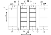
- FIG. 1 is a plan view showing a tread pattern of the tire 1 of the first embodiment, and schematically shows a part of the tire circumferential direction S of the tread portion 2. As illustrated, the tread portion 2 of the tire 1 is formed symmetrically with respect to the center line CL in the tire width direction H.
- the tire 1 also includes a plurality of circumferential grooves 10 to 12, a plurality of land portions 20 to 23, and a plurality of widthwise grooves 13 and 14 formed in the tread portion 2. A plurality (three in FIG.
- circumferential grooves 10 to 12 are main grooves extending in the tire circumferential direction S, and the central circumferential groove 10 located on the center line CL and the tire circumferential direction of the central circumferential groove 10 It consists of two outer circumferential grooves 11 and 12 located outside H.
- the tread portion 2 is partitioned in the tire width direction H by the plurality of circumferential grooves 10 to 12, and a plurality (four in FIG. 1) of land portions 20 to 23 are formed along the tire circumferential direction S.
- the land portions 20 to 23 are ribs (continuous land portions) continuously extending in the tire circumferential direction S, or block rows (intermittent land portions) including a plurality of blocks arranged in the tire circumferential direction S.
- the land portions 20 to 23 are block rows having a plurality of blocks 20A to 23A, and are composed of two central land portions 20 and 21 and two shoulder land portions 22 and 23.
- the tire 1 includes a plurality of blocks 20A to 23A in the tread portion 2 and the land portions 20 to 23.
- the central land portions 20 and 21 have a plurality of width direction grooves 13 and are formed on both sides of the center line CL of the tread portion 2.
- the shoulder land portions 22 and 23 have a plurality of width direction grooves 14 and are formed on the outer side (the shoulder portion side) of the central land portions 20 and 21 in the tire width direction H.
- the width direction grooves 13 and 14 are lateral grooves extending in the tire width direction H, and are formed in the land portions 20 to 23 along the tire width direction H so as to cross the land portions 20 to 23 in the tire width direction H.
- the land portions 20 to 23 are divided in the tire circumferential direction S by the plurality of widthwise grooves 13 and 14, and a plurality of blocks 20A to 23A are formed in the land portions 20 to 23.
- the blocks 20A to 23A are formed in the land portions 20 to 23 by the circumferential grooves 10 to 12 and the width direction grooves 13 and 14. Further, the blocks 20A to 23A are partitioned by the circumferential grooves 10 to 12 and the width direction grooves 13 and 14, and are formed in a rectangular shape (rectangular shape in FIG. 1) in the land portions 20 to 23 in plan view. Yes.
- the plurality of land portions 20 to 23 and the plurality of blocks 20A to 23A are formed on the ground contact surface of the tread portion 2. Further, the ground contact surfaces of the land portions 20 to 23 are formed in a convex shape at least in the cross section of the land portions 20 to 23 in the tire width direction H.
- the ground planes of the land portions 20 to 23 are the ground planes of the plurality of blocks 20A to 23A, respectively.
- the entire contact surfaces of the land portions 20 to 23 are each formed in a convex shape that rises outward in the tire radial direction.
- the ground contact surfaces of the land portions 20 to 23 are convex curved surfaces.
- a single land portion 20 (central land portion) is taken as an example, and the ground contact surface of the land portion 20 will be described in detail.
- FIG. 2 is a cross-sectional view of the land portion 20 in the tire width direction H.
- the ground contact surface 30 of the land portion 20 (block 20A) has a convex shape in which a plurality of curved portions (curved surface portions) 31 to 33 are smoothly connected in the cross section of the land portion 20 in the tire width direction H. Is formed. That is, the ground contact surface 30 is smoothly curved at the boundaries (shown by dotted lines in FIG. 2) of the plurality of curved portions 31 to 33, and the entire ground contact surface 30 is formed into a smoothly curved curved surface (convex curved surface). ing.
- the plurality of curved portions 31 to 33 each have a predetermined curvature Rc, Re, Rm and are formed in an arc shape.
- the ground contact surface 30 is composed of two or more (five in FIG. 2) curved portions 31 to 33, and the curvature of the ground contact surface 30 is between the end portions 34 of the ground contact surface 30 in the tire width direction H. Change.
- the convex shape of the ground contact surface 30 is a convex curve in which a plurality of curved portions 31 to 33 are smoothly connected in the cross section of the land portion 20 in the tire width direction H.
- the plurality of curved portions 31 to 33 are a central curved portion 31 including a center portion 35 in the tire width direction H of the ground contact surface 30 (land portion 20) and an end curved portion including an end portion 34 in the tire width direction H of the ground contact surface 30. 32 and an intermediate curve portion 33 located between the central curve portion 31 and the end curve portion 32.
- the curvature of the central curve portion 31 is Rc
- the curvature of the end curve portion 32 is Re
- the curvature of the intermediate curve portion 33 is Rm.
- Rc and Re satisfy the relationship (Rc ⁇ Re), and Re is larger than Rc.
- the curvature Rm of the intermediate curve portion 33 is in the range of Rc to Re, and the curvatures Rc, Re, and Rm of the plurality of curve portions 31 to 33 are gradually increased from the central curve portion 31 toward the end curve portion 32. Become.
- the center curve part 31 is formed in the center area
- the end curve portion 32 is formed in the end region of the land portion 20 in the tire width direction H, and the curvature Re is the curvature of the ground contact surface 30 in the end region.
- the intermediate curved portion 33 is formed in the intermediate region of the land portion 20 located between the central region and the end region, and the curvature Rm is the curvature of the ground contact surface 30 in the intermediate region.
- the center portion 35 of the ground contact surface 30 is the top of the ground contact surface 30 that protrudes most outward in the tire radial direction.
- the ground contact surface 30 is formed in a convex shape in which the plurality of curved portions 31 to 33 are smoothly connected, and the curvatures Rc, Re, and Rm are the central curved portions. It gradually increases from 31 toward the end curve portion 32.
- the ground pressure of the land portion 20 increases on the center portion 35 side of the ground surface 30 and gradually decreases toward the end portion 34 of the ground surface 30. Accordingly, local deformation of the tread rubber at the end portion 34 is suppressed, and slippage between the road surface and the tread rubber is reduced.
- the contact area of the land portion 20 can be sufficiently secured, the exercise performance of the tire 1 on the dry road surface can be improved.
- the convex ground contact surface 30 can efficiently drain the water on the ground contact surface 30 around the land portion 20.
- the plurality of curved portions 31 to 33 are smoothly connected, local deformation of the tread rubber in the ground contact surface 30 and an increase in the contact pressure can be prevented.
- water can be smoothly discharged from the ground contact surface 30 around the land portion 20, and the water between the ground contact surface 30 and the road surface can be reliably removed.
- the curvature Rc of the central curved portion 31 is preferably in the range of 2.5 to 5 (1 / m), and the curvature Re of the end curved portion 32 is in the range of 50 to 200 (1 / m). Is preferred. Further, the ratio of Re to Rc (Re / Rc) is preferably in the range of 15 to 60, and more preferably in the range of 20 to 45. When the width in the tire width direction H of the land portion 20 is W and the width in the tire width direction H of the end curve portion 32 is We, the ratio of We to W (We / W) is 0.05 to 0.2. It is preferable to be within the range. By doing so, Rc, Re, Re / Rc, and We / W can be optimized respectively.
- the ground contact area of the land portion 20 may be reduced without grounding to the end of the land portion 20.
- a corner portion (edge portion) is formed at the end portion of the land portion 20 by the ground surface 30 and the side wall without smoothly connecting the ground surface 30 and the side wall of the land portion 20.
- the ground contact surfaces of one or more land portions 20 to 23 into convex ground contact surfaces 30.
- the ground contact surfaces of all the land portions 20 to 23 may be convex ground surfaces 30, and the ground surfaces of one or more land portions 20 to 23 may be convex ground surfaces 30.
- the ground contact surface 30 may be formed in a convex shape only in the cross section in the tire width direction H of the blocks 20A to 23A.
- the ground plane 30 may be formed in a convex shape in cross sections in all directions passing through the centers of the blocks 20A to 23A.
- the ground contact surface 30 is formed in a convex shape only in the cross section in the tire width direction H.
- the present invention may be applied only to the inner portion in the tire width direction H.
- Two or more curved portions may be provided between the central curved portion 31 and the end curved portion 32 of the ground plane 30.
- the present invention has been described by taking a pneumatic tire as an example, but the present invention can also be applied to a tire filled with a gas other than air and other tires. Further, the tread portion 2 may be formed with sipes or grooves other than those described above.
- Each tire is a passenger car tire and was manufactured under the following conditions.
- Width direction grooves 13 of the central land portions 20 and 21 width 1 mm in the tire circumferential direction S, depth 7 mm, 140 pieces spaced apart in the tire circumferential direction S
- Width direction grooves 14 of the shoulder land portions 22 and 23 tire circumferential direction 70 pieces with a width of S of 4 mm, a depth of 7 mm, and an interval in the tire circumferential direction S.
- Each tire was formed such that only the ground contact surfaces of the two central land portions 20 and 21 were different.
- FIG. 3 is a diagram showing a land portion (block) 40 of a conventional product, and shows one block.
- 3A is a perspective view of the land portion 40
- FIG. 3B is a cross-sectional view of the land portion 40.
- the conventional land portion 40 has a planar table portion 41 and a peripheral portion 42 surrounding the table portion 41.
- the peripheral part 42 consists of a curved surface formed between the table part 41 and the end part of the land part 40.
- the ground contact surface 43 of the land portion 40 is formed in a convex shape in which a portion of the table portion 41 forms a planar shape.
- the ratio of m to M (m / M) is 0.5.
- the width of the table portion 41 in the tire circumferential direction S is l and the width of the land portion 40 in the tire circumferential direction S is L, the ratio of l to L (l / L) is 0.5.
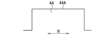
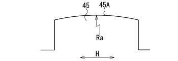
- FIG. 4 to 6 are cross-sectional views showing the land portions 44, 45, and 46 of the comparative products 1 to 3, and show cross sections in the tire width direction H.
- FIG. 4 In the comparative product 1, as shown in FIG. 4, the ground contact surface 44A of the land portion 44 is formed in a flat shape.
- the ground contact surface 45 ⁇ / b> A of the land portion 45 is formed with a single curvature Ra.
- the curvature Ra is 3.3 (1 / m).
- the ground contact surface 46A of the land portion 46 is formed in a flat shape. However, only a part of the end face side of the grounding surface 46A was formed with the curvature Rb.
- the curvature Rb is 100 (1 / m).
- the width Ne of the Rb portion in the tire width direction H is 2 mm, which is 8% of the width N of the land portion 46 in the tire width direction H.
- the curvature Rc of the central curved portion 31 is 3.3 (1 / m)
- the curvature Re of the end curved portion 32 is 100 (1 / m).
- the ratio of We to W (We / W) is 0.08, and We is 8% of W. Further, We is 2 mm.
- each tire was assembled to a rim (6J15), and the internal pressure was adjusted to 180 kPa.
- driving on a test course with a vehicle equipped with each tire, and driver's sensory evaluation steering stability performance on dry road surface (dry steering stability performance) and steering stability performance on wet road surface (water depth 1mm) (wet steering stability) Performance).
- dry steering stability performance dry road surface
- wet steering stability performance wet road surface
- water depth 10 mm wet steering stability
- Table 1 shows the evaluation results.
- the evaluation results are expressed as an index with the conventional product as 100, and the larger the value, the higher the performance.
- the higher the dry steering stability performance the higher the motion performance (dry performance) of the tire on the dry road surface.
- the higher the wet steering stability performance and the larger the hydroplaning generation speed the higher the motion performance (wet performance) of the tire on the wet road surface.
- the hydroplaning generation speed the speed increases as the numerical value increases. As the numerical value increases, hydroplaning is less likely to occur.
- each performance of the conventional product was higher than that of the comparative product 1, and the wet performance of the conventional product was greatly improved over the dry performance based on the comparative product 1.
- the wet performance is higher than that of the conventional product.
- the dry performance is higher than that of the comparative product 2.
- Comparative Product 3 the dry performance was higher than that of the conventional product, but the wet performance was lower than that of the conventional product. This is because local deformation of the tread rubber occurs in the ground contact surface 46A.
- the factors that increase each performance are synergistic, and the factors that lower each performance are offset, and both the dry performance and the wet performance are improved.
- Table 2 shows the evaluation results when the curvature Rc of the central curved portion 31 is changed.
- Table 2 in addition to the evaluation results of the implementation product A described above, the evaluation results of 6 implementation products 1-1 to 1-6 having different Rc are shown.
- Table 2 (the same applies to Tables 3 and 4 below), the ratio of We to W (We / W) is expressed as% by multiplying We / W by 100.
- the curvature Rc of the central curved portion 31 is in the range of 2.5 to 5 (1 / m)
- the dry performance and the wet performance become higher and are surely improved.
- the performance of the implementation product A is the highest, and the conditions of the implementation product A are optimal.
- Table 3 shows the evaluation results when the curvature Re of the end curve portion 32 is changed.
- Table 3 shows the evaluation results of the six execution products 2-1 to 2-6 having different Re in addition to the evaluation result of the execution product A described above.
- the curvature Re of the end curve portion 32 is in the range of 50 to 200 (1 / m)
- the dry performance and the wet performance become higher and are surely improved.
- the performance of the implementation product A is the highest, and the conditions of the implementation product A are optimal.
- Table 4 shows the evaluation results when We / W was changed.
- Table 3 shows the evaluation results of the six implementation products 3-1 to 3-6 having different We / Ws in addition to the evaluation results of the implementation product A described above.
- We is 5 to 20% of W, that is, when We / W is in the range of 0.05 to 0.2, dry performance and wet performance become higher, Will definitely improve.
- the performance of the implementation product A is the highest, and the conditions of the implementation product A are optimal.
- the tire of the second embodiment basically has the same configuration as that of the tire 1 of the first embodiment, and exhibits the same effects as the tire 1 of the first embodiment.
- the same name as the structure of the tire 1 is used for the structure corresponding to the structure of the tire 1 of the first embodiment.
- FIG. 7 is a plan view showing a tread pattern of the tire 51 of the second embodiment, and schematically shows a part of the tread portion 52 in the tire circumferential direction S.
- the tread portion 52 of the tire 51 is formed symmetrically with respect to the center line CL in the tire width direction H.
- the tire 51 includes a plurality of circumferential grooves 60 to 62, a plurality of width grooves 63 and 64, a plurality of land portions 70 to 73, and a plurality of land portions 70 to 73 formed in the tread portion 52.
- Blocks 70A to 73A Blocks 70A to 73A.
- a plurality (three in FIG. 7) of circumferential grooves 60 to 62 are main grooves extending in the tire circumferential direction S, and the central circumferential groove 60 located on the center line CL and the tire circumferential direction of the central circumferential groove 60 It consists of two outer circumferential grooves 61 and 62 located outside H.
- the tread portion 52 is partitioned in the tire width direction H by the plurality of circumferential grooves 60 to 62, and a plurality (four in FIG. 7) of land portions 70 to 73 are formed along the tire circumferential direction S.
- the land portions 70 to 73 are block rows (intermittent land portions) composed of a plurality of blocks 70A to 73A arranged in the tire circumferential direction S, and each have a plurality of blocks 70A to 73A.
- the land portions 70 to 73 include two central land portions 70 and 71 and two shoulder land portions 72 and 73.
- the central land portions 70 and 71 have a plurality of width direction grooves 63 and are formed on both sides of the center line CL of the tread portion 52.
- the shoulder land portions 72 and 73 have a plurality of width direction grooves 64 and are formed outside the center land portions 70 and 71 in the tire width direction H (the shoulder portion side).
- the width direction grooves 63 and 64 are lateral grooves extending in the tire width direction H, and are formed in the land portions 70 to 73 along the tire width direction H so as to cross the land portions 70 to 73 in the tire width direction H.
- the land portions 70 to 73 are divided in the tire circumferential direction S by the plurality of widthwise grooves 63 and 64, and a plurality of blocks 70 A to 73 A are formed in the land portions 70 to 73.
- the blocks 70A to 73A are formed in the land portions 70 to 73 by circumferential grooves 60 to 62 and width direction grooves 63, 64.
- the blocks 70A to 73A are partitioned by circumferential grooves 60 to 62 and width direction grooves 63 and 64, and are formed in the land portions 70 to 73 in a rectangular shape (rectangular shape in FIG. 7) in plan view. Yes.
- the plurality of land portions 70 to 73 and the plurality of blocks 70A to 73A are formed on the ground contact surface of the tread portion 52.
- the contact surfaces of the land portions 70 to 73 are the contact surfaces of the plurality of blocks 70A to 73A, respectively.
- the contact surfaces of the blocks 70A to 73A are formed in a convex shape in the cross section of the blocks 70A to 73A in the tire width direction H. Yes. Further, the contact surfaces of the blocks 70A to 73A are formed in a flat shape in the cross section of the blocks 70A to 73A in the tire circumferential direction S.
- the entire contact surfaces of the blocks 70A to 73A are formed in a convex shape that rises outward in the tire radial direction.
- the ground contact surfaces of the blocks 70A to 73A are convex curved surfaces.
- Each block 70A to 73A has a pair of width direction edges formed by a pair of width direction grooves 63 and 64.
- the depth of the widthwise grooves 63 and 64 (the depth in the tire radial direction) is more central than both ends of the widthwise edges. It is shallow in the department.
- the grounding surface of the block 70A and the width direction groove 63 will be described in detail.
- FIG. 8 is a perspective view of one block 70 ⁇ / b> A defined by the circumferential grooves 60 and 61 and the width direction groove 63.
- the width direction edge portion 80 is an edge portion extending in the tire width direction H of the block 70A, and is formed at the end portion (both ends) of the block 70A in the tire circumferential direction S by the width direction groove 63. Yes.
- the depth of the width direction groove 63 is larger than both end portions 81 of the width direction edge 80. It becomes shallow at the central part 82 of the edge 80 in the width direction.
- An end portion 81 of the width direction edge portion 80 is an end portion of the width direction edge portion 80 in the tire width direction H, and a center portion 82 of the width direction edge portion 80 is a center of the width direction edge portion 80 in the tire width direction H. Part.
- the convex portion 65 is formed in the width direction groove 63 and protrudes from the bottom of the width direction groove 63 toward the outer side in the tire radial direction.
- the convex portion 65 has a rectangular parallelepiped shape, is located at the center portion 82 of the width direction edge portion 80, and is integrally formed on the side walls of the two blocks 70A adjacent to the tire circumferential direction S.
- at least one (at least one) width direction groove 63 has a convex portion 65, and the convex portion 65 causes at least one width direction groove 63 to be larger than both end portions 81 of the width direction edge 80. It is formed so as to be shallow at the central portion 82. Further, the depth of the width direction groove 63 is discontinuously changed by the convex portion 65, and the depth of the width direction groove 63 at the center portion 82 becomes shallower than the depth of the width direction groove 63 at the both end portions 81. .
- the tire 51 includes corner portions 83 that extend in the tire circumferential direction S at the ends (both ends) in the tire width direction H of the block 70A.
- the corner 83 is an obtuse edge formed by the side wall 84 (wall surface of the circumferential grooves 60 and 61) of the block 70A and the grounding surface 90 of the block 70A, and between the side wall 84 and the grounding surface 90 of the block 70A. To position.
- the land portion 70 of the tire 51 is configured by a plurality of blocks 70A, and the ground contact surface 90 of the block 70A of the land portion 70 is formed in the same manner as the ground contact surface 30 of the land portion 20 (block 20A) of the first embodiment.
- the ground contact surface 90 of the block 70A is formed in a convex shape in which a plurality of curved portions (curved portions) 91 to 93 are smoothly connected in the cross section of the block 70A in the tire width direction H. That is, the grounding surface 90 is smoothly curved at the boundary between the plurality of curved portions 91 to 93 (a part of the boundary is shown by a dotted line in FIG.
- the entire grounding surface 90 is a curved surface (convex) that is smoothly curved. Curved surface).
- the plurality of curved portions 91 to 93 each have predetermined curvatures Rc, Re, and Rm, and are formed in an arc shape.
- the ground contact surface 90 is composed of two or more (five in FIG. 8) curved portions 91 to 93, and the curvature of the ground contact surface 90 is between the end portions 94 of the ground contact surface 90 in the tire width direction H. Change.
- the convex shape of the ground contact surface 90 is a convex curve in which a plurality of curved portions 91 to 93 are smoothly connected in the cross section of the block 70A in the tire width direction H.
- the plurality of curved portions 91 to 93 include a central curved portion 91 including a center portion 95 in the tire width direction H of the ground contact surface 90 (block 70A), and an end curved portion 92 including an end portion 94 in the tire width direction H of the ground contact surface 90. And an intermediate curve portion 93 located between the central curve portion 91 and the end curve portion 92.
- the curvature of the central curve portion 91 is Rc
- the curvature of the end curve portion 92 is Re
- the curvature of the intermediate curve portion 93 is Rm.
- Rc and Re satisfy the relationship (Rc ⁇ Re), and Re is larger than Rc.
- the curvature Rm of the intermediate curve portion 93 is in the range of Rc to Re, and the curvatures Rc, Re, Rm of the plurality of curve portions 91 to 93 are gradually increased from the central curve portion 91 toward the end curve portion 92. Become.
- the central curved portion 91 is formed in the central region in the tire width direction H of the block 70A (land portion 70), and the curvature Rc is the curvature of the ground contact surface 90 in the central region.
- the end curve portion 92 is formed in the end region in the tire width direction H of the block 70A, and the curvature Re is the curvature of the ground contact surface 90 in the end region.
- the intermediate curved portion 93 is formed in the intermediate region of the block 70A located between the central region and the end region, and the curvature Rm is the curvature of the ground contact surface 90 in the intermediate region.
- the center portion 95 of the ground contact surface 90 is the top of the ground contact surface 90 that protrudes most outward in the tire radial direction.
- the ground contact surface 90 of the block 70A (land portion 70) is formed in the same manner as the ground contact surface 30 of the land portion 20 in the tire 1 of the first embodiment. . Therefore, the tire 51 exhibits the same effect as the tire 1 of the first embodiment described above.
- the convex ground contact surface 90 allows the water on the ground contact surface 90 to be efficiently discharged around the block 70A, and sufficient drainage performance can be ensured for the block 70A. Further, the water between the ground contact surface 90 and the road surface can be removed smoothly, and the actual contact area of the block 70A on the wet road surface can be increased.
- the drainage performance of the block 70A can be increased, and the motion performance of the tire 51 on the wet road surface can be improved.
- the ground contact surface 90 in a convex shape, local deformation of rubber at the end 94 of the ground contact surface 90 is suppressed, and slippage between the road surface and the block 70A is reduced.
- each block 70A the depth of at least one width direction groove 63 is made shallower at the central portion 82 than the end portion 81 of the width direction edge 80. Thereby, the rigidity with respect to compression of the center part of block 70A becomes high, and a deformation
- a longitudinal or lateral force of the tire 51 is applied to the block 70A, the deformation of the block 70A is suppressed, and the ground contact performance and grip performance of the block 70A are enhanced. Therefore, the ground contact performance of the block 70A can be increased, and the motion performance of the tire 51 on the dry road surface can be improved.
- both the ground contact performance and the drainage performance of the block 70A can be enhanced, and the motion performance of the tire 51 on the dry road surface and the wet road surface can be further improved.
- the ground contact surface 90 having a convex shape increases the ground pressure of the block 70 ⁇ / b> A on the center portion 95 side of the ground surface 90 and gradually decreases toward the end portion 94 of the ground surface 90.
- the water on the ground contact surface 90 can be smoothly discharged around the block 70A, so that the drainage performance of the block 70A can be further enhanced.
- the contact area of the actual block 70A on the wet road surface can also be increased.
- the curvature Rc of the central curve portion 91 is preferably in the range of 2.5 to 5 (1 / m), and the curvature Re of the end curve portion 92 is 50 to It is preferable to be within the range of 200 (1 / m).
- the ratio of Re to Rc (Re / Rc) is preferably in the range of 15-60.
- the ratio of We to W is in the range of 0.05 to 0.2. It is preferable to be inside. By doing so, it is possible to optimize the We / W and to ensure a sufficient ground contact area in the block 70A while improving the drainage performance of the block 70A.
- the grounding area of the block 70A may be reduced without grounding to the end of the block 70A.
- the side wall 84 and the ground contact surface 90 of the block 70A are not smoothly connected, and the corner portion 83 is formed at the end in the tire width direction H of the block 70A by the side wall 84 and the ground contact surface 90. To do. As a result, the end of the block 70A is grounded, so that the grounding area of the block 70A can be ensured.
- each block 70A by changing the depth of at least one width direction groove 63 so as to be shallower at the center portion 82 than at the end portion 81, the above-described effect by the width direction groove 63 can be obtained. Therefore, the depth of both of the width direction grooves 63 of the pair of width direction grooves 63 that define each block 70A may be changed, or the depth of one of the width direction grooves 63 may be changed. . However, when the depths of both the width direction grooves 63 are changed, the above-described effect by the width direction grooves 63 can be further improved.
- the above-described effects of the tire 51 can be obtained by forming the blocks 70A to 73A of the one or more land portions 70 to 73 and the width direction grooves 63 and 64 as described above. Accordingly, the blocks 70A to 73A and the width direction grooves 63 and 64 of all the land portions 70 to 73 may be formed as described above, and the blocks 70A to 73A and the width direction grooves of one or more land portions 70 to 73 may be formed. 63 and 64 may be formed as described above. Further, the tread portion 52 may be formed with sipes or grooves other than those described above.
- Each tire is a passenger car tire and was manufactured under the following conditions. Size: 195 / 65R15 (JATMA YEAR BOOK (2013, Japan Automobile Tire Association Standard)) Circumferential groove: 3 (see FIG. 7), width 9 mm, depth 7.5 mm Arrangement of circumferential grooves: one central circumferential groove 60 on the center line CL in the tire width direction H, and two outer circumferential grooves 61 and 62 outside the tire width direction H of the central land portions 70 and 71 (width 25 mm).
- Width direction grooves 63 of the central land portions 70, 71 width 2mm in the tire circumferential direction S, depth 7.5mm, 140 spaced in the tire circumferential direction S
- width direction grooves 64 of the shoulder land portions 72, 73 tire 70 tires having a width of 4 mm in the circumferential direction S, a depth of 7.5 mm, and an interval in the tire circumferential direction S.
- Each tire was formed so that only the block of the two central land portions 70 and 71 and the width direction groove 63 were different. .
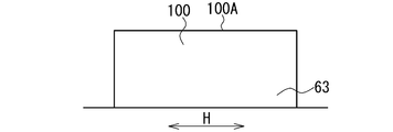
- FIG. 9 to 11 are front views showing the blocks 100, 101, and 110 of the central land portions 70 and 71 of the comparative products 4 to 6, and show the blocks 100, 101, and 110 viewed from the tire circumferential direction S.
- the ground contact surface 100A of the block 100 is formed in a planar shape.
- channel 63 is formed so that a depth may not change.
- the ground contact surface 101A of the block 101 is formed in a flat shape.
- the convex part 65 is formed in the width direction groove
- the height of the convex portion 65 in the tire radial direction is 3 mm, and the length of the convex portion 65 in the tire width direction H is 12 mm.
- the ground contact surface 111 of the block 110 is formed in a convex shape in which a plurality of curved portions having a predetermined curvature are smoothly connected in the cross section of the block 110 in the tire width direction H.
- the curvature Rg of the central curve portion 112 including the center portion of the ground surface 111 is 3.3 (1 / m)
- the curvature Rh of the end curve portion 113 including the end portion of the ground surface 111 is 100 (1 / m). is there.
- the width Qe of the end curve portion 113 in the tire width direction H is 2 mm, which is 8% of the width Q of the block 110 in the tire width direction H. Further, there is no convex portion 65 in the width direction groove 63.
- the blocks 70A and 71A of the implementation product B are formed in a shape in which the comparison product 5 and the comparison product 6 are combined. That is, the curvature Rc of the central curved portion 91 is 3.3 (1 / m), and the curvature Re of the end curved portion 92 is 100 (1 / m). Further, a convex portion 65 similar to that of the comparative product 5 is formed in the width direction groove 63. The ratio of We to W (We / W) is 0.08, and We is 8% of W. We is 2 mm.
- the conventional product has the same land portion (block) 40 as the conventional product (see FIG. 3) described in the first embodiment.
- each tire was assembled to a rim (6J15), and the internal pressure was adjusted to 180 kPa.
- driving on a test course with a vehicle equipped with each tire, and driver's sensory evaluation steering stability performance on dry road surface (dry steering stability performance) and steering stability performance on wet road surface (water depth 1mm) (wet steering stability) Performance).
- dry steering stability performance dry road surface
- wet steering stability performance wet road surface
- water depth 10 mm wet steering stability
- Table 5 shows the evaluation results.
- the evaluation results are expressed as an index with the conventional product as 100, and the larger the value, the higher the performance.
- Each performance of the conventional product was higher than that of the comparative product 4, and the wet performance of the conventional product was greatly improved over the dry performance based on the comparative product 4.
- the rigidity of the block 101 is increased, and the grounding performance of the block 101 is improved. Therefore, the dry performance is higher than that of the conventional product and the comparative product 4.
- the ground pressure at the center of the block 101 does not become higher than that of the conventional product, so the drainage performance and the wet performance are lower than the conventional product.
- the comparative product 6 since the water on the ground contact surface 111 can be efficiently discharged by the convex ground contact surface 111, the wet performance is higher than that of the conventional product.
- the dry performance is equivalent to the conventional product.
- the ground contact performance and the drainage performance can be improved by the convex ground contact surface 90 and the width direction groove 63, so that both the dry performance and the wet performance are improved.
- Table 6 shows the evaluation results when the curvature Rc of the central curved portion 91 is changed.
- Table 6 shows the evaluation results of the six execution products 4-1 to 4-6 having different Rc in addition to the evaluation result of the execution product B described above.
- the ratio of We to W (We / W) is expressed as% by multiplying We / W by 100.
- the curvature Rc of the central curved portion 91 is in the range of 2.5 to 5 (1 / m)
- the dry performance and the wet performance become higher and surely improve.
- the performance of the implementation product B is the highest, and the conditions of the implementation product B are optimal.
- Table 7 shows the evaluation results when the curvature Re of the end curve portion 92 is changed.
- Table 7 shows the evaluation results of the six execution products 5-1 to 5-6 having different Re in addition to the evaluation result of the execution product B described above.
- the curvature Re of the end curve portion 92 is in the range of 50 to 200 (1 / m)
- the dry performance and the wet performance become higher and surely improve.
- the performance of the implementation product B is the highest, and the conditions of the implementation product B are optimal. From Tables 6 and 7, it was also found that when Re / Rc is in the range of 15 to 60, the dry performance and wet performance are higher and are reliably improved.
- Table 8 shows the evaluation results when We / W was changed.
- Table 8 shows the evaluation results of the six implementation products 6-1 to 6-6 having different We / Ws in addition to the evaluation result of the implementation product B described above.
- We is 5 to 20% of W, that is, when We / W is in the range of 0.05 to 0.2, the dry performance and wet performance become higher, Will definitely improve.
- the performance of the implementation product B is the highest, and the conditions of the implementation product B are optimal.
Landscapes
- Engineering & Computer Science (AREA)
- Mechanical Engineering (AREA)
- Tires In General (AREA)
Abstract
Description
本実施形態のタイヤは、車両用(例えば乗用車用)の空気入りタイヤであり、一般的なタイヤ構成部材により周知の構造に形成されている。即ち、タイヤは、一対のビード部と、トレッド部と、ビード部とトレッド部の間に位置する一対のサイドウォール部を備えている。また、タイヤは、一対のビードコアと、一対のビードコアの間に配置されたカーカスと、カーカスの外周側に配置されたベルトと、所定のトレッドパターンを有するトレッドゴムを備えている。
図1は、第1実施形態のタイヤ1のトレッドパターンを示す平面図であり、トレッド部2のタイヤ周方向Sの一部を模式的に示している。
図示のように、タイヤ1のトレッド部2は、タイヤ幅方向Hの中央線CLに関して対称に形成されている。また、タイヤ1は、トレッド部2に形成された、複数の周方向溝10~12、複数の陸部20~23、及び、複数の幅方向溝13、14を備えている。複数(図1では3つ)の周方向溝10~12は、タイヤ周方向Sに延びる主溝であり、中央線CLに位置する中央周方向溝10と、中央周方向溝10のタイヤ幅方向Hの外側に位置する2つの外側周方向溝11、12からなる。
図示のように、陸部20(ブロック20A)の接地面30は、タイヤ幅方向Hの陸部20の断面において、複数の曲線部(曲面部)31~33が滑らかに接続された凸形状に形成されている。即ち、接地面30が、複数の曲線部31~33の境界(図2では点線で示す)で滑らかに湾曲し、接地面30の全体が、滑らかに湾曲する湾曲面(凸曲面)に形成されている。複数の曲線部31~33は、それぞれ所定の曲率Rc、Re、Rmを有し、円弧状に形成されている。このように、接地面30は、2つ以上(図2では5つ)の曲線部31~33からなり、接地面30の曲率は、接地面30のタイヤ幅方向Hの両端部34の間で変化する。また、接地面30の凸形状は、タイヤ幅方向Hの陸部20の断面において、複数の曲線部31~33が滑らかに接続された凸曲線からなる。
第1実施形態のタイヤ1の効果を確認するため、タイヤ1に対応する実施例のタイヤ(実施品Aという)、1つの従来例のタイヤ(従来品という)、及び、3つの比較例のタイヤ(比較品1~3という)を作製して、それらの性能を評価した。
サイズ:195/65R15(JATMA YEAR BOOK(2012、日本自動車タイヤ協会規格))
周方向溝:3つ(図1参照)、幅10mm、深さ7mm
周方向溝の配置:タイヤ幅方向Hの中央線CLに1つの中央周方向溝10、中央陸部20、21(幅25mm)のタイヤ幅方向Hの外側に2つの外側周方向溝11、12
中央陸部20、21の幅方向溝13:タイヤ周方向Sの幅1mm、深さ7mm、タイヤ周方向Sに間隔を開けて140個
ショルダ陸部22、23の幅方向溝14:タイヤ周方向Sの幅4mm、深さ7mm、タイヤ周方向Sに間隔を開けて70個
各タイヤは、2つの中央陸部20、21の接地面のみが異なるように形成した。
図示のように、従来品の陸部40は、平面状のテーブル部41と、テーブル部41を囲む周辺部42を有する。周辺部42は、テーブル部41と陸部40の端部の間に形成された湾曲面からなる。陸部40の接地面43は、テーブル部41の部分が平面状をなす凸形状に形成されている。テーブル部41のタイヤ幅方向Hの幅をm、陸部40のタイヤ幅方向Hの幅をMとしたとき、mのMに対する比(m/M)は0.5である。テーブル部41のタイヤ周方向Sの幅をl、陸部40のタイヤ周方向Sの幅をLとしたとき、lのLに対する比(l/L)は0.5である。
比較品1では、図4に示すように、陸部44の接地面44Aが平面状に形成されている。
比較品2では、図5に示すように、陸部45の接地面45Aが単一の曲率Raに形成されている。曲率Raは、3.3(1/m)である。
実施品A(図2参照)では、中央曲線部31の曲率Rcが3.3(1/m)であり、端曲線部32の曲率Reが100(1/m)である。WeのWに対する比(We/W)は0.08であり、WeはWの8%になっている。また、Weは2mmである。

評価結果は従来品を100とした指数で表し、数値が大きいほど性能が高いことを示している。また、ドライ操縦安定性能が高いほど、タイヤのドライ路面における運動性能(ドライ性能)が高い。ウエット操縦安定性能が高く、ハイドロプレーニング発生速度の数値が大きいほど、タイヤのウエット路面における運動性能(ウエット性能)が高い。ハイドロプレーニング発生速度に関しては、数値が大きくなるのに伴い速度が速くなり、数値が大きくなるほど、ハイドロプレーニングが発生し難くなる。
比較品2では、接地面45A内でのトレッドゴムの局所的な変形を抑制できるため、ウエット性能が従来品よりも高くなった。従来品では、陸部40の端部におけるトレッドゴムの局所的な変形をより抑制できるため、ドライ性能が比較品2よりも高くなった。
比較品3では、ドライ性能が従来品よりも高くなるものの、ウエット性能が従来品よりも低くなった。これは、接地面46A内でトレッドゴムの局所的な変形が生じるためである。
実施品Aでは、各性能を高くする要因が相乗し、かつ、各性能を低くする要因が相殺されて、ドライ性能とウエット性能がともに向上した。

表2に示すように、中央曲線部31の曲率Rcが2.5~5(1/m)の範囲内にあるときに、ドライ性能とウエット性能が、より高くなり、確実に向上する。また、実施品Aの性能が最も高く、実施品Aの条件が最適であることが分かった。

表3に示すように、端曲線部32の曲率Reが50~200(1/m)の範囲内にあるときに、ドライ性能とウエット性能が、より高くなり、確実に向上する。また、実施品Aの性能が最も高く、実施品Aの条件が最適であることが分かった。

表4に示すように、WeがWの5~20%である、即ち、We/Wが0.05~0.2の範囲内にあるときに、ドライ性能とウエット性能が、より高くなり、確実に向上する。また、実施品Aの性能が最も高く、実施品Aの条件が最適であることが分かった。
次に、第2実施形態のタイヤについて説明する。第2実施形態のタイヤは、基本的には、第1実施形態のタイヤ1と同様の構成を備え、第1実施形態のタイヤ1と同様の効果を発揮する。第2実施形態のタイヤに関して、第1実施形態のタイヤ1の構成に相当する構成には、タイヤ1の構成と同じ名称を用いる。
図示のように、タイヤ51のトレッド部52は、タイヤ幅方向Hの中央線CLに関して対称に形成されている。また、タイヤ51は、トレッド部52に、複数の周方向溝60~62と、複数の幅方向溝63、64と、複数の陸部70~73と、陸部70~73に形成された複数のブロック70A~73Aを備えている。
図示のように、幅方向縁部80は、ブロック70Aのタイヤ幅方向Hに延びる縁部であり、幅方向溝63により、ブロック70Aのタイヤ周方向Sの端部(両端部)に形成されている。また、各ブロック70Aに幅方向縁部80を形成する幅方向溝63の内の少なくとも1つの幅方向溝63では、幅方向溝63の深さが、幅方向縁部80の両端部81よりも幅方向縁部80の中央部82で浅くなる。幅方向縁部80の端部81は、幅方向縁部80のタイヤ幅方向Hの端部であり、幅方向縁部80の中央部82は、幅方向縁部80のタイヤ幅方向Hの中央部である。
第2実施形態のタイヤ51の効果を確認するため、タイヤ51に対応する実施例のタイヤ(実施品Bという)、1つの従来例のタイヤ(従来品という)、及び、3つの比較例のタイヤ(比較品4~6という)を作製して、それらの性能を評価した。
サイズ:195/65R15(JATMA YEAR BOOK(2013、日本自動車タイヤ協会規格))
周方向溝:3つ(図7参照)、幅9mm、深さ7.5mm
周方向溝の配置:タイヤ幅方向Hの中央線CLに1つの中央周方向溝60、中央陸部70、71(幅25mm)のタイヤ幅方向Hの外側に2つの外側周方向溝61、62
中央陸部70、71の幅方向溝63:タイヤ周方向Sの幅2mm、深さ7.5mm、タイヤ周方向Sに間隔を開けて140個
ショルダ陸部72、73の幅方向溝64:タイヤ周方向Sの幅4mm、深さ7.5mm、タイヤ周方向Sに間隔を開けて70個
各タイヤは、2つの中央陸部70、71のブロックと幅方向溝63のみが異なるように形成した。
比較品4では、図9に示すように、ブロック100の接地面100Aが平面状に形成されている。また、幅方向溝63は、深さが変化しないように形成されている。
比較品5では、図10に示すように、ブロック101の接地面101Aが平面状に形成されている。また、凸部65が幅方向溝63内に形成され、幅方向溝63の深さが、実施品Bと同様に変化する。凸部65のタイヤ半径方向の高さは3mmであり、凸部65のタイヤ幅方向Hの長さは12mmである。

従来品の各性能は比較品4よりも高くなり、かつ、比較品4を基準にして、従来品のウエット性能はドライ性能よりも大きく向上していた。
比較品6では、凸形状の接地面111により、接地面111の水を効率的に排出できるため、ウエット性能が従来品よりも高くなった。ただし、ドライ性能は従来品と同等である。
実施品Bでは、凸形状の接地面90と幅方向溝63により、接地性能と排水性能をともに高くできるため、ドライ性能とウエット性能がともに向上した。

表6に示すように、中央曲線部91の曲率Rcが2.5~5(1/m)の範囲内にあるときに、ドライ性能とウエット性能が、より高くなり、確実に向上する。また、実施品Bの性能が最も高く、実施品Bの条件が最適であることが分かった。

表7に示すように、端曲線部92の曲率Reが50~200(1/m)の範囲内にあるときに、ドライ性能とウエット性能が、より高くなり、確実に向上する。また、実施品Bの性能が最も高く、実施品Bの条件が最適であることが分かった。表6、表7より、Re/Rcが15~60の範囲内にあるときに、ドライ性能とウエット性能が、より高くなり、確実に向上することも分かった。

表8に示すように、WeがWの5~20%である、即ち、We/Wが0.05~0.2の範囲内にあるときに、ドライ性能とウエット性能が、より高くなり、確実に向上する。また、実施品Bの性能が最も高く、実施品Bの条件が最適であることが分かった。
Claims (7)
- トレッド部に形成された陸部を備えたタイヤであって、
陸部の接地面が、少なくともタイヤ幅方向の陸部の断面において、所定の曲率を有する複数の曲線部が滑らかに接続された凸形状に形成され、
接地面の中央部を含む中央曲線部の曲率をRc、接地面の端部を含む端曲線部の曲率をReとしたとき、Rc<Reであり、
中央曲線部と端曲線部の間に位置する曲線部の曲率が、Rc~Reの範囲内にあるタイヤ。 - 請求項1に記載されたタイヤにおいて、
中央曲線部の曲率Rcが、2.5~5(1/m)の範囲内にあるタイヤ。 - 請求項1又は2に記載されたタイヤにおいて、
端曲線部の曲率Reが、50~200(1/m)の範囲内にあるタイヤ。 - 請求項1ないし3のいずれかに記載されたタイヤにおいて、
陸部のタイヤ幅方向の幅をW、端曲線部のタイヤ幅方向の幅をWeとしたとき、We/Wが、0.05~0.2の範囲内にあるタイヤ。 - 請求項1ないし4のいずれかに記載されたタイヤにおいて、
陸部が、タイヤ幅方向に延びる複数の幅方向溝と、幅方向溝によりタイヤ幅方向に延びる幅方向縁部が形成された複数のブロックと、を有し、
陸部のブロックの接地面が、タイヤ幅方向のブロックの断面において凸形状に形成され、
各ブロックに幅方向縁部を形成する少なくとも1つの幅方向溝の深さが、幅方向縁部の両端部よりも幅方向縁部の中央部で浅くなるタイヤ。 - 請求項5に記載されたタイヤにおいて、
ブロックのタイヤ幅方向の端部に、ブロックの側壁と接地面により形成された角部を備えたタイヤ。 - 請求項5又は6に記載されたタイヤにおいて、
幅方向溝内に、幅方向溝の底部からタイヤ半径方向外側に向かって突出する凸部が形成され、
凸部が、直方体形状をなし、幅方向縁部の中央部に位置するとともに、タイヤ周方向に隣接する2つのブロックの側壁に一体に形成されたタイヤ。
Priority Applications (3)
| Application Number | Priority Date | Filing Date | Title |
|---|---|---|---|
| CN201480016471.XA CN105142932B (zh) | 2013-03-18 | 2014-03-05 | 轮胎 |
| US14/771,063 US20160009143A1 (en) | 2013-03-18 | 2014-03-05 | Tire |
| EP14768083.9A EP2977230B1 (en) | 2013-03-18 | 2014-03-05 | Tire |
Applications Claiming Priority (4)
| Application Number | Priority Date | Filing Date | Title |
|---|---|---|---|
| JP2013-055380 | 2013-03-18 | ||
| JP2013055380A JP5635145B2 (ja) | 2013-03-18 | 2013-03-18 | タイヤ |
| JP2013-095913 | 2013-04-30 | ||
| JP2013095913A JP2014213840A (ja) | 2013-04-30 | 2013-04-30 | タイヤ |
Publications (1)
| Publication Number | Publication Date |
|---|---|
| WO2014148260A1 true WO2014148260A1 (ja) | 2014-09-25 |
Family
ID=51579949
Family Applications (1)
| Application Number | Title | Priority Date | Filing Date |
|---|---|---|---|
| PCT/JP2014/055642 WO2014148260A1 (ja) | 2013-03-18 | 2014-03-05 | タイヤ |
Country Status (4)
| Country | Link |
|---|---|
| US (1) | US20160009143A1 (ja) |
| EP (1) | EP2977230B1 (ja) |
| CN (1) | CN105142932B (ja) |
| WO (1) | WO2014148260A1 (ja) |
Cited By (3)
| Publication number | Priority date | Publication date | Assignee | Title |
|---|---|---|---|---|
| WO2016154221A1 (en) * | 2015-03-23 | 2016-09-29 | Cooper Tire & Rubber Company | Dual dome convex tire tread block or tread rib |
| US20170297377A1 (en) * | 2014-10-27 | 2017-10-19 | Bridgestone Corporation | Pneumatic tire |
| WO2017217425A1 (ja) * | 2016-06-13 | 2017-12-21 | 株式会社ブリヂストン | タイヤ |
Families Citing this family (3)
| Publication number | Priority date | Publication date | Assignee | Title |
|---|---|---|---|---|
| US20150306917A1 (en) * | 2012-12-19 | 2015-10-29 | Bridgestone Americas Tire Operations, Llc | Tire with rounded tread elements |
| JP6834291B2 (ja) * | 2016-09-21 | 2021-02-24 | 住友ゴム工業株式会社 | 空気入りタイヤ |
| EP4065389B1 (en) * | 2019-11-27 | 2023-08-16 | Compagnie Generale Des Etablissements Michelin | A tread for improving snow performance |
Citations (4)
| Publication number | Priority date | Publication date | Assignee | Title |
|---|---|---|---|---|
| WO2000050252A1 (fr) * | 1999-02-22 | 2000-08-31 | Bridgestone Corporation | Pneumatique |
| JP2004058810A (ja) | 2002-07-29 | 2004-02-26 | Yokohama Rubber Co Ltd:The | 空気入りタイヤ |
| JP2009023601A (ja) * | 2007-07-23 | 2009-02-05 | Sumitomo Rubber Ind Ltd | 空気入りタイヤ |
| JP2012201253A (ja) * | 2011-03-25 | 2012-10-22 | Sumitomo Rubber Ind Ltd | 重荷重用空気入りタイヤ |
Family Cites Families (6)
| Publication number | Priority date | Publication date | Assignee | Title |
|---|---|---|---|---|
| US4722378A (en) * | 1986-05-19 | 1988-02-02 | The Goodyear Tire & Rubber Company | Tire treads with convex elements |
| JP3001220B2 (ja) * | 1990-02-23 | 2000-01-24 | 株式会社ブリヂストン | 空気入りタイヤ |
| JP3533246B2 (ja) * | 1993-11-05 | 2004-05-31 | 株式会社ブリヂストン | 空気入りタイヤ |
| US7478657B2 (en) * | 2002-09-10 | 2009-01-20 | The Yokohama Rubber Co., Ltd. | Pneumatic tire with ground contact surface of land portion having circular arcs |
| DE102010000484A1 (de) * | 2010-02-19 | 2011-08-25 | Continental Reifen Deutschland GmbH, 30165 | Fahrzeugluftreifen |
| JP5753375B2 (ja) * | 2010-12-02 | 2015-07-22 | 住友ゴム工業株式会社 | 空気入りタイヤ |
-
2014
- 2014-03-05 EP EP14768083.9A patent/EP2977230B1/en active Active
- 2014-03-05 WO PCT/JP2014/055642 patent/WO2014148260A1/ja active Application Filing
- 2014-03-05 CN CN201480016471.XA patent/CN105142932B/zh active Active
- 2014-03-05 US US14/771,063 patent/US20160009143A1/en not_active Abandoned
Patent Citations (4)
| Publication number | Priority date | Publication date | Assignee | Title |
|---|---|---|---|---|
| WO2000050252A1 (fr) * | 1999-02-22 | 2000-08-31 | Bridgestone Corporation | Pneumatique |
| JP2004058810A (ja) | 2002-07-29 | 2004-02-26 | Yokohama Rubber Co Ltd:The | 空気入りタイヤ |
| JP2009023601A (ja) * | 2007-07-23 | 2009-02-05 | Sumitomo Rubber Ind Ltd | 空気入りタイヤ |
| JP2012201253A (ja) * | 2011-03-25 | 2012-10-22 | Sumitomo Rubber Ind Ltd | 重荷重用空気入りタイヤ |
Non-Patent Citations (1)
| Title |
|---|
| See also references of EP2977230A4 |
Cited By (6)
| Publication number | Priority date | Publication date | Assignee | Title |
|---|---|---|---|---|
| US20170297377A1 (en) * | 2014-10-27 | 2017-10-19 | Bridgestone Corporation | Pneumatic tire |
| US10647158B2 (en) * | 2014-10-27 | 2020-05-12 | Bridgestone Corporation | Pneumatic tire |
| WO2016154221A1 (en) * | 2015-03-23 | 2016-09-29 | Cooper Tire & Rubber Company | Dual dome convex tire tread block or tread rib |
| US11077720B2 (en) | 2015-03-23 | 2021-08-03 | Cooper Tire & Rubber Company | Dual dome convex tire tread block or tread rib |
| WO2017217425A1 (ja) * | 2016-06-13 | 2017-12-21 | 株式会社ブリヂストン | タイヤ |
| JP2017222208A (ja) * | 2016-06-13 | 2017-12-21 | 株式会社ブリヂストン | タイヤ |
Also Published As
| Publication number | Publication date |
|---|---|
| CN105142932A (zh) | 2015-12-09 |
| EP2977230A4 (en) | 2016-03-02 |
| EP2977230B1 (en) | 2017-05-03 |
| EP2977230A1 (en) | 2016-01-27 |
| US20160009143A1 (en) | 2016-01-14 |
| CN105142932B (zh) | 2017-05-31 |
Similar Documents
| Publication | Publication Date | Title |
|---|---|---|
| US10688830B2 (en) | Pneumatic tire | |
| JP5981952B2 (ja) | 空気入りタイヤ | |
| JP5971280B2 (ja) | 空気入りタイヤ | |
| JP6834291B2 (ja) | 空気入りタイヤ | |
| US20160368326A1 (en) | Pneumatic tire | |
| JP6047123B2 (ja) | 空気入りタイヤ | |
| KR102565115B1 (ko) | 공기 타이어 | |
| JP4156018B1 (ja) | 空気入りタイヤ | |
| WO2014148260A1 (ja) | タイヤ | |
| EP2933120B1 (en) | Pneumatic tire | |
| JP7035769B2 (ja) | タイヤ | |
| JP6819110B2 (ja) | タイヤ | |
| JP5781566B2 (ja) | 空気入りタイヤ | |
| JP6139843B2 (ja) | 空気入りタイヤ | |
| JP5386032B2 (ja) | 空気入りタイヤ | |
| KR102569782B1 (ko) | 타이어 | |
| KR20180001439A (ko) | 타이어 | |
| JP2010126076A (ja) | タイヤ | |
| WO2017043071A1 (ja) | タイヤ | |
| JP2012086599A (ja) | 空気入りタイヤ | |
| JP6902335B2 (ja) | タイヤ | |
| JP5200123B2 (ja) | 重荷重用空気入りタイヤ | |
| JP6416024B2 (ja) | 空気入りタイヤ | |
| JP2013039871A (ja) | 空気入りタイヤ | |
| CN104349914A (zh) | 轮胎 |
Legal Events
| Date | Code | Title | Description |
|---|---|---|---|
| WWE | Wipo information: entry into national phase |
Ref document number: 201480016471.X Country of ref document: CN |
|
| 121 | Ep: the epo has been informed by wipo that ep was designated in this application |
Ref document number: 14768083 Country of ref document: EP Kind code of ref document: A1 |
|
| WWE | Wipo information: entry into national phase |
Ref document number: 14771063 Country of ref document: US |
|
| NENP | Non-entry into the national phase |
Ref country code: DE |
|
| REEP | Request for entry into the european phase |
Ref document number: 2014768083 Country of ref document: EP |
|
| WWE | Wipo information: entry into national phase |
Ref document number: 2014768083 Country of ref document: EP |