WO2014142016A1 - オイル供給装置 - Google Patents
オイル供給装置 Download PDFInfo
- Publication number
- WO2014142016A1 WO2014142016A1 PCT/JP2014/055930 JP2014055930W WO2014142016A1 WO 2014142016 A1 WO2014142016 A1 WO 2014142016A1 JP 2014055930 W JP2014055930 W JP 2014055930W WO 2014142016 A1 WO2014142016 A1 WO 2014142016A1
- Authority
- WO
- WIPO (PCT)
- Prior art keywords
- motor
- oil
- engine
- oil pump
- oil supply
- Prior art date
- Legal status (The legal status is an assumption and is not a legal conclusion. Google has not performed a legal analysis and makes no representation as to the accuracy of the status listed.)
- Ceased
Links
Images






Classifications
-
- F—MECHANICAL ENGINEERING; LIGHTING; HEATING; WEAPONS; BLASTING
- F16—ENGINEERING ELEMENTS AND UNITS; GENERAL MEASURES FOR PRODUCING AND MAINTAINING EFFECTIVE FUNCTIONING OF MACHINES OR INSTALLATIONS; THERMAL INSULATION IN GENERAL
- F16H—GEARING
- F16H57/00—General details of gearing
- F16H57/04—Features relating to lubrication or cooling or heating
- F16H57/0434—Features relating to lubrication or cooling or heating relating to lubrication supply, e.g. pumps; Pressure control
- F16H57/0436—Pumps
-
- B—PERFORMING OPERATIONS; TRANSPORTING
- B60—VEHICLES IN GENERAL
- B60R—VEHICLES, VEHICLE FITTINGS, OR VEHICLE PARTS, NOT OTHERWISE PROVIDED FOR
- B60R17/00—Arrangements or adaptations of lubricating systems or devices
- B60R17/02—Systems, e.g. central lubrication systems
-
- F—MECHANICAL ENGINEERING; LIGHTING; HEATING; WEAPONS; BLASTING
- F16—ENGINEERING ELEMENTS AND UNITS; GENERAL MEASURES FOR PRODUCING AND MAINTAINING EFFECTIVE FUNCTIONING OF MACHINES OR INSTALLATIONS; THERMAL INSULATION IN GENERAL
- F16H—GEARING
- F16H57/00—General details of gearing
- F16H57/04—Features relating to lubrication or cooling or heating
- F16H57/0434—Features relating to lubrication or cooling or heating relating to lubrication supply, e.g. pumps; Pressure control
- F16H57/0435—Pressure control for supplying lubricant; Circuits or valves therefor
-
- F—MECHANICAL ENGINEERING; LIGHTING; HEATING; WEAPONS; BLASTING
- F16—ENGINEERING ELEMENTS AND UNITS; GENERAL MEASURES FOR PRODUCING AND MAINTAINING EFFECTIVE FUNCTIONING OF MACHINES OR INSTALLATIONS; THERMAL INSULATION IN GENERAL
- F16H—GEARING
- F16H57/00—General details of gearing
- F16H57/04—Features relating to lubrication or cooling or heating
- F16H57/0434—Features relating to lubrication or cooling or heating relating to lubrication supply, e.g. pumps; Pressure control
- F16H57/0436—Pumps
- F16H57/0439—Pumps using multiple pumps with different power sources or a single pump with different power sources, e.g. one and the same pump may selectively be driven by either the engine or an electric motor
-
- F—MECHANICAL ENGINEERING; LIGHTING; HEATING; WEAPONS; BLASTING
- F16—ENGINEERING ELEMENTS AND UNITS; GENERAL MEASURES FOR PRODUCING AND MAINTAINING EFFECTIVE FUNCTIONING OF MACHINES OR INSTALLATIONS; THERMAL INSULATION IN GENERAL
- F16H—GEARING
- F16H61/00—Control functions within control units of change-speed- or reversing-gearings for conveying rotary motion ; Control of exclusively fluid gearing, friction gearing, gearings with endless flexible members or other particular types of gearing
- F16H61/0021—Generation or control of line pressure
- F16H61/0025—Supply of control fluid; Pumps therefor
- F16H61/0028—Supply of control fluid; Pumps therefor using a single pump driven by different power sources
Definitions
- the present invention relates to an oil supply device used in, for example, an automatic transmission mounted on a vehicle, and more particularly to an oil supply device applied to a vehicle in which idle stop control or the like is performed.
- Oil supply by a hydraulic pump (mechanical oil pump) driven by an internal combustion engine (engine), which is a power source of the mounted vehicle, is usually used for the operation of an automatic transmission mounted on the vehicle, and for lubrication and cooling. (Hydraulic supply).
- the mechanical oil pump is connected to the engine, and the pump specification (specific discharge amount) is determined by the maximum flow rate required for the transmission and the engine speed, and is linked to the engine speed.
- the transmission may be in a neutral state due to a decrease in hydraulic pressure, or the supply of oil to the clutch may be stopped.
- the transmission engages when the hydraulic pressure rises due to the start of the engine, and vibration occurs because there is a difference in rotational speed.
- the supply of the oil for lubrication / cooling to the clutch is stopped, the cooling of the clutch becomes insufficient, and the heat generation may cause a problem.
- an electric oil pump that can be operated independently of the engine is provided in parallel with the mechanical oil pump.
- oil is supplied to the necessary parts (hydraulic pressure supply) by this electric oil pump.
- a technique is employed in which a predetermined hydraulic pressure is secured and the state of each part is maintained even when the engine is stopped (see, for example, Patent Document 1).
- JP 2007-320353 A Japanese Patent No. 4472935 JP 2011-178280 A
- Patent Document 2 and Patent Document 3 are based on the HEV system, the degree of difficulty in adapting to conventional (non-HEV) vehicles is high, and the system is also enlarged. Furthermore, in the technique described in Patent Document 3, since the hydraulic pump is driven by using a traveling motor in HEV as a driving source, a part of the engine load is supplemented by the motor depending on the situation. It was difficult to do.
- the present invention has been made in view of the circumstances as described above.
- the purpose of the present invention is to simplify the configuration while securing the existing functions, and to assist a part of the load of the prime mover to reduce the power load.
- An object of the present invention is to provide an oil supply device that can be reduced.
- an oil supply apparatus includes an oil pump driven by a motor of a vehicle and a motor different from the motor, and a fastening that transmits a driving force of the motor to the oil pump.
- a release element, and the oil pump is driven by the motor without passing through the drive system of the prime mover.
- the present invention by selectively driving one oil pump with a prime mover and a motor, it is possible to simplify the configuration by reducing the number of oil pump components while ensuring the existing functions.
- driving the oil pump with both the prime mover and the motor as necessary it is possible to assist a part of the load on the prime mover with the motor to reduce the power load.
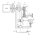
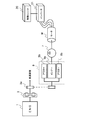
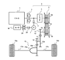
- FIG. 1 shows an oil supply apparatus according to a first embodiment of the present invention, and is a schematic view when applied to an automatic transmission mounted on a vehicle. It is a figure which extracts and shows in detail the principal part of the oil supply apparatus shown in FIG. It is a figure which shows the structural example of the fastening release element in the oil supply apparatus shown in FIG.1 and FIG.2. It is a figure which shows the other structural example of the fastening release element in the oil supply apparatus shown in FIG.1 and FIG.2. It is a figure for demonstrating the operation
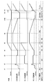
- working scene. 6 is a time chart showing a relationship between a vehicle speed, an engine speed, a motor speed and a pump speed in the operation pattern shown in FIG.
- FIG. 8 is a time chart showing the relationship between the vehicle speed, the engine speed, the motor speed and the pump speed in the operation pattern shown in FIG. It is a figure which extracts and shows in detail the principal part of the oil supply apparatus which concerns on the 2nd Embodiment of this invention. The oil supply apparatus which concerns on the 3rd Embodiment of this invention is shown, and it is the schematic at the time of applying to the automatic transmission mounted in a vehicle.
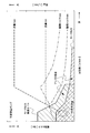
- FIG. 11 is a characteristic diagram showing a relationship between engine speed and drive torque when performing an assist operation in the system configuration of FIG. 10.
- FIG. 11 is a characteristic diagram illustrating a relationship between an engine speed and a driving torque when an assist operation is performed using a variable displacement pump in the system configuration of FIG. 10.
- the oil supply apparatus which concerns on the 4th Embodiment of this invention is shown, and it is the schematic at the time of applying to the automatic transmission mounted in a vehicle. It is a figure which shows the structural example of the 1st, 2nd one-way clutch in the system shown in FIG.
- the oil supply apparatus which concerns on the 5th Embodiment of this invention is shown, and it is the schematic at the time of applying to the automatic transmission mounted in a vehicle.
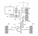
- FIG. 1 shows an oil supply apparatus according to a first embodiment of the present invention.
- FIG. 1 is a schematic diagram when a prime mover of a vehicle is an engine (internal combustion engine) and is applied to an automatic transmission of the engine.
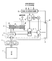
- FIG. 2 shows the details of the essential parts of the oil supply apparatus shown in FIG.
- An engine (ENG) 1 that is a power source of the vehicle has an idle stop function, and automatically stops the engine 1 by stopping fuel supply to the engine 1 under a predetermined idle stop condition. Thereafter, the supply of fuel to the engine 1 is resumed when the idle stop cancellation condition is satisfied, and the engine 1 is started.
- An output shaft of the engine 1 is connected to a transmission (automatic transmission) 3 via a torque converter 2.
- the transmission 3 includes a clutch 4, a continuously variable transmission 5, an oil pump 7, a one-way clutch 9 (first engagement / release means) that functions as an engagement / release element, and the like.
- the clutch 4 is constituted by a wet multi-plate clutch, and the fastening / release is controlled by hydraulic control of hydraulic oil.
- the clutch 4 is a friction engagement element in the forward / reverse switching mechanism.
- the forward / reverse switching mechanism includes, for example, a planetary gear mechanism including a ring gear, a pinion and a pinion carrier connected to the engine output shaft, a sun gear connected to the transmission input shaft, a reverse brake for fixing the transmission case to the pinion carrier,
- a forward clutch that connects the machine input shaft and the pinion carrier is configured to switch between forward and reverse of the vehicle.
- the forward clutch and the reverse brake which are friction engagement elements in the forward / reverse switching mechanism, correspond to the clutch 4.
- the continuously variable transmission 5 includes a primary pulley 5a and a secondary pulley 5b, and a belt 5c wound around the pulleys 5a and 5b.
- the rotation of the primary pulley 5a is transmitted to the secondary pulley 5b via the belt 5c.
- the rotation of the secondary pulley 5b is transmitted from the output shaft 10 to the drive wheels 16a and 16b.
- the movable conical plate of the primary pulley 5a and the movable conical plate of the secondary pulley 5b are moved in the axial direction by hydraulic control of the respective hydraulic oil, and the pulleys 5a, 5b and the belt 5c are moved.
- the gear ratio can be changed steplessly by changing the pulley ratio (rotation ratio) of the primary pulley 5a and the secondary pulley 5b.
- the oil pump 7 has a drive shaft coupled to the output shaft of the engine 1 via a one-way clutch 9 and is coupled to the rotating shaft of the motor M, and is selected by one or both of the engine 1 and the motor M as a power source. Driven.
- a final gear 11 is fixed on the output shaft 10 of the continuously variable transmission 5.
- a counter shaft 13 is arranged in parallel to the output shaft 10.
- the output shaft 10 and the counter shaft 13 are coupled via a counter gear pair 12.
- the counter gear pair 12 is configured by meshing a final gear 11 and a gear 12 a fixed to the counter shaft 13.
- the countershaft 13 is connected to the drive wheels 16a and 16b via a differential gear unit 15 between the drive wheels 16a and 16b.
- the differential gear unit 15 includes a gear case 15a containing a side gear (not shown) connected to drive wheels 16a and 16b via axles 17a and 17b, and a gear 15b fixed to the outer periphery of the gear case 15a. I have.
- a gear 14 fixed on the counter shaft 13 is engaged with the gear 15 b of the differential gear unit 15.
- the counter shaft 13 is coupled to the drive wheels 16a and 16b via the differential gear unit 15 so as to rotate in conjunction with the drive wheels 16a and 16b.
- oil is stored in the oil pan 6 at the bottom of the case of the transmission 3, and this oil is sucked and pressurized by the oil pump 7, and the clutch 4 and the pulley are connected via the pressure adjusting mechanism 8. It is supplied as hydraulic oil to the hydraulic actuators 5a and 5b.
- the oil pump 7 is provided in the case of the transmission 3 and is driven by the engine 1 by a sprocket 3 a provided on the input shaft of the transmission 3, and the drive shaft is coupled to the rotation shaft of the motor M.
- the motor M can also be driven.
- a one-way clutch 9 is provided between the input shaft of the transmission 3 and the drive shaft of the oil pump 7. The one-way clutch 9 fastens the engine 1 and the oil pump 7 when the rotational speed of the drive section by the engine 1 is higher than the rotational speed of the motor M, and the rotational speed of the drive section by the engine 1 is greater than the rotational speed of the motor M. Also release when it is low.
- the one-way clutch 9 is engaged during normal rotation of the engine 1, and the oil pump 7 is driven by the driving force of the engine 1.
- the one-way clutch 9 is released, and the oil pump 7 is driven by the driving force of the motor M.
- the driving force of the engine 1 can be assisted by applying a driving force from the motor M as necessary. In this way, the oil pump 7 is selectively driven by one or both of the engine 1 and the motor M, which are power sources, as indicated by the dashed arrows.
- the motor M has a capacity (driving force) that is normally used for idle stop. For this reason, basically, even if the motor M rotates at the maximum rotation speed or maximum output, it is smaller than the output of the engine 1 and does not overtake the rotation of the oil pump driven by the engine.
- the pressure regulating mechanism 8 includes an electromagnetic valve having a relief function for each supply part (clutch 4 and pulleys 5a and 5b). Under the control of a control unit (C / U) 20 including a microcomputer, the pressure adjusting mechanism 8 adjusts the discharge pressure of the oil pump 7 to the target pressure of each supply part and supplies it to each supply part. Thereby, the forward / reverse switching of the vehicle and the control of the gear ratio are performed.
- the inverter (INV) 21 is controlled based on the control of the control unit 20 by PWM control (control for generating a voltage whose pulse width is modulated at a constant period in order to obtain a pseudo sine wave). ) Is converted into an AC voltage and supplied to the motor M.
- the oil pump 7 supplies oil as operating oil to the clutch 4 and the pulleys 5a and 5b via the pressure adjusting mechanism 8, and supplies lubricating and cooling oil to each part of the transmission 3.
- the supplied oil is returned to the oil pan 6 and circulated.
- An oil temperature sensor 30 is provided in the oil pan 6.
- FIG. 3 shows a configuration example of the one-way clutch 9 in the oil supply apparatus shown in FIGS. 1 and 2. 3, parts corresponding to those in FIGS. 1 and 2 are denoted by the same reference numerals. Since the smaller inertia is advantageous in terms of responsiveness when the motor M changes from the stopped state to the driven state, in this example, the inner shaft of the one-way clutch 9 has a small inertia on the output shaft (pump shaft) side of the motor M. The outer 9b is connected to the output shaft side (drive system) of the engine 1 by the sprocket 3a.
- the output shaft (drive system) of the engine 1 is disconnected from the drive shaft of the oil pump 7 by the one-way clutch 9, the load during driving by the motor M can be minimized. Further, by using the one-way clutch 9, it is possible to perform engagement / release with the output shaft of the engine 1 without hydraulic pressure.
- the relationship between the inner 9a and the outer 9b, 9b of the one-way clutch 9 can be reversed. For example, when there is a margin in the driving force of the motor M and priority is given to reducing engine load over responsiveness.
- the output shaft side of the motor M may be connected to the outer 9b, 9b of the one-way clutch 9, and the inner 9a may be connected to the output shaft side of the engine 1 by the sprocket 3a.
- FIG. 4 is a diagram showing another configuration example of the fastening release element in the oil supply apparatus shown in FIGS. 1 and 2.
- a mechanical clutch 22 such as a friction clutch, a meshing clutch, a single plate clutch, a centrifugal clutch, and an electromagnetic clutch, is used instead of the one-way clutch 9, a mechanical clutch 22, such as a friction clutch, a meshing clutch, a single plate clutch, a centrifugal clutch, and an electromagnetic clutch.
- the mechanical clutch 22 is in an engaged state (clutch ON) when driven by the engine 1 and in a released state (clutch OFF) when driven by the motor M.
- the mechanical clutch 22 cannot be released due to an abnormality of the clutch actuator, it cannot run. Further, in the released state, it is necessary to continue to apply hydraulic pressure during traveling, which leads to energy loss. Therefore, a configuration in which the engaged state is normally set (normal CLOSE) is preferable.
- the clutch OFF is preferably performed when a predetermined number of rotations (required flow rate) is reached after the motor is driven. This is because if the clutch is turned off in a state where the number of rotations of the motor M is insufficient, the flow rate of oil may be insufficient.
- the case where one oil pump 7 is switched and driven by the engine 1 and the motor M has been described.
- the oil pump 7 is driven by both the engine 1 and the motor M, and the oil pump 7 is driven by the engine 1.
- the force can be assisted by the motor M.
- the target rotational speed of the motor M is set to be equal to or higher than the rotational speed of the engine 1 so as to be able to assist through the one-way clutch 9.
- the engagement / release does not depend on the rotation speed of the engine 1, and the torque amount of the motor M becomes the assist amount as it is, so that the rotation speed of the motor M is easy according to the assist target.
- the difficulty of motor control (oil pump assist) can be reduced.
- the motor capacity is relatively small so that it is used for normal idle stop.
- the motor capacity is large, the required oil supply amount does not depend on the engine driving force (running state). Accordingly, the motor M can be optimally controlled. That is, at the time of idling stop, the one-way clutch 9 is released, so that the necessary amount of oil can be supplied by the motor M. Moreover, if there is a margin in the motor capacity, the optimum flow rate can be achieved within that range.
- the driving force exceeding the oil pressure holding area can be used for assist. Thus, if the motor capacity is increased, the degree of freedom of use can be increased.
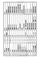
- FIG. 5 is a diagram for explaining an operation pattern for each traveling scene.
- FIG. 6 is a time chart showing the relationship between the vehicle speed, the engine speed, the motor speed, and the pump speed in the operation pattern shown in FIG.
- the motor M is driven according to the driving situation of the vehicle.
- the motor M is rotated at a speed equal to or higher than the rotation speed of the oil pump 7. If the assist amount is too large, the pump rotational speed is too high and waste occurs. Therefore, the rotational speed of the motor M is set so that an appropriate assist amount is obtained.
- the minimum value of the assist amount can be determined from, for example, the driving torque of the engine 1 during creep (changed with oil temperature) that is considered to have the smallest load. It is desirable to determine whether or not to assist in consideration of at least the remaining battery level when there is a margin in power. In this determination, it is more preferable to consider whether, for example, the temperature of the battery is not too low or whether a failure flag is set so that the motor M does not operate.
- the shift range is parking P
- the one-way clutch (OWC) 9 is ON (engaged)
- the motor M is in a stopped state, which is the same as before.
- the starter is operated at time t1
- the engine 1 is started and the engine speed increases, and the pump speed also increases accordingly.
- the motor M is in a stopped state.
- the assist by the motor M is stopped except when the engine 1 is at a low speed, and the oil pump 7 is driven only by the driving force of the engine 1. That is, at an engine speed with good engine efficiency, for example, 4000 r / min or more, the oil pump 7 is driven with priority given to the driving force of the engine 1.
- the assisting effect with the low speed rotation with the poor efficiency of the engine 1 has the effect of improving the fuel efficiency. high.
- fuel efficiency can be improved by assisting during rapid acceleration with a heavy load on the engine 1.
- the oil pump 7 maintains a predetermined pump speed by driving the motor M. In this way, the oil pump 7 is driven by the motor M just before the engine stops at the idle stop to prepare for the idle stop.
- the idle stop preparation start timing is determined from time (for example, how many msec rises depending on temperature) and a measured value of hydraulic pressure in consideration of hydraulic response by motor drive.
- the engine 1 In the coast stop, the engine 1 is stopped when the vehicle speed becomes a predetermined low speed, for example, 10 km / h or less. Therefore, the oil pump 7 is driven by the motor M just before the engine stops at the coast stop to prepare for the coast stop.
- a predetermined low speed for example, 10 km / h or less. Therefore, the oil pump 7 is driven by the motor M just before the engine stops at the coast stop to prepare for the coast stop.
- the engine 1 stops due to idle stop (time t8).
- the one-way clutch 9 is in a disengaged state, and the oil pressure is maintained by driving the oil pump 7 by the motor M, and the oil pump 7 maintains a predetermined pump speed.
- the motor M does not assist during idle stop after deceleration and vehicle stop.
- the hydraulic pressure is maintained during idling stop, it is sufficient that the oil leaking from the pulleys 5a and 5b and the clutch 4 can be supplied so that the load on the motor M is relatively small.
- the motor M is controlled by current so that the oil supplied from the oil pump 7 has a necessary flow rate, or is controlled by the motor M so that the oil pump 7 has a predetermined rotational speed. .
- the engine starts at time t9, the shift range changes from neutral N to reverse R or drive D, and when the vehicle starts at time t10, the one-way clutch 9 changes from OFF (released) to ON (engaged), and the motor M Switches from the hydraulic holding operation to the assist operation.
- This control switching condition is when “engine drive speed> motor speed” is satisfied.
- the same operation is repeated according to the driving state of the vehicle, such as acceleration, steady running state, deceleration, lower than a predetermined speed or stop.
- the motor M can secure the hydraulic pressure at the idle stop (coast stop) while simplifying the system configuration. Moreover, by driving the oil pump 7 with both the engine 1 and the motor M, a new function of assisting the driving force of the engine 1 with the motor M and reducing the engine power load can be added. Reduction of engine power load contributes to improvement of fuel consumption.
- the structure can be simplified while securing the existing functions, and the power load can be reduced by assisting a part of the load of the prime mover (engine).
- the prime mover engine
- FIG. 7 is a diagram for explaining another operation pattern for each traveling scene.
- the motor M is driven in accordance with the driving state of the vehicle.
- FIG. 8 is a time chart showing the relationship between the vehicle speed, the engine speed, the motor speed and the pump speed in the operation pattern shown in FIG. 7, and the motor operation and the running scene. Also in the second embodiment, the motor M is driven in accordance with the driving situation of the vehicle as in the first embodiment.
- the driving scene No. As shown in (1), when the one-way clutch 9 is engaged before the engine 1 is started, the operation is the same as that in FIG. On the other hand, the traveling scene no. As shown in (1 '), by releasing the one-way clutch 9 before the engine 1 is started, the oil pump 7 is driven only by the motor M during a period until the engine 1 starts (between times t1 and t2). . By setting the motor rotation speed higher than the engine rotation speed as indicated by the arrow between times t1 and t2 in FIG. 8, the pump rotation speed also increases in proportion to the motor rotation speed, and the one-way clutch 9 is in the released state. Thus, the load on the engine 1 can be reduced and the engine start can be assisted.
- the motor M when the battery power is sufficient, when the starter is turned, the motor M is driven in the forward rotation direction from the start of the starter until the first explosion of the engine 1 after receiving the engine start signal.
- the motor M assists the starting.
- the capacity (output) of the starter Since the capacity (output) of the starter has been determined, the load due to the oil pump 7 can be reliably reduced, and the starter can be rotated faster as much as the start load is reduced, so that the start response can be improved. As a result, the hydraulic pressure supply response can be improved and the starter driving load can be reduced by early driving of the oil pump 7.
- the motor M can be stopped not by idling stop, but when other idling stop permission conditions are not satisfied, such as brake-off and driver seat belt.
- the motor speed is set to a different value when the engine is started and when the engine is started (idle stop release). Since the engine speed is higher because the engine is warming up at the time of starting, the set value is “start time ⁇ It is good to say "When starting up”
- the number of motor revolutions when starting the engine reaches the engine based on one of water temperature, oil temperature (engine, transmission / reduction gear), ambient temperature, and the number of revolutions (engine, motor) at the previous start. The number of revolutions can be predicted and set. Moreover, you may correct
- FIG. 9 shows an extracted main part of an oil supply apparatus according to the second embodiment of the present invention.
- a flow rate / hydraulic pressure increase prediction device (flow rate / hydraulic pressure increase prediction means) 23 is provided.
- the flow rate / hydraulic pressure increase prediction device 23 predicts an increase in oil flow rate and hydraulic pressure based on various control signals and sensor measurement values.
- Various control signals include, for example, a shift request, a lubrication cooling request, a downshift request in a manual mode, and a brake switch state.
- the measured values of various sensors include the amount of change in throttle opening (accelerator opening, intake air amount), brake pedal force, brake fluid pressure, brake stroke amount / brake speed, and the like. Either of these control signals or sensor measurement values is selectively used. Based on the increase prediction of the flow rate / hydraulic pressure, control is performed so that the driving state of the motor M is optimized.
- the control program of the control unit 20 is changed so that an increase in the oil flow rate and hydraulic pressure is predicted based on various control signals and signals from existing sensors, so that the control unit 20 is controlled in flow rate / hydraulic pressure. It can also be used as the increase prediction device 23. Since the other basic configuration is the same as that of the first embodiment, the same components in FIG. 9 as those in FIG. 2 are denoted by the same reference numerals, and detailed description thereof is omitted.
- the motor M is stopped when the relationship of “engine rotation speed> motor rotation speed” and “motor rotation speed> predetermined value 1” is satisfied, and the assist is restarted when “motor rotation speed ⁇ predetermined value 2” is satisfied.
- the end of assist is the timing when the one-way clutch 9 is turned off.
- the predetermined value 2 when the assist is resumed is the timing when the one-way clutch 9 is turned on.
- the oil flow rate is increased to improve lubrication and cooling.
- a predetermined value high temperature
- “engine speed ⁇ motor speed” The motor M is driven so as to increase the rotational speed so that the lubrication / cooling flow rate increases.
- the lubrication / cooling flow rate can be secured by increasing the oil flow rate while avoiding an increase in the engine speed, which is effective during high-speed running and traffic jams.
- the motor M is driven so that “engine speed ⁇ motor speed”. By doing in this way, warming-up (oil temperature rise) acceleration by the heat generation of the motor M can be expected.
- the motor operation is changed based on the oil temperature state. For example, at low oil temperatures, the oil becomes highly viscous and the pump drive load increases, so the motor assist amount increases as the temperature decreases. At this time, the rotational speed that is the required flow rate of oil is the upper limit of the motor target rotational speed.
- the motor M has a surplus power, the pump rotation speed exceeding the upper limit of the motor target rotation speed is wasted, so that the target rotation speed is not exceeded.
- the motor M has no surplus power, the motor M is driven with full power, so the current amount and driving time are set within a range where heat resistance can be guaranteed.
- the difference between the actual oil temperature and the detected oil temperature is determined based on the oil temperature increase rate per unit time, the engine speed, the vehicle speed, the high oil pressure, and the like that are the main factors that increase the oil temperature. Can be expected to occur.
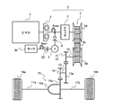
- FIG. 10 shows an oil supply apparatus according to a third embodiment of the present invention, and is a schematic diagram when applied to an automatic transmission mounted on a vehicle.
- a gear (gear) 24 is provided between the oil pump 7 and the motor M. Since other basic configurations are the same as those of the first and second embodiments, the same components in FIG. 10 as those in FIG. 1 are denoted by the same reference numerals, and detailed description thereof is omitted.
- FIG. 11 is a characteristic diagram showing the relationship between the engine speed and drive torque when performing the assist operation in the system configuration of FIG.
- the oil pump 7 is applied with a driving torque that increases as the engine speed increases.
- FIG. 12 is a characteristic diagram showing the relationship between the engine speed and the drive torque when the assist operation is performed using the variable displacement pump in the system configuration of FIG.
- n of the gear 24 2
- the drive torque of the oil pump (variable displacement pump) 7 has a peak that differs between when the drive torque is minimum (drive torque min) and when the drive torque is maximum (drive torque max). After increasing at a similar increase rate until reaching the number of revolutions, gradually decreases.
- the oil flow rate (flow rate min, flow rate max) increases at a similar increase rate until reaching a predetermined rotational speed, and then becomes constant.
- the drive torque min, drive torque max, flow rate min, and flow rate max are determined by the specifications of the variable displacement pump.
- the variable displacement pump has a variable region where the flow rate changes according to the number of rotations and a region where the oil flow rate becomes constant after reaching a predetermined number of rotations.
- the flow rate can be made constant, and the driving torque can be lowered in the high-speed rotation region. Therefore, even if a variable displacement pump is used, a sufficient assist effect can be obtained by specializing in a specific region.
- variable displacement pump When a variable displacement pump is used, it is preferable to add a motor capacity (size) and a reduction gear (gear 24) so that motor assistance can be performed using a region other than the variable region.
- a motor capacity size
- a reduction gear gear 24
- the I / S required flow rate can be satisfied as shown by being surrounded by a broken line.
- n By reducing the rotation of the motor M with the gear 24 at a predetermined reduction ratio 1: n, it is possible to positively assist a low rotation region with low engine efficiency with a large driving force according to the reduction ratio.
- FIG. 13 shows an oil supply apparatus according to a fourth embodiment of the present invention, and is a schematic diagram when applied to an automatic transmission mounted on a vehicle.
- a second one-way clutch 25 (second engagement / release means) that is an element that can be transmitted and disconnected, that is, an engagement / release element, is provided between the oil pump 7 and the motor M. Since the other basic configuration is the same as that of the first to third embodiments, the same reference numerals in FIG. 13 denote the same components as those in FIGS. 1 and 10, and a detailed description thereof will be omitted.
- the second one-way clutch 25 it is possible to release the rotation of the motor M when the oil pump 7 is driven only by the engine 1.
- the motor M specialized for the engine low-speed region is employed, the effect of reducing the load is great, and an increase in cost due to high-speed support of the bearings and seals can be avoided.
- the maximum value of the rotational speed of the motor M is 4000 r / min, if the motor M is decelerated, the motor M rotates at a higher speed than that, but the motor M can be disconnected by the one-way clutch 25 during the high-speed rotation.
- the degree of freedom in controlling and using the motor M can be increased.
- the motor M and the oil pump 7 are directly connected, there is a possibility that the vehicle cannot be started when the motor fails.
- the second one-way clutch 25 the motor M can be disconnected and the reliability is improved. From the viewpoint of this, it is preferable.
- FIG. 14 is a diagram showing a configuration example of the fastening release element in the system shown in FIG.
- the drive shaft (pump shaft) of the oil pump 7 is connected to the inner 9a, 25a where the inertia of the one-way clutch 9, 25 is small, and the outer 9b, 9b of the one-way clutch 9 is connected to the output shaft of the engine 1 by the sprocket 3a. is doing.
- the outers 25b and 25b of the one-way clutch 25 are connected to the output shaft (pump shaft) of the motor M.
- the power of the oil pump 7 can be switched at the time of idling stop by the difference between the rotation speeds of the engine 1 and the motor M.
- a mechanical clutch such as a friction clutch, a meshing clutch, a single plate clutch, a centrifugal clutch and an electromagnetic clutch can be used instead of the one-way clutch 9 and / or 25.
- FIG. 15 shows an oil supply apparatus according to a fifth embodiment of the present invention, and is a schematic diagram when applied to an automatic transmission mounted on a vehicle.
- a one-way clutch 25 that is an element that can be transmitted or cut off between the oil pump 7 and the motor M, that is, a fastening release element, is provided, and a gear 24 is further provided between the one-way clutch 25 and the motor M.
- the present invention in the first to fifth embodiments, the case where the present invention is applied to an oil pump of an automatic transmission has been described as an example. However, the present invention can be similarly applied to other oil supply devices such as lubricating oil. Of course.
- the flow rate / hydraulic pressure increase prediction device 23 may be provided in the same manner as in the second embodiment, and the control, configuration, and method as described in Use Example 1 to Use Example 9 are provided. These may be combined as appropriate.
Landscapes
- Engineering & Computer Science (AREA)
- General Engineering & Computer Science (AREA)
- Mechanical Engineering (AREA)
- Control Of Transmission Device (AREA)
- Hybrid Electric Vehicles (AREA)
- General Details Of Gearings (AREA)
Abstract
Description
変速機がニュートラル状態になると、エンジンの起動により油圧が上昇したときに係合し、回転数差があるため振動が発生する。また、クラッチへの潤滑・冷却用のオイルの供給が停止されると、クラッチの冷却が不十分となり、その発熱が問題となることもある。
更に、特許文献2では、エンジンと走行用モータで駆動される機械式オイルポンプに加えて、専用のモータで駆動される電動オイルポンプを設け、機械式オイルポンプの回転数が低い領域において吐出量の不足を補っている。
更に、特許文献3に記載されている技術では、HEVにおける走行用モータを駆動源として油圧ポンプを駆動するため、状況によりエンジン負荷の一部をモータが補うなどして、任意に補助的な駆動を行うのは困難であった。
[第1の実施形態]
図1は、本発明の第1の実施形態に係るオイル供給装置を示すもので、車両の原動機がエンジン(内燃機関)で、このエンジンの自動変速機に適用する際の概略図である。また、図2は図1に示したオイル供給装置の要部を抽出して詳細に示している。
エンジン1の出力軸は、トルクコンバータ2を介して、変速装置(自動変速機)3に接続されている。変速装置3は、クラッチ4、無段変速機5、オイルポンプ7及び締結解放要素として働くワンウェイクラッチ9(第1の締結解放手段)などを含んで構成されている。
モータMが停止状態から駆動状態になるときに、イナーシャが小さい方が応答性の点で有利であるので、本例ではモータMの出力軸(ポンプ軸)側をワンウェイクラッチ9のイナーシャが小さいインナー9aと接続し、アウター9b,9bをスプロケット3aによりエンジン1の出力軸側(駆動系)に接続している。
図5は走行シーン別の動作パターンについて説明するための図である。また、図6は図5に示した動作パターンにおける車速、エンジン回転数、モータ回転数及びポンプ回転数と、モータ動作及び走行シーンとの関係を示すタイムチャートである。本実施例1では、モータMを車両の運転状況に応じて駆動している。
なお、モータMによるオイルポンプ7の駆動からエンジン1によるオイルポンプ7の駆動に切り替える時には、モータMの駆動をタイミング良く停止しないとエンジン1による駆動の負荷になる。逆に、エンジン1によるオイルポンプ7の駆動からモータMによるオイルポンプ7の駆動に切り替える時には、モータMをタイミング良く回転させ始めないとエンジン1が負荷になる。よって、切り替え動作のタイミングの設定に配慮する必要がある。
図7は走行シーン別の他の動作パターンについて説明するための図であり、モータMを車両の運転状況に応じて駆動している。また、図8は図7に示した動作パターンにおける車速、エンジン回転数、モータ回転数及びポンプ回転数と、モータ動作及び走行シーンとの関係を示すタイムチャートである。本実施例2でも、上述した実施例1と同様にモータMを車両の運転状況に応じて駆動している。
また、エンジン始動時のモータ回転数は、水温、油温(エンジン、変速機・減速機)、周囲温度、前回始動時の回転数(エンジン、モータ)履歴、のいずれかに基づいてエンジンの到達回転数を予測し、設定することができる。また、前回始動時の履歴を用いてモータ回転数を補正しても良い。
図9は、本発明の第2の実施形態に係るオイル供給装置の要部を抽出して示している。本実施形態では、図2に示したシステム構成に加えて、流量・油圧増加予測装置(流量・油圧増加予測手段)23を設けている。流量・油圧増加予測装置23は、各種の制御信号やセンサの計測値に基づいてオイルの流量や油圧の増加を予測する。各種の制御信号には、例えば変速要求、潤滑冷却要求、マニュアルモードでのシフトダウン要求、及びブレーキスイッチの状態等が含まれる。各種のセンサの計測値には、スロットル開度(アクセル開度、吸入空気量)の変化量、ブレーキ踏力、ブレーキ液圧、ブレーキストローク量/ブレーキ速度等が含まれる。これらの制御信号やセンサの計測値のいずれかを選択的に用いる。そして、この流量・油圧の増加予測に基づいてモータMの駆動状態が最適となるように制御する。
なお、制御ユニット20の制御プログラムを変更し、各種の制御信号や既存のセンサ類からの信号に基づいてオイルの流量や油圧の増加を予測するようにすることで、制御ユニット20を流量・油圧増加予測装置23として利用することもできる。
他の基本的な構成は第1の実施形態と同様であるので、図9において図2と同一構成部分には同じ符号を付して、その詳細な説明は省略する。
(使用例1)
本使用例1は、エンジン1のアシストにモータMを利用し、モータMをオイルの目標流量に応じて駆動するもので、流量・油圧増加予測装置23で目標値が増加することを予測検知した時、モータ回転数を上昇させるものである。
これによって、オイルの必要流量の応答性向上と、モータアシストの継続によるエンジン負荷の低減が図れる。
本使用例2は、オイルの流量を増加させて潤滑・冷却を向上させるもので、油温センサ30で検知した油温が所定値以上(高温)の時に、「エンジン回転数<モータ回転数」となるようにモータMの回転数を上げて駆動し、潤滑・冷却流量が増加するよう制御する。このような制御によって、エンジン回転数の上昇を回避しつつ、オイル流量を増加させることで潤滑・冷却流量を確保でき、高速走行や渋滞時に有効である。
これに対し、油温が所定値以下(低温)の時には、「エンジン回転数<モータ回転数」となるようモータMを駆動する。このようにすることで、モータMの発熱による暖機(油温上昇)促進が期待できる。
極低温環境などで、例えばオイルがゲル状になってしまい、モータ能力上、駆動できない領域は、モータアシストを許可しないように設定する。例えば油温センサ30で検知した油温(モータ温度などでも良い)が所定値1より低い場合にはモータ駆動を許可しない。そして、油温が所定値2以上となったときにモータ駆動を許可する。他の条件として、低電圧で電圧が足りない、他部品が故障(例えばリレー)で本制御が実施できない、または制御可能な操作量が不十分な場合にも、モータアシストを許可しないように設定する。
本使用例4は、シリンダー位置の調整を行うものである。エンジン停止後にモータMを逆回転させることでエンジン1のクランク軸を回動させ、特定のシリンダーを予め設定した位置に移動させる。ワンウェイクラッチ9は、逆回転させるとロックされるので、エンジン停止後にモータMを逆回転させるとエンジン出力軸も回すことができる。これを利用して、エンジン停止時に、クランク軸を回動させ、ある特定のシリンダーを始動性が良くなる位置に調整し、エンジン1の始動性を高めることができる。
アイドルストップ時には、高油温ほどオイルポンプ7の漏れ流量が増加するため、油温センサ30で検出した油温が高くなるほどモータMの目標回転数を増大させるように制御する。この油圧保持動作には、例えばモータMへの電流制御を行う。一方、低油温時はオイルポンプ7の漏れ流量が低下するが、極低温時はオイルが高粘度となり圧力損失が増加するため、各油温におけるオイルポンプ7の容積効率を考慮し、モータMの目標回転数を設定する。また、油温に限らず、水温他、運転状況での各部の変化内容に応じて、モータMの目標回転数を設定すると良い。
冷却水を用いてトランスミッションオイル温度を上昇させる機構を設けることで、暖機の早期化を図ることができる。
(使用例7)
急激な油温上昇が発生する場合、油温センサ30による検出値でモータMを制御していると、実油温と検出油温との相違が発生し、オイル供給量が不足することがある。そこで、上記流量・油圧増加予測装置23で油温の相違が発生することを予測するようにし、油温の相違が予測された場合にはオイル供給量の目標値を増加させる。流量・油圧増加予測装置23では、単位時間当たりの油温上昇率や、油温を上昇させる主な要因であるエンジン回転数、車速、高油圧などから実油温と検出油温との相違が発生するのを予測できる。
ワンウェイクラッチ9のOFF故障時(解放故障時)には、エンジン駆動力でオイルポンプ7を駆動できないため、モータMのみで駆動する。この時、モータ出力に応じた油圧となるため、エンジン駆動力制限や変速比固定等を行うことでトランスミッションに入力される駆動力を低減させて走行制限を行う。
(使用例9)
エンジン始動後、モータアシストしていない状態で、規定の油圧に達していることを確認することで、ワンウェイクラッチ9のOFF故障診断を実施できる。例えば、アイドル回転時に、油圧センサ出力値が0.3MPa未満で目標油圧が最大値になる場合にはOFF故障と判定する。
図10は、本発明の第3の実施形態に係るオイル供給装置を示すもので、車両に搭載される自動変速機に適用する際の概略図である。本実施形態では、オイルポンプ7とモータM間に歯車(ギヤ)24を設けている。
他の基本的な構成は第1、第2の実施形態と同様であるので、図10において図1と同一構成部分には同じ符号を付して、その詳細な説明は省略する。
これに対し、歯車24により減速比1:2で減速すると、モータ出力はモータ回転の上昇に伴って低下するものの、減速しない場合のエンジン回転数の1/2まで、ほぼ2倍の大きな駆動トルクがアシスト用に得られる。
このように、どちらの場合も破線で囲んで示すアイドルストップ時の要求オイル流量(I/S要求流量)を満たすことができるが、歯車24でモータMの回転を減速することにより、エンジン効率の悪い低回転領域を大きな駆動力で積極的にアシストすることができる。
可変容量ポンプは、回転数に応じて流量が変化する可変領域と、所定の回転数に到達した後はオイルの流量が一定になる領域とがあり、回転数が上昇しても吐出するオイルの流量を一定にでき、高速回転領域では駆動トルクを下げることができる。
従って、可変容量ポンプを用いても特定の領域に特化することで十分なアシスト効果が得られる。
このように、オイルポンプ7に可変容量ポンプを用いても、破線で囲んで示すようにI/S要求流量を満たすことができる。また、歯車24でモータMの回転を所定の減速比1:nで減速することにより、エンジン効率の悪い低回転領域を減速比に応じた大きな駆動力で積極的にアシストすることができる。
図13は、本発明の第4の実施形態に係るオイル供給装置を示すもので、車両に搭載される自動変速機に適用する際の概略図である。本実施形態は、オイルポンプ7とモータM間に伝達及び遮断可能な要素、すなわち締結解放要素である第2のワンウェイクラッチ25(第2の締結解放手段)を設けたものである。
他の基本的な構成は第1乃至図3の実施形態と同様であるので、図13において図1並びに図10と同一構成部分には同じ符号を付して、その詳細な説明は省略する。
なお、モータ回転数を制御する時には、ポンプ回転数を認識する必要がある。このポンプ回転数は、例えばエンジン回転数やモータ位置センサ等を用いて推定できる。
なお、図4と同様に、ワンウェイクラッチ9及び/または25に代えて機械式クラッチ、例えば摩擦クラッチ、噛み合いクラッチ、単板クラッチ、遠心クラッチ及び電磁クラッチなどを用いることもできるのは勿論である。
図15は、本発明の第5の実施形態に係るオイル供給装置を示すもので、車両に搭載される自動変速機に適用する際の概略図である。本実施形態では、オイルポンプ7とモータM間に伝達又は遮断可能な要素、すなわち締結解放要素であるワンウェイクラッチ25を設けるとともに、更にワンウェイクラッチ25とモータM間に歯車(ギヤ)24を設けている。
このような構成では、第4の実施形態による効果に加えて第3の実施形態による効果もえられる。
また、第3乃至第5の実施形態において、第2の実施形態と同様に流量・油圧増加予測装置23を設けても良く、使用例1から使用例9で説明したような制御や構成、方法などを適宜組み合わせることもできる。
Claims (17)
- 車両の原動機と前記原動機とは別のモータとにより駆動されるオイルポンプと、前記原動機の駆動力を前記オイルポンプに伝達する第1の締結解放手段とを備え、前記原動機の駆動系を介することなく前記モータにより前記オイルポンプを駆動する、オイル供給装置。
- 前記第1の締結解放手段が、第1のワンウェイクラッチである、請求項1記載のオイル供給装置。
- 前記第1のワンウェイクラッチは、前記原動機による駆動部の回転数が前記モータの回転数よりも高いときに前記原動機と前記オイルポンプを締結し、前記原動機による駆動部の回転数が前記モータの回転数よりも低いときに解放する、請求項2記載のオイル供給装置。
- 前記第1の締結解放手段が、前記原動機で前記オイルポンプを駆動するときには締結状態、前記モータで前記オイルポンプを駆動するときには解放状態とされる機械式クラッチである、請求項1記載のオイル供給装置。
- 前記機械式クラッチが、摩擦クラッチ、噛み合いクラッチ、単板クラッチ、遠心クラッチ及び電磁クラッチのいずれかを含む、請求項4記載のオイル供給装置。
- 前記原動機により前記オイルポンプを駆動中に、前記モータを動作させる、請求項1記載のオイル供給装置。
- 前記モータは、車両の運転状況に応じて前記オイルポンプを駆動する、請求項1記載のオイル供給装置。
- 前記モータは、前記原動機の駆動負荷状態に応じて前記オイルポンプを駆動する、請求項1記載のオイル供給装置。
- 制御信号及びセンサの計測値に基づいてオイルの流量と油圧の増加を予測する流量・油圧増加予測手段を更に備え、前記流量・油圧の増加予測に基づいて前記モータの駆動状態を制御する、請求項1記載のオイル供給装置。
- 前記制御信号は、変速要求、潤滑冷却要求、マニュアルモードでのシフトダウン要求、及びブレーキスイッチの状態の少なくともいずれか1つを含み、前記センサの計測値は、スロットル開度の変化量、ブレーキ踏力、ブレーキ液圧、及びブレーキストローク量/ブレーキ速度の少なくともいずれか1つを含む、請求項9記載のオイル供給装置。
- 前記モータの回転を減速して前記オイルポンプを駆動するギヤを更に備える、請求項1記載のオイル供給装置。
- 前記モータの駆動力を前記オイルポンプに伝達する第2の締結解放手段を更に備える、請求項1に記載のオイル供給装置。
- 前記第2の締結解放手段が、第2のワンウェイクラッチである、請求項12記載のオイル供給装置。
- 前記第2のワンウェイクラッチは、前記原動機による駆動部の回転数が前記モータの回転数よりも低いときに前記モータと前記オイルポンプを締結し、前記原動機による駆動部の回転数が前記モータの回転数よりも高いときに解放する、請求項13記載のオイル供給装置。
- 前記第2の締結解放手段が、前記原動機で前記オイルポンプを駆動するときには解放状態、前記モータで前記オイルポンプを駆動するときには締結状態とされる機械式クラッチである、請求項12記載のオイル供給装置。
- 前記機械式クラッチが、摩擦クラッチ、噛み合いクラッチ、単板クラッチ、遠心クラッチ及び電磁クラッチのいずれかを含む、請求項15記載のオイル供給装置。
- 前記モータの回転を減速して前記第2の締結解放手段に伝達するギヤを更に備える、請求項12記載のオイル供給装置。
Priority Applications (3)
| Application Number | Priority Date | Filing Date | Title |
|---|---|---|---|
| CN201480014217.6A CN105190109B (zh) | 2013-03-13 | 2014-03-07 | 油供应装置 |
| US14/775,326 US9435423B2 (en) | 2013-03-13 | 2014-03-07 | Oil supply device |
| DE112014001249.1T DE112014001249B4 (de) | 2013-03-13 | 2014-03-07 | Ölversorgungsgerät |
Applications Claiming Priority (2)
| Application Number | Priority Date | Filing Date | Title |
|---|---|---|---|
| JP2013050824A JP6045409B2 (ja) | 2013-03-13 | 2013-03-13 | オイル供給装置 |
| JP2013-050824 | 2013-03-13 |
Publications (1)
| Publication Number | Publication Date |
|---|---|
| WO2014142016A1 true WO2014142016A1 (ja) | 2014-09-18 |
Family
ID=51536677
Family Applications (1)
| Application Number | Title | Priority Date | Filing Date |
|---|---|---|---|
| PCT/JP2014/055930 Ceased WO2014142016A1 (ja) | 2013-03-13 | 2014-03-07 | オイル供給装置 |
Country Status (5)
| Country | Link |
|---|---|
| US (1) | US9435423B2 (ja) |
| JP (1) | JP6045409B2 (ja) |
| CN (1) | CN105190109B (ja) |
| DE (1) | DE112014001249B4 (ja) |
| WO (1) | WO2014142016A1 (ja) |
Cited By (6)
| Publication number | Priority date | Publication date | Assignee | Title |
|---|---|---|---|---|
| WO2016146770A1 (en) * | 2015-03-18 | 2016-09-22 | Jaguar Land Rover Limited | Lubricating system for a vehicle transmission component, vehicle therewith, and method of lubricating a transmission component |
| CN106523684A (zh) * | 2015-09-11 | 2017-03-22 | 博格华纳公司 | 用于配备有发动机启动/停止系统的车辆的集成机械/电气变速器泵 |
| WO2017102101A1 (en) * | 2015-12-14 | 2017-06-22 | Pierburg Pump Technology Gmbh | Hybrid oil pump |
| CN107429826A (zh) * | 2015-03-19 | 2017-12-01 | 加特可株式会社 | 车辆的油泵驱动控制装置 |
| US11441617B2 (en) | 2016-12-21 | 2022-09-13 | A & A International, Llc | Hydraulic clutches, gearboxes, transmissions, and energy recovery systems |
| US11448268B2 (en) | 2018-08-03 | 2022-09-20 | A & A International, Llc | System and method for hydraulic transformer clutches |
Families Citing this family (9)
| Publication number | Priority date | Publication date | Assignee | Title |
|---|---|---|---|---|
| JP6560720B2 (ja) * | 2017-08-10 | 2019-08-14 | 本田技研工業株式会社 | 油圧制御装置 |
| US10518626B2 (en) * | 2018-05-09 | 2019-12-31 | Ford Global Technologies, Llc | Hybrid vehicle |
| US10857870B2 (en) * | 2018-12-11 | 2020-12-08 | Ford Global Technologies, Llc | Hybrid vehicle |
| DE102019207254A1 (de) * | 2019-05-17 | 2020-11-19 | Zf Friedrichshafen Ag | Verfahren und Steuergerät zum Betreiben eines Antriebsstrangs eines Kraftfahrzeugs |
| DE102019218010B4 (de) * | 2019-11-22 | 2022-04-28 | Zf Friedrichshafen Ag | Verfahren und Steuergerät zum Betrieb einer Ölpumpe |
| JP7316245B2 (ja) * | 2020-03-27 | 2023-07-27 | 日立Astemo株式会社 | 車両制御システム及び車両制御装置 |
| KR102928825B1 (ko) * | 2020-06-25 | 2026-02-24 | 현대자동차주식회사 | 차량용 오일 펌프 제어 장치 및 그의 오일 펌프 제어 방법 |
| JP2024134619A (ja) * | 2023-03-22 | 2024-10-04 | 株式会社Subaru | バッテリの昇温装置 |
| DE102023111698B4 (de) * | 2023-05-05 | 2024-12-12 | Schaeffler Technologies AG & Co. KG | Elektrischer Achsantriebsstrang |
Citations (4)
| Publication number | Priority date | Publication date | Assignee | Title |
|---|---|---|---|---|
| JPH06193711A (ja) * | 1992-12-24 | 1994-07-15 | Honda Motor Co Ltd | 変速機におけるオイルポンプ駆動装置 |
| JP2001146955A (ja) * | 2000-10-05 | 2001-05-29 | Honda Motor Co Ltd | オイルポンプ駆動装置 |
| JP2006298246A (ja) * | 2005-04-22 | 2006-11-02 | Toyota Motor Corp | ハイブリッド車の駆動装置 |
| JP2013036539A (ja) * | 2011-08-08 | 2013-02-21 | Suzuki Motor Corp | オイルポンプの駆動装置 |
Family Cites Families (17)
| Publication number | Priority date | Publication date | Assignee | Title |
|---|---|---|---|---|
| US5230402A (en) * | 1992-03-27 | 1993-07-27 | Richard Clark | Electric-hydraulic car |
| JP3343660B2 (ja) * | 1992-12-10 | 2002-11-11 | 本田技研工業株式会社 | オイルポンプ駆動装置 |
| JP3289533B2 (ja) | 1995-01-30 | 2002-06-10 | 株式会社エクォス・リサーチ | ハイブリッド型車両 |
| JPH10169485A (ja) * | 1995-06-06 | 1998-06-23 | Aqueous Res:Kk | ハイブリッド車両 |
| JP2860772B2 (ja) | 1995-06-06 | 1999-02-24 | 株式会社エクォス・リサーチ | ハイブリッド車両 |
| US5921342A (en) * | 1996-02-05 | 1999-07-13 | Unisia Jecs Corporation | Power assisted steering apparatus for automotive vehicle |
| GB2339606B (en) | 1998-05-22 | 2003-03-26 | Kongsberg Techmatic Uk Ltd | Dual pump drive |
| DE10216352A1 (de) | 2002-04-13 | 2003-10-23 | Hydraulik Ring Gmbh | Ansteuereinrichtung für mindestens einen Verbraucher, wie Nockenwellenversteller, automatisches Getriebe und dergleichen, von Fahrzeugen, vorzugsweise Kraftfahrzeugen |
| JP2004092885A (ja) * | 2002-09-04 | 2004-03-25 | Nissan Motor Co Ltd | ハイブリッド車両の油圧供給装置 |
| JP4472935B2 (ja) | 2003-02-27 | 2010-06-02 | トヨタ自動車株式会社 | 車両の制御装置 |
| DE102004061034A1 (de) | 2004-12-18 | 2006-06-22 | Daimlerchrysler Ag | Verfahren zur Überwachung einer Getriebeölpumpe |
| JP4565343B2 (ja) | 2006-05-30 | 2010-10-20 | アイシン精機株式会社 | 油圧供給装置及び車両用駆動装置 |
| US7487856B2 (en) * | 2006-08-30 | 2009-02-10 | Fluid Routing Solutions, Inc. | Electrically actuated, hydraulic power steering system |
| US8478498B2 (en) | 2008-09-09 | 2013-07-02 | GM Global Technology Operations LLC | Engine power management for a selectable one-way clutch or mechanical diode in automatic transmissions |
| HUE043866T2 (hu) * | 2009-06-09 | 2019-09-30 | Magna Powertrain Usa Inc | Kettõs meghajtású fluidumszivattyú |
| JP2011178280A (ja) | 2010-03-01 | 2011-09-15 | Honda Motor Co Ltd | ハイブリッド車両用動力伝達装置及びその制御方法 |
| JP5535020B2 (ja) * | 2010-09-29 | 2014-07-02 | 富士重工業株式会社 | 車両用駆動装置 |
-
2013
- 2013-03-13 JP JP2013050824A patent/JP6045409B2/ja not_active Expired - Fee Related
-
2014
- 2014-03-07 CN CN201480014217.6A patent/CN105190109B/zh not_active Expired - Fee Related
- 2014-03-07 US US14/775,326 patent/US9435423B2/en not_active Expired - Fee Related
- 2014-03-07 WO PCT/JP2014/055930 patent/WO2014142016A1/ja not_active Ceased
- 2014-03-07 DE DE112014001249.1T patent/DE112014001249B4/de not_active Expired - Fee Related
Patent Citations (4)
| Publication number | Priority date | Publication date | Assignee | Title |
|---|---|---|---|---|
| JPH06193711A (ja) * | 1992-12-24 | 1994-07-15 | Honda Motor Co Ltd | 変速機におけるオイルポンプ駆動装置 |
| JP2001146955A (ja) * | 2000-10-05 | 2001-05-29 | Honda Motor Co Ltd | オイルポンプ駆動装置 |
| JP2006298246A (ja) * | 2005-04-22 | 2006-11-02 | Toyota Motor Corp | ハイブリッド車の駆動装置 |
| JP2013036539A (ja) * | 2011-08-08 | 2013-02-21 | Suzuki Motor Corp | オイルポンプの駆動装置 |
Cited By (9)
| Publication number | Priority date | Publication date | Assignee | Title |
|---|---|---|---|---|
| WO2016146770A1 (en) * | 2015-03-18 | 2016-09-22 | Jaguar Land Rover Limited | Lubricating system for a vehicle transmission component, vehicle therewith, and method of lubricating a transmission component |
| CN107429826A (zh) * | 2015-03-19 | 2017-12-01 | 加特可株式会社 | 车辆的油泵驱动控制装置 |
| CN107429826B (zh) * | 2015-03-19 | 2019-11-15 | 加特可株式会社 | 车辆的油泵驱动控制装置 |
| CN106523684A (zh) * | 2015-09-11 | 2017-03-22 | 博格华纳公司 | 用于配备有发动机启动/停止系统的车辆的集成机械/电气变速器泵 |
| WO2017102101A1 (en) * | 2015-12-14 | 2017-06-22 | Pierburg Pump Technology Gmbh | Hybrid oil pump |
| CN107923516A (zh) * | 2015-12-14 | 2018-04-17 | 皮尔伯格泵技术有限责任公司 | 混合动力油泵 |
| JP2018531829A (ja) * | 2015-12-14 | 2018-11-01 | ピアーブルグ パンプ テクノロジー ゲゼルシャフト ミット ベシュレンクテル ハフツングPierburg Pump Technology GmbH | ハイブリッドオイルポンプ |
| US11441617B2 (en) | 2016-12-21 | 2022-09-13 | A & A International, Llc | Hydraulic clutches, gearboxes, transmissions, and energy recovery systems |
| US11448268B2 (en) | 2018-08-03 | 2022-09-20 | A & A International, Llc | System and method for hydraulic transformer clutches |
Also Published As
| Publication number | Publication date |
|---|---|
| US20160025207A1 (en) | 2016-01-28 |
| DE112014001249T5 (de) | 2016-01-21 |
| JP6045409B2 (ja) | 2016-12-14 |
| CN105190109B (zh) | 2016-12-14 |
| US9435423B2 (en) | 2016-09-06 |
| DE112014001249B4 (de) | 2018-09-20 |
| JP2014177964A (ja) | 2014-09-25 |
| CN105190109A (zh) | 2015-12-23 |
Similar Documents
| Publication | Publication Date | Title |
|---|---|---|
| JP6045409B2 (ja) | オイル供給装置 | |
| US6647326B2 (en) | Driving control device of vehicle | |
| JP5824737B2 (ja) | ハイブリッド車のエンジン始動制御装置 | |
| KR101414357B1 (ko) | 제어장치 | |
| US9234579B2 (en) | Control device and control method for vehicular electric oil pump | |
| JP2010223399A (ja) | 車両用制御装置及び車両駆動システム | |
| JP5948491B2 (ja) | 自動変速機の潤滑流量制御装置及び潤滑流量制御方法 | |
| WO2016021005A1 (ja) | 車両の制御装置および車両の制御方法 | |
| CN107380166B (zh) | 使用变矩器来操作车辆中的自动启/停系统的方法 | |
| WO2012023210A1 (ja) | 車両用制御システム | |
| JP3946705B2 (ja) | パラレルハイブリッド車両 | |
| WO2013022039A1 (ja) | 制御装置 | |
| JP5945628B2 (ja) | ハイブリッド車両の故障判定装置及びその故障判定方法 | |
| JP6446278B2 (ja) | コーストストップ制御装置 | |
| JP6137141B2 (ja) | 多段自動変速機付車両の制御装置 | |
| WO2017203874A1 (ja) | 無段変速機を備えた車両の制御装置及び制御方法 | |
| JP4051827B2 (ja) | 車両の駆動制御装置 | |
| WO2014054534A1 (ja) | ハイブリッド車両の制御装置 | |
| JP7273575B2 (ja) | 車両の制御装置 | |
| JP3988334B2 (ja) | 内燃機関用制御装置 | |
| JP6101125B2 (ja) | 自動変速機の潤滑流量制御装置及び潤滑流量制御方法 | |
| JP2025041457A (ja) | 車両の制御装置 | |
| JP2015077860A (ja) | ハイブリッド車両の制御装置 | |
| JP2007002933A (ja) | 油圧制御装置、変速制御装置及び車両制御装置 | |
| JP2010254231A (ja) | 車両の制御装置 |
Legal Events
| Date | Code | Title | Description |
|---|---|---|---|
| WWE | Wipo information: entry into national phase |
Ref document number: 201480014217.6 Country of ref document: CN |
|
| 121 | Ep: the epo has been informed by wipo that ep was designated in this application |
Ref document number: 14764376 Country of ref document: EP Kind code of ref document: A1 |
|
| DPE1 | Request for preliminary examination filed after expiration of 19th month from priority date (pct application filed from 20040101) | ||
| WWE | Wipo information: entry into national phase |
Ref document number: 14775326 Country of ref document: US |
|
| WWE | Wipo information: entry into national phase |
Ref document number: 1120140012491 Country of ref document: DE Ref document number: 112014001249 Country of ref document: DE |
|
| 122 | Ep: pct application non-entry in european phase |
Ref document number: 14764376 Country of ref document: EP Kind code of ref document: A1 |