WO2014128894A1 - Turbocompresseur à géométrie variable - Google Patents
Turbocompresseur à géométrie variable Download PDFInfo
- Publication number
- WO2014128894A1 WO2014128894A1 PCT/JP2013/054402 JP2013054402W WO2014128894A1 WO 2014128894 A1 WO2014128894 A1 WO 2014128894A1 JP 2013054402 W JP2013054402 W JP 2013054402W WO 2014128894 A1 WO2014128894 A1 WO 2014128894A1
- Authority
- WO
- WIPO (PCT)
- Prior art keywords
- nozzle
- wall
- exhaust turbocharger
- cooling medium
- annular
- Prior art date
Links
Images


Classifications
-
- F—MECHANICAL ENGINEERING; LIGHTING; HEATING; WEAPONS; BLASTING
- F02—COMBUSTION ENGINES; HOT-GAS OR COMBUSTION-PRODUCT ENGINE PLANTS
- F02B—INTERNAL-COMBUSTION PISTON ENGINES; COMBUSTION ENGINES IN GENERAL
- F02B37/00—Engines characterised by provision of pumps driven at least for part of the time by exhaust
- F02B37/12—Control of the pumps
- F02B37/22—Control of the pumps by varying cross-section of exhaust passages or air passages, e.g. by throttling turbine inlets or outlets or by varying effective number of guide conduits
-
- F—MECHANICAL ENGINEERING; LIGHTING; HEATING; WEAPONS; BLASTING
- F01—MACHINES OR ENGINES IN GENERAL; ENGINE PLANTS IN GENERAL; STEAM ENGINES
- F01D—NON-POSITIVE DISPLACEMENT MACHINES OR ENGINES, e.g. STEAM TURBINES
- F01D17/00—Regulating or controlling by varying flow
- F01D17/10—Final actuators
- F01D17/12—Final actuators arranged in stator parts
- F01D17/14—Final actuators arranged in stator parts varying effective cross-sectional area of nozzles or guide conduits
- F01D17/141—Final actuators arranged in stator parts varying effective cross-sectional area of nozzles or guide conduits by means of shiftable members or valves obturating part of the flow path
- F01D17/143—Final actuators arranged in stator parts varying effective cross-sectional area of nozzles or guide conduits by means of shiftable members or valves obturating part of the flow path the shiftable member being a wall, or part thereof of a radial diffuser
-
- F—MECHANICAL ENGINEERING; LIGHTING; HEATING; WEAPONS; BLASTING
- F01—MACHINES OR ENGINES IN GENERAL; ENGINE PLANTS IN GENERAL; STEAM ENGINES
- F01D—NON-POSITIVE DISPLACEMENT MACHINES OR ENGINES, e.g. STEAM TURBINES
- F01D17/00—Regulating or controlling by varying flow
- F01D17/10—Final actuators
- F01D17/12—Final actuators arranged in stator parts
- F01D17/14—Final actuators arranged in stator parts varying effective cross-sectional area of nozzles or guide conduits
- F01D17/16—Final actuators arranged in stator parts varying effective cross-sectional area of nozzles or guide conduits by means of nozzle vanes
-
- F—MECHANICAL ENGINEERING; LIGHTING; HEATING; WEAPONS; BLASTING
- F01—MACHINES OR ENGINES IN GENERAL; ENGINE PLANTS IN GENERAL; STEAM ENGINES
- F01D—NON-POSITIVE DISPLACEMENT MACHINES OR ENGINES, e.g. STEAM TURBINES
- F01D5/00—Blades; Blade-carrying members; Heating, heat-insulating, cooling or antivibration means on the blades or the members
- F01D5/12—Blades
- F01D5/14—Form or construction
- F01D5/18—Hollow blades, i.e. blades with cooling or heating channels or cavities; Heating, heat-insulating or cooling means on blades
-
- F—MECHANICAL ENGINEERING; LIGHTING; HEATING; WEAPONS; BLASTING
- F02—COMBUSTION ENGINES; HOT-GAS OR COMBUSTION-PRODUCT ENGINE PLANTS
- F02B—INTERNAL-COMBUSTION PISTON ENGINES; COMBUSTION ENGINES IN GENERAL
- F02B37/00—Engines characterised by provision of pumps driven at least for part of the time by exhaust
- F02B37/12—Control of the pumps
- F02B37/16—Control of the pumps by bypassing charging air
- F02B37/168—Control of the pumps by bypassing charging air into the exhaust conduit
-
- F—MECHANICAL ENGINEERING; LIGHTING; HEATING; WEAPONS; BLASTING
- F02—COMBUSTION ENGINES; HOT-GAS OR COMBUSTION-PRODUCT ENGINE PLANTS
- F02B—INTERNAL-COMBUSTION PISTON ENGINES; COMBUSTION ENGINES IN GENERAL
- F02B37/00—Engines characterised by provision of pumps driven at least for part of the time by exhaust
- F02B37/12—Control of the pumps
- F02B37/24—Control of the pumps by using pumps or turbines with adjustable guide vanes
-
- F—MECHANICAL ENGINEERING; LIGHTING; HEATING; WEAPONS; BLASTING
- F02—COMBUSTION ENGINES; HOT-GAS OR COMBUSTION-PRODUCT ENGINE PLANTS
- F02B—INTERNAL-COMBUSTION PISTON ENGINES; COMBUSTION ENGINES IN GENERAL
- F02B39/00—Component parts, details, or accessories relating to, driven charging or scavenging pumps, not provided for in groups F02B33/00 - F02B37/00
- F02B39/005—Cooling of pump drives
-
- F—MECHANICAL ENGINEERING; LIGHTING; HEATING; WEAPONS; BLASTING
- F04—POSITIVE - DISPLACEMENT MACHINES FOR LIQUIDS; PUMPS FOR LIQUIDS OR ELASTIC FLUIDS
- F04D—NON-POSITIVE-DISPLACEMENT PUMPS
- F04D27/00—Control, e.g. regulation, of pumps, pumping installations or pumping systems specially adapted for elastic fluids
- F04D27/002—Control, e.g. regulation, of pumps, pumping installations or pumping systems specially adapted for elastic fluids by varying geometry within the pumps, e.g. by adjusting vanes
-
- F—MECHANICAL ENGINEERING; LIGHTING; HEATING; WEAPONS; BLASTING
- F05—INDEXING SCHEMES RELATING TO ENGINES OR PUMPS IN VARIOUS SUBCLASSES OF CLASSES F01-F04
- F05D—INDEXING SCHEME FOR ASPECTS RELATING TO NON-POSITIVE-DISPLACEMENT MACHINES OR ENGINES, GAS-TURBINES OR JET-PROPULSION PLANTS
- F05D2220/00—Application
- F05D2220/40—Application in turbochargers
-
- Y—GENERAL TAGGING OF NEW TECHNOLOGICAL DEVELOPMENTS; GENERAL TAGGING OF CROSS-SECTIONAL TECHNOLOGIES SPANNING OVER SEVERAL SECTIONS OF THE IPC; TECHNICAL SUBJECTS COVERED BY FORMER USPC CROSS-REFERENCE ART COLLECTIONS [XRACs] AND DIGESTS
- Y02—TECHNOLOGIES OR APPLICATIONS FOR MITIGATION OR ADAPTATION AGAINST CLIMATE CHANGE
- Y02T—CLIMATE CHANGE MITIGATION TECHNOLOGIES RELATED TO TRANSPORTATION
- Y02T10/00—Road transport of goods or passengers
- Y02T10/10—Internal combustion engine [ICE] based vehicles
- Y02T10/12—Improving ICE efficiencies
Definitions
- This disclosure relates to a variable displacement exhaust turbocharger.
- the exhaust turbocharger is disposed at a nozzle portion between an annular exhaust scroll portion formed in the turbine housing and a turbine wheel rotatably disposed at the center of the turbine housing, and acts on the turbine wheel.
- Many variable capacity mechanisms that control the flow of exhaust gas are used.
- a swing vane type that controls the flow of exhaust gas by rotating a movable vane arranged in the nozzle part, and exhaust by moving a nozzle wall to which the nozzle vane is fixed to the nozzle part is advanced and retracted.
- a slide vane method for controlling the gas flow.
- Patent Document 1 discloses an example of a slide vane variable displacement exhaust turbocharger.
- variable capacity mechanisms such as the swing vane type and the slide vane type, all have a sliding portion, and therefore have specific problems such as wear and sticking due to thermal deformation of the sliding portion. Further, if the gap between the sliding portions is enlarged to solve these problems, there arises a problem that the turbine performance deteriorates. Therefore, the present inventor considered that it is effective to simplify the structure of the sliding portion as much as possible in order to make it less susceptible to thermal deformation of the sliding portion.
- At least one embodiment of the present invention has been made in view of the problems of the prior art as described above, and the object thereof is a variable capacity mechanism in which the structure of the sliding portion is simplified as compared with the conventional one.
- a variable displacement exhaust turbocharger is provided.
- a variable displacement exhaust turbocharger includes: A turbine rotor comprising a rotating shaft and a turbine wheel fixed to one end of the rotating shaft; A bearing housing that houses a bearing device that rotatably supports the rotating shaft; A turbine housing in which the turbine wheel is rotatably accommodated and an annular exhaust scroll portion through which exhaust gas flows is formed around the turbine wheel; A variable capacity mechanism disposed in an annular nozzle portion that guides exhaust gas flowing through the exhaust scroll portion to the turbine wheel; The variable capacity mechanism is: A nozzle vane protruding in a non-rotatable state from at least one of the shroud side and the hub side of the nozzle part toward the nozzle part; An annular nozzle wall configured to be movable back and forth from the hub side of the nozzle part to the shroud side or from the shroud side to the hub side, and to change the nozzle width of the nozzle part over the entire circumference; Drive means for advancing and retreating the nozzle wall.
- the nozzle vane is fixed to the nozzle portion in a non-rotatable state, and only the nozzle wall moves forward and backward. Therefore, the structure of the sliding portion can be simplified as compared with the conventional swing vane type or slide vane type variable capacity mechanism.
- the nozzle vane in the conventional case where the nozzle vane itself swings or slides, since the nozzle vane is a member that directly controls the flow of exhaust gas, high operating accuracy is required for its drive mechanism.
- the nozzle vane is fixed to the nozzle portion as in the present embodiment, and only the nozzle wall is advanced and retracted, so that the operation accuracy of the drive mechanism can be managed loosely compared to the conventional one. Only the cost can be reduced.
- the nozzle wall includes an annular guide wall portion that forms at least a part of a hub side guide wall that defines the nozzle portion with the shroud side guide wall of the turbine housing; An annular outer peripheral side wall portion connected to the outer peripheral side of the flow wall portion and an annular inner peripheral side wall portion connected to the inner peripheral side of the flow guide wall portion, and nozzle vanes are inserted into the flow guide wall portion A possible opening is formed.
- a nozzle wall can be comprised by the simple structure which consists of three cyclic
- the nozzle vane protrudes from the shroud side guide wall toward the nozzle portion.
- the length of the nozzle vane can be made shorter than when the nozzle vane protrudes from the hub side where the recess is formed.
- an annular cooling passage through which a cooling medium flows is formed in the shroud portion of the turbine housing. According to such an embodiment, by flowing a cooling medium such as water, oil, or air through the cooling passage, the shroud side guide wall and the nozzle vane protruding from the shroud side can be cooled.
- a cavity that communicates with the cooling passage is formed in the nozzle vane. According to such an embodiment, a nozzle vane can be cooled more effectively.
- a through hole is formed in the nozzle vane so as to penetrate the nozzle vane in the axial direction. According to such embodiment, a nozzle vane is cooled effectively because a cooling medium flows into a through-hole.
- a cooling medium discharge hole is formed in the shroud portion of the turbine housing to connect the through hole of the nozzle vane and the exhaust outlet portion on the downstream side of the turbine wheel. According to such an embodiment, the cooling medium flowing through the through hole is discharged to the exhaust outlet portion on the downstream side of the turbine wheel through the cooling medium discharge hole, so that the cooling medium is continuously supplied to the through hole. Can do.
- variable displacement exhaust turbocharger is configured to introduce a cooling medium into an internal space of the nozzle wall surrounded by the flow guide wall portion, the outer peripheral side wall portion, and the inner peripheral side wall portion.
- the cooling medium introduction mechanism is provided. According to such an embodiment, since the cooling medium can be introduced into the internal space of the nozzle wall from the cooling medium introduction mechanism, the nozzle wall can be effectively cooled.
- the nozzle wall has a flange portion protruding from the peripheral edge of the opening portion toward the internal space. According to such an embodiment, since the nozzle wall has the flange portion protruding from the peripheral edge of the opening portion toward the internal space, for example, a fluid such as a cooling medium introduced into the internal space leaks into the nozzle portion. This makes it difficult to prevent a decrease in turbine efficiency due to leakage of the cooling medium.
- the cooling medium introduced into the internal space flows through the through hole, so that the nozzle vane can be cooled simultaneously with the nozzle wall.
- the cooling medium introduction mechanism is configured to introduce air flowing through the compressor housing of the variable displacement exhaust turbocharger as a cooling medium. According to such an embodiment, air flowing through the compressor housing can be used as the cooling medium with a simple structure.
- the cooling medium introduction mechanism includes pressure control means for controlling the pressure of air introduced into the internal space of the nozzle wall.
- the pressure of the air introduced into the internal space of the nozzle wall can be controlled. Therefore, it is possible to reduce the driving force of the driving means for moving the nozzle wall forward and backward by controlling the pressure of the air introduced in accordance with the timing of moving the nozzle wall forward and backward.
- the nozzle vane is fixed in a non-rotatable state, and only the nozzle wall is advanced and retracted, so that the structure of the sliding portion is simplified compared to the conventional variable capacity mechanism. It is possible to provide a variable displacement exhaust turbocharger comprising:
- FIG. 1 is a cross-sectional view of a variable displacement exhaust turbocharger according to an embodiment of the present invention. It is the figure which showed the variable capacity mechanism concerning one Embodiment. It is the figure which showed the variable capacity mechanism concerning one Embodiment. It is the figure which showed the nozzle wall concerning one Embodiment. It is the figure which showed the drive means concerning one Embodiment. It is the figure which showed the cooling structure of the variable capacity mechanism concerning one Embodiment. It is the figure which showed the cooling structure of the variable capacity mechanism concerning one Embodiment. It is the figure which showed the nozzle wall concerning one Embodiment. It is the figure which showed the cooling medium introduction mechanism concerning one Embodiment.
- FIG. 1 is a cross-sectional view of a variable displacement exhaust turbocharger 1 according to an embodiment of the present invention. First, based on FIG. 1, a basic configuration of a variable capacity exhaust turbocharger 1 according to an embodiment of the present invention will be described.
- a variable displacement exhaust turbocharger 1 includes a rotating shaft 24 and a turbine rotor 26 including a turbine wheel 12 fixed to one end of the rotating shaft 24.
- a bearing housing 20 that accommodates a bearing device 22 that rotatably supports the rotary shaft 24, and an exhaust scroll portion 16 that rotatably accommodates the turbine wheel 12 and through which exhaust gas flows are formed around the turbine wheel 12.
- the exhaust scroll portion 16 is formed on the outer peripheral side of an annular shroud portion 15 that defines the exhaust outlet portion 14, and is formed in an annular shape when the turbine housing 10 is viewed from the axial direction. Further, the nozzle portion 18 formed between the exhaust scroll portion 16 and the turbine wheel 12 is also formed in an annular shape when viewed in the axial direction.
- a compressor housing 30 that rotatably accommodates a compressor wheel 32 fixed to the other end of the rotary shaft 24 is connected to the bearing housing 20 on the opposite side of the turbine housing 10 with the bearing housing 20 interposed therebetween.
- Hot exhaust gas discharged from an engine flows through the exhaust scroll portion 16 of the turbine housing 10 and is guided to the turbine wheel 12 via the nozzle portion 18 as indicated by arrows in the drawing. .
- the turbine rotor 26 is rotated by performing work on the turbine wheel 12, and then discharged from the exhaust outlet portion 14 to the outside of the supercharger 1.
- the compressor wheel 32 rotates with the rotation of the turbine rotor 26.
- the air introduced from the intake inlet 34 is compressed by the compressor wheel 32 and sent to the intake scroll 36.
- the compressed air is supplied to the engine.
- variable capacity exhaust turbocharger 1 guides exhaust gas flowing through the exhaust scroll portion 16 to the turbine wheel 12 as shown in part a in the figure.
- the variable capacity mechanism 40 disposed in the annular nozzle portion 18 is provided.
- a specific configuration of the variable capacity mechanism 40 according to the embodiment of the present invention will be described with reference to FIGS.
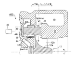
- FIG. 2 is a diagram illustrating a variable capacity mechanism 40A according to an embodiment.
- FIG. 3 is a diagram showing a variable capacity mechanism 40B according to another embodiment.
- the variable capacity mechanism 40 according to the embodiment of the present invention includes a nozzle vane that protrudes toward the nozzle portion 18 from at least one of the shroud side and the hub side of the nozzle portion 18. 42, and a nozzle wall 44 that is accommodated in a recess 56 formed on the hub side of the nozzle portion 18 and is movable forward and backward from the hub side of the nozzle portion 18 toward the shroud side, and the nozzle wall 44 is advanced and retracted.
- Driving means 46 to be operated.
- the nozzle vane 42 has a base end portion 43 fixed to the turbine housing 10 or the bearing housing 20 by welding or bolt fastening or the like, and protrudes from the nozzle portion 18 in a non-rotatable state.
- a plurality of nozzle vanes 42 are provided at intervals in the circumferential direction in the annular nozzle portion 18.
- the nozzle vane 42 projects from the shroud side toward the hub side.
- the nozzle vane 42 projects from the hub side of the nozzle portion 18 toward the shroud side.
- the nozzle wall 44 includes an annular flow guide wall portion 44 a that forms at least a part of the hub side flow guide wall 54 that defines the nozzle portion 18 with the shroud flow guide wall 52 of the turbine housing 10, and a flow guide wall.
- An opening 44d configured to allow the nozzle vane 42 to be inserted is formed in the flow guide wall 44a.
- reference numeral 12a denotes a turbine wheel hub
- reference numeral 12b denotes a moving blade provided on the hub 12a. In the embodiment shown in FIGS.
- the forward / backward direction of the nozzle wall 44 is from the hub side to the shroud side, but the present invention is not limited to this.
- the forward / backward direction of the nozzle wall 44 may be from the shroud side to the hub side.
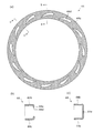
- FIG. 4A and 4B are views showing the nozzle wall 44.
- FIG. 4A is a plan view
- FIG. 4B is a bb cross-sectional view
- FIG. 4C is a cc cross-sectional view.
- the openings 44 d are formed at intervals in the circumferential direction corresponding to the installation positions of the nozzle vanes 42, and the openings 44 d are formed in the flow guide wall 44 a at locations where the nozzle vanes 42 are not installed. Is not formed.
- the opening shape of the opening 44d is similar to the cross-sectional shape of the nozzle vane 42 so that the gap between the opening vane 42 and the nozzle vane 42 is small.
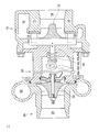
- FIG. 5 is a diagram showing the driving means 46 according to the embodiment.
- the driving means 46 urges the rod 46b in a direction to move the nozzle wall 44 to the hub side, an annular rear movable body 46a that advances and retracts the nozzle wall 44 from the rear side, a rod 46b that is connected to the rear movable body, and the nozzle wall 44 to the hub side.
- This rod 46b is arrange
- the nozzle wall 44 advances and retreats in the axial direction along the cam profile of the cam 46d.
- the nozzle width B defined as the width between the shroud side guide wall 52 and the hub side guide wall 54 of the nozzle portion 18 extends over the entire circumference of the annular nozzle portion 18. Change. And the flow of the exhaust gas which flows through the nozzle part 18 is controlled by the nozzle width B changing.
- the nozzle vane 42 is fixed to the nozzle portion 18 in a non-rotatable state, and only the nozzle wall 44 advances and retreats.
- the structure of a sliding part is simply comprised compared with the conventional variable capacity mechanism of a swing vane type or a slide vane type.
- the nozzle vane 42 is configured to protrude from the shroud-side flow guide wall 52 toward the nozzle portion 18, so that the nozzle vane 42 protrudes from the hub side where the recess 56 is formed. Also, the length of the nozzle vane 42 can be shortened.
- FIG. 6 is a diagram illustrating a cooling structure of the variable capacity mechanism 40 according to the embodiment.
- the shroud portion 15 of the turbine housing 10 is formed with an annular cooling passage 60 through which a cooling medium flows.
- a cooling medium such as water, oil, or air
- the shroud side guide wall 52 and the nozzle vane 42 protruding therefrom can be cooled. Therefore, for example, the nozzle vane 42 can be formed of normal inexpensive stainless steel without using an expensive material such as a heat-resistant Ni-based alloy for the nozzle vane 42.
- the cooling passage 60 is formed on the back surface of the base end portion 43 of the nozzle vane 42, a high cooling effect can be exerted on the nozzle vane 42.
- a cavity 62 communicating with the cooling passage 60 is formed inside the nozzle vane 42. According to such an embodiment, the nozzle vane 42 can be cooled more effectively.
- FIG. 7 is a diagram illustrating a cooling structure of the variable capacity mechanism 40 according to the embodiment.
- a through hole 64 is formed inside the nozzle vane 42 so as to penetrate the nozzle vane 42 in the axial direction.
- the through hole 64 communicates with the cooling passage 60 as shown in FIG. According to such an embodiment, the nozzle vane 42 is effectively cooled by the flow of a cooling medium such as air through the through hole 64.
- the shroud portion 15 of the turbine housing 10 is formed with a cooling medium discharge hole 66 that communicates the through hole 64 of the nozzle vane 42 and the exhaust outlet portion 14 downstream of the turbine wheel 12. . It is sufficient that at least one cooling medium discharge hole 66 is formed, and a plurality of cooling medium discharge holes 66 may be formed at intervals in the circumferential direction. According to such an embodiment, the cooling medium that has flowed through the through hole 64 is discharged to the exhaust outlet portion 14 on the downstream side of the turbine wheel 12 through the cooling medium discharge hole 66, so that the through hole 64 is continuously cooled. Media can be supplied.
- FIG. 8 is a diagram illustrating a nozzle wall 44 according to an embodiment.
- the variable capacity exhaust turbocharger 1 includes a nozzle wall surrounded by a flow guide wall portion 44a, an outer peripheral side wall portion 44b, and an inner peripheral side wall portion 44c.
- a cooling medium introduction mechanism 70 is provided for introducing the cooling medium into the internal space 44 f of 44.
- the nozzle wall 44 has an annular flange 44e that protrudes from the peripheral edge of the opening 44d toward the internal space 44f.
- the cooling medium can be introduced from the cooling medium introduction mechanism 70 into the internal space 44f of the nozzle wall 44, the nozzle wall 44 can be effectively cooled. Moreover, since the nozzle wall 44 has a flange portion 44e protruding from the peripheral edge of the opening portion 44d toward the hub side, the cooling medium introduced into the internal space 44f is difficult to leak into the nozzle portion 18, and cooling is performed. This prevents a decrease in turbine efficiency due to medium leakage.
- the cooling medium introduced into the internal space 44f flows through the through hole 64 inside the nozzle vane 42.
- the nozzle vanes 42 can be cooled.
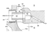
- FIG. 9 is a diagram illustrating a cooling medium introduction mechanism 70 according to an embodiment.
- the cooling medium introduction mechanism 70 is configured to introduce air flowing through the compressor housing 30 of the variable displacement exhaust turbocharger 1 as a cooling medium. Yes.
- the cooling medium introduction mechanism 70 has a refrigerant introduction pipe 72 that communicates between the intake scroll portion 36 of the compressor housing 30 and the recess 56 in which the nozzle wall 44 is accommodated, and the air compressed by the compressor wheel 32 is cooled by the cooling medium. It can be introduced into the internal space 44 f of the nozzle wall 44. According to such an embodiment, the air flowing through the compressor housing 30 can be used as the cooling medium with a simple structure.
- the cooling medium introduction mechanism 70 includes a control valve 74 as a pressure control means for controlling the pressure of air introduced into the internal space 44 f of the nozzle wall 44.
- a control valve 74 as a pressure control means for controlling the pressure of air introduced into the internal space 44 f of the nozzle wall 44.
- the air introduced from the intake scroll portion 36 has a higher pressure than the exhaust gas flowing through the nozzle portion 18. Therefore, the control valve 74 is configured as a pressure reducing valve 74, for example.
- variable displacement exhaust turbocharger 1 of this embodiment may include a control device that integrally controls the drive means 46 and the control valve 74.
- variable displacement exhaust turbocharger of at least one embodiment of the present invention is suitably used as a supercharger for an automobile engine, for example.
Abstract
Priority Applications (5)
| Application Number | Priority Date | Filing Date | Title |
|---|---|---|---|
| EP13875521.0A EP2960460A4 (fr) | 2013-02-21 | 2013-02-21 | Turbocompresseur à géométrie variable |
| CN201380070893.0A CN104937234A (zh) | 2013-02-21 | 2013-02-21 | 可变容量式排气涡轮增压机 |
| US14/764,917 US20150345376A1 (en) | 2013-02-21 | 2013-02-21 | Variable geometry exhaust gas turbocharger |
| JP2015501165A JPWO2014128894A1 (ja) | 2013-02-21 | 2013-02-21 | 可変容量型排気ターボ過給機 |
| PCT/JP2013/054402 WO2014128894A1 (fr) | 2013-02-21 | 2013-02-21 | Turbocompresseur à géométrie variable |
Applications Claiming Priority (1)
| Application Number | Priority Date | Filing Date | Title |
|---|---|---|---|
| PCT/JP2013/054402 WO2014128894A1 (fr) | 2013-02-21 | 2013-02-21 | Turbocompresseur à géométrie variable |
Publications (1)
| Publication Number | Publication Date |
|---|---|
| WO2014128894A1 true WO2014128894A1 (fr) | 2014-08-28 |
Family
ID=51390722
Family Applications (1)
| Application Number | Title | Priority Date | Filing Date |
|---|---|---|---|
| PCT/JP2013/054402 WO2014128894A1 (fr) | 2013-02-21 | 2013-02-21 | Turbocompresseur à géométrie variable |
Country Status (5)
| Country | Link |
|---|---|
| US (1) | US20150345376A1 (fr) |
| EP (1) | EP2960460A4 (fr) |
| JP (1) | JPWO2014128894A1 (fr) |
| CN (1) | CN104937234A (fr) |
| WO (1) | WO2014128894A1 (fr) |
Cited By (3)
| Publication number | Priority date | Publication date | Assignee | Title |
|---|---|---|---|---|
| KR102034493B1 (ko) * | 2018-07-06 | 2019-10-22 | 클러스터엘앤지(주) | 재액화 시스템용 팽창터빈 |
| JP2021105370A (ja) * | 2019-12-26 | 2021-07-26 | トヨタ自動車株式会社 | 過給機 |
| WO2021199308A1 (fr) * | 2020-03-31 | 2021-10-07 | 三菱重工エンジン&ターボチャージャ株式会社 | Turbocompresseur |
Families Citing this family (16)
| Publication number | Priority date | Publication date | Assignee | Title |
|---|---|---|---|---|
| GB201408087D0 (en) * | 2014-05-07 | 2014-06-18 | Cummins Ltd | Variable geometry turbine assembly |
| WO2017078088A1 (fr) * | 2015-11-06 | 2017-05-11 | カルソニックカンセイ株式会社 | Carter de turbine |
| US9739166B1 (en) * | 2016-08-31 | 2017-08-22 | Borgwarner Inc. | VTG internal by-pass |
| GB2555872A (en) | 2016-11-15 | 2018-05-16 | Cummins Ltd | Vane arrangement for a turbo-machine |
| US20190301358A1 (en) * | 2016-12-01 | 2019-10-03 | Man Energy Solutions Se | Turbocharger |
| GB2578270B (en) * | 2018-05-15 | 2022-06-29 | Cummins Ltd | Vanes and shrouds for a turbo-machine |
| US11697997B2 (en) * | 2018-05-15 | 2023-07-11 | Cummins Ltd. | Vanes and shrouds for a turbo-machine |
| GB2574195B (en) * | 2018-05-15 | 2022-06-08 | Cummins Ltd | Vane and shroud arrangements for a turbo-machine |
| DE112019003298B4 (de) | 2018-06-29 | 2022-12-01 | Ihi Corporation | Turbine und Turbolader |
| US10907497B2 (en) | 2018-12-13 | 2021-02-02 | Transportation Ip Holdings, Llc | Method and systems for a variable geometry turbocharger for an engine |
| WO2020174551A1 (fr) * | 2019-02-25 | 2020-09-03 | 三菱重工エンジン&ターボチャージャ株式会社 | Injecteur |
| CN110578562B (zh) * | 2019-08-30 | 2023-08-29 | 上海齐耀动力技术有限公司 | 一种冷却结构及其连接结构 |
| US11371374B2 (en) * | 2020-07-22 | 2022-06-28 | Raytheon Technologies Corporation | Seal runner flow damper |
| US11686210B2 (en) * | 2021-03-24 | 2023-06-27 | General Electric Company | Component assembly for variable airfoil systems |
| DE102021204711A1 (de) | 2021-05-10 | 2022-11-10 | Vitesco Technologies GmbH | Turboladereinrichtung |
| CN114307462B (zh) * | 2021-12-02 | 2023-12-15 | 鄂托克旗红缨煤焦化有限责任公司 | 一种焦化烟气与含氨废水一体化处理系统 |
Citations (9)
| Publication number | Priority date | Publication date | Assignee | Title |
|---|---|---|---|---|
| JPS56129705A (en) * | 1980-02-22 | 1981-10-12 | Holset Engineering Co | Radial inward flow turbine |
| JPS6185503A (ja) * | 1984-10-04 | 1986-05-01 | Mitsubishi Heavy Ind Ltd | 輻流タ−ボ機械 |
| JPH05214949A (ja) * | 1992-01-31 | 1993-08-24 | Mitsubishi Heavy Ind Ltd | 可変容量過給機 |
| JPH11350967A (ja) * | 1998-06-12 | 1999-12-21 | Toyota Motor Corp | 排気絞り用可変ノズルベーン付きターボチャージャ |
| WO2007031752A1 (fr) * | 2005-09-15 | 2007-03-22 | Malcolm George Leavesley | Appareil turbocompresseur variable avec moyens de dérivation destinés à dériver des gaz d’échappement |
| JP2008133924A (ja) | 2006-11-29 | 2008-06-12 | Komatsu Ltd | シルティング防止制御装置および方法 |
| JP2008196452A (ja) * | 2007-02-15 | 2008-08-28 | Toyota Industries Corp | 可変容量型ターボチャージャ |
| JP2008544126A (ja) * | 2005-06-11 | 2008-12-04 | ダイムラー・アクチェンゲゼルシャフト | 排気ターボチャージャの排気タービン |
| JP2010540819A (ja) * | 2007-09-28 | 2010-12-24 | ダイムラー・アクチェンゲゼルシャフト | 内燃機関の排気ガスターボチャージャ |
Family Cites Families (11)
| Publication number | Priority date | Publication date | Assignee | Title |
|---|---|---|---|---|
| GB1138941A (en) * | 1965-01-15 | 1969-01-01 | Stuart Swinford Wilson | Improvements in and relating to radial flow turbines |
| EP0095853B1 (fr) * | 1982-05-28 | 1988-08-03 | Holset Engineering Company Limited | Turbine avec section d'admission variable |
| JPS6119602U (ja) * | 1984-07-10 | 1986-02-04 | トヨタ自動車株式会社 | タ−ボチヤ−ジヤのノズルベ−ン冷却装置 |
| US4611969A (en) * | 1985-08-19 | 1986-09-16 | Carrier Corporation | Calibrating apparatus and method for a movable diffuser wall in a centrifugal compressor |
| JPH0346186Y2 (fr) * | 1985-10-31 | 1991-09-30 | ||
| JPS6434404U (fr) * | 1987-08-25 | 1989-03-02 | ||
| GB2218745B (en) * | 1988-05-17 | 1992-07-01 | Holset Engineering Co | Variable geometry turbine actuator assembly |
| ITTO20010505A1 (it) * | 2001-05-25 | 2002-11-25 | Iveco Motorenforschung Ag | Turbina a geometria variabile. |
| JP2009243277A (ja) * | 2008-03-28 | 2009-10-22 | Toyota Motor Corp | タービンハウジング冷却システム |
| KR20120105055A (ko) * | 2010-02-25 | 2012-09-24 | 가부시키가이샤 아이에이치아이 | 가변 용량형 터보 차저 |
| CN102782293B (zh) * | 2010-03-01 | 2014-06-25 | 株式会社小松制作所 | 内燃机的供气控制装置及供气控制方法 |
-
2013
- 2013-02-21 EP EP13875521.0A patent/EP2960460A4/fr not_active Withdrawn
- 2013-02-21 JP JP2015501165A patent/JPWO2014128894A1/ja active Pending
- 2013-02-21 CN CN201380070893.0A patent/CN104937234A/zh active Pending
- 2013-02-21 US US14/764,917 patent/US20150345376A1/en not_active Abandoned
- 2013-02-21 WO PCT/JP2013/054402 patent/WO2014128894A1/fr active Application Filing
Patent Citations (9)
| Publication number | Priority date | Publication date | Assignee | Title |
|---|---|---|---|---|
| JPS56129705A (en) * | 1980-02-22 | 1981-10-12 | Holset Engineering Co | Radial inward flow turbine |
| JPS6185503A (ja) * | 1984-10-04 | 1986-05-01 | Mitsubishi Heavy Ind Ltd | 輻流タ−ボ機械 |
| JPH05214949A (ja) * | 1992-01-31 | 1993-08-24 | Mitsubishi Heavy Ind Ltd | 可変容量過給機 |
| JPH11350967A (ja) * | 1998-06-12 | 1999-12-21 | Toyota Motor Corp | 排気絞り用可変ノズルベーン付きターボチャージャ |
| JP2008544126A (ja) * | 2005-06-11 | 2008-12-04 | ダイムラー・アクチェンゲゼルシャフト | 排気ターボチャージャの排気タービン |
| WO2007031752A1 (fr) * | 2005-09-15 | 2007-03-22 | Malcolm George Leavesley | Appareil turbocompresseur variable avec moyens de dérivation destinés à dériver des gaz d’échappement |
| JP2008133924A (ja) | 2006-11-29 | 2008-06-12 | Komatsu Ltd | シルティング防止制御装置および方法 |
| JP2008196452A (ja) * | 2007-02-15 | 2008-08-28 | Toyota Industries Corp | 可変容量型ターボチャージャ |
| JP2010540819A (ja) * | 2007-09-28 | 2010-12-24 | ダイムラー・アクチェンゲゼルシャフト | 内燃機関の排気ガスターボチャージャ |
Non-Patent Citations (1)
| Title |
|---|
| See also references of EP2960460A4 * |
Cited By (3)
| Publication number | Priority date | Publication date | Assignee | Title |
|---|---|---|---|---|
| KR102034493B1 (ko) * | 2018-07-06 | 2019-10-22 | 클러스터엘앤지(주) | 재액화 시스템용 팽창터빈 |
| JP2021105370A (ja) * | 2019-12-26 | 2021-07-26 | トヨタ自動車株式会社 | 過給機 |
| WO2021199308A1 (fr) * | 2020-03-31 | 2021-10-07 | 三菱重工エンジン&ターボチャージャ株式会社 | Turbocompresseur |
Also Published As
| Publication number | Publication date |
|---|---|
| US20150345376A1 (en) | 2015-12-03 |
| JPWO2014128894A1 (ja) | 2017-02-02 |
| EP2960460A4 (fr) | 2016-03-09 |
| CN104937234A (zh) | 2015-09-23 |
| EP2960460A1 (fr) | 2015-12-30 |
Similar Documents
| Publication | Publication Date | Title |
|---|---|---|
| WO2014128894A1 (fr) | Turbocompresseur à géométrie variable | |
| US10125673B2 (en) | Variable nozzle unit and variable geometry turbocharger | |
| JP5710452B2 (ja) | ターボチャージャ | |
| JPS62139931A (ja) | タ−ボチヤ−ジヤ | |
| CN102459823A (zh) | 壳体的部件,尤其是涡轮机的壳体的部件 | |
| CN102434229A (zh) | 可变几何涡轮机 | |
| EP2325454A1 (fr) | Turbocompresseur équipé de dispositif à géométrie variable | |
| KR101244956B1 (ko) | 실링 에어 채널을 가진 안내 장치의 캐리어 링 | |
| JP2010001863A (ja) | ターボチャージャ | |
| JP2005535836A (ja) | 内燃エンジン用排気ガスターボチャージャー | |
| JP5141405B2 (ja) | ターボチャージャ | |
| JP2013253519A (ja) | 可変ノズルユニット及び可変容量型過給機 | |
| JP5747403B2 (ja) | ターボ回転機械及びその運転方法 | |
| JP2008095613A (ja) | 過給機 | |
| JP2014530992A (ja) | バルブ、特に自動車エンジン用バルブ | |
| GB2473274A (en) | Variable geometry turbine | |
| JP5989129B2 (ja) | 排気ガスターボチャージャーのタービン | |
| JP6146507B2 (ja) | 可変ノズルユニット及び可変容量型過給機 | |
| JP2010163951A (ja) | 自動車用排気タービン発電装置 | |
| JP2014047726A (ja) | タービンハウジング及び排気タービン過給機 | |
| RU2484259C1 (ru) | Система регулирования расхода воздуха на охлаждение турбины газотурбинного двигателя | |
| CN108442981B (zh) | 一种双活塞环可变喷嘴组件 | |
| JP2015504135A (ja) | 排気ガスターボチャージャー | |
| JP6099987B2 (ja) | 可変容量タービン及びこれを備えた過給機並びに可変容量タービンの制御方法 | |
| JP2002070568A (ja) | 排気タービン過給機 |
Legal Events
| Date | Code | Title | Description |
|---|---|---|---|
| 121 | Ep: the epo has been informed by wipo that ep was designated in this application |
Ref document number: 13875521 Country of ref document: EP Kind code of ref document: A1 |
|
| ENP | Entry into the national phase |
Ref document number: 2015501165 Country of ref document: JP Kind code of ref document: A |
|
| REEP | Request for entry into the european phase |
Ref document number: 2013875521 Country of ref document: EP |
|
| WWE | Wipo information: entry into national phase |
Ref document number: 2013875521 Country of ref document: EP |
|
| WWE | Wipo information: entry into national phase |
Ref document number: 14764917 Country of ref document: US |
|
| NENP | Non-entry into the national phase |
Ref country code: DE |