WO2014119583A1 - 電解銅箔、該電解銅箔を用いた電池用集電体、該集電体を用いた二次電池用電極、該電極を用いた二次電池 - Google Patents
電解銅箔、該電解銅箔を用いた電池用集電体、該集電体を用いた二次電池用電極、該電極を用いた二次電池 Download PDFInfo
- Publication number
- WO2014119583A1 WO2014119583A1 PCT/JP2014/051861 JP2014051861W WO2014119583A1 WO 2014119583 A1 WO2014119583 A1 WO 2014119583A1 JP 2014051861 W JP2014051861 W JP 2014051861W WO 2014119583 A1 WO2014119583 A1 WO 2014119583A1
- Authority
- WO
- WIPO (PCT)
- Prior art keywords
- copper foil
- electrolytic copper
- tungsten
- electrolytic
- foil
- Prior art date
- Legal status (The legal status is an assumption and is not a legal conclusion. Google has not performed a legal analysis and makes no representation as to the accuracy of the status listed.)
- Ceased
Links
Classifications
-
- C—CHEMISTRY; METALLURGY
- C22—METALLURGY; FERROUS OR NON-FERROUS ALLOYS; TREATMENT OF ALLOYS OR NON-FERROUS METALS
- C22C—ALLOYS
- C22C9/00—Alloys based on copper
-
- C—CHEMISTRY; METALLURGY
- C22—METALLURGY; FERROUS OR NON-FERROUS ALLOYS; TREATMENT OF ALLOYS OR NON-FERROUS METALS
- C22F—CHANGING THE PHYSICAL STRUCTURE OF NON-FERROUS METALS AND NON-FERROUS ALLOYS
- C22F1/00—Changing the physical structure of non-ferrous metals or alloys by heat treatment or by hot or cold working
- C22F1/08—Changing the physical structure of non-ferrous metals or alloys by heat treatment or by hot or cold working of copper or alloys based thereon
-
- C—CHEMISTRY; METALLURGY
- C25—ELECTROLYTIC OR ELECTROPHORETIC PROCESSES; APPARATUS THEREFOR
- C25D—PROCESSES FOR THE ELECTROLYTIC OR ELECTROPHORETIC PRODUCTION OF COATINGS; ELECTROFORMING; APPARATUS THEREFOR
- C25D1/00—Electroforming
- C25D1/04—Wires; Strips; Foils
-
- H—ELECTRICITY
- H01—ELECTRIC ELEMENTS
- H01M—PROCESSES OR MEANS, e.g. BATTERIES, FOR THE DIRECT CONVERSION OF CHEMICAL ENERGY INTO ELECTRICAL ENERGY
- H01M10/00—Secondary cells; Manufacture thereof
- H01M10/05—Accumulators with non-aqueous electrolyte
- H01M10/052—Li-accumulators
-
- H—ELECTRICITY
- H01—ELECTRIC ELEMENTS
- H01M—PROCESSES OR MEANS, e.g. BATTERIES, FOR THE DIRECT CONVERSION OF CHEMICAL ENERGY INTO ELECTRICAL ENERGY
- H01M4/00—Electrodes
- H01M4/02—Electrodes composed of, or comprising, active material
- H01M4/64—Carriers or collectors
- H01M4/66—Selection of materials
- H01M4/661—Metal or alloys, e.g. alloy coatings
- H01M4/662—Alloys
-
- C—CHEMISTRY; METALLURGY
- C25—ELECTROLYTIC OR ELECTROPHORETIC PROCESSES; APPARATUS THEREFOR
- C25D—PROCESSES FOR THE ELECTROLYTIC OR ELECTROPHORETIC PRODUCTION OF COATINGS; ELECTROFORMING; APPARATUS THEREFOR
- C25D3/00—Electroplating: Baths therefor
- C25D3/02—Electroplating: Baths therefor from solutions
- C25D3/38—Electroplating: Baths therefor from solutions of copper
-
- Y—GENERAL TAGGING OF NEW TECHNOLOGICAL DEVELOPMENTS; GENERAL TAGGING OF CROSS-SECTIONAL TECHNOLOGIES SPANNING OVER SEVERAL SECTIONS OF THE IPC; TECHNICAL SUBJECTS COVERED BY FORMER USPC CROSS-REFERENCE ART COLLECTIONS [XRACs] AND DIGESTS
- Y02—TECHNOLOGIES OR APPLICATIONS FOR MITIGATION OR ADAPTATION AGAINST CLIMATE CHANGE
- Y02E—REDUCTION OF GREENHOUSE GAS [GHG] EMISSIONS, RELATED TO ENERGY GENERATION, TRANSMISSION OR DISTRIBUTION
- Y02E60/00—Enabling technologies; Technologies with a potential or indirect contribution to GHG emissions mitigation
- Y02E60/10—Energy storage using batteries
Definitions
- the present invention relates to an electrolytic copper foil having a low profile electrolytic deposition surface, high mechanical strength, and hardly changing mechanical strength even when heated at a high temperature.
- the present invention relates to a secondary battery in which the electrolytic copper foil is used as a current collector for a secondary battery, an active material is deposited on the current collector to form an electrode for a secondary battery, and the electrode is incorporated.
- the electrolytic copper foil of the present invention can be suitably used for rigid printed wiring boards, flexible printed wiring boards, electromagnetic wave shielding materials, and the like using the electrolytic copper foil as a conductive material.
- electrolytic copper foil and electrolytic copper alloy foil are distinguished and expressed.
- electrolytic copper foil a foil containing an alloy of copper and a third metal in the foil, a foil containing the third metal in a solid solution state in the foil.
- Copper foil is used in various fields such as rigid printed wiring boards, flexible printed wiring boards, electromagnetic shielding materials, and battery current collectors.
- the suspension mounted in the HDD is a wiring-integrated suspension in which the flying head buoyancy and the positional accuracy are stable with respect to the disk as the storage medium from the wire type suspension that has been used conventionally as the capacity of the HDD increases. The majority have been replaced.
- This wiring-integrated suspension has the following three types. a. A type in which a flexible printed circuit board called FSA (flex suspension assembly) method is processed and bonded using an adhesive b. Type C.TSA (Trace Suspension / Assembly) type called stainless steel foil-polyimide resin-copper foil laminated body processed into a predetermined shape by etching
- the TSA suspension allows easy formation of flying leads by laminating copper alloy foils with high strength, has a high degree of freedom in shape processing, and is relatively inexpensive and has good dimensional accuracy. Widely used.
- the laminate formed by the TSA method is manufactured using a material having a stainless steel foil thickness of about 12 to 30 ⁇ m, a polyimide layer thickness of about 5 to 20 ⁇ m, and a copper alloy foil thickness of about 7 to 14 ⁇ m.
- the stainless steel foil hardly changes in dimensions.
- the electrolytic copper foil is annealed at a temperature of about 300 ° C., recrystallization proceeds, softens, and a dimensional change occurs. For this reason, the laminate is warped after lamination, and the dimensional accuracy of the product is lowered.
- provision of a copper alloy foil that is as small as possible in dimensional change during heating is required.
- the TAB material As with the HDD suspension material, it is required to increase the strength of the copper foil and reduce the roughness of the foil surface.
- a TAB product a plurality of terminals of an IC chip are directly bonded to inner leads (flying leads) arranged in a device hole located substantially at the center of the product. This bonding is performed by applying a constant bonding pressure by instantaneously energizing and heating using a bonding apparatus.
- the inner lead obtained by etching the electrolytic copper foil is stretched by being pulled by the bonding pressure.
- the inner lead may sag due to plastic deformation and may break if it is significant. Therefore, in order to reduce the line width of the inner lead, the electrolytic copper foil to be used is required to have a roughened surface with low roughness and to have high strength.
- the copper foil has high strength in a normal state (normal temperature / normal pressure state) and has high strength even after being heated.
- a two-layer or three-layer FPC in which a copper foil and a polyimide are bonded together is used.
- an epoxy adhesive is used and the bonding is performed at a temperature of about 180 ° C.
- bonding is performed at a temperature of about 300 ° C.
- electrolytic copper foil Even if the electrolytic copper foil has a high mechanical strength in the normal state, it does not make sense if the electrolytic copper foil softens when bonded to polyimide.
- Conventional high-strength electrolytic copper foil has high mechanical strength in the normal state, and the mechanical strength hardly changes even when heated at around 180 ° C. However, when heated at about 300 ° C, it is annealed and recrystallization proceeds. , It softens rapidly and the mechanical strength decreases. Such a copper foil is not suitable for TAB applications.
- the copper foil is used as a current collector for a battery such as a lithium ion secondary battery.
- a lithium ion secondary battery is basically composed of a positive electrode, a negative electrode, and an electrolytic solution.
- the negative electrode is formed by coating the surface of a copper foil used as a current collector with a negative electrode active material layer.
- a method for forming the negative electrode a slurry obtained by dissolving a negative electrode active material and a binder resin (added for the purpose of binding the active material and the copper foil substrate) in a solvent is applied onto the copper foil substrate, and then the binder resin is formed.
- a method of forming by pressing after drying at a temperature equal to or higher than the curing temperature is generally used.
- the binder resin polyvinylidene fluoride (PVDF), styrene butadiene rubber (SBR) and the like are widely used.
- PVDF polyvinylidene fluoride
- SBR styrene butadiene rubber
- the above-mentioned binder resin is large and lacks strength. Therefore, a polyimide resin having a high adhesive strength with a copper substrate has been preferably used.
- the polyimide resin has a very high curing temperature of about 300 ° C., and a negative electrode current collector (copper foil) that can withstand this heating condition is required.
- a polyimide resin having a very high curing temperature of about 300 ° C. has been used as a binder, and a copper foil that can withstand this heating condition is required. ing.
- an electrolytic solution containing copper sulfate and sulfuric acid is used as the electrolytic solution for the electrolytic copper foil, and various additions are made to the plating bath for the purpose of making the copper foil surface bright and smooth, reducing the stress of the copper foil, etc.
- An agent has been added.
- the additive is not used, the surface form and mechanical properties required for the copper foil cannot be obtained, so the additive is very important.
- the copper sulfate plating bath is a simple acidic bath, it is inferior in throwing power and it is difficult to produce a preferable electrolytic copper foil without an additive.
- additives used in copper sulfate plating baths chlorine ions, polyoxyethylene surfactants, smoothing agents, brighteners such as organic sulfides, glue, gelatin, etc. have been proposed and used. .
- Plating concentrates on high current areas where electricity can easily flow without adding chlorine or additives to the copper sulfate plating bath (locations close to the anode, the end of the cathode, the tip of sharp objects, etc.) State (plated surface becomes more uneven). Therefore, chlorine ions are added in normal copper sulfate plating.
- Patent Documents 1 and 2 disclose a method for producing an electrolytic copper foil with an electrolytic solution in which tungsten is added to a sulfuric acid-copper sulfate electrolytic solution and further glue and chloride ions are added. It describes that it is possible to produce a copper foil having a hot elongation rate of 3% or more, a rough surface having a large roughness and less pinholes.
- the present inventors have repeatedly conducted an experiment in which tungsten is added to a sulfuric acid-copper sulfate electrolytic solution, and glue and chloride ions are further added, and the electrolytic copper foil disclosed in Patent Document 1 has a target heat at 180 ° C. It was possible to produce a copper foil having an interstitial elongation of 3% or more, a large rough surface, and few pinholes. However, when this copper foil was heat-treated at 300 ° C. for 1 hour, it was found that the mechanical strength could not be maintained. Therefore, when this copper foil was analyzed, it was found that tungsten was not co-deposited in the electrodeposited copper.
- the electrolytic copper foil is made by adding chlorine and an organic compound as additives to an electrolytic solution containing copper sulfate and sulfuric acid.
- Many organic additives usually have an effect of suppressing crystal growth, and are considered to be taken into crystal grain boundaries. In this case, the mechanical strength tends to improve as the amount of the organic additive incorporated into the crystal grain boundary increases (Non-patent Document 1: Shoji Shiga; Metal Surface Technology Vol31, No10, p573 (1980)).
- the organic additive incorporated in the electrolytic copper foil improves the mechanical strength of the copper foil. This factor can be considered that the organic additive is mainly taken into the crystal grain boundary and improves the mechanical strength at room temperature.
- the electrolytic copper foil incorporating the organic additive is heated at a high temperature of 300 ° C. or higher, the mechanical strength decreases. The cause is presumed that the organic additive is thermally decomposed, resulting in a decrease in mechanical strength.
- a rolled copper alloy foil is used as a copper foil that satisfies the above requirements.
- the rolled copper alloy foil is not easily annealed at a temperature of about 300 ° C., has little dimensional change during heating, and little mechanical strength change.
- rolled copper foil is more expensive than electrolytic copper foil, and it is difficult to satisfy requirements such as width and thickness.
- the present inventors have a low profile surface bonded to the polyimide resin base material, and excellent mechanical strength, and as an electrolytic copper foil suitable for use with a polyimide resin as a binder resin, Various metals were added to the copper foil to try to improve its heat resistance.
- a metal capable of improving the heat resistance of the copper foil into the electrolytic copper foil. That is, the metal that improves the heat resistance of the copper foil is a metal that is very difficult to incorporate into the copper foil.
- the present inventors have made it possible to use a polyimide binder as an HDD suspension material, a TAB material, or an active material that repeats large expansion and contraction of a Si or Sn alloy-based active material.
- a polyimide binder as an HDD suspension material, a TAB material, or an active material that repeats large expansion and contraction of a Si or Sn alloy-based active material.
- electrolytic copper foil that does not deform as (copper foil).
- An object of the present invention is to provide an electrolytic copper foil having a tensile strength of 500 MPa or more measured at room temperature after heat treatment at 300 ° C. for 1 hour. Another object of the present invention is to provide an electrolytic copper foil having excellent mechanical strength in applications in the field of printed wiring boards bonded to polyimide films. Furthermore, the present invention is a lithium ion secondary battery using a Si or Sn alloy-based active material, and adheres between the current collector (copper foil) and the active material against large expansion and contraction of the Si or Sn alloy-based active material It is an object to provide a copper foil that retains its properties with a polyimide binder and does not deform or break the current collector (copper foil).
- the electrolytic copper foil of the present invention contains 0.06 wt% or more of tungsten. More preferably, the tungsten content of the electrolytic copper foil of the present invention is 0.06 wt% to 0.5 wt%.
- the electrolytic copper foil of the present invention contains 0.06 wt% to 0.5 wt% of tungsten and 0.001 wt% to 0.07 wt% of chlorine. Preferably, all or part of the tungsten is incorporated as an oxide.
- the electrolytic copper foil contains tungsten and the balance is substantially made of copper.
- the balance is substantially made of copper means that copper contains inevitable impurities derived from raw materials or the like, or allows a trace amount of additive by an electrolytic foil making process or the like to be contained, It means that.
- the electrolytic copper foil of the present invention contains 0.06 wt% to 0.5 wt% of tungsten, and has a tensile strength of 500 MPa or more measured at room temperature after heat treatment at 300 ° C. for 1 hour.
- the electrolytic copper foil of the present invention contains 0.06 wt% to 0.5 wt% of tungsten, 0.001 wt% to 0.07 wt% of chlorine, and is measured at room temperature after heat treatment at 300 ° C. for 1 hour.
- the strength is 500 MPa or more.
- the current collector for a secondary battery of the present invention is characterized by using the electrolytic copper foil described above.
- the electrode for a secondary battery of the present invention is characterized in that the electrolytic copper foil described above is used as a current collector for a secondary battery, and an active material is deposited on the surface thereof.
- the secondary battery of the present invention is a secondary battery using the secondary battery electrode.
- an electrolytic copper foil that has high mechanical strength in the normal state and that hardly undergoes thermal deterioration even when heated at 300 ° C. or higher.
- the electrolytic copper foil of the present invention is an electrolytic copper foil containing tungsten and the balance being copper.
- the amount of tungsten contained in the electrolytic copper foil is 0.06 wt% or more, more preferably 0.06 wt% to 0.5 wt%.
- the reason why the tungsten content is 0.06 wt% or more is that the tensile strength measured at room temperature after heat treatment at 300 ° C. for 1 hour is improved as compared with a copper foil having a content of 0.06 wt% or less. This is because the cycle life of the battery is increased by using it as an electric body.
- the added amount of tungsten is preferably 0.5 wt% or less is that the effect is saturated even if it is added more than 0.5 wt%, and the effect of improving the physical properties is hardly seen. Moreover, it also causes a decrease in conductivity, which is not preferable.
- the present inventors repeated various experiments in order to produce an electrolytic copper foil containing W.
- an electrolytic solution containing chlorine ions even if a large amount of tungsten is added to the solution, tungsten is not taken into the formed copper foil, and naturally the copper foil formed with such an electrolytic solution is used.
- the mechanical strength of the foil after heating at normal temperature and after heating was not improved.
- chlorine ions were added to the electrolytic solution, it was found that if a thiourea compound was added to the solution, tungsten was taken into the foil depending on the foil-making conditions.
- the electrolytic copper foil of the present invention contains 0.06 wt% to 0.5 wt% tungsten and 0.001 wt% to 0.07 wt% chlorine.
- the reason why the chlorine content is 0.001 wt% or more is that when the content is 0.001 wt% or less, the surface smoothness of the copper foil surface is lost.
- the reason why the chlorine content is 0.07 wt% or less is that when 0.07 wt% or more is contained, the initial strength of the electrolytic copper foil produced tends to be reduced, and the initial strength is decreased to reduce the initial strength. It is because the intensity
- Additives added to the sulfuric acid-copper sulfate-based copper electrolyte are as follows.
- Additive A: Thiourea compound 2 to 20 mg / L
- Additive B: Tungsten salt (as tungsten) 150 to 1,000 mg / L
- Additive C: Chlorine ion 5 to 70 mg / L
- the additive B means “tungsten salt in an amount corresponding to 150 to 1,000 mg / L as tungsten metal” (the same applies hereinafter).
- Tungsten salt dissolves in an electrolytic solution containing copper sulfate and sulfuric acid, and examples thereof include sodium tungstate, ammonium tungstate, and potassium tungstate.
- Additive C The addition of chloride ions is selected from compounds that dissolve in an electrolytic solution containing copper sulfate and sulfuric acid. Examples include hydrochloric acid, sodium chloride, and potassium chloride.
- Tungsten exists as an oxide in an acidic solution, but in copper electrodeposition using an electrolytic solution containing chlorine, since the chloride ion coats the copper deposition surface, tungsten oxide is not adsorbed on copper, No uptake of tungsten into the foil.
- the electrolytic copper foil of the present invention is formed by electrolytic deposition from an electrolytic solution containing tungsten, a thiourea compound, and chlorine in a sulfuric acid-copper sulfate electrolytic solution.
- tungsten oxide is adsorbed along with the thiourea compounds together with copper grain boundaries, and crystal nuclei grow. It is considered that an electrolytic copper foil having a large mechanical strength is formed in a normal state by suppressing the above-described phenomenon and making the crystal grains fine (low profile).
- the electrolytic copper foil containing tungsten is heated at a high temperature of about 300 ° C., the tungsten oxide stays at the crystal grain boundary, and the fine crystal of copper is recrystallized by heat to prevent the crystal from becoming coarse. It is thought to work.
- the electrolytic copper foil of the present invention is a sulfuric-copper sulfate-based electrolytic solution using a conventional organic additive that has a low profile and a small decrease in mechanical strength even after heating at a high temperature of about 300 ° C. Exhibits excellent characteristics not found in electrolytic copper foil.
- the thiourea compound added to the sulfuric acid-copper sulfate electrolytic solution forms a complex with the metal element and chlorine in the electrolytic solution.
- the metal element added to the electrolytic solution for making an electrolytic copper foil is copper. Accordingly, a copper-thiourea compound is formed in an electrolytic solution containing copper sulfate and sulfuric acid.
- the copper-thiourea compound is adsorbed on the grain boundaries, suppressing the growth of crystal nuclei, making the grains finer, and increasing the mechanical strength in the normal state.
- the provided electrolytic copper foil is formed.
- this copper foil is a copper-thiourea compound that exists at the grain boundaries, copper is bound to or absorbed by bulk copper crystals, and the substance present at the grain boundaries is the thiourea compound. Therefore, it is considered that when it is exposed to a high temperature of about 300 ° C., it decomposes and as a result, the mechanical strength decreases.
- the reason why the tensile strength is remarkably lowered when heated at a high temperature of about 300 ° C. is that the compound existing at the crystal grain boundary is an organic compound as described above, and the organic compound is easily decomposed by heating at about 300 ° C. Therefore, it is considered that the mechanical strength decreases.
- electrolytic deposition is performed using different organic compounds to produce an electrolytic copper foil, both of which are sulfuric acid-copper sulfate electrolytes containing an organic additive and chlorine. Since it is an organic compound component that is adsorbed to the crystal grain boundary of the electrolytic copper foil, when such an electrolytic copper foil is exposed to a high temperature of 300 ° C. or more, the mechanical strength is remarkably increased. The reason for the decrease is considered to be that any of the compounds adsorbed on the grain boundaries are organic compounds that are easily decomposed by heating at a high temperature of 300 ° C. or higher.
- the present invention performs copper electrodeposition on an electrolytic solution containing copper sulfate and sulfuric acid with an electrolytic solution containing tungsten, a thiourea compound, and chlorine to form a copper alloy foil.
- the adsorbed tungsten oxide and thiourea compound suppress the growth of crystal nuclei, refine the crystal grains, and form an electrolytic copper foil having a large mechanical strength in a normal state.
- tungsten oxide and thiourea compounds are present at the grain boundaries, so that unlike the case of copper-thiourea compounds, tungsten oxide bonds with bulk copper crystals.
- the tungsten oxide and the thiourea compound remain at the grain boundary without being absorbed. For this reason, even when exposed to a high temperature of about 300 ° C., tungsten oxide stays at the crystal grain boundary and functions to prevent the fine crystal of copper from being recrystallized by heat and coarsening of the crystal.
- the addition of a thiourea compound succeeded in incorporating tungsten into the copper foil.
- the amount of the thiourea compound to be added is 2 mg / L to 20 mg / L. If the amount is less than 2 mg / L, the prescribed amount of tungsten cannot be taken into the copper foil, and the tensile strength after heat treatment at 300 ° C. ⁇ 1 hour The strength decreases, and if added over 20 mg / L, warpage (curl) becomes strong in the state of the foil, so the addition amount is preferably in the range of 2 mg / L to 20 mg / L.
- the amount of chlorine ion added is 5 to 70 mg / L. Addition of less than 5 mg / L of chlorine ions is not preferable because defects such as markedly increased surface roughness (impairing the smoothness of the surface) occur, and adding more than 70 mg / L of chloride ions will result in a foil. This is not preferable because the initial strength is reduced. Accordingly, the chlorine ion to be added is preferably in the range of 5 to 70 mg / L, particularly preferably 10 to 30 mg / L.
- the electrolytic copper foil has a current density of 30 to 30 with a copper sulfate solution containing the above-mentioned prescribed amounts of tungsten, thiourea compound, and chlorine ions as an electrolyte, noble metal oxide-coated titanium as an anode, and a titanium rotating drum as a cathode.
- Foil is made by electrolytic treatment under the conditions of 100 A / dm 2 and a liquid temperature of 30 to 70 ° C.
- the current collector (copper foil) constituting the negative electrode current collector of a lithium ion secondary battery usually needs to withstand heat treatment at 300 ° C. for 1 hour. That is, an active material composition prepared by adding a solvent to a mixture of an active material, a conductive material and a binder to a surface of a current collector for a lithium ion secondary battery and applying a lithium ion secondary battery through a drying process. It is used as an electrode for a secondary battery. In the drying process, a heat treatment of 300 ° C. ⁇ 1 hour is required.
- a condition that the tensile strength measured at room temperature after heat treatment at 300 ° C. for 1 hour is 500 MPa or more. Satisfactory performance is required.
- the tungsten-containing electrolytic copper foil of the present invention satisfies various characteristics required by the current collector for a secondary battery. Therefore, such an electrolytic copper foil is used as a current collector, and silicon, germanium, tin, or an alloy compound thereof or an active material containing them as a main component is deposited on the current collector as an electrode. An excellent lithium ion secondary battery can be manufactured.
- the electrolytic copper foil of the present invention is particularly excellent as a current collector of a lithium ion secondary battery, but it is needless to say that it can be suitably used as a current collector for electrodes of other batteries.
- Examples 1-1 to 1--7 Using an electrolyte containing copper, sulfuric acid, chloride ions, tungsten, and thiourea organic additives in the amounts shown in Table 1 and an electrolyte containing sulfuric acid, the titanium rotating drum made of titanium is coated with noble metal oxide-coated titanium. As a cathode, an electrolytic copper foil was made under the following electrolysis conditions. Electrolytic condition current density 40A / dm 2 Temperature 45 ° C
- the electrolytic copper foil thus formed was subjected to a rust prevention treatment under the following conditions.
- the formed electrolytic copper foil (untreated copper alloy foil) was dipped in a CrO 3 ; 1 g / L aqueous solution for 5 seconds, subjected to chromate treatment, washed with water and dried.
- the chromate treatment is performed here, it goes without saying that the silane coupling agent treatment may be performed after the benzotriazole-based treatment, the silane coupling agent treatment, or the chromate treatment.
- Tungsten content was obtained by dissolving a certain weight of electrolytic copper foil with an acid and then analyzing the tungsten in the solution by ICP emission spectroscopy.
- the chemical bonding state and electronic state of tungsten contained in the electrolytic copper alloy were analyzed by the XAFS (X-ray Absorption Fine Structure) method.
- XAFS X-ray Absorption Fine Structure
- a sample is irradiated with X-rays while changing X-ray energy, and a chemical bond state and an electronic state in the sample are analyzed from the obtained X-ray absorption spectrum.
- Other methods for obtaining an X-ray absorption spectrum include a transmission method for obtaining an X-ray absorption spectrum from the intensity of incident X-rays and the intensity of transmitted X-rays, and the intensity of fluorescent X-rays emitted from a sample along with X-ray absorption. There is a fluorescence method for measuring.
- a feature of the fluorescence method is that XAFS measurement is possible even with a trace amount of elements by taking a wider X-ray irradiation area than the optical axis system.
- the purpose of this measurement is to know the chemical bonding state and electronic state of tungsten in the high-strength copper foil. Since the amount of tungsten is very small, it is difficult to obtain the XAFS spectrum by the transmission method. Selected. Regarding the measurement, SPring-8 industrial use beam line BL14B2 was used.
- the measured X-ray energy range was 10,000 to 10434 eC. This energy range has the L3-absorption edge (10207 eV) of tungsten, which is suitable for the purpose of this measurement.
- a copper foil (Example 1-3) containing 0.48 wt% tungsten was prepared.
- a tungsten foil and WO 3 were prepared.
- the measurement time was 4 hours per sample.
- the spectrum of the tungsten-containing copper foil has a peak in an energy region that is substantially the same as the spectrum of WO 3 , not metal tungsten, and thus it was found that the tungsten element in the electrolytic copper foil was contained as an oxide state. As a result of measuring also in each Example based on this result, it confirmed that it contained in an oxide state.
- a lithium secondary battery was prepared using the electrolytic copper foil produced in the example as a current collector, and a cycle life test was performed.
- Powdered Si alloy-based active material (average particle size 0.1 ⁇ m to 10 ⁇ m) is mixed in a ratio (weight ratio) of 85 and binder (polyimide) at a ratio (weight ratio) of 15 and dispersed in N-methylpyrrolidone (solvent).
- a slurry was obtained.
- this slurry was applied to both surfaces of the prepared electrolytic copper foil having a thickness of 12 ⁇ m, dried and compression-formed with a roller press, and then sintered at 300 ° C. for 1 hour in a nitrogen atmosphere to obtain a negative electrode.
- the negative electrode mixture after molding had the same film thickness of 20 ⁇ m on both sides.
- the constructed cell was taken out from the box into the atmosphere, and charge / discharge measurement was performed in an atmosphere at 25 ° C. Charging was performed at a constant current up to 0.02 V with respect to the standard unipolar potential reference of Li, and thereafter, charging was terminated when the current decreased to 0.05 C at CV (while being at a constant potential). C indicates a charge / discharge rate. Discharging was carried out at a constant current up to 1.5 V (based on Li) at 0.1 C. Charging / discharging was repeated with the same current equivalent to 0.1 C. The cycle life was defined as the number of cycles until the discharge capacity reached 70% of the discharge capacity at the first cycle. Moreover, after performing a charging / discharging cycle, the battery was disassembled and the deformability of the foil was evaluated. The results are shown in Table 1.
- the strength after heating is higher than those of Comparative Examples 2-1 and 2-2, and the degree of decrease by heating is small.
- the chlorine content exceeds 0.07 wt%, the initial strength is lowered, resulting in a decrease in the strength value after heating and causing a decrease in cycle characteristics.
- the amount is preferably 0.07 wt% or less.
- HDD suspension substrate having a structure of stainless steel foil / polyimide resin layer / electrolytic copper foil was prepared, and the characteristics were evaluated.
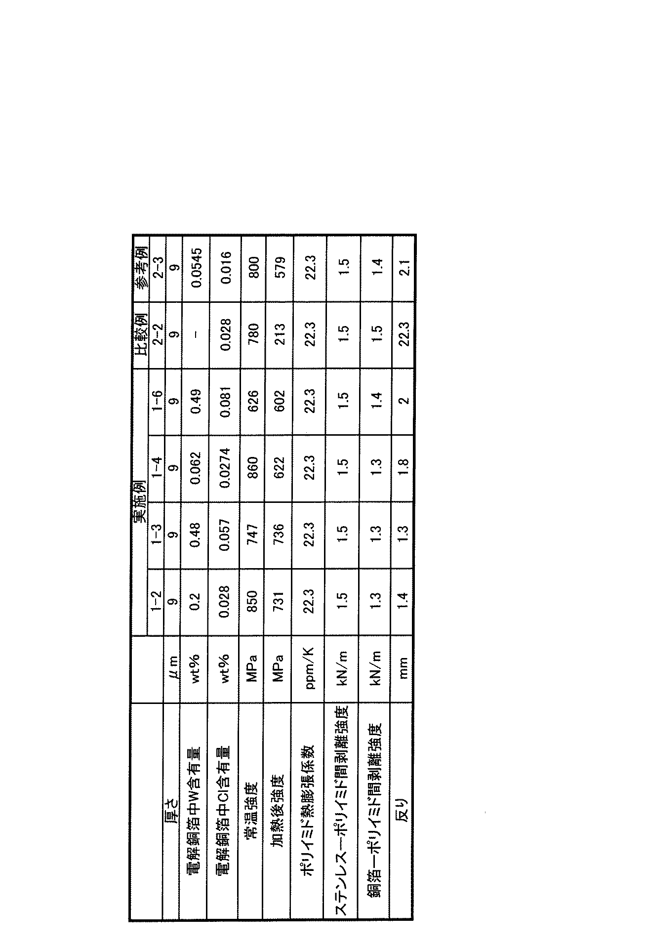
- Electrolytic Copper Foil As shown in Table 2, HDD suspension substrates were prepared using the electrolytic copper foils of Examples 1-2 to 4, 1-6, Comparative Example 2-2, and Reference Example 2-3.
- Synthesis example 2 In order to synthesize a polyimide resin having a glass transition temperature of 300 ° C. or less, 6.3 mol of DADMB was weighed and dissolved in 25.5 kg of the solvent DMAc while stirring in a 40 L planetary mixer. Next, 6.4 mol of BPDA was added, and stirring was continued at room temperature for 3 hours to conduct a polymerization reaction, whereby a viscous polyimide precursor B solution was obtained.
- the glass transition temperature by the dynamic viscoelasticity measuring apparatus after imidation of the polyimide precursor B by this synthesis example was 225 degreeC.
- DADMB 4,4′-diamino-2,2′-dimethylbiphenyl
- DMAc N, N-dimethylacetamide
- BPDA 3,3 ′
- BAPP 2,2′- Bis [4- (4-aminophenoxy) phenyl] propane
- An HDD suspension substrate was prepared.
- the polyimide precursor B solution obtained in Synthesis Example 2 is placed on a stainless steel foil (manufactured by Nippon Steel Co., Ltd., SUS304, tension annealed product, thickness 20 ⁇ m) so that the thickness after curing is 1 ⁇ m. And then dried at 110 ° C. for 3 minutes.
- the prepared electrolytic copper foils were superposed and thermocompression bonded using a vacuum press machine under conditions of a surface pressure of 15 Mpa, a temperature of 320 ° C., and a press time of 20 minutes, to obtain a target HDD suspension substrate.
- Adhesive force between metal foil and polyimide resin is to form a laminate of double-sided metal foil by thermocompression bonding of electrolytic copper foil after forming a polyimide resin layer on stainless steel foil, A test piece for measuring 1/8 inch wiring width was prepared by processing into a predetermined shape. This sample was attached to the fixed plate on the SUS foil side and the copper alloy foil or copper foil side, and each metal foil was peeled off in the 90 ° direction using a tensile tester, and the strength was measured.
- a laminate having a diameter of 65 mm was made by processing the laminate, and after standing for 24 hours at 23 ° C. and a humidity of 50%, the portion where the warpage was greatest when placed on a desk was measured with calipers.
- linear thermal expansion coefficient was measured by heating up to 255 ° C. at a rate of 20 ° C./minute using a thermomechanical analyzer (manufactured by Seiko Instruments Inc.) and holding at that temperature for 10 minutes. Further, cooling was performed at a constant rate of 5 ° C / min. The average thermal expansion coefficient (linear thermal expansion coefficient) from 240 ° C. to 100 ° C. during cooling was calculated.
- the results are shown in Table 2.
- the HDD suspension substrate having the configuration of the stainless steel foil / polyimide resin layer / electrolytic copper foil using the electrolytic copper foil of Examples and Reference Examples sufficiently satisfies the required characteristics as a suspension substrate material.
- the HDD suspension substrate using the electrolytic copper foil of the comparative example has a large warp as a suspension substrate material, and could not satisfy the required characteristics.
- an electrolytic copper foil that has a high mechanical strength in the normal state and is hardly thermally deteriorated even when heated at 300 ° C. or higher.
- an excellent electrolytic copper foil can be provided as a current collector for a lithium ion secondary battery, and an excellent secondary battery can be provided by using the current collector.
- the electrolytic copper foil of the present invention is suitable as a constituent material in the field of printed wiring board materials that require high mechanical strength even after heating, such as HDD suspension materials or TAB materials.
Landscapes
- Chemical & Material Sciences (AREA)
- Engineering & Computer Science (AREA)
- Materials Engineering (AREA)
- Chemical Kinetics & Catalysis (AREA)
- Electrochemistry (AREA)
- Metallurgy (AREA)
- Organic Chemistry (AREA)
- General Chemical & Material Sciences (AREA)
- Mechanical Engineering (AREA)
- Manufacturing & Machinery (AREA)
- Thermal Sciences (AREA)
- Crystallography & Structural Chemistry (AREA)
- Physics & Mathematics (AREA)
- Cell Electrode Carriers And Collectors (AREA)
Abstract
Description
本発明は、前記電解銅箔を二次電池用集電体とし、該集電体に活物質を堆積して二次電池用電極とし、該電極を組み込んだ二次電池に関するものできる。
本発明の電解銅箔は、該電解銅箔を導電材としたリジッドプリント配線板、フレキシブルプリント配線板、電磁波シールド材料等に好適に採用することができる。
a.FSA(フレックス サスペンション アッセンブリ)法と呼ばれるフレキシブルプリント基板を加工し接着剤を用いて張り合わせたタイプ
b.CIS(サーキット・インテグレーティッド・サスペンション)法と呼ばれるポリイミド樹脂の前駆体であるアミック酸を形状加工した後、イミド化し更にポリイミド上にメッキ加工を施すことにより配線を形成するタイプ
c.TSA(トレース・サスペンション・アッセンブリ)法と呼ばれるステンレス箔-ポリイミド樹脂-銅箔からなる積層体をエッチング加工により所定の形状に加工するタイプ
ラミネート後に積層体に反りを生じさせないためには、加熱時の寸法変化ができるだけ小さい銅合金箔の提供が求められている。
TAB製品においては、製品のほぼ中央部に位置するデバイスホールに配されるインナーリード(フライングリード)に対し、ICチップの複数の端子を直接ボンディングする。このボンディングはボンディング装置を用いて、瞬間的に通電加熱し、一定のボンディング圧を付加して行う。このとき、電解銅箔をエッチング形成して得られたインナーリードが、ボンディング圧で引っ張られて伸びるという問題がある。
さらには、電解銅箔の強度が低いと塑性変形してインナーリードにたるみが発生し、著しい場合には破断する可能性がある。
従って、インナーリードの線幅を細線化するには、使用する電解銅箔は低粗度化された粗面を持ち、かつ高強度であることが要求される。
負極の形成法としては、負極活物質とバインダー樹脂(活物質と銅箔基板とを結着することを目的に添加される)を溶剤に溶かしたスラリーを銅箔基板上に塗布し、バインダー樹脂の硬化温度以上の温度で乾燥させた後、プレスすることで形成する方法が一般的である。
近年、電池の高容量化に伴い着目されている、理論容量の高いケイ素、スズ、ゲルマニウム合金系材料などからなる活物質は、充放電時のリチウムの挿入脱離に伴う体積膨張率が非常に大きく、上述したバインダー樹脂では強度が足りない。そこで、銅基板との接着強度の高いポリイミド系樹脂が好ましく使用されてきている。しかし、ポリイミド系樹脂は上述したバインダー樹脂と違い、硬化温度が300℃程度と非常に高く、この加熱条件に耐え得る負極集電体(銅箔)が要求されている。
有機添加剤は通常は結晶の成長を抑制する効果のあるものが多く、結晶粒界に取り込まれると考えられている。
この場合、結晶粒界に取り込まれる有機添加剤の量が多いほど機械的強度が向上する傾向にある(非特許文献1:志賀章二;金属表面技術 Vol31, No10,p573 (1980))。
しかし圧延銅箔は電解銅箔に比べると高価であり、幅、厚さ等の要求を満足させることが難しい。
しかし、銅箔の耐熱性を改善できる金属を電解銅箔中に取り込むことは非常に困難であった。即ち、銅箔の耐熱性を改善する金属は銅箔中に非常に取り込み難い金属である。
また、本発明者等は、たとえば、HDDサスペンション材料、TAB材料として、或いはSi又はSn合金系活物質の大きな膨張、収縮を繰り返す活物質に対して、ポリイミドバインダーの使用を可能とし、集電体(銅箔)として変形しない電解銅箔の開発に成功した。
また、本発明はポリイミドフィルムと張り合わせるプリント配線板分野における用途において機械的強度に優れた電解銅箔を提供することを目的とする。
更に本発明は、Si又はSn合金系活物質を用いるリチウムイオン二次電池で、Si又はSn合金系活物質の大きな膨張、収縮に対して、集電体(銅箔)と活物質との密着性をポリイミドバインダーにより保持し、集電体(銅箔)が変形あるいは破断しない銅箔を提供することを目的とする。
より好ましくは、本発明電解銅箔のタングステン含有量は、0.06wt%~0.5wt%である。
本発明電解銅箔はタングステンを、0.06wt%~0.5wt%含有し、塩素を、0.001wt%~0.07wt%含有する。
好ましくは、前記タングステンの全てまたは一部が酸化物として取り込まれている。
前記電解銅箔に含まれるタングステンの量は0.06wt%以上であり、より好ましくは0.06wt%~0.5wt%の範囲である。
タングステンの含有量を0.06wt%以上とする理由は、含有量が0.06wt%以下の銅箔と比べて300℃×1時間の熱処理後に常温で測定した引張強度が向上し、電池用集電体として使用することで電池のサイクル寿命が長くなるためである。
タングステンの添加量は好ましくは、0.5wt%以下とする理由は、0.5wt%よりも多く添加してもその効果は飽和し、物性改善の効果が殆ど見られないためである。また、導電率の低下原因にもなり好ましくない。
しかし、電解液に塩素イオンを添加しても、液中にチオ尿素系化合物を添加すると製箔条件によってはタングステンが箔中に取り込まれる、との知見を得た。
塩素の含有量は0.001wt%以上とする理由は、含有量が0.001wt%以下では銅箔表面の表面平滑性が失われるためである。また、塩素の含有量を0.07wt%以下とする理由は、0.07wt%以上含有させると製箔した電解銅箔の初期強度が低下する傾向を示し、初期強度が低下することで加熱後の強度も低くなるためである。
Cu=70g/L
H2SO4=50g/L
電解条件:
電流密度=40A/dm2
液温=45℃
添加剤A:チオ尿素系化合物=2~20mg/L
添加剤B:タングステン塩(タングステンとして)=150~1,000mg/L
添加剤C:塩素イオン=5~70mg/L
なお、上記添加剤Bについては、「タングステン金属として150~1,000mg/Lに相当する量のタングステン塩」を意味する(以下同様)。
>N-C(=S)-N<
チオ尿素系化合物の例としては、チオ尿素、N,N-ジエチルチオ尿素、テトラメチルチオ尿素、エチレンチオ尿素である。しかし、これらは後述する実施例で使用したものを例示しているに過ぎず、以上で述べたような構造的特徴を有し、同様の効果を発揮する化合物であれば、いずれの化合物も使用可能である。
タングステンは酸性溶液中では酸化物として存在するが、塩素を含む電解液を用いた銅電析では銅の析出面上を塩素イオンが被覆しているため、タングステン酸化物は銅に吸着されず、箔中へのタングステンの取り込みが起こらない。該電解液にチオ尿素系化合物を添加すると、[=S]構造が塩素イオンよりも優先的に銅上に吸着して銅に有機分子の吸着層を形成する。該吸着層上にタングステン酸化物が吸着することにより、タングステンはチオ尿素系化合物と一緒に箔中に取り込まれるものと推考される。
従って、タングステンを含有する電解銅箔は300℃程度の高温で加熱しても、タングステン酸化物は結晶粒界にとどまり、銅の微細結晶が熱により再結晶し、結晶が粗大化するのを防ぐ働きをすると考えられる。
タングステンが添加されていない場合は、電解銅箔製箔用の電解液に添加されている金属元素は銅である。従って、硫酸銅と硫酸を含有する電解液中で銅-チオ尿素系化合物が形成される。この電解液による銅電析で電解銅箔を形成すると、銅-チオ尿素系化合物が結晶粒界に吸着され、結晶核の成長を抑制し、結晶粒を微細化し、常態で大きな機械的強度を備えた電解銅箔を形成する。
添加するチオ尿素系化合物の量を2mg/L~20mg/Lとするのは、2mg/L未満では銅箔中にタングステンを規定量取り込むことができず、300℃×1時間の熱処理後の引張強度が低下してしまい、20mg/Lを超えて添加すると箔の状態において反り(カ-ル)が強くなるため、添加量は2mg/L~20mg/Lが好ましい範囲である。
本発明のタングステン含有電解銅箔は上記二次電池用集電体が要求する諸特性を満足する。従ってかかる電解銅箔を集電体とし、該集電体にシリコン、ゲルマニウム、錫又はそれらの合金化合物またはそれらを主成分とする活物質を堆積して電極とし、該電極を組み込むことで性能の優れたリチウムイオン二次電池を製造することができる。
なお、本発明電解銅箔はリチウムイオン二次電池の集電体として特に優れているが、他の電池の電極用集電体としても好適に使用できることは勿論である。
表1に示す量の銅、硫酸、塩素イオン、タングステン、チオ尿素系有機添加剤を添加した硫酸銅と硫酸を含有する電解液を用いて貴金属酸化物被覆チタンを陽極に、チタン製回転ドラムを陰極として、下記電解条件で電解銅箔を製箔した。
電解条件
電流密度 40A/dm2
温度 45℃

このようにして製箔した電解銅箔に下記条件で防錆処理を施した。
製箔した電解銅箔(未処理銅合金箔)をCrO3;1g/L水溶液に5秒間浸漬して、クロメート処理を施し、水洗後乾燥させた。
なお、ここでは、クロメート処理を行ったが、ベンゾトリアゾール系処理、或いはシランカップリング剤処理、又はクロメート処理後にシランカップリング剤処理を行ってもよいことは勿論である。
表1に示す量の銅、硫酸、塩素、チオ尿素系有機添加剤を添加した硫酸銅と硫酸を含有する電解液を用いて貴金属酸化物被覆チタンを陽極に、チタン製回転ドラムを陰極として、下記電解条件で電解銅箔を製箔した。
電解条件
電流密度 40A/dm2
温度 45℃
このようにして製箔した銅箔に実施例と同様の表面処理を行った。
表1に示す量の銅、硫酸、塩素イオン、タングステン、チオ尿素系有機添加剤を添加した硫酸銅と硫酸を含有する電解液を用いて貴金属酸化物被覆チタンを陽極に、チタン製回転ドラムを陰極として、下記電解条件で電解銅箔を製箔した。
電解条件
電流密度 40A/dm2
温度 45℃
このようにして製箔した銅箔に実施例と同様の表面処理を行った。
銅箔中のタングステンの含有量の測定
タングステン含有量は、一定重量の電解銅箔を酸で溶解した後、溶液中のタングステンをICP発光分光分析法により求めた。
使用機器 :ICPS-7000(島津製作所)
銅箔の引張り強度の測定
銅箔の引張強度は、IPC-TM-650に基づいて箔の加熱前と加熱後に付き測定した。
使用機器 : AG-I (島津製作所)
塩素含有量の測定
塩素含有量は、一定重量の電解銅箔を酸で溶解した後、溶液中の塩素を硝酸銀滴定により定量を行い、算出を行った。
電解銅合金中に含有されるタングステンの化学結合状態や電子状態の解析をXAFS(X線微細吸収構造:X-ray Absorption Fine Structure)法で行った。XAFS法では、試料にX線エネルギーを変化させながらX線を照射し、得られたX線吸収スペクトルから試料中の化学結合状態や電子状態の解析を行う。
その他、X線吸収スペクトルを得る手法として、入射したX線の強度と透過したX線の強度からX線吸収スペクトルを求める透過法、X線の吸収に伴って試料から発せられる蛍光X線の強度を測定する蛍光法がある。
金属材料などの添加元素を分析対象とするとき、その添加量は微量であり透過法でのXAFSスペクトルを得ることは困難である。この様な場合に有効なのが上記に記した蛍光法である。蛍光法の特徴としては、その光軸系よりX線の照射面積が広く取れることにより微量成分の元素でもXAFS測定が可能であることである。
本測定では高強度銅箔中のタングステンの化学結合状態や電子状態を知ることが目的であり、タングステンの量は微量であり、透過法でXAFSスペクトルを得るには困難であることから蛍光法を選択した。
測定に関してはSPring-8の産業利用ビームラインBL14B2を使用した。測定したX線のエネルギー範囲は10000~10434eCとした。このエネルギー範囲にはタングステンのL3-吸収端(10207eV)があるため本測定の目的に適う。
次に実施例で製箔した電解銅箔を集電体として、リチウム二次電池を作成し、サイクル寿命試験を行った。
粉末状のSi合金系活物質(平均粒径0.1μm~10μm)を85、バインダー(ポリイミド)を15の比率(重量比)で混合し、N-メチルピロリドン(溶剤)に分散させて活物質スラリーとした。
次いで、このスラリーを、作成した12μm厚の電解銅箔両面に塗布し、乾燥後ローラープレス機で圧縮形成し、その後、窒素雰囲気下、300℃で1時間焼結し、負極とした。この負極は、成形後の負極合剤の膜厚が両面共に20μmと同一であった。
アルゴン雰囲気下のグローブボックス内で、以下の構成で評価用三極式セルを構築した。
負極:上記で作製のSi合金系負極
対極、参照極:リチウム箔
電解液:1mol/L LiPF6/EC+DEC(3:7vol%)
充電はLiの標準単極電位基準に対して0.02Vまで定電流で行い、その後はCVで(定電位のまま)電流が0.05Cまで低下した時点で充電終了とした。なお、Cは充放電レートを示す。放電は定電流にて0.1Cで1.5V(Li基準)まで行った。同じ0.1C相当電流で充放電を繰り返した。
サイクル寿命は、放電容量が1サイクル目の放電容量の70%に達するまでのサイクル数とした。また、充放電サイクルを行った後電池を分解し、箔の変形性の評価を行った。その結果を表1に示す。
また、タングステン含有量が0.06wt%~0.5wt%の範囲にある実施例は、その範囲外である参考例に比べて、サイクル特性が良好であった。
また、実施例1-6のタングステン含有量は実施例1-3と同程度であるが、塩素の含有量が0.07wt%を超えているため、初期の強度が実施例1-3及び比較例2-1,2-2よりも低下している。しかし、その後の加熱後の強度は比較例2-1、2-2に比べて高く、加熱による低下度合いが小さいことがわかる。
しかし、このように塩素の含有量が0.07wt%を超えると初期強度の低下が生じ、結果的に加熱後強度の値が低くなり、サイクル特性の低下を引き起こす要因となるため、塩素の含有量は0.07wt%以下であることが好ましい。
本実施例では、電解銅箔を作成した後、ステンレス箔/ポリイミド樹脂層/電解銅箔の構成であるHDDサスペンション用基板を作成し、その特性評価を行った。
電解銅箔の準備
表2に示すように実施例1-2~4、1-6、比較例2-2、参考例2-3の電解銅箔を用いてHDDサスペンション用基板を作成した。
合成例1
線膨張係数が30ppm/K以下の低熱膨張性のポリイミド系樹脂を合成するため、9.0モルのDADMBを秤量し、40Lのプラネタリーミキサーの中で攪拌しながら溶媒DMAc25.5kgに溶解させた。次いで、8.9モルのBPDAを加え、室温にて3時間攪拌を続けて重合反応を行い、粘稠なポリイミド前駆体Aの溶液を得た。本合成例によるポリイミド前駆体Aのイミド化後の線膨張係数は、13ppm/Kであった。
ガラス転移温度が300℃以下のポリイミド系樹脂を合成するため、6.3molのDADMBを秤量し、40Lのプラネタリーミキサーの中で攪拌しながら溶媒DMAc25.5kgに溶解させた。次いで、6.4molのBPDAを加え、室温にて3時間攪拌を続けて重合反応を行い、粘稠なポリイミド前駆体Bの溶液を得た。本合成例によるポリイミド前駆体Bのイミド化後の動的粘弾性測定装置によるガラス転移温度は、225℃であった。
DADMB:4,4’-ジアミノ-2,2’-ジメチルビフェニル
DMAc:N,N-ジメチルアセトアミド
BPDA:3,3’,4,4’-ビフェニルテトラカルボン酸二無水物BAPP:2,2’-ビス[4-(4-アミノフェノキシ)フェニル]プロパン
実施例1-2~4、1-6、比較例2-2、参考例2-3で準備した電解銅箔を用い、ステンレス箔/ポリイミド樹脂層/電解銅箔の構成であるHDDサスペンション用基板を作成した。
(a)合成例2で得られたポリイミド前駆体Bの溶液をステンレス箔(新日本製鐵株式会社製、SUS304、テンションアニール処理品、厚み20μm)上に、硬化後の厚みが1μmになるように塗布して110℃で3分乾燥し、(b)その後、その上に合成例1で得られたポリイミド前駆体Aの溶液を硬化後の厚さが7.5μmになるように塗布し、(c)110℃で10分乾燥し、(d)更にその上に合成例2で得られたポリイミド前駆体Bの溶液をそれぞれ硬化後の厚みが1.5μmになるように塗布し、(e)110℃で3分乾燥し(f)その後、更に130~360℃の範囲で数段階、各3分間段階的な熱処理によりイミド化を完了させ、(g)ステンレス上にポリイミド樹脂層の厚み10μmの積層体を得た。なお、第1層目のポリイミド樹脂層と第3層目のポリイミド樹脂層は同じとした。
次に、準備した電解銅箔を重ね合わせ、真空プレス機を用いて、面圧15Mpa、温度320℃、プレス時間20分の条件で加熱圧着して目的のHDDサスペンション用基板を得た。
金属箔とポリイミド系樹脂との間の接着力は、ステンレス箔上にポリイミド系樹脂層を形成した後、更に電解銅箔を熱圧着して両面金属箔の積層体を作成し、所定の形状に加工することにより1/8インチ配線幅の測定用試験片を作成した。このサンプルを固定板にSUS箔側及び銅合金箔または銅箔側をそれぞれ貼り付け、引張試験機を用いて、各金属箔を90°方向に引き剥がし強さを測定した。
積層体を加工して直径65mmのディスクを作成し、23℃、湿度50%で24時間放置後、机上に置いた際に最も反りが大きくなる部分をノギスにより測定した。
線熱膨張係数の測定は、サーモメカニカルアナライザー(セイコーインスツルメンツ(株)製)を用いて255℃まで20℃/分の速度で昇温し、その温度で10分間保持した後、更に5℃/分の一定速度で冷却した。冷却時の240℃から100℃までの平均熱膨張係数(線熱膨張係数)を算出した。
比較例の電解銅箔を用いたHDDサスペンション用基板はサスペンション基板材料としては反りが大きく、要求特性を満たすことができなかった。
また、本発明によれば、リチウムイオン二次電池用集電体として優れた電解銅箔を提供でき、該集電体を用いることで優れた二次電池を提供することができる。
Claims (10)
- タングステン(W)を、0.06wt%以上含有する電解銅箔。
- タングステン(W)を、0.06wt%~0.5wt%含有する電解銅箔。
- タングステンを含有し、残部が実質的に銅からなる電解銅箔。
- タングステン(W)を、0.06wt%~0.5wt%含有し、塩素(Cl)を0.001wt%~0.07wt%含有する電解銅箔。
- 前記タングステンの全てまたは一部が酸化物である請求項1~4のいずれかに記載の電解銅箔。
- タングステンを0.06wt%~0.5wt%含み、300℃×1時間の熱処理後に常温で測定した引張強度が500MPa以上である電解銅箔。
- タングステンを0.06wt%~0.5wt%含み、塩素(Cl)を、0.001wt%~0.07wt%含み、300℃×1時間の熱処理後に常温で測定した引張強度が500MPa以上である電解銅箔。
- 請求項1~7のいずれかに記載の電解銅箔を用いた二次電池用集電体。
- 請求項1~7のいずれかに記載の電解銅箔を集電体として用い、その表面に活物質が堆積されている二次電池用電極。
- 請求項1~7のいずれかに記載の電解銅箔を集電体として用いた二次電池。
Priority Applications (3)
| Application Number | Priority Date | Filing Date | Title |
|---|---|---|---|
| CN201480002113.3A CN104540981B (zh) | 2013-01-29 | 2014-01-28 | 电解铜箔、使用该电解铜箔的电池用集电体、使用该集电体的二次电池用电极、以及使用该电极的二次电池 |
| KR1020157003661A KR101787513B1 (ko) | 2013-01-29 | 2014-01-28 | 전해 동박, 상기 전해 동박을 이용한 전지용 집전체, 상기 집전체를 이용한 이차전지용 전극, 상기 전극을 이용한 이차전지 |
| JP2014519741A JP5579350B1 (ja) | 2013-01-29 | 2014-01-28 | 電解銅箔、該電解銅箔を用いた電池用集電体、該集電体を用いた二次電池用電極、該電極を用いた二次電池 |
Applications Claiming Priority (2)
| Application Number | Priority Date | Filing Date | Title |
|---|---|---|---|
| JP2013014303 | 2013-01-29 | ||
| JP2013-014303 | 2013-01-29 |
Publications (1)
| Publication Number | Publication Date |
|---|---|
| WO2014119583A1 true WO2014119583A1 (ja) | 2014-08-07 |
Family
ID=51262296
Family Applications (1)
| Application Number | Title | Priority Date | Filing Date |
|---|---|---|---|
| PCT/JP2014/051861 Ceased WO2014119583A1 (ja) | 2013-01-29 | 2014-01-28 | 電解銅箔、該電解銅箔を用いた電池用集電体、該集電体を用いた二次電池用電極、該電極を用いた二次電池 |
Country Status (5)
| Country | Link |
|---|---|
| JP (1) | JP5579350B1 (ja) |
| KR (1) | KR101787513B1 (ja) |
| CN (1) | CN104540981B (ja) |
| TW (1) | TWI602953B (ja) |
| WO (1) | WO2014119583A1 (ja) |
Cited By (5)
| Publication number | Priority date | Publication date | Assignee | Title |
|---|---|---|---|---|
| CN110504453A (zh) * | 2018-05-16 | 2019-11-26 | 日进材料股份有限公司 | 电解铜箔和使用电解铜箔的二次电池 |
| EP3540836A4 (en) * | 2016-11-11 | 2020-05-13 | Iljin Materials Co., Ltd. | Electrolytic copper foil for secondary battery, having excellent flexural resistance, and method for producing same |
| EP3540833A4 (en) * | 2016-11-11 | 2020-05-13 | Iljin Materials Co., Ltd. | ELECTROLYTIC COPPER FILM FOR SECONDARY BATTERY AND METHOD FOR PRODUCING THE SAME |
| EP3540834A4 (en) * | 2016-11-11 | 2020-05-20 | Iljin Materials Co., Ltd. | ELECTROLYTIC COPPER FILM FOR A SECONDARY BATTERY WITH EXCELLENT PHYSICAL PROPERTIES AT LOW TEMPERATURES AND METHOD FOR THE PRODUCTION THEREOF |
| JP2020163408A (ja) * | 2019-03-28 | 2020-10-08 | Jx金属株式会社 | 金属製品及びその製造方法 |
Families Citing this family (1)
| Publication number | Priority date | Publication date | Assignee | Title |
|---|---|---|---|---|
| WO2017051767A1 (ja) * | 2015-09-25 | 2017-03-30 | 古河電気工業株式会社 | 電解銅箔、その電解銅箔を用いた各種製品 |
Citations (4)
| Publication number | Priority date | Publication date | Assignee | Title |
|---|---|---|---|---|
| JPH0967693A (ja) * | 1995-08-29 | 1997-03-11 | Nikko Gould Foil Kk | 電解銅箔の製造方法 |
| JP3238278B2 (ja) * | 1994-04-12 | 2001-12-10 | 株式会社日鉱マテリアルズ | 電解銅箔の製造方法 |
| WO2013018773A1 (ja) * | 2011-07-29 | 2013-02-07 | 古河電気工業株式会社 | 電解銅合金箔、その製造方法、それの製造に用いる電解液、それを用いた二次電池用負極集電体、二次電池及びその電極 |
| WO2013065699A1 (ja) * | 2011-10-31 | 2013-05-10 | 古河電気工業株式会社 | 高強度、高耐熱電解銅箔及びその製造方法 |
Family Cites Families (4)
| Publication number | Priority date | Publication date | Assignee | Title |
|---|---|---|---|---|
| JP2717911B2 (ja) * | 1992-11-19 | 1998-02-25 | 日鉱グールド・フォイル株式会社 | 印刷回路用銅箔及びその製造方法 |
| KR100553840B1 (ko) * | 2003-05-29 | 2006-02-24 | 일진소재산업주식회사 | 인쇄회로기판용 동박의 제조 방법 |
| JP4859238B2 (ja) * | 2007-03-30 | 2012-01-25 | Jx日鉱日石金属株式会社 | 高強度高導電性耐熱銅合金箔 |
| JP5128695B2 (ja) * | 2010-06-28 | 2013-01-23 | 古河電気工業株式会社 | 電解銅箔、リチウムイオン二次電池用電解銅箔、該電解銅箔を用いたリチウムイオン二次電池用電極、該電極を使用したリチウムイオン二次電池 |
-
2014
- 2014-01-28 WO PCT/JP2014/051861 patent/WO2014119583A1/ja not_active Ceased
- 2014-01-28 KR KR1020157003661A patent/KR101787513B1/ko active Active
- 2014-01-28 JP JP2014519741A patent/JP5579350B1/ja active Active
- 2014-01-28 CN CN201480002113.3A patent/CN104540981B/zh active Active
- 2014-01-29 TW TW103103448A patent/TWI602953B/zh active
Patent Citations (4)
| Publication number | Priority date | Publication date | Assignee | Title |
|---|---|---|---|---|
| JP3238278B2 (ja) * | 1994-04-12 | 2001-12-10 | 株式会社日鉱マテリアルズ | 電解銅箔の製造方法 |
| JPH0967693A (ja) * | 1995-08-29 | 1997-03-11 | Nikko Gould Foil Kk | 電解銅箔の製造方法 |
| WO2013018773A1 (ja) * | 2011-07-29 | 2013-02-07 | 古河電気工業株式会社 | 電解銅合金箔、その製造方法、それの製造に用いる電解液、それを用いた二次電池用負極集電体、二次電池及びその電極 |
| WO2013065699A1 (ja) * | 2011-10-31 | 2013-05-10 | 古河電気工業株式会社 | 高強度、高耐熱電解銅箔及びその製造方法 |
Cited By (6)
| Publication number | Priority date | Publication date | Assignee | Title |
|---|---|---|---|---|
| EP3540836A4 (en) * | 2016-11-11 | 2020-05-13 | Iljin Materials Co., Ltd. | Electrolytic copper foil for secondary battery, having excellent flexural resistance, and method for producing same |
| EP3540833A4 (en) * | 2016-11-11 | 2020-05-13 | Iljin Materials Co., Ltd. | ELECTROLYTIC COPPER FILM FOR SECONDARY BATTERY AND METHOD FOR PRODUCING THE SAME |
| EP3540834A4 (en) * | 2016-11-11 | 2020-05-20 | Iljin Materials Co., Ltd. | ELECTROLYTIC COPPER FILM FOR A SECONDARY BATTERY WITH EXCELLENT PHYSICAL PROPERTIES AT LOW TEMPERATURES AND METHOD FOR THE PRODUCTION THEREOF |
| US20210230760A1 (en) * | 2016-11-11 | 2021-07-29 | Iljin Materials Co., Ltd. | Electrolytic copper foil for secondary battery, having enhanced physical properties at low temperature, and method for producing same |
| CN110504453A (zh) * | 2018-05-16 | 2019-11-26 | 日进材料股份有限公司 | 电解铜箔和使用电解铜箔的二次电池 |
| JP2020163408A (ja) * | 2019-03-28 | 2020-10-08 | Jx金属株式会社 | 金属製品及びその製造方法 |
Also Published As
| Publication number | Publication date |
|---|---|
| TWI602953B (zh) | 2017-10-21 |
| KR101787513B1 (ko) | 2017-10-18 |
| TW201443290A (zh) | 2014-11-16 |
| KR20150070088A (ko) | 2015-06-24 |
| JP5579350B1 (ja) | 2014-08-27 |
| JPWO2014119583A1 (ja) | 2017-01-26 |
| CN104540981A (zh) | 2015-04-22 |
| CN104540981B (zh) | 2016-09-14 |
Similar Documents
| Publication | Publication Date | Title |
|---|---|---|
| CN103348041B (zh) | 电解铜合金箔、其制备方法、制备中所用的电解液、使用该电解铜合金箔的二次电池用负极集电体、二次电池及其电极 | |
| JP5916904B1 (ja) | 電解銅箔、リチウムイオン二次電池用負極電極及びリチウムイオン二次電池並びにリジッドプリント配線板及びフレキシブルプリント配線板 | |
| JP5740055B2 (ja) | 電解銅箔、該電解銅箔を用いたリチウムイオン二次電池用電極、該電極を用いたリチウムイオン二次電池 | |
| JP5579350B1 (ja) | 電解銅箔、該電解銅箔を用いた電池用集電体、該集電体を用いた二次電池用電極、該電極を用いた二次電池 | |
| US9428840B2 (en) | High strength, high heat resistance electrodeposited copper foil and manufacturing method for same | |
| WO2012070589A1 (ja) | 表面処理銅箔 | |
| JP5706045B2 (ja) | 電解銅箔とその製造方法 | |
| TWI514937B (zh) | 佈線電路基板 | |
| JP6582156B1 (ja) | 電解銅箔、並びに該電解銅箔を用いたリチウムイオン二次電池用負極、リチウムイオン二次電池、銅張積層板及びプリント配線板 | |
| JP5697051B2 (ja) | 電解銅合金箔、その製造方法、その製造に用いる電解液、二次電池用負極集電体、二次電池及びその電極 | |
| JPWO2014119355A1 (ja) | 電解銅箔及びその製造方法 | |
| JP2022050471A (ja) | 耐屈曲性に優れた二次電池用電解銅箔及びその製造方法 | |
| JP2014101581A (ja) | 電解銅合金箔、その製造方法、その製造に用いる電解液、二次電池用負極集電体、二次電池及びその電極 | |
| KR102928314B1 (ko) | 표면 처리 동박, 동 클래드 적층판 및 프린트 배선판 |
Legal Events
| Date | Code | Title | Description |
|---|---|---|---|
| ENP | Entry into the national phase |
Ref document number: 2014519741 Country of ref document: JP Kind code of ref document: A |
|
| 121 | Ep: the epo has been informed by wipo that ep was designated in this application |
Ref document number: 14745936 Country of ref document: EP Kind code of ref document: A1 |
|
| ENP | Entry into the national phase |
Ref document number: 20157003661 Country of ref document: KR Kind code of ref document: A |
|
| NENP | Non-entry into the national phase |
Ref country code: DE |
|
| 122 | Ep: pct application non-entry in european phase |
Ref document number: 14745936 Country of ref document: EP Kind code of ref document: A1 |