WO2014119189A1 - 被覆アーク溶接棒 - Google Patents
被覆アーク溶接棒 Download PDFInfo
- Publication number
- WO2014119189A1 WO2014119189A1 PCT/JP2013/084621 JP2013084621W WO2014119189A1 WO 2014119189 A1 WO2014119189 A1 WO 2014119189A1 JP 2013084621 W JP2013084621 W JP 2013084621W WO 2014119189 A1 WO2014119189 A1 WO 2014119189A1
- Authority
- WO
- WIPO (PCT)
- Prior art keywords
- mass
- amount
- coated electrode
- arc welding
- welding rod
- Prior art date
Links
Images


Classifications
-
- B—PERFORMING OPERATIONS; TRANSPORTING
- B23—MACHINE TOOLS; METAL-WORKING NOT OTHERWISE PROVIDED FOR
- B23K—SOLDERING OR UNSOLDERING; WELDING; CLADDING OR PLATING BY SOLDERING OR WELDING; CUTTING BY APPLYING HEAT LOCALLY, e.g. FLAME CUTTING; WORKING BY LASER BEAM
- B23K35/00—Rods, electrodes, materials, or media, for use in soldering, welding, or cutting
- B23K35/22—Rods, electrodes, materials, or media, for use in soldering, welding, or cutting characterised by the composition or nature of the material
- B23K35/24—Selection of soldering or welding materials proper
- B23K35/30—Selection of soldering or welding materials proper with the principal constituent melting at less than 1550 degrees C
-
- B—PERFORMING OPERATIONS; TRANSPORTING
- B23—MACHINE TOOLS; METAL-WORKING NOT OTHERWISE PROVIDED FOR
- B23K—SOLDERING OR UNSOLDERING; WELDING; CLADDING OR PLATING BY SOLDERING OR WELDING; CUTTING BY APPLYING HEAT LOCALLY, e.g. FLAME CUTTING; WORKING BY LASER BEAM
- B23K35/00—Rods, electrodes, materials, or media, for use in soldering, welding, or cutting
- B23K35/22—Rods, electrodes, materials, or media, for use in soldering, welding, or cutting characterised by the composition or nature of the material
- B23K35/36—Selection of non-metallic compositions, e.g. coatings, fluxes; Selection of soldering or welding materials, conjoint with selection of non-metallic compositions, both selections being of interest
- B23K35/365—Selection of non-metallic compositions of coating materials either alone or conjoint with selection of soldering or welding materials
-
- B—PERFORMING OPERATIONS; TRANSPORTING
- B23—MACHINE TOOLS; METAL-WORKING NOT OTHERWISE PROVIDED FOR
- B23K—SOLDERING OR UNSOLDERING; WELDING; CLADDING OR PLATING BY SOLDERING OR WELDING; CUTTING BY APPLYING HEAT LOCALLY, e.g. FLAME CUTTING; WORKING BY LASER BEAM
- B23K35/00—Rods, electrodes, materials, or media, for use in soldering, welding, or cutting
- B23K35/22—Rods, electrodes, materials, or media, for use in soldering, welding, or cutting characterised by the composition or nature of the material
- B23K35/24—Selection of soldering or welding materials proper
- B23K35/30—Selection of soldering or welding materials proper with the principal constituent melting at less than 1550 degrees C
- B23K35/3053—Fe as the principal constituent
-
- B—PERFORMING OPERATIONS; TRANSPORTING
- B23—MACHINE TOOLS; METAL-WORKING NOT OTHERWISE PROVIDED FOR
- B23K—SOLDERING OR UNSOLDERING; WELDING; CLADDING OR PLATING BY SOLDERING OR WELDING; CUTTING BY APPLYING HEAT LOCALLY, e.g. FLAME CUTTING; WORKING BY LASER BEAM
- B23K35/00—Rods, electrodes, materials, or media, for use in soldering, welding, or cutting
- B23K35/22—Rods, electrodes, materials, or media, for use in soldering, welding, or cutting characterised by the composition or nature of the material
- B23K35/36—Selection of non-metallic compositions, e.g. coatings, fluxes; Selection of soldering or welding materials, conjoint with selection of non-metallic compositions, both selections being of interest
- B23K35/3601—Selection of non-metallic compositions, e.g. coatings, fluxes; Selection of soldering or welding materials, conjoint with selection of non-metallic compositions, both selections being of interest with inorganic compounds as principal constituents
- B23K35/3602—Carbonates, basic oxides or hydroxides
-
- B—PERFORMING OPERATIONS; TRANSPORTING
- B23—MACHINE TOOLS; METAL-WORKING NOT OTHERWISE PROVIDED FOR
- B23K—SOLDERING OR UNSOLDERING; WELDING; CLADDING OR PLATING BY SOLDERING OR WELDING; CUTTING BY APPLYING HEAT LOCALLY, e.g. FLAME CUTTING; WORKING BY LASER BEAM
- B23K35/00—Rods, electrodes, materials, or media, for use in soldering, welding, or cutting
- B23K35/40—Making wire or rods for soldering or welding
- B23K35/404—Coated rods; Coated electrodes
-
- C—CHEMISTRY; METALLURGY
- C22—METALLURGY; FERROUS OR NON-FERROUS ALLOYS; TREATMENT OF ALLOYS OR NON-FERROUS METALS
- C22C—ALLOYS
- C22C38/00—Ferrous alloys, e.g. steel alloys
- C22C38/002—Ferrous alloys, e.g. steel alloys containing In, Mg, or other elements not provided for in one single group C22C38/001 - C22C38/60
-
- C—CHEMISTRY; METALLURGY
- C22—METALLURGY; FERROUS OR NON-FERROUS ALLOYS; TREATMENT OF ALLOYS OR NON-FERROUS METALS
- C22C—ALLOYS
- C22C38/00—Ferrous alloys, e.g. steel alloys
- C22C38/02—Ferrous alloys, e.g. steel alloys containing silicon
-
- C—CHEMISTRY; METALLURGY
- C22—METALLURGY; FERROUS OR NON-FERROUS ALLOYS; TREATMENT OF ALLOYS OR NON-FERROUS METALS
- C22C—ALLOYS
- C22C38/00—Ferrous alloys, e.g. steel alloys
- C22C38/04—Ferrous alloys, e.g. steel alloys containing manganese
-
- C—CHEMISTRY; METALLURGY
- C22—METALLURGY; FERROUS OR NON-FERROUS ALLOYS; TREATMENT OF ALLOYS OR NON-FERROUS METALS
- C22C—ALLOYS
- C22C38/00—Ferrous alloys, e.g. steel alloys
- C22C38/18—Ferrous alloys, e.g. steel alloys containing chromium
- C22C38/22—Ferrous alloys, e.g. steel alloys containing chromium with molybdenum or tungsten
-
- C—CHEMISTRY; METALLURGY
- C22—METALLURGY; FERROUS OR NON-FERROUS ALLOYS; TREATMENT OF ALLOYS OR NON-FERROUS METALS
- C22C—ALLOYS
- C22C38/00—Ferrous alloys, e.g. steel alloys
- C22C38/18—Ferrous alloys, e.g. steel alloys containing chromium
- C22C38/24—Ferrous alloys, e.g. steel alloys containing chromium with vanadium
-
- C—CHEMISTRY; METALLURGY
- C22—METALLURGY; FERROUS OR NON-FERROUS ALLOYS; TREATMENT OF ALLOYS OR NON-FERROUS METALS
- C22C—ALLOYS
- C22C38/00—Ferrous alloys, e.g. steel alloys
- C22C38/18—Ferrous alloys, e.g. steel alloys containing chromium
- C22C38/26—Ferrous alloys, e.g. steel alloys containing chromium with niobium or tantalum
-
- C—CHEMISTRY; METALLURGY
- C22—METALLURGY; FERROUS OR NON-FERROUS ALLOYS; TREATMENT OF ALLOYS OR NON-FERROUS METALS
- C22C—ALLOYS
- C22C38/00—Ferrous alloys, e.g. steel alloys
- C22C38/18—Ferrous alloys, e.g. steel alloys containing chromium
- C22C38/32—Ferrous alloys, e.g. steel alloys containing chromium with boron
-
- B—PERFORMING OPERATIONS; TRANSPORTING
- B23—MACHINE TOOLS; METAL-WORKING NOT OTHERWISE PROVIDED FOR
- B23K—SOLDERING OR UNSOLDERING; WELDING; CLADDING OR PLATING BY SOLDERING OR WELDING; CUTTING BY APPLYING HEAT LOCALLY, e.g. FLAME CUTTING; WORKING BY LASER BEAM
- B23K2101/00—Articles made by soldering, welding or cutting
- B23K2101/04—Tubular or hollow articles
- B23K2101/12—Vessels
Definitions
- the present invention relates to a coated arc welding rod used for welding 2.25Cr-1Mo-V steel used in a pressure vessel in an energy plant such as an oil refining reactor.
- 2.25Cr-1Mo steel has been used for pressure vessels such as oil refining reactors.
- a higher strength 2.25Cr-1Mo-V steel reactor is being applied as a steel material that can withstand the design temperature, the high pressure and the high pressure.
- a coated arc welding rod or weld metal used for welding 2.25Cr-1Mo-V steel for petroleum refining reactors the development of a coated arc welding rod or weld metal with excellent creep rupture performance and toughness is proceeding. It has been.
- Patent Document 1 in a weld metal formed by coated arc welding, V: 0.20 to 0.70 mass% with respect to Cr: 2.00 to 3.25 mass%, and Nb, Co, W The creep strength is ensured by the addition of.
- Patent Document 2 V: 0.1 to 1.0% by mass and Nb: 0.02 to 0.50% with respect to Cr: 1.00 to 3.50% by mass with respect to the total mass of the welding rod. %, And the addition of Co, W, and Ni ensures creep strength and toughness.
- Patent Document 3 V: 0.01 to 0.60% by mass, W: 0.6 to 2.5% by mass with respect to Cr: 1.00 to 3.50% by mass with respect to the total mass of the welding rod. %, And the addition of Nb and Ta ensures the creep strength.
- JP-A-10-137975 JP 2002-263883 A Japanese Patent Laid-Open No. 2001-300768
- welding materials used for welding steel for petroleum refining reactors have excellent creep performance and follow-up properties such as toughness, temper embrittlement characteristics, and SR cracking resistance (intergranular cracking during stress relief annealing) That is compatible with welding workability.
- SR cracking resistance intergranular cracking during stress relief annealing
- the post-weld heat treatment (PWHT) conditions are 700 ° C. ⁇ 26 h, low temperature and short time, and the creep test conditions are 538 ° C./207 MPa, low temperature / low stress.
- PWHT post-weld heat treatment
- the creep test conditions are 538 ° C./207 MPa, low temperature / low stress.
- the PWHT condition is 740 ° C. ⁇ 1 h and the holding temperature is high, the holding time is short, and the creep test condition is 600 ° C./140 MPa
- both test conditions comply with the current market demand.
- the PWHT condition is 690 ° C. ⁇ 1 h
- the holding temperature is low
- the holding time is short
- the creep test condition is 600 ° C./140 MPa
- the present invention has been made in view of such a problem, and is a coating that achieves both excellent creep performance and toughness, temper embrittlement characteristics, SR crack resistance, and welding workability, which are performances following the creep performance. It is an object to provide an arc welding rod.
- the present inventors have found the following matters.
- the present inventors have provided a means for improving the creep performance when forming a 2.25Cr-1Mo-V steel weld metal having excellent creep strength and excellent toughness, temper embrittlement characteristics, and SR crack resistance.
- the idea of (1) carbide precipitation control and (2) microstructure control was obtained.
- the microstructure of the 2.25Cr-1Mo-V steel and its deposited metal is mainly bainite, and its creep deformation behavior is mainly due to the creep diffusion of dislocations and the old ⁇ grain boundaries and bainite block / packet / laser boundaries in the grains.
- the sliding is considered to be dominant.
- it is effective to disperse and precipitate fine carbides in the crystal grains that inhibit the creep diffusion of dislocations.
- it is effective to disperse and precipitate carbides that inhibit slip at the former ⁇ grain boundary, and to reduce slip sites, that is, to make the microstructure coarse.
- the total amount of metal carbonate in the coating agent is 5 to 10% by mass in terms of CO 2 and the alkali metal oxide in terms of alkali metal in terms of the total mass of the coated arc welding rod. 4 to 2.0% by mass, fluorine compound containing 1.0 to 5.0% by mass in terms of F, and the total of either or both of the core wire and the coating agent of the coated arc welding rod, C: 0.04 to 0.15% by mass, Si: 1.0 to 1.5% by mass, Mn: 0.7 to 1.2% by mass, Cr: 1.3 to 1.9% by mass %, Mo: 0.5 to 1.0 mass%, V: 0.3 to 0.5 mass%, Nb: 0.02 to 0.06 mass%, B: 0.005 to 0.015 mass%, Mg: 0.05-0.15 mass%, Fe: 60-75 mass%, Cu, Ni, Ti, Al, T as inevitable impurities
- the sum of a, Co, and W is 0.10% by mass or less, and the sum of S
- the coated arc welding rod contains a predetermined amount of metal carbonate in the coating agent, so that the weld bead is protected, the hydrogen partial pressure in the arc atmosphere is lowered, and the diffusion in the deposited metal is reduced.
- the amount of reactive hydrogen is reduced.
- operativity is provided to a covering arc welding rod by containing a predetermined amount of an alkali metal oxide in a coating agent. Further, by containing a predetermined amount of the fluorine compound in the coating agent, the fluorine compound acts as a slag forming agent without deteriorating the bead shape.
- the coated arc welding rod contains a predetermined amount of a predetermined component in one or both of the core wire and the coating material of the coated arc welding rod, so that the creep rupture performance, toughness, and temper embrittlement characteristics of the weld metal. SR cracking resistance and welding workability are improved.
- the welding workability is based on the viewpoints of arc stability, spatter generation amount, slag peelability, bead conformability, bead appearance, and the like.
- the coated arc welding rod according to the present invention is a total of either one or both of the core wire and the coating agent of the coated arc welding rod, and C: 0.05 to 0.10% by mass, based on the total mass of the coated arc welding rod, Si: 1.0 to 1.3% by mass, Mn: 0.8 to 1.2% by mass, Cr: 1.3 to 1.9% by mass, Mo: 0.5 to 1.0% by mass, V: 0.3 to 0.5 mass%, Nb: 0.02 to 0.06 mass%, B: 0.005 to 0.015 mass%, Mg: 0.05 to 0.10 mass%, Fe: 60 to Inclusive of 75% by mass, as the inevitable impurities, the total of Cu, Ni, Ti, Al, Ta, Co, and W is 0.10% by mass or less, and the total of S, Sn, As, Sb, Pb, and Bi is 0.00. It is preferable that it is 10 mass% or less.
- the creep rupture performance, toughness, temper embrittlement characteristics of the weld metal, SR cracking resistance and welding workability can be improved more easily.
- the coated arc welding rod according to the present invention a weld metal having excellent creep rupture performance, toughness, temper embrittlement characteristics, and SR cracking resistance can be obtained. Moreover, according to the covering arc welding rod which concerns on this invention, it is excellent in welding workability
- the total amount of metal carbonate in the coating agent is 5 to 10% by mass in terms of CO 2 and the alkali metal oxide is 0.4 in terms of alkali metal in terms of the total mass of the coated arc welding rod. -2.0 mass%, and fluorine compound is contained in an amount of 1.0-5.0 mass% in terms of F.
- the coated arc welding rod has a total of either one or both of the core wire and the coating material of the coated arc welding rod, and the total mass of the coated arc welding rod is C, Si, Mn, Cr, Mo, V, Nb, Contains a predetermined amount of B, Mg, Fe, and as an inevitable impurity, the sum of Cu, Ni, Ti, Al, Ta, Co, and W is less than a predetermined amount, and the sum of S, Sn, As, Sb, Pb, and Bi The predetermined amount or less.
- the total mass of the coated arc welding rod is C, Si, Mn, Cr, Mo, V, Nb, Contains a predetermined amount of B, Mg, Fe, and as an inevitable impurity, the sum of Cu, Ni, Ti, Al, Ta, Co, and W is less than a predetermined amount, and the sum of S, Sn, As, Sb, Pb, and Bi The predetermined amount or less.
- Coating arc welding rod contains metal carbonate, alkali metal oxide, and fluorine compound in the coating agent
- Metal carbonate decomposes into metal oxide and CO 2 by arc heat.
- the former forms a slag to protect the weld bead, and the latter is added to the coating material in order to lower the hydrogen partial pressure in the arc atmosphere and reduce the amount of diffusible hydrogen in the deposited metal.
- the metal carbonate or MgCO 3, etc. CaCO 3, BaCO 3, Na 2 CO 3, and is not particularly limited. However, if the content is too small, not only the slag generation amount is insufficient and the bead appearance is deteriorated, but also the amount of diffusible hydrogen in the deposited metal is increased and the cold cracking sensitivity is increased.
- Alkali metal oxide 0.4 to 2.0 mass% in terms of alkali metal>
- the alkali metal oxide serves as a binder for forming a coating, and is contained in water glass added to the coating agent in order to fix the coating to the core wire.
- Examples of the chemical composition include Na 2 O, K 2 O, Li 2 O, and the like, but these alkali metal oxides also affect the welding workability of the coated arc welding rod. If these alkali metal oxides are too little or too much, that is, if the amount of water glass added is too little or too much, welding workability, particularly arc stability is adversely affected. Therefore, the content per total mass of the coated arc welding rod is set to 0.4 to 2.0% by mass in terms of alkali metal.
- ⁇ Fluorine compound 1.0 to 5.0% by mass in terms of F>
- the fluorine compound is added to the coating agent as a slag forming agent.
- This fluorine compound is not only a metal fluoride represented by BaF 2 , CaF 2 , KF, NaF, AlF 3 , but also a composite metal fluoride represented by K 2 SiF 6 or PTFE, a high molecular polymer, etc. It is not particularly limited. However, if the content is too small or too large, the bead shape is deteriorated. Therefore, the content per total mass of the coated arc welding rod is 1.0 to 5.0 mass% in terms of F.
- a predetermined amount of a predetermined element is included in the total mass of either one or both of the core wire of the coated arc welding rod and the coating material and the total mass of the coated arc welding rod]
- C has a great influence on the hardenability of the weld metal and the precipitation form of carbides.
- the bainite transformation temperature becomes high, so that the bainite structure becomes coarse and the toughness and temper embrittlement characteristics are lowered.
- the amount of carbide precipitation becomes insufficient, and the creep rupture strength also decreases.
- the amount of C is excessively high, the amount of precipitated carbide increases and the creep strength increases, while the coarsening of the precipitated carbide is promoted, and the toughness and temper embrittlement characteristics decrease, Increases cracking susceptibility such as hot cracking, cold cracking, and SR cracking.
- arc stability deteriorates. Therefore, the C amount per the total mass of the coated arc welding rod is set to 0.04 to 0.15 mass%.
- the lower limit is 0.05 and the upper limit is 0.10% by mass.
- Si 1.0 to 1.5% by mass> Si has the effect of ensuring the room temperature strength of the weld metal and improving the toughness by deoxidizing and cleaning the weld metal.
- the amount of Si in the weld metal is too low, the creep strength is lowered, and further, the amount of oxygen in the weld metal is increased to form a coarse oxide, so that the toughness is lowered.
- bead conformability and bead appearance deteriorate.
- excessive addition of Si deteriorates the temper embrittlement characteristics. Therefore, the amount of Si per the total mass of the coated arc welding rod is 1.0 to 1.5 mass%.
- the lower limit is 1.0 mass% and the upper limit is 1.3 mass%.
- Mn is an element that lowers the bainite transformation temperature of the deposited metal after C
- the addition of Mn can lower the bainite transformation point to form a microstructure and improve toughness.
- Mn is an element that lowers the bainite transformation temperature of the deposited metal after C
- the addition of Mn can lower the bainite transformation point to form a microstructure and improve toughness.
- the increase in slip sites accompanying the refinement of the microstructure causes a decrease in the creep strength.
- Mn like Si, deoxidizes and cleans the weld metal to improve its toughness, while excessive addition reduces the temper embrittlement characteristics. Therefore, from the viewpoint of achieving both the toughness and temper embrittlement characteristics of the weld metal and the creep rupture strength, the Mn amount per total mass of the coated arc welding rod is set to 0.7 to 1.2% by mass.
- the lower limit is 0.8 mass% and the upper limit is 1.2 mass%.
- ⁇ Cr 1.3 to 1.9% by mass> Cr, together with Mo and V, is a basic component of high-strength 2.25Cr-1Mo-V steel.
- Cr is an indispensable component for forming carbides preferentially at the prior ⁇ grain boundaries to improve room temperature strength and creep strength, and to improve corrosion resistance. According to studies by the present inventors, it is clear that a decrease in Cr promotes the precipitation of fine carbides, and an increase in Cr promotes the precipitation of coarse carbides. If the amount of Cr in the weld metal is too small, fine carbides are excessively precipitated and the toughness is lowered, and the SR crack resistance is also deteriorated.
- the Cr amount per the total mass of the coated arc welding rod is set to 1.3 to 1.9% by mass.
- Mo is a basic component of high strength 2.25Cr-1Mo-V steel along with Cr and V. Mo forms carbides and dissolves in the matrix phase to improve its room temperature strength and creep rupture strength. If the amount of Mo in the deposited metal is too small, the amount of carbide precipitation and the amount of solid solution in the matrix phase are insufficient, and the creep rupture strength is reduced. On the other hand, when the amount of Mo increases, the amount of carbide and the amount of solid solution in the matrix increase excessively, the strength increases remarkably, and the toughness deteriorates. Therefore, the Mo amount per the total mass of the coated arc welding rod is 0.5 to 1.0 mass%.
- V is a basic component of high strength 2.25Cr-1Mo-V steel together with Cr and Mo.
- V forms fine carbides to inhibit creep diffusion of dislocations, and improves room temperature strength and creep rupture strength. If the amount of V in the weld metal is too small, the amount of carbide precipitated is insufficient and the creep rupture strength is lowered. On the other hand, when the amount of V increases, the amount of precipitation of carbides increases excessively, and toughness, temper embrittlement characteristics, and SR cracking resistance decrease. Moreover, arc stability, spatter generation amount, and bead appearance deteriorate. Therefore, the V amount per the total mass of the coated arc welding rod is 0.3 to 0.5 mass%.
- Nb 0.02 to 0.06% by mass>
- Nb has a strong tendency to form fine carbides and improves creep strength. If the amount of Nb in the weld metal is too small, the amount of carbide precipitated is insufficient and the creep strength is lowered. On the other hand, when the amount of Nb increases, the amount of precipitated carbide increases excessively, and the toughness, temper embrittlement characteristics and SR cracking resistance are lowered. In addition, the amount of spatter generated increases. Therefore, the Nb amount per the total mass of the coated arc welding rod is set to 0.02 to 0.06 mass%.
- B has the effect of enhancing the hardenability of the deposited metal by adding a small amount, refining the structure to improve toughness, and improving the creep strength. If the amount of B in the weld metal is too small, the structure becomes coarse and the toughness decreases, and the creep rupture strength also decreases. On the other hand, when the amount of B increases, the SR cracking resistance is significantly reduced. Therefore, the B amount per the total mass of the coated arc welding rod is set to 0.005 to 0.015 mass%.
- ⁇ Mg 0.05 to 0.15 mass%> Mg deoxidizes and cleans the deposited metal to improve toughness, and improves arc stability and re-arcability during welding. If the amount of Mg in the weld metal is too small, the amount of oxygen in the weld metal increases to form a coarse oxide, its toughness decreases, and the arc stability and spatter generation amount become poor. On the other hand, even if the amount of Mg increases, the arc stability, spatter generation amount, and bead appearance are poor. Therefore, the amount of Mg per the total mass of the coated arc welding rod is 0.05 to 0.15 mass%. Preferably, the lower limit is 0.05% by mass and the upper limit is 0.10% by mass.
- Fe 60 to 75% by mass>
- Fe is a main component constituting the deposited metal and is mainly added from the core wire of the coated arc welding rod, but may be added from the coating agent.
- the welding efficiency can be improved by adding the coating agent in the form of iron powder or iron alloy. If the addition amount is too small or too large, the effect of adding other alloy components cannot be obtained sufficiently, so the Fe amount per total mass of the coated arc welding rod is set to 60 to 75% by mass.
- the addition amount of Fe is less than 60% by mass, the slag removability and the bead appearance deteriorate.
- the total sum of Cu, Ni, Ti, Al, Ta, Co, and W is 0.10% by mass or less, and the total sum of S, Sn, As, Sb, Pb, and Bi is 0.00. It is 10 mass% or less.
- Cu, Ni, Ti, Al, Ta, Co, and W contribute to increasing the strength of the deposited metal as a solid solution strengthening element or carbonitride forming element.
- these elements are present as inevitable impurities in the weld metal, and hinder the effect of adding the main alloy components. Therefore, the sum of these is set to 0.10% by mass or less.
- regulate especially as a lower limit it is 0.03 mass% as a measurement limit, for example.
- the sum of Cu, Ni, Ti, Al, Ta, Co, and W exceeds 0.10% by mass, the amount of spatter generated increases. Furthermore, when it exceeds 1.00 mass%, arc stability will also deteriorate.
- the chemical composition of the coated arc welding rod is shown in Tables 1 and 2. For those that do not satisfy the scope of the present invention, the numerical values are underlined.
- the groove shape of the weld specimen used in the examples of the present application is shown in FIG. 1A.
- the test plate includes 2.25Cr-1Mo steel such as ASTM A387.Gr.22 steel, and JIS G3106 SM490A steel with a groove surface subjected to about 2 to 3 layers of buttering welding as shown in FIG. 1B. Carbon steel may be used. Since the test results were the same regardless of which test plate was used, ASTM A387 Gr.22 Cl.2 steel, which is a co-metal system, was used in the examples of the present application.
- the thickness of the test plate / backing plate was 20 mm, the groove shape was 20 ° V groove, and the root gap was 19 mm.
- the welding length was 300 mm to 600 mm, and 1 layer 2 pass sorting welding was performed, and the number of layers was 8 layers.
- Table 3 shows the welding conditions during the welding test.
- the power polarity at the time of welding using a coated arc welding rod is generally AC or DCEP.
- the performance of the deposited metal was the same regardless of which power source polarity was used. Therefore, all the test results using an AC power source were described in the examples.
- the core wire diameter of the coated arc welding rod for Cr—Mo steel is generally 2.6, 3.2, 4.0, 5.0 and 6.0 mm ⁇ .
- the performance of the deposited metal was the same regardless of which core wire covered arc welding rod was used, so in the examples all coated arc welding rods having a core wire diameter of 5.0 mm ⁇ were used. The test results by are described. Furthermore, the welding test was conducted with the welding posture downward.
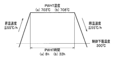
- FIG. 2 shows various PWHT conditions applied to the weld test material.
- the strength of PWHT can be quantified by introducing the concept of Larson-Miller (Lason Miller) heat treatment parameters (hereinafter abbreviated as [P]).
- [P] is represented by the following formula 1, where T represents the PWHT temperature (° C.) and t represents the PWHT time (h).
- the PWHT conditions targeted in this application are (1) 705 ( ⁇ 15) ° C. ⁇ 8 ( ⁇ 1) h, and (2) 705 ( ⁇ 15) ° C. ⁇ 32 ( ⁇ 1) h.
- the ranges are (1) 20.07 to 20.81 and (2) 20.70 to 21.37, respectively.
- Step cooling step cooling (step cooling (SC), FIG. 3) described later was used.
- Min. PWHT (703 ° C. ⁇ 8 h) + SC Charpy impact test (for evaluation of temper embrittlement characteristics)
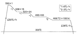
- FIG. 3 shows a graph in which the vertical axis represents temperature and the horizontal axis represents time for explaining the processing conditions for step cooling.
- the step cooling heats the test material, and when the temperature of the test material exceeds 300 ° C., the heating conditions are adjusted so that the temperature rising rate is 50 ° C./h or less, The sample was heated until the temperature reached 593 ° C. Then, after holding at 593 ° C. for 1 hour, the specimen was cooled to 538 ° C. at a cooling rate of 6 ° C./h and held for 15 hours, cooled to 523 ° C.
- the specimen was cooled to 468 ° C. at a cooling rate of 3 ° C./h and held for 100 hours. Then, the sample material was cooled so that the cooling rate was 28 ° C./h or less until the temperature of the sample material became 300 ° C. or less. In this process, the temperature increase rate and the cooling rate are not defined in the temperature range where the temperature of the test material is 300 ° C. or lower.
- -VTr54 (hereinafter referred to as ⁇ vTr54) was calculated as the amount of embrittlement.
- the temper embrittlement susceptibility of the weld metal is comprehensively judged from both vTr54 and ⁇ vTr54.
- a value obtained by adding 3 times ⁇ vTr54 to vTr54 was defined as a temper embrittlement characteristic value.
- step cooling is an accelerated test and that the actual machine has been operating for several decades, it is considered that the actual machine weld metal causes embrittlement three times the amount of embrittlement due to step cooling.
- the coefficient of ⁇ vTr54 (3 in the present application) is 1.5 ⁇ 2.0 ⁇ 2.5 ⁇ as well as the creep performance.
- vE-30 ° C. a three-point average of impact values at ⁇ 30 ° C. (hereinafter referred to as vE-30 ° C.) is 100 J or more, ⁇ , 80 J or more and less than 100 J is ⁇ , and 80 J or less is ⁇ . evaluated.
- ⁇ vTr54 of 5 ° C. or less was evaluated as “ ⁇ ”
- 5 ° C. and less than 11 ° C. was evaluated as ⁇
- 11 ° C. or more was evaluated as “X”.
- the temper embrittlement characteristic value the case where vTr54 + 3 ⁇ vTr54 is ⁇ 30 ° C. or lower is evaluated as “ ⁇ ”, the case where ⁇ 30 ° C. is exceeded and below 0 ° C. is evaluated as “ ⁇ ”, and the case where 0 ° C. is exceeded
- SR crack resistance evaluation test (ring crack test)
- SR Stress relief
- PWHT low-alloy heat-resistant steel
- SR cracking occurs at the old ⁇ grain boundary during SR.
- SR cracking is caused by the superposition of carbide precipitation in crystal grains due to SR and segregation of impurities in old ⁇ grain boundaries, resulting in an excessive strength difference between the crystal grains and the old ⁇ grain boundary interface. This occurs when the old ⁇ grain boundaries weakened to a certain extent cannot resist the residual stress.
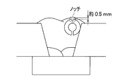
- FIG. 4A A test method called a ring crack test was applied to the SR crack resistance evaluation of the weld metal in the present application.
- the shape of the test piece is shown in FIG. 4B.
- FIG. 4C the slit was TIG welded with the slit caulked to about 0.05 mm, and a residual stress was loaded directly under the U groove.
- SR 625 ° C. ⁇ 10 h
- No. Nos. 11 to 16 were inferior in welding workability because any one of the values of metal carbonate for CO 2 , alkali metal oxide for alkali metal and F for fluorine compound was outside the scope of the present invention.
- the C content was less than the lower limit, so the toughness, embrittlement amount, temper embrittlement characteristics, and creep rupture performance were poorly evaluated.
- No. No. 18 was poor in evaluation of toughness, embrittlement, temper embrittlement characteristics, SR cracking resistance, and welding workability because the C content exceeded the upper limit.
- No. 19 had Si content less than a lower limit, evaluation of toughness, the amount of embrittlement, creep rupture performance, and welding workability was bad.
- No. 20 was poor in evaluation of the embrittlement amount and temper embrittlement characteristics because the Si content exceeded the upper limit.
- No. No. 21 had a Mn content lower than the lower limit, so the toughness evaluation was poor.
- No. No. 22 had an Mn content exceeding the upper limit, and therefore the evaluation of the embrittlement amount, temper embrittlement characteristics, and creep rupture performance was poor.
- Cr content was less than the lower limit of No. 23, evaluation of toughness and SR crack resistance was poor.
- No. 24 since the Cr content exceeded the upper limit, evaluation of toughness, embrittlement, temper embrittlement characteristics, creep rupture performance, and SR crack resistance was poor.
- No. No. 31 was poor in evaluation of toughness and creep rupture performance because the B content was less than the lower limit.
- No. No. 32 was poor in evaluation of SR cracking resistance because the B content exceeded the upper limit.
- No. 33 had poor evaluation of toughness and welding workability.
- No. No. 35 was poor in evaluation of toughness, temper embrittlement characteristics, creep rupture performance, and welding workability because the Fe content was less than the lower limit.
- No. No. 36 was poor in evaluation of toughness, embrittlement, temper embrittlement characteristics, and creep rupture performance because the Fe content exceeded the upper limit.
Abstract
Description
石油精製リアクタ用途の鋼材の溶接に供せられる溶接材料としては、優れたクリープ性能と、それに追随する諸性能である靭性、焼戻脆化特性、耐SR割れ性(応力除去焼鈍時に粒界割れを起こさないこと)、および溶接作業性とを両立することが要求されている。
そして前記のとおり、2.25Cr-1Mo鋼よりも高強度な2.25Cr-1Mo-V鋼製リアクタの適用が進められている。しかしながら、2.25Cr-1Mo-V鋼製リアクタにおいても、その操業条件が高温・高圧化する傾向にあり、従来の溶接材料では昨今の高温強度、特にクリープ破断性能の要求を満足しないという問題があった。
本発明者らは、優れたクリープ強度を有し、且つ靭性、焼戻脆化特性、耐SR割れ性に優れた2.25Cr-1Mo-V鋼溶着金属の形成に際して、そのクリープ性能の改善手段として(1)炭化物の析出形態制御、および(2)ミクロ組織制御という着想を得た。
前記の(2)の実現には、旧γ粒界に優先的に炭化物を形成してすべりを阻害する合金元素の添加、および焼入れ性を低下させる合金元素の添加、あるいは焼入れ性を増加させる合金元素の低減が有効であり、本願ではCrおよびMnに着目した。特に、Crを適度に低減することで、熱処理時の微細な炭化物の結晶粒内への析出を促進し、この微細な炭化物のピン留め効果によってクリープ転位の拡散を抑制するという効果が得られることを見出した。これら合金元素の添加方法は上項と同様である。
さらに、従来技術において構成される何れの溶接材料も、クリープ特性について「PWHT条件:705℃×32h、クリープ破断試験条件:540℃/210MPa」という、今までに類を見ない厳しい直近の市場要求を満たすことはできない。
さらに、被覆アーク溶接棒は、被覆アーク溶接棒の心線および被覆剤のいずれか一方または両方に所定の成分を所定量含有することで、溶接金属のクリープ破断性能、靭性、焼戻脆化特性、耐SR割れ性や、溶接作業性が向上する。なお、溶接作業性とは、アーク安定性、スパッタ発生量、スラグ剥離性、ビードなじみ性、ビード外観などの観点に基づくものである。
本発明の被覆アーク溶接棒は、被覆アーク溶接棒全質量あたり、被覆剤中に、金属炭酸塩をCO2換算値で5~10質量%、アルカリ金属酸化物をアルカリ金属換算値で0.4~2.0質量%、フッ素化合物をF換算値で1.0~5.0質量%含むものである。
さらに、被覆アーク溶接棒は、被覆アーク溶接棒の心線および被覆剤のいずれか一方または両方の合計で、被覆アーク溶接棒全質量あたり、C、Si、Mn、Cr、Mo、V、Nb、B、Mg、Feを所定量含み、不可避不純物として、Cu,Ni,Ti,Al,Ta,Co,およびWの総和を所定量以下、S,Sn,As,Sb,Pb,およびBiの総和を所定量以下としたものである。
以下、各構成について説明する。
金属炭酸塩はアーク熱によって金属酸化物とCO2に分解する。そして前者はスラグを形成して溶接ビードを保護し、後者はアーク雰囲気中の水素分圧を下げて溶着金属中の拡散性水素量を低減させるため、被覆剤中に添加する。この金属炭酸塩はMgCO3や、CaCO3,BaCO3,Na2CO3など、特に限定されるものではない。しかしながら、その含有量が少なすぎるとスラグ生成量が不足してビード外観が劣化するだけでなく、溶着金属中の拡散性水素量が増加して低温割れ感受性が増加する。特に、本願が対象とする高強度2.25C-1Mo-V鋼の様な強度の高い鋼種に対して、溶着金属中の拡散性水素量の増加は施工上極めて大きな問題となる。一方、これらの金属炭酸塩を過剰に添加すると、溶融スラグの粘度が増加して溶融スラグが先行しやすくなるため、溶接ビードのなじみ性が悪化し、スラグ巻き込みなどの溶接欠陥を誘発する。よって、被覆アーク溶接棒全質量あたりの金属炭酸塩の含有量は、CO2換算値で換算して5~10質量%とする。
アルカリ金属酸化物は被覆を形成するバインダの役割を果たし、また心線へと固着させるために被覆剤中に添加する水ガラス中に含有される。その化学的組成としてNa2OやK2O、Li2O等が挙げられるが、これらアルカリ金属酸化物は被覆アーク溶接棒の溶接作業性にも影響を与える。これらアルカリ金属酸化物が少なすぎても多すぎても、即ち、水ガラス添加量が少なすぎても多すぎても溶接作業性、特にアーク安定性に悪影響を与える。よって、被覆アーク溶接棒全質量あたりの含有量は、アルカリ金属換算値で0.4~2.0質量%とする。
フッ素化合物はスラグ形成剤として被覆剤に添加する。このフッ素化合物はBaF2や、CaF2,KF,NaF,AlF3などに代表される金属フッ化物だけでなく、K2SiF6やPTFEに代表される複合金属フッ化物や高分子重合体など、特に限定されるものではない。しかしながら、その含有量が少なすぎる、または多すぎてもビード形状を悪化させる。よって、被覆アーク溶接棒全質量あたりの含有量は、F換算値で1.0~5.0質量%とする。
Cは溶着金属の焼入れ性、および炭化物の析出形態に大きな影響を及ぼす。溶着金属中のC量が低いとベイナイト変態温度が高くなるため、ベイナイト組織が粗大化し、靭性および焼戻脆化特性を低下させる。また、炭化物の析出量が不十分となり、クリープ破断強度も低下する。一方で、C量が過剰に高くなると、炭化物の析出量が増加してクリープ強度が上昇する一方、析出する炭化物の粗大化が促進され、靭性および焼戻脆化特性が低下するだけでなく、高温割れや低温割れ、SR割れなどの各種割れ感受性を高める。また、アーク安定性が劣化する。よって、被覆アーク溶接棒全質量あたりのC量は0.04~0.15質量%とする。好ましくは、下限は0.05であり、上限は0.10質量%である。
Siは溶着金属の室温強度を確保すると同時に、溶着金属を脱酸・清浄化して靭性を向上させる効果がある。溶着金属中のSi量が低すぎるとそのクリープ強度が低下し、さらに溶着金属中の酸素量が増加して粗大な酸化物を形成するため、靭性を低下させる。また、ビードなじみ性、ビード外観が劣化する。一方で、過剰なSiの添加は焼戻脆化特性を劣化させる。よって、被覆アーク溶接棒全質量あたりのSi量は1.0~1.5質量%とする。好ましくは、下限は1.0質量%であり、上限は1.3質量%である。
MnはCに次いで溶着金属のベイナイト変態温度を下げる元素であるため、Mnの添加によってベイナイト変態点を低下させて微細組織を形成し、靭性の向上を図ることができる。一方、ミクロ組織の微細化に伴うすべりサイトの増加により、そのクリープ強度の低下を招くという相反する効果がある。また、MnはSi同様、溶着金属を脱酸・清浄化してその靭性を向上させる一方、過剰な添加は焼戻脆化特性を低下させる。よって、溶着金属の靭性・焼戻脆化特性とクリープ破断強度の両立の観点から、被覆アーク溶接棒全質量あたりのMn量は0.7~1.2質量%とする。好ましくは、下限は0.8質量%であり、上限は1.2質量%である。
Crは、Mo、Vとともに高強度2.25Cr-1Mo-V鋼の基本成分である。Crは旧γ粒界に優先的に炭化物を形成して室温強度、およびクリープ強度を向上させ、また、耐食性を向上させるために必要不可欠な成分である。本発明者らの研究により、Crの低下は微細な炭化物の析出を促進し、Crの増加は粗大な炭化物の析出を促進することが明らかとなっている。溶着金属中のCr量が少なすぎると、微細な炭化物が過剰に析出して靭性を低下させるだけでなく、耐SR割れ性も劣化させる。一方、Cr量が多くなると、析出する炭化物が粗大化して靭性およびクリープ強度を低下させるだけでなく、不純物の粒界偏析を促進して焼戻脆化特性および耐SR割れ性を劣化させる。よって、被覆アーク溶接棒全質量あたりのCr量は1.3~1.9質量%とする。
Moは、Cr、Vとともに高強度2.25Cr-1Mo-V鋼の基本成分である。Moは炭化物を形成するとともに母相中に固溶して、その室温強度・クリープ破断強度を向上させる。溶着金属中のMo量が少なすぎると、炭化物析出量、および母相中への固溶量が不足してクリープ破断強度を低下させる。一方、Mo量が多くなると、炭化物量、および母相中への固溶量が過剰に増加して強度が著しく増加し、靭性を劣化させる。よって、被覆アーク溶接棒全質量あたりのMo量は0.5~1.0質量%とする。
Vは、Cr、Moとともに高強度2.25Cr-1Mo-V鋼の基本成分である。Vは微細な炭化物を形成することで転位のクリープ拡散を阻害し、室温強度・クリープ破断強度を向上させる。溶着金属中のV量が少なすぎると炭化物の析出量が不足してクリープ破断強度を低下させる。一方、V量が多くなると、炭化物の析出量が過剰に増加し、靭性、焼戻脆化特性および耐SR割れ性を低下させる。また、アーク安定性、スパッタ発生量およびビード外観が劣化する。よって、被覆アーク溶接棒全質量あたりのV量は0.3~0.5質量%とする。
Nbは、V同様、微細炭化物の形成傾向が強く、クリープ強度を向上させる。溶着金属中のNb量が少なすぎると、炭化物の析出量が不足してクリープ強度を低下させる。一方、Nb量が多くなると、炭化物の析出量が過剰に増加し、靭性、焼戻脆化特性および耐SR割れ性を低下させる。また、スパッタ発生量が増加する。よって、被覆アーク溶接棒全質量あたりのNb量は0.02~0.06質量%とする。
Bは微量な添加で溶着金属の焼入れ性を高め、その組織を微細化して靭性を向上させるとともに、クリープ強度をも向上させる効果がある。溶着金属中のB量が少なすぎると、組織が粗大化して靭性が低下し、またクリープ破断強度も低下する。一方、B量が多くなると、耐SR割れ性を著しく低下させる。よって、被覆アーク溶接棒全質量あたりのB量は0.005~0.015質量%とする。
Mgは溶着金属を脱酸・清浄化して靭性を向上させるとともに、溶接時のアーク安定性・再アーク性を向上させる。溶着金属中のMg量が少なすぎると、溶着金属中の酸素量が増加して粗大な酸化物を形成し、その靭性が低下するとともに、アーク安定性およびスパッタ発生量が不良となる。一方、Mg量が多くなってもアーク安定性、スパッタ発生量およびビード外観が不良となる。よって、被覆アーク溶接棒全質量あたりのMg量は0.05~0.15質量%とする。好ましくは、下限は0.05質量%であり、上限は0.10質量%である。
Feは溶着金属を構成する主成分であり、主として被覆アーク溶接棒の心線より添加されるが、被覆剤から添加されてもよい。特に、被覆剤から鉄粉あるいは合金鉄の形で添加することで、溶着効率を高めることが出来る。その添加量が少なすぎても多すぎても、他の合金成分の添加効果が十分に得られないため、被覆アーク溶接棒全質量あたりのFe量は60~75質量%とする。またFeはその添加量が60質量%未満であると、スラグ剥離性およびビード外観が劣化する。
本発明においては、不可避不純物として、Cu,Ni,Ti,Al,Ta,Co,およびWの総和が0.10質量%以下、S,Sn,As,Sb,Pb,およびBiの総和が0.10質量%以下である。
Cu,Ni,Ti,Al,Ta,Co,およびWの総和が0.10質量%を超えるとスパッタ発生量が増加する。更に1.00質量%を超えるとアーク安定性も劣化する。
被覆アーク溶接棒は中実の心線および被覆剤にて構成し、被覆剤の質量(=被覆率)は被覆アーク溶接棒全質量に対して25~40質量%とした。被覆アーク溶接棒の化学組成を表1、2に示す。なお、本発明の範囲を満たさないものについては、数値に下線を引いて示す。


本願の実施例に用いた溶接試験体の開先形状を図1Aに示す。試験板にはASTMA387. Gr.22鋼などの2.25Cr-1Mo鋼や、図1Bに示すように、開先面を供試材で2~3層程度バタリング溶接を実施したJIS G3106 SM490A鋼などの炭素鋼を用いても良い。何れの試験板を用いても試験結果は同一であるから、本願の実施例においては共金系であるASTM A387 Gr.22 Cl.2鋼を用いた。試験板・バッキング板の板厚は20mm、開先形状は20°V開先、ルートギャップは19mmとした。溶接長は300mm~600mmとして1層2パスの振り分け溶接を実施し、その積層数は8層仕上げとした。

溶接試験材に施工した各種PWHT条件を図2に示す。PWHTの強弱はLarson-Miller(ラーソン・ミラー)の熱処理パラメータ(以下[P]と略記)の概念を導入することで、定量化することができる。[P]は下式1にて表され、式中のTはPWHT温度(℃)、tはPWHT時間(h)を表す。
ここで、
Min.PWHT(703℃×8h):シャルピー衝撃試験(図2の(a)条件)
Min.PWHT(703℃×8h)+S.C.:シャルピー衝撃試験(焼戻脆化特性評価用)
Max.PWHT(708℃×32h):クリープ破断試験(図2の(b)条件)
である。
次に、ステップクーリングについて説明する。図3に、ステップクーリングの処理条件を説明するための、縦軸を温度、横軸を時間とするグラフを示す。図3に示すように、ステップクーリングは、供試材を加熱し、供試材の温度が300℃を超えると、昇温速度が50℃/h以下となるように加熱条件を調整して、供試材の温度が593℃に到達するまで加熱した。そして、593℃で1時間保持した後、冷却速度6℃/hで538℃まで供試材を冷却して15時間保持し、同冷却速度で523℃まで冷却して24時間保持、さらに同冷却速度で495℃まで冷却して60時間保持した。次に、冷却速度3℃/hで468℃まで供試材を冷却して100時間保持した。そして、供試材の温度が300℃以下になるまで、冷却速度が28℃/h以下となるように供試材を冷却した。なお、この処理において、供試材の温度が300℃以下の温度域では、昇温速度および冷却速度は規定しない。
溶着金属の靭性・焼戻脆化特性を評価するに際して、PWHT条件を703℃×8h、および703℃×8h+ステップクーリングとした両試験材からISO 148-1準拠の2mm-Vノッチのシャルピー衝撃試験片を採取し、20、0、-18、-30、-50、-70、-90℃の各温度で3本ずつシャルピー衝撃試験を実施した。次に、各温度における試験値を潤滑に通過する相互の遷移曲線から、54Jを示すシャルピー遷移温度(以下vTr54およびvTr’54と表記)を決定、ステップクーリングによるvTr54の変動量(=vTr’54-vTr54、以下ΔvTr54と表記)を脆化量として算出した。
脆化量に関しては、ΔvTr54が5℃以下のものを◎、5℃を超え11℃未満のものを○、11℃以上のものを×と評価した。
焼戻脆化特性値に関しては、vTr54+3ΔvTr54が-30℃以下のものを◎、-30℃を超え0℃以下のものを○、0℃を超えるものを×と評価した。
vTr54:PWHT後に54Jを示すシャルピー遷移温度(℃)
vTr’54:PWHT+ステップクーリング後に54Jを示すシャルピー遷移温度(℃)
ΔvTr54(=vTr’54-vTr54):ステップクーリングによる脆化量(℃)
vTr54+3ΔvTr54:焼戻脆化特性(℃)
である。
PWHT条件を708℃×32hとした溶接試験材よりISO 204準拠のクリープ破断試験片を採取し、試験温度を540℃、負荷応力を210MPaとしてクリープ破断試験を実施し、その破断時間を調査した。本実施例において、破断時間(以下Trと表記)が1500h以上のものを◎、1500h未満1000h以上のものを○、1000h未満のものを×と評価した。
Cr-Mo鋼を初めとした低合金耐熱鋼製圧力容器の製作時には、PWHTの施工以前に、製作中の構造物の残留応力低減を主たる目的として、しばしばSR(Stressrelief:応力除去焼鈍)が施工される。このSR時に旧γ粒界において発生するのがSR割れである。SR割れは、SRによる結晶粒内における炭化物の析出、および旧γ粒界における不純物の偏析の二者が重畳することによって結晶粒内と旧γ粒界界面に過剰な強度差が生じ、相対的に弱化した旧γ粒界が残留応力に抗し切れなくなることで発生する。
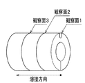
図4Cに示すように、スリットを約0.05mmまでかしめた状態でスリットをTIG溶接して、U溝直下に残留応力を負荷した。次に、TIG溶接後の試験片に図5に示す条件のSR(625℃×10h)を実施した後、図4Dに示すように、試験片を長手方向に3分割し、各断面のノッチ直下を観察して、旧γ粒界におけるSR発生の有無を観察した。観察を行なった6断面(=観察面3×試験数2)中、SR割れの発生が見られないものを◎、SR割れ発生個数が1~2断面のものを○、3断面以上のものを×と評価した。
表2に示す溶接条件下で溶接試験を実施した際の溶接作業性を官能的に評価した。第一に、「アーク安定性」について、アークのバタツキ傾向が弱いものを◎、やや弱いものを○、強いものを×と評価した。第二に、「スパッタ発生量」について、スパッタ発生傾向が弱いものを◎、やや弱いものを○、強いものを×と評価した。第三に、「スラグ剥離性」について、スラグ剥離が容易なものを◎、比較的容易なものを○、困難なものを×と評価した。第四に、「ビードなじみ性」について、ビード止端へのスラグ巻き込み傾向がきわめて弱いものを◎、弱いものを○、強いものを×と評価した。第五に、「ビード外観」について、ビードの波目がきわめて美麗で平滑であるものを◎、美麗で平滑であるものを○、波目が粗く凹凸が激しいものを×と評価した。
これらの結果を表4に示す。

一方、No.11~40は、本発明の範囲を満たさないため、以下の結果となった。
Claims (2)
- 被覆アーク溶接棒全質量あたり、被覆剤中に、金属炭酸塩をCO2換算値で5~10質量%、アルカリ金属酸化物をアルカリ金属換算値で0.4~2.0質量%、フッ素化合物をF換算値で1.0~5.0質量%含み、
被覆アーク溶接棒の心線および被覆剤のいずれか一方または両方の合計で、被覆アーク溶接棒全質量あたり、C:0.04~0.15質量%、Si:1.0~1.5質量%、Mn:0.7~1.2質量%、Cr:1.3~1.9質量%、Mo:0.5~1.0質量%、V:0.3~0.5質量%、Nb:0.02~0.06質量%、B:0.005~0.015質量%、Mg:0.05~0.15質量%、Fe:60~75質量%含み、不可避不純物として、Cu,Ni,Ti,Al,Ta,Co,およびWの総和が0.10質量%以下、S,Sn,As,Sb,Pb,およびBiの総和が0.10質量%以下であることを特徴とする被覆アーク溶接棒。 - 前記被覆アーク溶接棒の心線および被覆剤のいずれか一方または両方の合計で、被覆アーク溶接棒全質量あたり、C:0.05~0.10質量%、Si:1.0~1.3質量%、Mn:0.8~1.2質量%、Cr:1.3~1.9質量%、Mo:0.5~1.0質量%、V:0.3~0.5質量%、Nb:0.02~0.06質量%、B:0.005~0.015質量%、Mg:0.05~0.10質量%、Fe:60~75質量%含み、不可避不純物として、Cu,Ni,Ti,Al,Ta,Co,およびWの総和が0.10質量%以下、S,Sn,As,Sb,Pb,およびBiの総和が0.10質量%以下であることを特徴とする請求項1に記載の被覆アーク溶接棒。
Priority Applications (3)
| Application Number | Priority Date | Filing Date | Title |
|---|---|---|---|
| CN201380071720.0A CN104955609B (zh) | 2013-02-04 | 2013-12-25 | 涂药焊条 |
| KR1020157020955A KR101764040B1 (ko) | 2013-02-04 | 2013-12-25 | 피복 아크 용접봉 |
| EP13873506.3A EP2952287B1 (en) | 2013-02-04 | 2013-12-25 | Covered electrode |
Applications Claiming Priority (2)
| Application Number | Priority Date | Filing Date | Title |
|---|---|---|---|
| JP2013-019561 | 2013-02-04 | ||
| JP2013019561A JP5928726B2 (ja) | 2013-02-04 | 2013-02-04 | 被覆アーク溶接棒 |
Publications (1)
| Publication Number | Publication Date |
|---|---|
| WO2014119189A1 true WO2014119189A1 (ja) | 2014-08-07 |
Family
ID=51261913
Family Applications (1)
| Application Number | Title | Priority Date | Filing Date |
|---|---|---|---|
| PCT/JP2013/084621 WO2014119189A1 (ja) | 2013-02-04 | 2013-12-25 | 被覆アーク溶接棒 |
Country Status (5)
| Country | Link |
|---|---|
| EP (1) | EP2952287B1 (ja) |
| JP (1) | JP5928726B2 (ja) |
| KR (1) | KR101764040B1 (ja) |
| CN (1) | CN104955609B (ja) |
| WO (1) | WO2014119189A1 (ja) |
Cited By (2)
| Publication number | Priority date | Publication date | Assignee | Title |
|---|---|---|---|---|
| CN106238958A (zh) * | 2015-06-09 | 2016-12-21 | 株式会社神户制钢所 | 低氢系带焊皮焊条 |
| CN111843291A (zh) * | 2020-08-13 | 2020-10-30 | 天津市永昌焊丝有限公司 | 一种高强度耐蚀的低镍焊条 |
Families Citing this family (5)
| Publication number | Priority date | Publication date | Assignee | Title |
|---|---|---|---|---|
| CN105499837A (zh) * | 2015-12-18 | 2016-04-20 | 天津市庆鑫祥科技发展有限公司 | 一种自保护药芯焊丝以及焊接方法 |
| JP6829090B2 (ja) * | 2017-01-31 | 2021-02-10 | 株式会社神戸製鋼所 | 被覆アーク溶接棒 |
| CN107234364A (zh) * | 2017-06-12 | 2017-10-10 | 合肥欧仕嘉机电设备有限公司 | 一种用于堆焊的耐磨焊条及其制备方法 |
| CN113613828A (zh) * | 2019-03-26 | 2021-11-05 | 株式会社神户制钢所 | 高Cr铁素体系耐热钢用涂药焊条 |
| US11426823B2 (en) * | 2020-09-28 | 2022-08-30 | Lincoln Global, Inc. | Covered electrode for arc welding high strength steel |
Citations (7)
| Publication number | Priority date | Publication date | Assignee | Title |
|---|---|---|---|---|
| JPS62224497A (ja) * | 1986-03-26 | 1987-10-02 | Nippon Steel Corp | 低水素系被覆ア−ク溶接棒 |
| JPH02220797A (ja) * | 1989-02-21 | 1990-09-03 | Kobe Steel Ltd | Cr―Mo系低合金鋼用被覆アーク溶接棒 |
| JPH10137975A (ja) | 1996-10-31 | 1998-05-26 | Kobe Steel Ltd | 高強度Cr−Mo鋼の被覆アーク溶接金属及び被覆アーク溶接方法 |
| JP2001300768A (ja) | 2000-04-27 | 2001-10-30 | Kobe Steel Ltd | 低合金耐熱鋼用被覆アーク溶接棒 |
| JP2002263883A (ja) | 2001-03-13 | 2002-09-17 | Nkk Corp | 低合金耐熱鋼用被覆アーク溶接棒 |
| JP2008229718A (ja) * | 2007-02-19 | 2008-10-02 | Kobe Steel Ltd | 高強度Cr−Mo鋼の溶接金属 |
| WO2012124529A1 (ja) * | 2011-03-11 | 2012-09-20 | 株式会社神戸製鋼所 | 耐焼戻し脆化特性に優れた溶接金属 |
Family Cites Families (3)
| Publication number | Priority date | Publication date | Assignee | Title |
|---|---|---|---|---|
| CN87102782B (zh) * | 1987-04-16 | 1988-08-31 | 冶金工业部钢铁研究总院 | 超低氢型焊条 |
| JP3258135B2 (ja) * | 1993-05-24 | 2002-02-18 | 株式会社神戸製鋼所 | 高強度Cr−Mo鋼用サブマージアーク溶接方法 |
| JP2010110817A (ja) * | 2008-10-11 | 2010-05-20 | Kobe Steel Ltd | 低水素系被覆アーク溶接棒 |
-
2013
- 2013-02-04 JP JP2013019561A patent/JP5928726B2/ja not_active Expired - Fee Related
- 2013-12-25 EP EP13873506.3A patent/EP2952287B1/en not_active Not-in-force
- 2013-12-25 KR KR1020157020955A patent/KR101764040B1/ko active IP Right Grant
- 2013-12-25 WO PCT/JP2013/084621 patent/WO2014119189A1/ja active Application Filing
- 2013-12-25 CN CN201380071720.0A patent/CN104955609B/zh not_active Expired - Fee Related
Patent Citations (7)
| Publication number | Priority date | Publication date | Assignee | Title |
|---|---|---|---|---|
| JPS62224497A (ja) * | 1986-03-26 | 1987-10-02 | Nippon Steel Corp | 低水素系被覆ア−ク溶接棒 |
| JPH02220797A (ja) * | 1989-02-21 | 1990-09-03 | Kobe Steel Ltd | Cr―Mo系低合金鋼用被覆アーク溶接棒 |
| JPH10137975A (ja) | 1996-10-31 | 1998-05-26 | Kobe Steel Ltd | 高強度Cr−Mo鋼の被覆アーク溶接金属及び被覆アーク溶接方法 |
| JP2001300768A (ja) | 2000-04-27 | 2001-10-30 | Kobe Steel Ltd | 低合金耐熱鋼用被覆アーク溶接棒 |
| JP2002263883A (ja) | 2001-03-13 | 2002-09-17 | Nkk Corp | 低合金耐熱鋼用被覆アーク溶接棒 |
| JP2008229718A (ja) * | 2007-02-19 | 2008-10-02 | Kobe Steel Ltd | 高強度Cr−Mo鋼の溶接金属 |
| WO2012124529A1 (ja) * | 2011-03-11 | 2012-09-20 | 株式会社神戸製鋼所 | 耐焼戻し脆化特性に優れた溶接金属 |
Cited By (2)
| Publication number | Priority date | Publication date | Assignee | Title |
|---|---|---|---|---|
| CN106238958A (zh) * | 2015-06-09 | 2016-12-21 | 株式会社神户制钢所 | 低氢系带焊皮焊条 |
| CN111843291A (zh) * | 2020-08-13 | 2020-10-30 | 天津市永昌焊丝有限公司 | 一种高强度耐蚀的低镍焊条 |
Also Published As
| Publication number | Publication date |
|---|---|
| CN104955609B (zh) | 2017-05-10 |
| EP2952287B1 (en) | 2017-08-16 |
| EP2952287A4 (en) | 2016-09-28 |
| JP2014147970A (ja) | 2014-08-21 |
| JP5928726B2 (ja) | 2016-06-01 |
| CN104955609A (zh) | 2015-09-30 |
| KR20150101469A (ko) | 2015-09-03 |
| KR101764040B1 (ko) | 2017-08-01 |
| EP2952287A1 (en) | 2015-12-09 |
Similar Documents
| Publication | Publication Date | Title |
|---|---|---|
| JP5977998B2 (ja) | Ni基合金溶接金属、帯状電極及び溶接方法 | |
| KR102511652B1 (ko) | 가스 메탈 아크 용접용 솔리드 와이어 | |
| JP4780189B2 (ja) | オーステナイト系耐熱合金 | |
| WO2014119189A1 (ja) | 被覆アーク溶接棒 | |
| WO2012018074A1 (ja) | フェライト系ステンレス鋼 | |
| JP6097087B2 (ja) | 高強度2.25Cr−1Mo−V鋼用サブマージアーク溶接ワイヤおよび溶接金属の製造方法 | |
| JP5170297B1 (ja) | Ni基耐熱合金用溶接材料ならびにそれを用いてなる溶接金属および溶接継手 | |
| JP2008190035A (ja) | 温水器用フェライト系ステンレス鋼板 | |
| WO2010110387A1 (ja) | 溶接金属並びにその溶接金属によって接合された溶接構造物 | |
| JP6978615B2 (ja) | Tig溶接用溶加材 | |
| JPWO2020039643A1 (ja) | ガスメタルアーク溶接用ソリッドワイヤ | |
| KR20230133347A (ko) | 서브머지드 아크 용접 이음 | |
| JP6235402B2 (ja) | 強度、靭性および耐sr割れ性に優れた溶接金属 | |
| JP7276597B2 (ja) | サブマージアーク溶接用ワイヤおよびそれを用いた溶接継手部の製造方法 | |
| JP6978614B2 (ja) | ガスメタルアーク溶接用ソリッドワイヤおよびガスメタルアーク溶接方法 | |
| JP2017047472A (ja) | サブマージアーク溶接用ワイヤ | |
| JP2018144060A (ja) | Tig溶接用溶加材 | |
| JP2004091860A (ja) | 低合金耐熱鋼用溶接金属 | |
| WO2017038975A1 (ja) | サブマージアーク溶接用ワイヤ | |
| JP7360032B2 (ja) | オーステナイト系耐熱鋼溶接継手 | |
| JP2022120717A (ja) | フラックス入りワイヤ、溶接金属、ガスシールドアーク溶接方法及び溶接継手の製造方法 | |
| JP2022097255A (ja) | フラックス入りワイヤ及びガスシールドアーク溶接方法 | |
| WO2022131333A1 (ja) | Tig溶接用溶加材およびそれを用いた溶接継手部の製造方法 | |
| JP2016120520A (ja) | ガスシールドアーク溶接用ワイヤ |
Legal Events
| Date | Code | Title | Description |
|---|---|---|---|
| 121 | Ep: the epo has been informed by wipo that ep was designated in this application |
Ref document number: 13873506 Country of ref document: EP Kind code of ref document: A1 |
|
| REEP | Request for entry into the european phase |
Ref document number: 2013873506 Country of ref document: EP |
|
| WWE | Wipo information: entry into national phase |
Ref document number: 2013873506 Country of ref document: EP |
|
| ENP | Entry into the national phase |
Ref document number: 20157020955 Country of ref document: KR Kind code of ref document: A |
|
| NENP | Non-entry into the national phase |
Ref country code: DE |