WO2014115249A1 - ポンプ及びポンプの製造方法並びに冷凍サイクル装置 - Google Patents
ポンプ及びポンプの製造方法並びに冷凍サイクル装置 Download PDFInfo
- Publication number
- WO2014115249A1 WO2014115249A1 PCT/JP2013/051216 JP2013051216W WO2014115249A1 WO 2014115249 A1 WO2014115249 A1 WO 2014115249A1 JP 2013051216 W JP2013051216 W JP 2013051216W WO 2014115249 A1 WO2014115249 A1 WO 2014115249A1
- Authority
- WO
- WIPO (PCT)
- Prior art keywords
- heat transfer
- transfer plate
- stator
- pump
- substrate
- Prior art date
Links
Images


Classifications
-
- F—MECHANICAL ENGINEERING; LIGHTING; HEATING; WEAPONS; BLASTING
- F04—POSITIVE - DISPLACEMENT MACHINES FOR LIQUIDS; PUMPS FOR LIQUIDS OR ELASTIC FLUIDS
- F04D—NON-POSITIVE-DISPLACEMENT PUMPS
- F04D13/00—Pumping installations or systems
- F04D13/02—Units comprising pumps and their driving means
- F04D13/06—Units comprising pumps and their driving means the pump being electrically driven
- F04D13/0606—Canned motor pumps
- F04D13/064—Details of the magnetic circuit
-
- F—MECHANICAL ENGINEERING; LIGHTING; HEATING; WEAPONS; BLASTING
- F04—POSITIVE - DISPLACEMENT MACHINES FOR LIQUIDS; PUMPS FOR LIQUIDS OR ELASTIC FLUIDS
- F04D—NON-POSITIVE-DISPLACEMENT PUMPS
- F04D29/00—Details, component parts, or accessories
- F04D29/58—Cooling; Heating; Diminishing heat transfer
- F04D29/5813—Cooling the control unit
-
- F—MECHANICAL ENGINEERING; LIGHTING; HEATING; WEAPONS; BLASTING
- F04—POSITIVE - DISPLACEMENT MACHINES FOR LIQUIDS; PUMPS FOR LIQUIDS OR ELASTIC FLUIDS
- F04D—NON-POSITIVE-DISPLACEMENT PUMPS
- F04D29/00—Details, component parts, or accessories
- F04D29/58—Cooling; Heating; Diminishing heat transfer
- F04D29/586—Cooling; Heating; Diminishing heat transfer specially adapted for liquid pumps
- F04D29/5893—Cooling; Heating; Diminishing heat transfer specially adapted for liquid pumps heat insulation or conduction
-
- H—ELECTRICITY
- H02—GENERATION; CONVERSION OR DISTRIBUTION OF ELECTRIC POWER
- H02K—DYNAMO-ELECTRIC MACHINES
- H02K11/00—Structural association of dynamo-electric machines with electric components or with devices for shielding, monitoring or protection
- H02K11/20—Structural association of dynamo-electric machines with electric components or with devices for shielding, monitoring or protection for measuring, monitoring, testing, protecting or switching
- H02K11/25—Devices for sensing temperature, or actuated thereby
-
- H—ELECTRICITY
- H02—GENERATION; CONVERSION OR DISTRIBUTION OF ELECTRIC POWER
- H02K—DYNAMO-ELECTRIC MACHINES
- H02K11/00—Structural association of dynamo-electric machines with electric components or with devices for shielding, monitoring or protection
- H02K11/30—Structural association with control circuits or drive circuits
- H02K11/33—Drive circuits, e.g. power electronics
Definitions
- the present invention relates to a pump, a pump manufacturing method, and a refrigeration cycle apparatus.
- a wiring board is disposed on the upper surface of a mold stator, and a driving element for supplying a driving current to the stator winding is mounted on the wiring board.
- the stator and the wiring board are molded with an electrically insulating resin material.
- the heat sink which radiates the heat which a drive element emits is embed
- the motor shown in the following Patent Document 2 is configured to detect the temperature from a lead leg with good thermal conductivity by fixing a temperature detection element in the vicinity of the drive element by soldering. According to this prior art, the temperature followability can be improved, and the temperature detection element can be attached only by the soldering operation, so that the temperature detection element has good followability and productivity. Is obtained.
- each drive element is provided with a temperature detection element so that it can cope with any of the drive elements becoming hot.
- the cost increases.
- the layout of electronic components may be restricted when the board is downsized or the number of components is increased.
- the present invention has been made in view of the above, and an object of the present invention is to obtain a pump, a pump manufacturing method, and a refrigeration cycle apparatus that can accurately detect the temperature of a drive element without causing an increase in cost. .
- the present invention provides a stator in which a coil is wound around a plurality of teeth provided with an insulating portion of a stator core, and a substrate on which a drive element is mounted.
- a pump including a mold stator formed integrally with a thermosetting resin
- the substrate includes a temperature detection element mounted on the same surface as the substrate surface on which the driving element is mounted, A heat transfer plate that is provided on the opposite side of the drive element and the temperature detection element and thermally connects these elements, and the heat transfer plate is thermally connected to the drive element and the temperature detection element And a heat transfer plate holder for holding the heat transfer plate.
- the temperature of the drive element and the temperature of the temperature detection element are detected by detecting the temperature of the drive element via the heat transfer plate disposed so as to cover the one or more drive elements and the temperature detection element.
- the temperature of the drive element can be accurately detected without increasing the cost.
- FIG. 1 is a configuration diagram of a heat pump hot water supply apparatus using a pump according to an embodiment of the present invention.
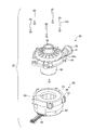
- FIG. 2 is an exploded perspective view of the pump.
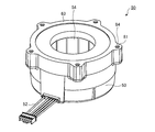
- FIG. 3 is a perspective view of the mold stator.
- FIG. 4 is a cross-sectional view of the mold stator.
- FIG. 5 is an exploded perspective view of the stator assembly.
- FIG. 6 is a block diagram of the heat transfer plate assembly.
- FIG. 7 is a view of the heat transfer plate assembly as viewed from the side opposite to the stator.
- FIG. 8 is a perspective view of the heat transfer plate assembly as viewed from the side opposite to the stator.
- FIG. 9 is a perspective view of the stator before the heat transfer plate assembly is assembled.
- FIG. 10 is a perspective view of the stator assembled with the heat transfer plate assembly.
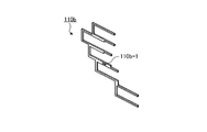
- FIG. 11 is a perspective view of a substantially comb-shaped heat transfer plate viewed from the side opposite to the stator.
- FIG. 12 is a perspective view of the substantially uneven heat transfer plate as viewed from the side opposite to the stator.
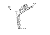
- FIG. 13 is a perspective view of the heat transfer plate holder as seen from the side opposite to the stator.
- FIG. 14 is a perspective view of the heat transfer plate holder as seen from the stator side.
- FIG. 15 is an exploded perspective view of the pump unit.
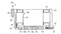
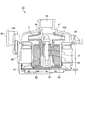
- FIG. 16 is a sectional view of the pump.
- FIG. 17 is a perspective view of the casing as seen from the shaft support portion side.
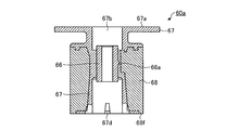
- FIG. 18 is a cross-sectional view of the rotor portion (AA cross-sectional view of FIG. 20).
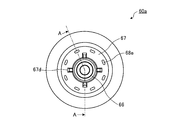
- FIG. 19 is a side view of the rotor portion viewed from the impeller mounting portion side.
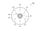
- FIG. 20 is a side view of the rotor portion viewed from the side opposite to the impeller mounting portion.
- FIG. 21 is an enlarged sectional view of the sleeve bearing.
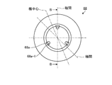
- FIG. 22 is a sectional view of the resin magnet (a sectional view taken along the line BB in FIG. 23).
- FIG. 23 is a side view of the resin magnet as viewed from the protrusion side.
- FIG. 24 is a side view of the resin magnet as viewed from the opposite side of the protrusion.
- FIG. 25 is a perspective view of the rotor portion viewed from the impeller mounting portion side.
- FIG. 26 is a perspective view of the rotor portion viewed from the side opposite to the impeller mounting portion.
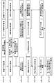
- FIG. 27 is a diagram showing a manufacturing process of the pump.
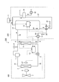
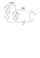
- FIG. 28 is a conceptual diagram showing a circuit of a refrigeration cycle apparatus using a refrigerant-water heat exchanger.
- FIG. 1 is a configuration diagram of a heat pump hot water supply apparatus 300 using a pump 10 according to an embodiment of the present invention.
- the heat pump hot water supply apparatus 300 includes a heat pump unit 100, a tank unit 200, and an operation unit 11 on which a user performs a driving operation and the like.
- a heat pump unit 100 includes a compressor 1 that compresses a refrigerant (for example, a rotary compressor, a scroll compressor, etc.), a refrigerant-water heat exchanger 2 that exchanges heat between the refrigerant and water, and a high-pressure unit.
- a decompression device 3 that decompresses and expands the refrigerant
- an evaporator 4 that evaporates the low-pressure two-phase refrigerant
- a refrigerant pipe that connects the compressor 1, the refrigerant-water heat exchanger 2, the decompression device 3, and the evaporator 4 in an annular shape.
- a refrigerant circuit is constituted by the compressor 1, the refrigerant-water heat exchanger 2, the decompression device 3, the evaporator 4, and the refrigerant pipe 15 that connects these in an annular shape.
- the heat pump unit 100 includes, as temperature detection units, a boiling temperature detection unit 8 of the refrigerant-water heat exchanger 2, a feed water temperature detection unit 9 of the refrigerant-water heat exchanger 2, and an outside air temperature detection unit 17. I have.
- the heat pump unit 100 includes a heat pump unit control unit 13.
- the heat pump unit control unit 13 receives signals from the pressure detection device 5, the boiling temperature detection unit 8, the feed water temperature detection unit 9, and the outside air temperature detection unit 17, and controls the rotation speed of the compressor 1 and the decompression device 3. The opening degree control and the rotational speed control of the fan motor 6 are performed.
- the tank unit 200 includes a hot water tank 14 that stores hot water heated by exchanging heat with a high-temperature and high-pressure refrigerant in the refrigerant-water heat exchanger 2, and a bath water reheating heat exchanger that replenishes the bath water.
- a bath water circulation device 32 connected to the bath water reheating heat exchanger 31, a pump 10 which is a hot water circulation device disposed between the refrigerant-water heat exchanger 2 and the hot water tank 14, and a refrigerant—
- a hot water circulation pipe 16 connecting the water heat exchanger 2 and the hot water tank 14, a mixing valve 33 connected to the refrigerant-water heat exchanger 2, the hot water tank 14 and the bath water reheating heat exchanger 31;
- a bath water recirculation pipe 37 for connecting the hot water tank 14 and the mixing valve 33.
- the refrigerant-water heat exchanger 2, the hot water tank 14, the pump 10, and the hot water circulation pipe 16 constitute a water circuit.
- the tank unit 200 includes a tank water temperature detection unit 34, a post-reheating water temperature detection unit 35 that detects the water temperature after passing through the bath water reheating heat exchanger 31, and a mixing valve 33 as temperature detection units. And a post-mixing water temperature detection unit for detecting the water temperature after passing through.
- the tank unit 200 includes a tank unit controller 12.
- the tank unit controller 12 receives signals from the in-tank water temperature detector 34, the reheated water temperature detector 35, and the mixed water temperature detector 36, and controls the rotational speed of the pump 10 and the opening / closing control of the mixing valve 33. I do. Furthermore, the tank unit 200 transmits and receives signals to and from the heat pump unit control unit 13 and the operation unit 11.
- the operation unit 11 is a remote control or an operation panel provided with a switch or the like for a user to set a temperature of hot water or give a hot water instruction.
- FIG. 1 the normal boiling operation operation in the heat pump type hot water supply apparatus 300 configured as described above will be described.
- the heat pump unit 100 performs the boiling operation.
- the heat pump unit controller 13 controls the rotational speed of the compressor 1, the opening degree of the decompressor 3, and the fan based on the detected values of the pressure detector 5, the boiling temperature detector 8, and the feed water temperature detector 9. The number of revolutions of the motor 6 is controlled.
- the detection value of the boiling temperature detection part 8 is transmitted / received between the heat pump unit control part 13 and the tank unit control part 12, and the tank unit control part 12 is the temperature detected by the boiling temperature detection part 8.
- the number of rotations of the pump 10 is controlled so as to reach the target boiling temperature.
- the temperature of the high-temperature and high-pressure refrigerant discharged from the compressor 1 decreases while radiating heat to the water supply circuit side by the refrigerant-water heat exchanger 2.
- the high-pressure and low-temperature refrigerant that has radiated heat and passed through the refrigerant-water heat exchanger 2 is decompressed by the decompression device 3.
- the refrigerant that has passed through the decompression device 3 flows into the evaporator 4 where it absorbs heat from outside air.
- the low-pressure refrigerant exiting the evaporator 4 is sucked into the compressor 1 and circulates to form a refrigeration cycle.
- the water in the lower part of the hot water tank 14 is led to the refrigerant-water heat exchanger 2 by driving the pump 10 which is a hot water circulation device.
- water is heated by heat radiation from the refrigerant-water heat exchanger 2, and the heated hot water is returned to the upper part of the hot water tank 14 through the hot water circulation pipe 16 to be stored.
- the pump 10 is used as a hot water circulation apparatus for circulating hot water in the hot water circulation pipe 16 between the hot water tank 14 and the refrigerant-water heat exchanger 2.
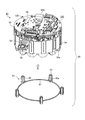
- FIG. 2 is an exploded perspective view of the pump 10.
- the pump 10 includes a pump unit 40 that absorbs and discharges water by rotation of a rotor (described later), a mold stator 50 that drives the rotor, a pump unit 40, and a mold stator. And a tapping screw 160 that is a fastening screw that fastens the screw 50.
- the number of tapping screws 160 is five, for example, but is not limited thereto.
- the pump 10 includes five tapping screws 160 of pilot hole parts 81 (see FIG. 5 described later for details) embedded in the mold stator 50 through screw holes 44a formed in the boss portions 44 of the pump portion 40. It is assembled by fastening to the pilot hole 84.
- the casing 41, the suction port 42, the discharge port 43, the bowl-shaped partition wall component 90, the lead wire 52, the mold resin 53, the stator core 54, and the pump unit installation surface 63 are described below.
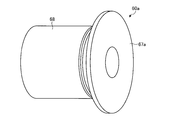
- FIG. 3 is a perspective view of the mold stator 50
- FIG. 4 is a sectional view of the mold stator 50
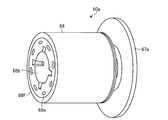
- FIG. 5 is an exploded perspective view of the stator assembly 49
- FIG. 6 is a configuration diagram of the heat transfer plate assembly 120
- FIG. FIG. 8 is a perspective view of the heat transfer plate assembly 120 as viewed from the anti-stator side
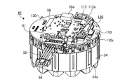
- FIG. 9 is a perspective view of the stator 47 before the heat transfer plate assembly 120 is assembled.
- FIG. 10 is a perspective view of the stator 47 assembled with the heat transfer plate assembly 120
- FIG. 11 is a perspective view of the substantially comb-shaped heat transfer plate 110b seen from the side opposite to the stator
- FIG. 13 is a perspective view of the heat transfer plate holder 112 as seen from the stator side
- FIG. 13 is a perspective view of the heat transfer plate holder 112 as seen from the stator side
- FIG. 14 is a perspective view of the heat transfer plate holder 112 as seen from the stator side.
- 15 is an exploded perspective view of the pump unit 40
- FIG. 16 is a cross-sectional view of the pump 10
- FIG. It is a perspective view of the single 41 from the shaft support portion 46 side.
- the mold stator 50 shown in FIGS. 3 and 4 is obtained by molding the stator assembly 49 (see FIG. 5) with the mold resin 53.
- a flat pump portion installation surface 63 is provided along the outer peripheral edge of one end surface in the axial direction of the mold stator 50, specifically, the end surface on the casing 41 side (see FIG. 2).
- legs 85 (see FIG. 5) of pilot hole parts 81 are embedded in the axial direction at five locations.
- the foot 85 is, for example, a substantially cylindrical resin molded part.
- one end surface (end surface on the pump unit 40 side) of the foot portion 85 becomes a mold pressing portion 82 (see FIG. 4) of the molding die. Therefore, the pilot hole part 81 is exposed in a form embedded inside the pump part installation surface 63 by a predetermined distance. What is exposed is a mold retainer 82 and a pilot hole 84 for the tapping screw 160.
- the lead wire 52 drawn out from the stator assembly 49 is drawn out from the vicinity of the axial end surface of the mold stator 50 opposite to the pump part 40 side.
- the axial positioning of the mold stator 50 during molding with the mold resin 53 is performed by a plurality of heat transfer plate pressing pins 112a (see FIG. 8) formed on the heat transfer plate holder 112.
- the axial end surface serves as an upper mold pressing part. Therefore, the axial end surface (mold pressing surface) of the heat transfer plate pressing pin 112a is exposed from the axial end surface on the substrate 58 side of the mold stator 50 (not shown).
- the axial end surface of the insulating part 56 on the anti-connection side becomes a lower mold pressing part. Therefore, the end surface of the insulating portion 56 on the anti-connection side is exposed from the axial end surface of the mold stator 50 opposite to the substrate 58 side (not shown).
- the positioning of the mold stator 50 in the radial direction at the time of molding is performed by fitting the inner peripheral surface of the stator core 54 to the mold. Therefore, the tip end portion (inner peripheral portion) of the teeth of the stator core 54 is exposed on the inner peripheral portion of the mold stator 50 shown in FIG.
- the stator assembly 49 includes a stator 47 and a pilot hole part 81.
- the stator 47 includes a lead wire 52, a stator core 54 provided with a groove 54a, an insulating portion 56, a coil 57, an IC 58a, a Hall element 58b, a substrate 58, a terminal 59, A lead wire lead part 61 and a heat transfer plate assembly 120 are provided.
- the pilot hole component 81 includes a foot portion 85, protrusions 83 and 85 a provided on the foot portion 85, and a connecting portion 87.
- the stator assembly 49 is manufactured by the following procedure.
- An electromagnetic steel sheet having a thickness of, for example, about 0.1 to 0.7 mm is punched into a strip shape, and an annular stator core 54 is manufactured by laminating the electromagnetic steel sheet by caulking, welding, bonding, or the like.
- the stator core 54 includes a plurality of teeth.
- the tips of the teeth of the stator core 54 are exposed on the inner periphery of the mold stator 50 shown in FIG. Since the stator core 54 shown here has, for example, twelve teeth connected by the thin-walled connecting portion, the tips of the teeth of the stator core 54 are exposed at 12 locations in FIG. However, the teeth visible in FIG. 3 are five of the twelve teeth.
- An insulating portion 56 is applied to the teeth of the stator core 54.
- the insulating portion 56 is molded integrally with the stator core 54 or separately from the stator core 54 using a thermoplastic resin such as PBT (polybutylene terephthalate).
- Concentrated winding coil 57 (see FIG. 4) is wound around the teeth provided with insulating portion 56. Twelve concentrated winding coils 57 are connected to form a three-phase single Y-connection winding.
- a terminal 59 (see FIG. 4) to which a coil 57 (see FIG. 4) of each phase (U phase, V phase, W phase) is connected on the connection side of the insulating portion 56.
- the heat transfer plate assembly 120 is manufactured in parallel. Details of the heat transfer plate assembly 120 will be described later.
- the substrate 58 is attached to the insulating portion 56 on the connection side (side on which the terminal 59 is assembled).
- a substrate fixing protrusion 130 is formed on the insulating portion 56 of the stator 47, and the substrate 58 has an insertion hole (not shown) into which the protrusion 130 is inserted. By inserting the protrusion 130 into the insertion hole, the substrate 58 is placed on the insulating portion 56, and the substrate 58 is sandwiched between the insulating portion 56 and the heat transfer plate holder 112.
- the substrate 58 includes an IC 58a (driving element) that drives an electric motor (for example, a brushless DC motor), a temperature detecting element 111 that detects the temperature of the driving element that suddenly generates heat when there is an abnormality such as a lock, and the rotation.
- Electronic equipment such as a Hall element 58b (for example, a magnetic pole position detecting element) for detecting the position of the child 60 is mounted. Since the IC 58a and the temperature detection element 111 are mounted on the anti-stator side of the substrate 58, they can also be seen in FIG. 5 (or FIG. 9). However, since the Hall element 58b is mounted on the opposite side to the IC 58a, it is not visible in FIG.
- the IC 58a and the Hall element 58b are defined as electronic components.
- a lead wire lead-out component 61 and a heat transfer plate assembly 120 that lead out the lead wire 52 are attached to the substrate 58 at a notch near the outer peripheral edge thereof.
- the substrate 58 to which the lead wire lead-out component 61 and the heat transfer plate assembly 120 are attached is fixed to the insulating portion 56 by the heat transfer plate holder 112, and the terminal 59 and the substrate 58 are soldered to the stator 47.
- the stator assembly 49 is completed by assembling the pilot hole part 81.
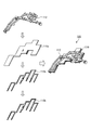
- a heat transfer plate assembly 120 shown in FIG. 6 includes a heat transfer plate 110 formed by laminating a substantially uneven heat transfer plate 110a and a substantially comb-shaped heat transfer plate 110b, and the heat transfer plate 110 is locked. And a heat transfer plate holder 112 that performs.
- the substantially uneven heat transfer plate 110a and the substantially comb-shaped heat transfer plate 110b are manufactured by punching, milling, etching, or the like from a thin metal plate having excellent thermal conductivity such as copper.
- the heat transfer plate holder 112 is formed by injection molding a thermoplastic resin such as PBT (polybutylene terephthalate).
- the heat transfer plate 110a having a substantially concave and convex shape and the heat transfer plate 110b having a substantially comb shape are stacked so as to cover the opposite end surface of the drive element and the side surface of the drive element, thereby efficiently generating heat of the drive element. This can be transmitted to the detection element 111.
- the heat transfer plate 110 shown in FIG. 6 is composed of three thin metal flat plates as an example. However, by changing the shape of the thin metal flat plates and the number of stacked layers, the heat transfer plate 110 can correspond to a drive element having an arbitrary shape. It is possible.
- the shape of the substantially uneven heat transfer plate 110a and the shape of the substantially comb-shaped heat transfer plate 110b are formed so as to cover only the driving elements that generate a large amount of heat. It is possible to reduce the amount of use of the thin metal flat plate, and to reduce the processing cost of the thin metal flat plate.
- the substantially comb-shaped heat transfer plate 110 b has a substantially U-shape disposed around the drive element and the temperature detection element 111.
- the substantially comb-shaped heat transfer plate 110b is configured to include a plurality of substantially U-shaped members so that the side surfaces of the drive elements and the temperature detection element 111 can be enclosed.
- the substantially uneven heat transfer plate 110a is formed in an uneven shape so as to cover the entire end surface on the opposite side of the driving element and the end surface on the opposite side of the temperature detecting element 111. .
- the substantially uneven heat transfer plate 110a is formed so as to cover the entire end surface on the side opposite to the substrate of the drive element, the substantially uneven heat transfer plate 110a also serves as a heat radiating plate. It is possible to suppress the temperature rise of the drive element.
- the substantially uneven heat transfer plate 110 a and the substantially comb-shaped heat transfer plate 110 b are located at positions corresponding to the claws 112 c (see FIG. 14) provided on the heat transfer plate holder 112.
- a substantially square notch 110a-1, 110b-1 may be provided.
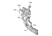
- the heat transfer plate holder 112 has a thin connection shape formed by injection molding of a thermoplastic resin such as PBT (polybutylene terephthalate).
- the heat transfer plate holder 112 is provided with a plurality of protrusion insertion holes 112b (two in the example of FIG. 13) corresponding to the protrusions 130 (see FIG. 5).
- the heat transfer plate holder 112 is fixed to the stator 47 together with the substrate 58 by inserting the protrusions 130 into the protrusion insertion holes 112b. Therefore, it is not necessary to use a separate part for fixing the substrate 58 to the heat transfer plate assembly 120, and the processing cost can be reduced.
- a plurality of heat transfer plate fixing claws 112 c extending toward the substrate side are provided on the substrate side surface (surface on the drive element side) of the heat transfer plate holder 112.
- the heat transfer plate holder 112 is provided with six claws 112c.
- claw 112c latches in predetermined positions, such as the outer peripheral part of a heat transfer board (110a, 110b), and the heat transfer board 110 is hold
- a plurality of heat transfer plate pressing pins 112 a extending toward the outer side of the mold stator 50 are provided on the side opposite to the substrate (the surface opposite to the drive element side) of the heat transfer plate holder 112. Is provided. At least one heat transfer plate pressing pin 112 a is provided on the heat transfer plate holder 112. In the example of FIG. 13, nine heat transfer plate pressing pins 112 a are provided on the heat transfer plate holder 112.
- the pilot hole part 81 is formed by molding a thermoplastic resin such as PBT (polybutylene terephthalate).
- the pilot hole part 81 is configured by a plurality of substantially cylindrical foot portions 85 (for example, five pieces) connected in a ring shape with thin connection portions 87.
- the foot portion 85 is provided with a pilot hole 84 into which the tapping screw 160 is screwed (see FIG. 2).
- the foot portion 85 has a tapered shape that becomes thicker from the exposed end surface (end surface of the mold pressing portion 82 and the protrusion 83) toward the central portion in the axial direction.
- the pilot hole part 81 includes a plurality of protrusions 85a on the outer periphery of the foot 85 for preventing rotation.
- four protrusions 85 a are provided on the outer periphery of the foot 85.
- the protrusion 85a is formed to extend in the height direction (axial direction) of the foot 85 with a predetermined circumferential width. Further, the protrusion 85 a protrudes from the outer peripheral surface of the foot 85 by a predetermined dimension necessary for preventing the rotation of the pilot hole part 81.
- the pilot hole part 81 can be set in a mold once by connecting the substantially cylindrical foot part 85 with the thin connection part 87, and the processing cost can be reduced.
- a plurality of claws (not shown) for assembling the pilot hole part 81 to the stator 47 are provided in the connecting part 87 of the pilot hole part 81, and formed on the outer peripheral part of the stator core 54 of the stator 47.
- pilot hole part 81 is locked to the stator 47, when the stator assembly 49 is molded by the mold resin 53, the mold pressing portion 82 and the projection 83 of the pilot hole part 81 are formed by the mold. By pinching, the pilot hole part 81 is positioned in the axial direction.
- the end surface of the pilot hole part 81 is formed on the mold press part 82.
- the part except for is covered with the mold resin 53. Therefore, since both end surfaces of the pilot hole part 81 are covered with the mold resin 53, it is possible to suppress the exposure of the pilot hole part 81 and improve the quality of the pump 10.
- the mold stator 50 is obtained by integrally molding the prepared hole part 81 assembled to the stator 47 with the mold resin 53. At this time, the pilot hole 84 is formed so as to be exposed. By tightening and assembling the pump unit 40 and the mold stator 50 to the pilot hole 84 with the tapping screw 160 through the screw holes 44a formed in the pump unit 40, the pump unit 40 and the mold stator 50 are firmly connected. Can be assembled (see FIG. 2).
- the pump unit 40 includes the following elements.
- Casing 41 The casing 41 has a fluid suction port 42 and a discharge port 43, and houses the impeller 60b of the rotor 60 therein.
- the casing 41 is molded using a thermoplastic resin such as PPS (polyphenylene sulfide).
- PPS polyphenylene sulfide
- the casing 41 is provided with five boss portions 44 having screw holes 44a used when the pump portion 40 and the mold stator 50 are assembled.
- Thrust bearing 71 The material of the thrust bearing 71 is ceramic such as alumina.
- Rotor 60 Since the rotor 60 is pressed against the casing 41 via the thrust bearing 71 by the pressure difference acting on the front and back of the impeller 60b of the rotor 60 during operation of the pump 10, the thrust bearing 71 is made of ceramic. To ensure wear resistance and slidability.
- Rotor 60 includes a rotor portion 60a and an impeller 60b.
- the rotor portion 60a is provided, for example, inside a ring-shaped (cylindrical or annular) resin magnet 68 (an example of a magnet) obtained by molding a pellet obtained by kneading magnetic powder such as ferrite and resin.
- a cylindrical sleeve bearing 66 (for example, made of carbon) is integrated with a resin portion 67 such as PPE (polyphenylene ether) (see FIG. 18 described later).
- the impeller 60b is a resin molded product such as PPE (polyphenylene ether).
- the rotor part 60a and the impeller 60b are joined together by, for example, ultrasonic welding. Details of the rotor 60a will be described later.
- Shaft 70 The material of the shaft 70 (rotating shaft) is, for example, ceramic such as alumina, SUS, or the like.
- a material such as ceramic or SUS is selected to ensure wear resistance and slidability.
- One end of the shaft 70 is inserted into the shaft support portion 94 of the bowl-shaped partition wall component 90, and the other end of the shaft 70 is inserted into the shaft support portion 46 (see FIG. 17) of the casing 41.
- One end of the shaft 70 inserted into the shaft support portion 94 (see FIG. 16) of the bowl-shaped partition wall component 90 is inserted so as not to rotate with respect to the shaft support portion 94.
- one end of the shaft 70 is substantially D-shaped with a predetermined length (axial direction) cut out of a part of the circle, and the hole of the shaft support portion 94 is also shaped to match the shape of one end of the shaft 70.
- the other end of the shaft 70 inserted into the shaft support portion 46 of the casing 41 is also substantially D-shaped by cutting out a part of a circle having a predetermined length (axial direction), and the shaft 70 extends in the length direction. It is symmetrical. However, the other end of the shaft 70 is rotatably inserted into the shaft support portion 46. The reason why the shaft 70 is symmetrical in the length direction is to allow assembly without being aware of the vertical direction when the shaft 70 is inserted into the shaft support portion 94 (see FIG.
- O-ring 80 The material of the O-ring 80 is EPDM (ethylene-propylene-diene rubber) or the like. The O-ring 80 performs sealing between the casing 41 of the pump unit 40 and the bowl-shaped partition wall component 90. In pumps mounted on water heaters and the like, heat seals and long life are required for seals around water, so materials such as EPDM are used to ensure resistance.
- Cage-like partition wall component 90 Cage-like wall partition component 90 is formed using, for example, a thermoplastic resin such as PPE (polyphenylene ether).
- the bowl-shaped partition wall component 90 includes a bowl-shaped partition wall portion 90 a that is a fitting portion with the mold stator 50 and a flange portion 90 b.
- the bowl-shaped partition wall 90a is composed of a circular bottom and a cylindrical partition.
- a shaft support portion 94 into which one end of the shaft 70 is inserted is provided at a substantially central portion of the inner surface of the bottom portion of the bowl-shaped partition wall portion 90a (see FIG. 16).
- a plurality of ribs 92 are formed radially on the outer surface of the bottom of the bowl-shaped partition wall 90a in the radial direction.
- a plurality of reinforcing ribs (not shown) that reinforce the flange 90b are radially formed in the flange 90b.
- the flange portion 90b is provided with an annular rib (not shown) that fits in the pump portion installation surface 63 (see FIG. 3) of the mold stator 50.
- holes 90d through which the tapping screw 160 (see FIG. 2) passes are formed in the flange portion 90b at five locations.
- an annular O-ring storage groove 90c for storing the O-ring 80 is formed on the surface of the flange portion 90b on the casing 41 side.
- the pump 10 In the pump 10, after the O-ring 80 is installed in the bowl-shaped partition part 90, the shaft 70, the rotor 60, and the thrust bearing 71 are installed in the bowl-shaped partition part 90. Then, the pump part 40 is assembled by assembling the casing 41 to the bowl-shaped partition wall part 90. As shown in FIG. 2, the pump unit 40 is assembled to the mold stator 50, and the pump 10 is assembled by fixing the pump unit 40 and the mold stator 50 with a tapping screw 160 or the like.
- the rib 92 provided on the bottom of the bowl-shaped partition wall component 90 and the groove (not shown) of the mold stator 50 are fitted to each other, thereby positioning the pump unit 40 and the mold stator 50 in the circumferential direction.
- the rotor 60 is accommodated inside the bowl-shaped partition wall 90a.
- a shaft 70 is inserted into the shaft support portion 94 of the bowl-shaped partition wall component 90, and the rotor 60 is fitted on the shaft 70. Therefore, in order to ensure the coaxiality of the mold stator 50 and the rotor 60, the gap between the inner periphery of the mold stator 50 and the outer periphery of the bowl-shaped partition wall 90a is preferably as small as possible. For example, the gap is selected to be about 0.02 to 0.06 mm.
- FIG. 18 is a cross-sectional view of the rotor portion 60a (AA cross-sectional view of FIG. 20)
- FIG. 19 is a side view of the rotor portion 60a viewed from the impeller mounting portion 67a side
- FIG. FIG. 21 is an enlarged sectional view of the sleeve bearing 66
- FIG. 22 is a sectional view of the resin magnet 68 (BB sectional view of FIG. 23)
- FIG. FIG. 24 is a side view of the resin magnet 68 viewed from the side opposite to the projection 68a.
- FIG. 25 is a perspective view of the rotor 60a viewed from the impeller mounting portion 67a. These are the perspective views which looked at the rotor part 60a from the opposite side of the impeller attachment part 67a.
- the rotor section 60a will be described with reference to FIGS. As shown in FIGS. 18 to 26, the rotor section 60a includes at least the following elements. (1) Resin magnet 68; (2) sleeve bearing 66; (3) Resin portion 67; The resin portion 67 is a portion made of a thermoplastic resin such as PPE (polyphenylene ether). An impeller attachment portion 67 a for attaching the impeller 60 b is formed in the resin portion 67.
- the resin magnet 68 and the sleeve bearing 66 are integrally formed by the resin portion 67.
- the resin magnet 68 has a substantially ring shape (cylindrical shape) and is formed of pellets obtained by kneading a magnetic powder such as ferrite and a resin.
- the sleeve bearing 66 (for example, made of carbon) is provided inside the resin magnet 68.
- the sleeve bearing 66 has a cylindrical shape. Since the sleeve bearing 66 rotates by being fitted to the shaft 70 assembled in the bowl-shaped partition wall component 90 of the pump 10, for example, PPS (polyphenylene sulfide) added with sintered carbon or carbon fiber suitable for the material of the bearing is used. It is made of thermoplastic resin or ceramic.
- the sleeve bearing 66 includes a draft taper (not shown) whose outer diameter decreases from the center in the approximate axial direction toward both ends, and is, for example, a hemispherical protrusion 66a (see FIG. 21) that prevents rotation on the outer peripheral surface at the approximate center in the axial direction. A plurality of reference).
- a portion of the resin portion 67 formed in contact with the end surface of the resin magnet 68 on the impeller mounting portion 67a side is provided with a magnet pressing portion (not shown) provided on the upper mold of the resin molding die.
- a recess 67b is formed.
- the recess 67b is formed at a substantially central portion in the radial direction.
- the recess 67b is formed at a position substantially opposite to the protrusion 68a (see FIG. 19) of the resin magnet 68 in the axial direction.
- a plurality of impeller positioning holes 67c for attaching the impeller 60b are formed in the impeller attaching portion 67a.
- three impeller positioning holes 67c are formed at substantially equal intervals in the circumferential direction.
- the impeller positioning hole 67c passes through the impeller attachment portion 67a.
- Each impeller positioning hole 67 c is formed on the intermediate radial extension line of two of the three protrusions 68 a of the resin magnet 68.
- the impeller mounting portion 67a has gates 67e (resin injection ports) used at the time of molding the rotor portion 60a with a thermoplastic resin (resin portion 67) at substantially equal intervals in the circumferential direction. For example, three are formed. Each gate 67e is formed on the radial extension of the projection 68a of the resin magnet 68 and inside the impeller positioning hole 67c.
- FIG. 18 a portion of the resin portion 67 that is formed in contact with the inner peripheral surface of the resin magnet 68 on the side opposite to the impeller mounting portion 67 a side is used for positioning provided on the lower mold of the resin molding die.
- a notch 67d that fits into a protrusion is formed (see FIGS. 18 and 21).
- the notches 67d are formed at four locations at approximately 90 ° intervals.
- the resin magnet 68 shown here has, for example, eight magnetic poles.
- the resin magnet 68 includes a plurality of tapered notches 68b at substantially equal intervals in the circumferential direction on the inner peripheral side of the end surface opposite to the impeller mounting portion 67a in a state where the resin magnet 68 is molded into the rotor 60. That is, the notch 68b is formed on the inner peripheral surface of the end face, and extends from the end face in a predetermined length axis direction. In the example of FIG. 24, there are eight notches 68b.
- the notch 68b has a tapered shape in which the diameter on the end face side is larger than the axial center side.
- the resin magnet 68 has, for example, a substantially square shape and an impeller mounting portion 67a from an end surface opposite to the side where the notch 68b is formed (an end surface on the impeller mounting portion 67a side) to a predetermined depth.
- a plurality of protrusions 68a extending a predetermined length in the axial direction toward the side are provided at substantially equal intervals in the circumferential direction. In the example of FIG. 23, the number of protrusions 68a is three.
- the protrusion 68a has a substantially square shape when viewed from the side, and includes a protrusion 68a-1 protruding toward the end face.
- the convex portion 68a-1 provided at the end of the protrusion 68a is held by the thermoplastic resin (resin portion 67) forming the rotor portion 60a, so that the resin portion 67
- the rotational torque of the resin magnet 68 can be reliably transmitted even when a minute gap is formed between the resin magnet 68 and the resin magnet 68, and the quality of the rotor portion 60a can be improved.
- the shape of the protrusion 68a is not limited to a substantially square shape, and may be a triangle, trapezoid, semicircle, arc, polygon, or the like.
- the resin magnet 68 is formed in the rotor 60, and a plurality of plastic magnets (material of the resin magnet 68) are supplied to the end face on the magnetic pole position detection element (Hall element 58b (see FIG. 4)) side.
- a gate 68c is provided (see FIG. 24).
- the end face on the magnetic pole position detection element side is the end face of the resin magnet 68 that faces the magnetic pole position detection element.
- the position of the gate 68c is, for example, the center of the pole (see FIG. 24).
- the hollow portion of the resin magnet 68 has a straight shape from the end surface on the side where the protrusion 68a is formed to the approximate axial center position (axial structure center position), and the protrusion 68a is formed. From the end surface on the opposite side to the end surface on the other side to the approximate axial center position is a tapered shape.
- the hollow portion of the resin magnet 68 has a tapered shape and prevents a part or all of the molded product from sticking to the mold and being unable to be taken out (taken into the mold). The productivity of the magnet 68 can be improved.
- the mold for molding the resin magnet 68 is divided into a fixed mold and a movable mold on the end taper-shaped end face of the protrusion 68a, and a part of the hollow portion formed by the movable mold is a straight shape. As a result, it is possible to prevent the resin magnet 68 from being taken into the stationary mold and to improve the productivity of the resin magnet 68. Remove from the movable mold by pushing it out with ejector pins.
- the resin magnet 68 has a plurality of convex portions 68e formed at substantially equal intervals on the same circumference on the end face on the magnetic pole position detection element (hall element 58b) side.
- the resin magnet 68 has a plurality of convex portions 68e formed at substantially equal intervals on the same circumference on the end face on the magnetic pole position detection element (hall element 58b) side.
- eight convex portions 68e are formed.
- the convex portion 68e has a cross-sectional shape, for example, a substantially long hole shape.
- the convex portion 68e is formed, for example, at substantially the center of the magnetic pole formed on the rotor 60. That is, the convex portion 68e is disposed corresponding to the position of the gate 68c to which the material of the resin magnet 68 is supplied.
- the convex part 68e is improved and the performance of the pump 10 can be improved.
- the convex portion 68 e is embedded with a thermoplastic resin (resin portion 67) when the rotor portion 60 a is integrally formed with the thermoplastic resin (resin portion 67), and the resin magnet 68 is held by the resin portion 67.
- the resin magnet 68 has a rotor position detecting magnetic pole portion 68f protruding in an annular shape having a predetermined width in the radial direction and a predetermined height in the axial direction on the outer peripheral portion of the end surface on the magnetic pole position detecting element (hall element 58b) side. (See FIGS. 22 and 24). In this way, a part of the resin magnet 68 is projected to the magnetic pole position detection element (Hall element 58b) side as the rotor position detection magnetic pole portion 68f, and the rotor position detection magnetic pole portion 68f of the resin magnet 68 and the substrate 58 are projected.
- the magnetic pole position detection accuracy can be improved by reducing the axial distance from the Hall element 58b mounted on the.
- the Hall element 58b which is a magnetic sensor, is used as the magnetic pole position detection element.
- the Hall element 58b is packaged together with an IC that converts the output signal into a digital signal, and is configured as a Hall IC.
- a Hall IC mounted on the substrate 58 is used to detect the leakage flux of the resin magnet 68 from the axial end surface of the resin magnet 68 (the surface facing the magnetic pole position detection element). Compared to the case where the main magnetic flux of the resin magnet 68 is detected from the side surface of the resin magnet 68, the processing cost of the substrate 58 can be reduced, and the cost of the pump 10 can be reduced.
- the resin magnet 68 is taken as an example of the magnet.
- the mold for integrally molding the resin magnet 68 and the sleeve bearing 66 is composed of an upper mold and a lower mold (not shown).
- the sleeve bearing 66 is set in the lower mold. Since the sleeve bearing 66 has a symmetrical cross-sectional shape, it can be set in the mold without matching the circumferential direction.
- the sleeve bearing 66 includes a plurality of protrusions 66a (see FIG. 22) on the outer peripheral portion, but the position of the protrusion 66a is not particularly limited. Therefore, the work process is simplified, the productivity is improved, and the manufacturing cost can be reduced.
- the sleeve bearing 66 When the sleeve bearing 66 is set in the lower mold, the sleeve bearing 66 is set in a subsequent process by holding the inner diameter of the sleeve bearing 66 in a sleeve bearing insertion portion (not shown) provided in the lower mold. The accuracy of the coaxiality with the resin magnet 68 is ensured.
- the resin magnet 68 is provided on the inner peripheral edge of one end surface of the resin magnet 68 (the end surface opposite to the impeller mounting portion 67a in the state of the rotor 60) after the sleeve bearing 66 is set in the lower mold.
- a tapered notch 68b is set by being fitted to a positioning projection (not shown) provided on the lower mold.
- the eight cutouts 68b are provided in order to improve workability when the resin magnet 68 is set in the lower mold.
- a magnet pressing portion (not shown) of the upper mold is formed in a substantially square shape formed on the inner peripheral edge of the other end surface of the resin magnet 68 (the end surface on the impeller mounting portion 67a side in the state of the rotor 60).
- the projection 68a is pressed from the axial direction. Thereby, the positional relationship between the sleeve bearing 66 and the resin magnet 68 is ensured.
- FIG. 23 there are a total of three substantially square (arc-shaped) protrusions 68a provided on the inner peripheral surface of the resin magnet 68, and the mold installation surface of the protrusion 68a (the part pressed by the mold). Appears after integral molding.
- the three protrusions 68a ensure the positioning accuracy of the resin magnet 68 and at the same time secure the flow path of the thermoplastic resin used for integral molding, thereby relaxing the molding conditions during integral molding and producing This is to improve the performance.
- the inner diameter pressing portion (positioning protrusion) of the lower mold ensures coaxiality.
- thermoplastic resin such as PPE (polyphenylene ether) is injection molded to form the rotor portion 60a.
- PPE polyphenylene ether
- notches 68b that cannot be pressed by the mold of the resin magnet 68, that is, four notches 68b, and a convex portion 68e provided on the end surface of the resin magnet 68 on the magnetic pole position detection element side,
- it is embedded in the resin part 67 of thermoplastic resin and becomes a transmission part of the rotational torque.
- the resin magnet 68 is firmly held by the convex portion 68e being embedded in the resin portion 67 of thermoplastic resin.
- the resin magnet 68 and the sleeve bearing 66 are integrally formed of a thermoplastic resin (resin portion 67), when the resin magnet 68 is magnetized, the inner peripheral surface of one end surface in the axial direction of the resin magnet 68 By using the notches 67d (four locations in FIG. 24) formed for the positioning at the time of magnetization, it is possible to perform magnetization with high accuracy.
- the substrate 58 is provided on the temperature detection element 111 mounted on the same surface as the substrate surface on which the drive element is mounted, and on the side opposite to the drive element and the temperature detection element 111, and these elements are thermally A heat transfer plate 110 to be connected and a heat transfer plate holder 112 that holds the heat transfer plate 110 in a state where the heat transfer plate 110 is thermally connected to the driving element and the temperature detection element 111 are provided.
- the temperature detection element 111 detects the temperature of the drive element via the heat transfer plate 110, so that the temperature difference between the temperature of the drive element and the temperature of the temperature detection element 111 can be reduced.
- the heat transfer plate assembly 120 includes a substantially comb-shaped thin metal flat plate (110b) in which a substantially U-shaped shape that covers the side surfaces of the drive element and the temperature detection element 111 is connected, and an end surface on the side opposite to the substrate of the drive element And the thin metal flat plate (110a) having a substantially uneven shape that covers the end surface on the side opposite to the substrate of the temperature detecting element 111 are laminated, so that heat generated from the end surface and side surface on the side opposite to the substrate of the drive element is It is possible to efficiently transmit the temperature detection element 111 via the transmission plate 110.
- the heat transfer plate holder 112 includes a plurality of thin metal flat plate fixing claws 112c extending toward the substrate side, heat transfer is achieved when the claws 112c are locked at a predetermined position of the heat transfer plate 110.
- the plate 110 can be held.
- the heat transfer plate holder 112 has a thin connection shape formed by injection molding, and corresponds to the substrate fixing protrusion 130 provided in the insulating portion 56 of the stator 47 and protruding in the axial direction toward the substrate 58. Since the plurality of projection insertion holes 112b are provided, the heat transfer plate holder 112 is fixed to the stator 47 together with the substrate 58 by inserting the projections 130 into the projection insertion holes 112b.
- the heat transfer plate holder 112 includes a plurality of heat transfer plate pressing pins 112a extending from the side opposite to the substrate side of the heat transfer plate holder 112 (the side opposite to the drive element side) toward the outer side of the mold stator 50. Therefore, when the stator 47 is integrally molded with the mold, the heat transfer plate 110 is brought into close contact with the drive element via the heat transfer plate holder 112 by pressing the mold die against the heat transfer plate pressing pin 112a. Is possible.
- the substrate 58 is provided with a plurality of driving elements, and the heat transfer plate 110 is configured to thermally connect the plurality of driving elements and the temperature detection element 111.
- the heat transfer plate 110 is configured to thermally connect the plurality of driving elements and the temperature detection element 111.
- FIG. 27 is a diagram illustrating a manufacturing process of the pump 10.
- a strip-shaped stator core 54 is manufactured by punching a magnetic steel sheet having a thickness of about 0.1 to 0.7 mm into a strip shape and laminating by caulking, welding, bonding, or the like.
- the sleeve bearing 66 and the resin magnet 68 are manufactured.
- the heat transfer plate holder 112 for retaining the heat transfer plate 110 is injection molded using a thermoplastic resin such as PBT (polybutylene terephthalate).
- a thin metal flat plate having excellent thermal conductivity such as copper is processed to manufacture the heat transfer plate 110.
- Step 2 Winding the stator core 54.
- An insulating portion 56 using a thermoplastic resin such as PBT (polybutylene terephthalate) is applied to the teeth of the band-shaped stator core 54 connected by the thin-walled connecting portion.
- a concentrated winding coil 57 is wound around the teeth provided with the insulating portion 56.
- twelve concentrated winding coils 57 are connected to form a three-phase single Y-connection winding. Since it is a three-phase single Y connection, a terminal 59 (a power supply terminal to which power is supplied and a middle terminal) to which a coil 57 of each phase (U phase, V phase, W phase) is connected is connected to the connection side of the insulating portion 56. Sex point terminal) is assembled.
- the substrate 58 and a heat transfer plate having a substantially comb shape and a substantially uneven shape manufactured by flat plate processing of a thin metal are laminated, and the heat transfer plate 110 obtained by the lamination is formed by PBT (polybutylene terephthalate).
- the heat transfer plate assembly 120 is manufactured by engaging with a heat transfer plate holder 112 formed by injection molding of a thermoplastic resin such as the like.
- the substrate 58 is sandwiched between the insulating part 56 by the heat transfer plate holder 112.
- an IC for driving an electric motor (brushless DC motor), a Hall element for detecting the position of the rotor 60, and the like are mounted.
- the board 58 is attached with a lead wire lead-out component 61 and a heat transfer plate assembly 120 that lead out lead wires to a notch near the outer peripheral edge thereof.
- the rotor part 60a is manufactured.
- the rotor portion 60a includes a ring-shaped (cylindrical) resin magnet 68 formed by pelletizing a magnetic powder such as ferrite and a resin, and a cylindrical sleeve bearing 66 (for example, carbon) provided inside the resin magnet 68.
- PPE polyphenylene ether
- the impeller 60b is formed.
- the impeller 60b is molded using a thermoplastic resin such as PPE (polyphenylene ether).
- Step 3 Assemble the substrate 58 to the stator 47.
- the substrate 58 to which the lead wire lead-out component 61 and the heat transfer plate assembly 120 are attached is fixed to the insulating portion 56 by the heat transfer plate holder 112.
- the impeller 60b is assembled to the rotor portion 60a by ultrasonic welding or the like.
- the bowl-shaped partition wall component 90 is formed.
- the shaft 70 and the thrust bearing 71 are manufactured.
- the shaft 70 is manufactured from SUS.
- the thrust bearing 71 is made of ceramic.
- Step 4 The substrate 58 is soldered.
- the pilot hole part 81 is formed.
- the casing 41 is formed.
- the casing 41 is molded using a thermoplastic resin such as PPS (polyphenylene sulfide).
- the rotor 60 and the like are assembled to the bowl-shaped partition wall component 90.
- Step 5 The stator assembly 49 is manufactured by assembling the pilot hole part 81 to the stator 47.
- Step 6 The stator assembly 49 is molded to produce the mold stator 50.
- the pump 41 is assembled by fixing the casing 41 to the bowl-shaped partition wall component 90.
- a tapping screw 160 is also manufactured.
- Step 7 The pump unit 40 is assembled to the mold stator 50 and fixed with the tapping screw 160.
- FIG. 28 is a conceptual diagram showing a circuit of a refrigeration cycle apparatus using the refrigerant-water heat exchanger 2.
- the heat pump hot water supply apparatus 300 described at the beginning is an example of an apparatus using the refrigerant-water heat exchanger 2.
- the refrigeration cycle apparatus using the refrigerant-water heat exchanger 2 is, for example, an air conditioning apparatus, a floor heating apparatus, a hot water supply apparatus, or the like.
- the pump 10 of the present embodiment constitutes a water circuit of an apparatus using the refrigerant-water heat exchanger 2 and circulates water (hot water) cooled or heated by the refrigerant-water heat exchanger 2 in the water circuit. .
- the refrigeration cycle apparatus using the refrigerant-water heat exchanger 2 shown in FIG. 28 includes a compressor 1 (eg, a scroll compressor, a rotary compressor, etc.) that compresses the refrigerant, and a refrigerant-water that exchanges heat between the refrigerant and water.
- a refrigerant circuit having a heat exchanger 2, an evaporator 4 (heat exchanger), and the like is provided.
- this refrigeration cycle apparatus includes a water circuit having a pump 10, a refrigerant-water heat exchanger 2, a load 20, and the like.
- the pump 10 according to the present embodiment when the pump 10 according to the present embodiment is applied to a refrigeration cycle device (an air conditioner, a floor heating device, or a hot water supply device) that uses the refrigerant-water heat exchanger 2, the performance of the pump 10 is improved. With the improvement of quality and productivity, the performance and quality of the refrigeration cycle apparatus can be improved, and the cost can be reduced.
- a refrigeration cycle device an air conditioner, a floor heating device, or a hot water supply device
- the pump concerning embodiment of this invention shows an example of the content of this invention, It is possible to combine with another well-known technique, and in the range which does not deviate from the summary of this invention. Of course, it is possible to change the configuration such as omitting a part.
- the present invention can be applied to a pump and a refrigeration cycle apparatus, and is particularly useful as an invention that can accurately detect the temperature of a drive element without causing an increase in cost.
Landscapes
- Engineering & Computer Science (AREA)
- Mechanical Engineering (AREA)
- General Engineering & Computer Science (AREA)
- Microelectronics & Electronic Packaging (AREA)
- Power Engineering (AREA)
- Physics & Mathematics (AREA)
- Thermal Sciences (AREA)
- Structures Of Non-Positive Displacement Pumps (AREA)
- Heat-Pump Type And Storage Water Heaters (AREA)
- Insulation, Fastening Of Motor, Generator Windings (AREA)
- Manufacture Of Motors, Generators (AREA)
Abstract
固定子鉄心の絶縁部56が施された複数のティースにコイル57を巻回して成る固定子と、駆動素子であるIC58aが実装された基板58とが、モールド樹脂53で一体に成形されて成るモールド固定子50を備えたポンプであって、基板58は、IC58aが実装される基板面と同じ面に実装される温度検出素子111と、IC58a及び温度検出素子111の反基板側面に設けられ、これらの素子を熱的に接続する熱伝達板110と、熱伝達板110がIC58a及び温度検出素子111に熱的に接続された状態で熱伝達板110を保持する熱伝達版ホルダ112とを備える。
Description
この発明は、ポンプ及びポンプの製造方法並びに冷凍サイクル装置に関する。
従来のモータとして、例えば下記特許文献1に示されるモールド電動機は、配線基板がモールド固定子の上面に配置され、その配線基板には固定子巻線に駆動電流を供給するための駆動素子が搭載され、固定子及び配線基板が電気絶縁性の樹脂材料でモールドされている。そして、この従来技術では、駆動素子の発する熱を放熱させる放熱板がモールド樹脂に埋設され、または放熱板の一部が外部に露出するように構成されている。
また、下記特許文献2に示されるモータは、駆動素子近傍に温度検出素子を半田付けにて固定することにより、熱伝導性のよいリード脚から温度を検出するように構成されている。この従来技術によれば、温度の追従性をよくすることができると共に、半田付け作業だけで温度検出素子を取り付けることができるため、温度検出素子の追従性がよく、かつ、生産性がよいモータが得られる。
しかしながら、上記特許文献1に示されるモールド電動機では、駆動素子の温度を検出する温度検出素子の検出温度が、駆動素子の温度に対して追従性が悪く、保護回路動作前に駆動素子が熱破壊する可能性があった。
また、上記特許文献2に示されるモータは、駆動回路が複数個のディスクリート素子で構成される場合、いずれの駆動素子が高温になったときにも対応できるように、各駆動素子に温度検出素子を配置する必要があり、コストアップにつながる虞があった。また、このモータでは、基板が小型化され、あるいは、部品点数が増加した際に、電子部品のレイアウトに制約が発生する虞があった。
本発明は、上記に鑑みてなされたものであって、コスト増加を招くことなく駆動素子の温度を精度よく検出することができるポンプ及びポンプの製造方法並びに冷凍サイクル装置を得ることを目的とする。
上述した課題を解決し、目的を達成するために、本発明は、固定子鉄心の絶縁部が施された複数のティースにコイルを巻回して成る固定子と、駆動素子が実装された基板とが、熱硬化性樹脂で一体に成形されて成るモールド固定子を備えたポンプであって、前記基板は、前記駆動素子が実装される基板面と同じ面に実装される温度検出素子と、前記駆動素子及び前記温度検出素子の反基板側面に設けられ、これらの素子を熱的に接続する熱伝達板と、前記熱伝達板が前記駆動素子及び前記温度検出素子に熱的に接続された状態で前記熱伝達板を保持する熱伝達板ホルダと、を備えたことを特徴とする。
この発明によれば、1または複数の駆動素子と温度検出素子とを覆うように配設された熱伝達板を介して駆動素子の温度を検出することで駆動素子の温度と温度検出素子の温度との温度差を低減するようにしたので、コスト増加を招くことなく駆動素子の温度を精度よく検出することができる、という効果を奏する。
以下に、本発明に係るポンプ及びポンプの製造方法並びに冷凍サイクル装置の実施の形態を図面に基づいて詳細に説明する。なお、この実施の形態によりこの発明が限定されるものではない。
実施の形態.
本発明の実施の形態に係るポンプ10を説明する前に、先ずポンプ10が用いられる装置の一例であるヒートポンプ式給湯装置300の概要を説明する。
本発明の実施の形態に係るポンプ10を説明する前に、先ずポンプ10が用いられる装置の一例であるヒートポンプ式給湯装置300の概要を説明する。
図1は本発明の実施の形態に係るポンプ10を用いたヒートポンプ式給湯装置300の構成図である。図1に示すように、ヒートポンプ式給湯装置300は、ヒートポンプユニット100と、タンクユニット200と、ユーザが運転操作などを行う操作部11とを備える。
図1において、ヒートポンプユニット100は、冷媒を圧縮する圧縮機1(例えば、ロータリ圧縮機、スクロール圧縮機等)と、冷媒と水とが熱交換を行う冷媒-水熱交換器2と、高圧の冷媒を減圧膨張させる減圧装置3と、低圧の二相冷媒を蒸発させる蒸発器4と、圧縮機1、冷媒-水熱交換器2、減圧装置3、及び蒸発器4を環状に接続する冷媒配管15と、圧縮機1の吐出圧力を検出する圧力検出装置5と、蒸発器4に送風するファン7と、ファン7を駆動するファンモータ6とを備えている。圧縮機1、冷媒-水熱交換器2、減圧装置3、蒸発器4、及びこれらを環状に接続する冷媒配管15によって冷媒回路が構成される。
また、ヒートポンプユニット100は、温度検出部として、冷媒-水熱交換器2の沸上げ温度検出部8と、冷媒-水熱交換器2の給水温度検出部9と、外気温度検出部17とを備えている。
また、ヒートポンプユニット100は、ヒートポンプユニット制御部13を備える。ヒートポンプユニット制御部13は、圧力検出装置5、沸上げ温度検出部8、給水温度検出部9、及び外気温度検出部17からの信号を受信し、圧縮機1の回転数制御、減圧装置3の開度制御、及びファンモータ6の回転数制御を行う。
タンクユニット200は、冷媒-水熱交換器2で高温・高圧の冷媒と熱交換することにより加熱された湯水を貯湯する温水タンク14と、風呂水の追い焚きを行う風呂水追い焚き熱交換器31と、風呂水追い焚き熱交換器31に接続された風呂水循環装置32と、冷媒-水熱交換器2と温水タンク14との間に配置された温水循環装置であるポンプ10と、冷媒-水熱交換器2と温水タンク14との間を接続する温水循環配管16と、冷媒-水熱交換器2と温水タンク14と風呂水追い焚き熱交換器31とに接続された混合弁33と、温水タンク14と混合弁33とを接続する風呂水追い焚き配管37とを備える。冷媒-水熱交換器2、温水タンク14、ポンプ10、及び温水循環配管16は水回路を構成する。
また、タンクユニット200は、温度検出部として、タンク内水温検出部34と、風呂水追い焚き熱交換器31を通過した後の水温を検出する追い焚き後水温検出部35と、混合弁33を通過した後の水温を検出する混合後水温検出部36とを備えている。
また、タンクユニット200は、タンクユニット制御部12を備える。タンクユニット制御部12は、タンク内水温検出部34、追い焚き後水温検出部35、及び混合後水温検出部36からの信号を受信し、ポンプ10の回転数制御、及び混合弁33の開閉制御を行う。更に、タンクユニット200は、ヒートポンプユニット制御部13との間、及び操作部11との間で信号の送受信を行う。
操作部11は、ユーザが湯水の温度設定や出湯指示などを行うためのスイッチなどを備えたリモコンや操作パネルなどである。
図1において、上記のように構成したヒートポンプ式給湯装置300における通常の沸上げ運転動作について説明する。操作部11又はタンクユニット200からの沸上げ運転指示がヒートポンプユニット制御部13に伝えられると、ヒートポンプユニット100は沸上げ運転を行う。
ヒートポンプユニット制御部13は、圧力検出装置5、沸上げ温度検出部8、給水温度検出部9の検出値などに基づいて、圧縮機1の回転数制御、減圧装置3の開度制御、及びファンモータ6の回転数制御を行う。
また、ヒートポンプユニット制御部13とタンクユニット制御部12との間で沸上げ温度検出部8の検出値の送受信が行われ、タンクユニット制御部12は、沸上げ温度検出部8で検出した温度が目標沸上げ温度になるよう、ポンプ10の回転数を制御する。
以上のように制御されるヒートポンプ式給湯装置300において、圧縮機1から吐出された高温高圧の冷媒は冷媒-水熱交換器2で給水回路側へ放熱しながら温度低下する。放熱して冷媒-水熱交換器2を通過した高圧低温の冷媒は、減圧装置3で減圧される。減圧装置3を通過した冷媒は蒸発器4に流入し、そこで外気空気から吸熱する。蒸発器4を出た低圧冷媒は圧縮機1に吸入されて循環し冷凍サイクルを形成する。
一方、温水タンク14の下部の水は、温水循環装置であるポンプ10の駆動により冷媒-水熱交換器2へ導かれる。ここで、冷媒-水熱交換器2からの放熱によって水が加熱され、加熱された湯水は温水循環配管16を通って温水タンク14の上部に戻されて蓄熱される。
以上のように、ヒートポンプ式給湯装置300において、温水タンク14と冷媒-水熱交換器2との間の温水循環配管16に、湯水を循環させる温水循環装置としてポンプ10が用いられる。
次に、本実施の形態に係るポンプ10について説明する。図2はポンプ10の分解斜視図である。
図2に示すように、ポンプ10は、回転子(後述する)の回転により水を吸水して吐出するポンプ部40と、回転子を駆動するモールド固定子50と、ポンプ部40とモールド固定子50とを締結する締結ネジであるタッピングネジ160とを備える。なお、図示例では、タッピングネジ160の本数を例えば5本としているが、これに限定されるものではない。
ポンプ10は、5本のタッピングネジ160をポンプ部40のボス部44に形成されたネジ穴44aを介してモールド固定子50に埋め込まれた下穴部品81(詳細は後述の図5参照)の下穴84に締結することで組み立てられる。
なお、図2では、上記で説明した構成の他、ケーシング41、吸入口42、吐出口43、椀状隔壁部品90、リード線52、モールド樹脂53、固定子鉄心54、及びポンプ部設置面63が記載されているが、これらについては以下で説明する。
図3はモールド固定子50の斜視図、図4はモールド固定子50の断面図、図5は固定子組立49の分解斜視図、図6は熱伝達板組立120の構成図、図7は熱伝達板組立120を反固定子側から見た図、図8は熱伝達板組立120を反固定子側から見た斜視図、図9は熱伝達板組立120を組み付ける前の固定子47の斜視図、図10は熱伝達板組立120を組み付けた固定子47の斜視図、図11は略櫛型形状の熱伝達板110bを反固定子側から見た斜視図、図12は略凹凸形状の熱伝達板110aを反固定子側から見た斜視図、図13は熱伝達板ホルダ112を反固定子側から見た斜視図、図14は熱伝達板ホルダ112を固定子側から見た斜視図、図15はポンプ部40の分解斜視図、図16はポンプ10の断面図、図17はケーシング41を軸支持部46側から見た斜視図である。
先ず、モールド固定子50の構成を説明する。図3、4に示されるモールド固定子50は、固定子組立49(図5参照)をモールド樹脂53によりモールド成形することにより得られる。
モールド固定子50の軸方向の一方の端面、詳細にはケーシング41側の端面(図2参照)には、外周縁部に沿って平坦なポンプ部設置面63が設けられている。
ポンプ部設置面63には、五箇所に下穴部品81の足部85(図5参照)が軸方向に埋め込まれている。足部85は例えば略円柱状の樹脂成形部品である。モールド樹脂53によるモールド成形時に、足部85の一方の端面(ポンプ部40側の端面)は、成形金型の金型押え部82(図4参照)になる。そのため、下穴部品81が、ポンプ部設置面63より所定の距離だけ内側に埋め込まれる形で表出している。表出しているのは、金型押え部82及びタッピングネジ160用の下穴84である。
固定子組立49から引き出されるリード線52は、モールド固定子50のポンプ部40側と反対側の軸方向端面付近から外部に引き出されている。
モールド固定子50のモールド樹脂53(熱硬化性樹脂)によるモールド成形時の軸方向の位置決めは、熱伝達板ホルダ112に形成されている複数個の熱伝達板押さえピン112a(図8参照)の軸方向端面が、上型の金型押え部となることでなされる。そのため、モールド固定子50の基板58側の軸方向端面からは、熱伝達板押さえピン112aの軸方向端面(金型押え面)が表出している(図示せず)。
また、反結線側(ポンプ部40側)の絶縁部56の軸方向端面が、下型の金型押え部になる。そのため、モールド固定子50の基板58側と反対側の軸方向端面からは、反結線側の絶縁部56の端面が表出している(図示せず)。
モールド固定子50のモールド成形時の径方向の位置決めは、固定子鉄心54の内周面が金型に嵌合することでなされる。そのため、図3に示すモールド固定子50の内周部に、固定子鉄心54のティースの先端部(内周部)が表出している。
次に、モールド固定子50の内部の構成、即ち、固定子組立49の構成等について説明する。
図5に示すように、固定子組立49は固定子47と下穴部品81とを備える。また、図4、5に示すように、固定子47は、リード線52、溝54aが設けられた固定子鉄心54、絶縁部56、コイル57、IC58a、ホール素子58b、基板58、端子59、リード線口出し部品61、及び熱伝達板組立120を備える。下穴部品81は、足部85、足部85に設けられた突起83,85a、及び連結部87を備える。
固定子組立49は、以下に示す手順で製作される。
(1)厚さが例えば0.1~0.7mm程度の電磁鋼板が帯状に打ち抜かれ、この電磁鋼板が、かしめ、溶接、接着等で積層された環状の固定子鉄心54を製作する。固定子鉄心54は、複数個のティースを備える。図3に示すモールド固定子50の内周部に、固定子鉄心54のティースの先端部が表出している。ここで示す固定子鉄心54は、薄肉連結部で連結されている例えば12個のティースを有するので、図3においても、12箇所に固定子鉄心54のティースの先端部が表出している。但し、図3で見えているティースは12個のティースのうちの5個のティースである。
(2)固定子鉄心54のティースには、絶縁部56が施される。絶縁部56は、例えば、PBT(ポリブチレンテレフタレート)等の熱可塑性樹脂を用いて、固定子鉄心54と一体に又は別体で成形される。
(3)絶縁部56が施されたティースに、集中巻のコイル57(図4参照)が巻回される。12個の集中巻のコイル57を接続して、三相のシングルY結線の巻線が形成される。
(4)三相のシングルY結線であるので、絶縁部56の結線側には、各相(U相、V相、W相)のコイル57(図4参照)が接続される端子59(図4参照、電源が供給される電源端子及び中性点端子)が組付けられる。電源端子は3個、中性点端子は1個である。
(5)並行して熱伝達板組立120を製造する。熱伝達板組立120の詳細は後述する。
(6)基板58が結線側(端子59が組付けられる側)の絶縁部56に取り付けられる。固定子47の絶縁部56には基板固定用の突起130が形成されており、基板58はこの突起130が挿入される挿入穴(図示せず)を備えている。この挿入穴に突起130が挿入されることにより、基板58が絶縁部56に設置され、基板58は絶縁部56と熱伝達板ホルダ112との間に挟持される。図4に示されるように基板58には、電動機(例えばブラシレスDCモータ)を駆動するIC58a(駆動素子)、ロックなどの異常時に急激に発熱する駆動素子の温度を検出する温度検出素子111、回転子60の位置を検出するホール素子58b(例えば磁極位置検出素子)等の電子備品が実装されている。IC58a及び温度検出素子111は基板58の反固定子側に実装されているため図5(または図9)でも見えている。ただし、ホール素子58bはIC58aとは反対側に実装されているため図5では見えていない。なおIC58aやホール素子58bを電子部品と定義する。また、基板58には、その外周縁部付近の切欠き部にリード線52を口出しするリード線口出し部品61及び熱伝達板組立120が取り付けられる。
(7)リード線口出し部品61及び熱伝達板組立120が取り付けられた基板58は、熱伝達板ホルダ112により絶縁部56に固定され、端子59と基板58とが半田付けされた固定子47に下穴部品81を組みつけることで固定子組立49が完成する。
次に図6乃至図14を参照しながら熱伝達板組立120の構成を説明する。図6に示される熱伝達板組立120は、略凹凸形状の熱伝達板110aと略櫛型形状の熱伝達板110bとを積層して成る熱伝達板110と、この熱伝達板110を係り止めする熱伝達板ホルダ112とで構成されている。略凹凸形状の熱伝達板110aと略櫛型形状の熱伝達板110bは、銅等の熱伝導率の優れた薄肉金属平板を打ち抜きまたはフライス加工、エッチング加工等で製作される。熱伝達板ホルダ112は、PBT(ポリブチレンテレフタレート)等の熱可塑性樹脂を射出成形して形成される。
略凹凸形状の熱伝達板110aと略櫛型形状の熱伝達板110bとを積層して、駆動素子の反基板側端面と駆動素子の側面とを覆うことにより、駆動素子の発熱を効率よく温度検出素子111に伝達することが可能となる。
なお、図6に示される熱伝達板110は一例として3枚の薄肉金属平板で構成されているが、薄肉金属平板の形状や積層枚数を変化させることにより、任意の形状の駆動素子に対応させることが可能である。
また、駆動素子が複数個の場合、略凹凸形状の熱伝達板110aの形状と略櫛型形状の熱伝達板110bの形状とを、発熱量が大きい駆動素子のみを覆う形状にすることにより、薄肉金属平板の使用量を軽減することが可能であり、薄肉金属平板の加工コストを低減することも可能である。
図11に示すように、略櫛型形状の熱伝達板110bは、駆動素子及び温度検出素子111の周囲に配設される略コの字型形状である。駆動素子が複数個存在する場合、略櫛型形状の熱伝達板110bは、各駆動素子の側面や温度検出素子111の側面を囲うことができるように、略コの字型形状の複数の部材を連結して略櫛型状に形成されている。略櫛型状に形成するとすることで、複数の駆動素子を1枚の薄肉平板で囲うことが可能なことにより、加工コストの低減が可能となる。
図12に示すように、略凹凸形状の熱伝達板110aは、駆動素子の反基板側端面の全体や温度検出素子111の反基板側端面を覆うことができるように凹凸状に形成されている。凹凸状に形成することにより、駆動素子の発熱を効率よく温度検出素子111に伝達することが可能である。また、略凹凸形状の熱伝達板110aは、駆動素子の反基板側端面の全体を覆うように形成されているため、略凹凸形状の熱伝達板110aが放熱板の役割も果たし、定常運転での駆動素子の温度上昇を抑制することが可能となる。
図11、12に示すように、略凹凸形状の熱伝達板110aと略櫛型形状の熱伝達板110bは、熱伝達板ホルダ112に設けられた爪112c(図14参照)に対応した位置に、略角形状の切欠き(110a-1,110b-1)を備えてもよい。熱伝達板ホルダ112に設けられた爪112cをこの切欠き(110a-1,110b-1)に係り止めすることにより、積層された薄肉金属平板の位置ズレを防止することが可能となる。
次に、図13、14を参照しながら熱伝達板ホルダ112の構成を説明する。熱伝達板ホルダ112はPBT(ポリブチレンテレフタレート)等の熱可塑性樹脂を射出成形して形成された薄肉連結形状である。熱伝達板ホルダ112には、突起130(図5参照)に対応する複数の突起挿入穴112b(図13の例では2個)が設けられている。突起挿入穴112bに突起130を挿入することにより、熱伝達板ホルダ112が基板58と共に固定子47へ固定される。従って、基板58を熱伝達板組立120へ固定するための別部品を用いる必要がなく、加工コストの低減が可能となる。
図14に示すように、熱伝達板ホルダ112の基板側面(駆動素子側の面)には、基板側に向かって伸びる熱伝達板固定用の爪112cが複数設けられている。図14の例では熱伝達板ホルダ112に6個の爪112cが設けられている。爪112cが熱伝達板(110a,110b)の外周部等の所定の位置に係り止めすることにより、熱伝達板110が保持される。
図13に示すように、熱伝達板ホルダ112の反基板側面(駆動素子側とは反対側の面)には、モールド固定子50の外郭側に向かって伸びる複数の熱伝達板押さえピン112aが設けられている。熱伝達板押さえピン112aは、熱伝達板ホルダ112に少なくとも1本設けられている。図13の例では熱伝達板ホルダ112に9個の熱伝達板押さえピン112aが設けられている。固定子47のモールド一体成形時に、モールド金型を熱伝達板押さえピン112aに押し当てることにより、熱伝達板ホルダ112を介して熱伝達板110を駆動素子に密接させることが可能となる。
次に、下穴部品81の構成を図5により説明する。下穴部品81は、PBT(ポリブチレンテレフタレート)等の熱可塑性樹脂を成形して形成される。
図5に示すように、下穴部品81は、略円柱状の複数(例えば5個)の足部85が薄肉の連結部87で環状に連結されて構成される。足部85には、タッピングネジ160が螺合される下穴84が設けられている(図2参照)。足部85は、その表出端面(金型押え部82、及び、突起83端面)から軸方向の中央部に向かって太くなるテーパ状である。このようにテーパ状にすることで、下穴部品81を固定子47とともにモールド成形した後、下穴部品81の抜け防止の効果がある。
また、下穴部品81は、回転防止のための複数の突起85aを足部85の外周部に備えている。図示例では、足部85の外周部に4個の突起85aが設けられている。突起85aは、所定の周方向の幅で足部85の高さ方向(軸方向)に延伸するように形成される。また、突起85aは、下穴部品81の回転を防止するために必要な所定の寸法分、足部85の外周面から突出している。下穴部品81は略円柱状の足部85を薄肉の連結部87で連結することで、モールド金型へ一度でセット可能となり、加工コストの低減が可能となる。
また、下穴部品81の連結部87に、下穴部品81を固定子47に組み付けるための複数の爪(図示せず)を設け、固定子47の固定子鉄心54の外周部に形成された溝54aに、下穴部品81の爪を係り止めすることにより、固定子47と下穴部品81とをモールド金型へ一度でセット可能となり、加工コストの低減が可能となる。
固定子47に下穴部品81を係り止めした後、固定子組立49をモールド樹脂53によるモールド成形する際に、下穴部品81の金型押え部82と突起83とを、モールド成形金型により狭持することで、下穴部品81の軸方向の位置決めを行う。
なお、図4に示される金型押え部82の外径を、下穴部品81の開口側の端面の外径よりも小さくすることにより、下穴部品81の当該端面は、金型押え部82を除く部分がモールド樹脂53で覆われる。従って、下穴部品81の両端面がモールド樹脂53で覆われるため、下穴部品81の表出を抑制し、ポンプ10の品質向上を図ることが可能となる。
モールド固定子50は、固定子47に組み付けられた下穴部品81がモールド樹脂53で一体に成形されて得られる。この際、下穴84は表出するように成形される。ポンプ部40に形成されたネジ穴44aを介して、ポンプ部40とモールド固定子50とをタッピングネジ160で下穴84に締結して組み付けることにより、ポンプ部40とモールド固定子50とを強固に組み付けることが可能となる(図2参照)。
次に、ポンプ部40の構成を説明する。図15に示すように、ポンプ部40は、以下に示す要素で構成される。
(1)ケーシング41:ケーシング41は、流体の吸入口42と吐出口43とを有し、内部に回転子60の羽根車60bを収納する。ケーシング41は、PPS(ポリフェニレンサルファイド)などの熱可塑性樹脂を用いて成形される。ケーシング41の外周部には、ケーシング41には、ポンプ部40とモールド固定子50とを組み付ける際に用いられるネジ穴44aを有するボス部44が5箇所に設けられる。
(2)スラスト軸受71:スラスト軸受71の材質はアルミナ等のセラミックである。回転子60は、ポンプ10の運転中、回転子60の羽根車60bの表裏に作用する圧力差によりスラスト軸受71を介してケーシング41に押し付けられるため、スラスト軸受71にはセラミックにより製作されたものを使用し、耐摩耗性、摺動性を確保している。
(3)回転子60:回転子60は、回転子部60aと、羽根車60bとを備える。回転子部60aは、例えば、フェライト等の磁性粉末と樹脂を混練したペレットを成形したリング状(円筒状又は円環状)の樹脂マグネット68(マグネットの一例)と、樹脂マグネット68の内側に設けられる円筒形のスリーブ軸受66(例えば、カーボン製)とが、例えばPPE(ポリフェニレンエーテル)等の樹脂部67で一体化される(後述する図18参照)。羽根車60bは、例えばPPE(ポリフェニレンエーテル)等の樹脂成形品である。回転子部60aと、羽根車60bとが例えば超音波溶着等により接合される。回転子部60aの詳細は後述する。
(4)軸70:軸70(回転軸)の材質は、例えばアルミナ等のセラミック、又はSUSなどである。軸70は、回転子60に備えるスリーブ軸受66と摺動するため、セラミックやSUSなどの材質が選ばれ、耐磨耗性、摺動性を確保している。椀状隔壁部品90の軸支持部94に軸70の一端が挿入され、軸70の他端がケーシング41の軸支持部46(図17参照)に挿入される。椀状隔壁部品90の軸支持部94(図16参照)に挿入される軸70の一端は、軸支持部94に対して回転しないように挿入される。そのため、軸70の一端は所定の長さ(軸方向)円形の一部を切り欠いた概略D字形状で、軸支持部94の孔もこの軸70の一端の形状に合わせた形状になっている。また、ケーシング41の軸支持部46に挿入される軸70の他端も、所定の長さ(軸方向)円形の一部を切り欠いた概略D字形状であり、軸70は長さ方向に対称形である。但し、軸70の他端は、軸支持部46に対して回転可能に挿入される。軸70が長さ方向に対称形なのは、軸70を軸支持部94に挿入する際に、上下の向きを意識することなく組立を可能とするためである(図15参照)。
(5)Oリング80:Oリング80の材質は、EPDM(エチレン-プロピレン-ジエンゴム)などである。Oリング80は、ポンプ部40のケーシング41と椀状隔壁部品90とのシールを行う。給湯機などに搭載されるポンプでは、水周りのシールに耐熱性、長寿命が求められるため、EPDMなどの材料を使用し、耐性を確保している。
(6)椀状隔壁部品90:椀状隔壁部品90は、例えばPPE(ポリフェニレンエーテル)などの熱可塑性樹脂を用いて成形される。椀状隔壁部品90は、モールド固定子50との嵌合部である椀状隔壁部90aと、鍔部90bとを備える。椀状隔壁部90aは、円形の底部と円筒形の隔壁とで構成される。椀状隔壁部90aの底部の内面の略中央部には、軸70の一端が挿入される軸支持部94が設けられている(図16参照)。椀状隔壁部90aの底部の外面には、径方向に放射状に複数個のリブ92が形成されている。鍔部90bには、鍔部90bを補強する補強リブ(図示せず)が径方向に放射状に複数個形成されている。また、鍔部90bには、モールド固定子50のポンプ部設置面63(図3参照)に納まる環状リブ(図示せず)が設けられている。また、鍔部90bには、タッピングネジ160(図2参照)が通る孔90dが5箇所に形成されている。更に、鍔部90bのケーシング41側の面には、Oリング80を収納する環状のOリング収納溝90cが形成されている。
ポンプ10は、椀状隔壁部品90にOリング80が設置された後、軸70、回転子60、及びスラスト軸受71が椀状隔壁部品90内に設置される。その後、ケーシング41が椀状隔壁部品90に組み付けられることによりポンプ部40が組み立てられる。そして、図2に示されるように、モールド固定子50にはポンプ部40が組み付けられ、ポンプ部40とモールド固定子50がタッピングネジ160等により固定されることで、ポンプ10が組み立てられる。
また、椀状隔壁部品90の底部に設けられたリブ92とモールド固定子50の溝(図示せず)とが嵌合することで、ポンプ部40とモールド固定子50の周方向の位置決めがなされる。
椀状隔壁部90aの内側には、回転子60が収納される。椀状隔壁部品90の軸支持部94には軸70が挿入され、回転子60はこの軸70に嵌められている。従って、モールド固定子50と回転子60との同軸を確保するために、モールド固定子50の内周と椀状隔壁部90aの外周との隙間は、できるだけ小さい方がよい。例えば、その隙間は、0.02~0.06mm程度に選ばれる。
ただし、モールド固定子50の内周と椀状隔壁部90aの外周との隙間をあまりに小さくし過ぎると、モールド固定子50の内周に椀状隔壁部90aを挿入する場合に、空気の逃げ道が狭くなり椀状隔壁部品90の挿入が困難になる。
図18は回転子部60aの断面図(図20のA-A断面図)、図19は回転子部60aを羽根車取付部67a側から見た側面図、図20は回転子部60aを羽根車取付部67aの反対側から見た側面図、図21はスリーブ軸受66の拡大断面図、図22は樹脂マグネット68の断面図(図23のB-B断面図)、図23は樹脂マグネット68を突起側68aから見た側面図、図24は樹脂マグネット68を突起68aの反対側から見た側面図、図25は回転子部60aを羽根車取付部67a側から見た斜視図、図26は回転子部60aを羽根車取付部67aの反対側から見た斜視図である。
図18乃至図26を参照しながら回転子部60aについて説明する。図18乃至図26に示すように、回転子部60aは、少なくとも以下の要素を備える。
(1)樹脂マグネット68;
(2)スリーブ軸受66;
(3)樹脂部67;
樹脂部67は、例えばPPE(ポリフェニレンエーテル)等の熱可塑性樹脂で構成される部分である。羽根車60bを取り付ける羽根車取付部67aは、この樹脂部67に形成される。樹脂マグネット68及びスリーブ軸受66は、樹脂部67により一体成形される。
(1)樹脂マグネット68;
(2)スリーブ軸受66;
(3)樹脂部67;
樹脂部67は、例えばPPE(ポリフェニレンエーテル)等の熱可塑性樹脂で構成される部分である。羽根車60bを取り付ける羽根車取付部67aは、この樹脂部67に形成される。樹脂マグネット68及びスリーブ軸受66は、樹脂部67により一体成形される。
樹脂マグネット68は、略リング状(円筒状)で、フェライト等の磁性粉末と樹脂を混練したペレットで成形したものである。
スリーブ軸受66(例えば、カーボン製)は、樹脂マグネット68の内側に設けられる。スリーブ軸受66は、形状が円筒状である。スリーブ軸受66は、ポンプ10の椀状隔壁部品90に組み付けられた軸70に嵌合して回転するため、軸受の材料に好適な例えば焼結カーボン若しくはカーボン繊維を添加したPPS(ポリフェニレンサルファイド)等の熱可塑性樹脂、又はセラミック等で製作される。スリーブ軸受66は、概略軸方向中心から両端に向かって外径が小さくなる抜きテーパ(図示せず)を備え、概略軸方向中心における外周面に回り止めとなる例えば半球状の突起66a(図21参照)を複数備える。
樹脂部67のうち、羽根車取付部67a側の樹脂マグネット68の端面に接して形成される部分には、樹脂成形用金型の上型に設けられるマグネット押さえ部(図示せず)の箇所に対応して凹部67bが形成される。凹部67bは、図18の例では、径方向の略中央部に形成される。凹部67bは、軸方向において樹脂マグネット68の突起68a(図19参照)と略対向する位置に形成される。
また、羽根車取付部67aには、図19に示すように、羽根車60bを取り付けるための複数個の羽根車位置決め穴67cが形成されている。羽根車位置決め穴67cは周方向に略等間隔に例えば3個形成されている。羽根車位置決め穴67cは、羽根車取付部67aを貫通している。各羽根車位置決め穴67cは、それぞれ、樹脂マグネット68の3個の突起68aのうちの2個の中間の径方向延長線上に形成されている。
更に、羽根車取付部67aには、図19に示すように、回転子部60aの熱可塑性樹脂(樹脂部67)による成形時に用いられるゲート67e(樹脂注入口)が、周方向に略等間隔に、例えば3個形成されている。各ゲート67eは、それぞれ、樹脂マグネット68の突起68aの径方向の延長線上で、かつ、羽根車位置決め穴67cよりも内側に形成されている。
図18において、樹脂部67のうち、羽根車取付部67a側と反対側の樹脂マグネット68の内周面に接して形成される部分には、樹脂成形用金型の下型に設けられる位置決め用突起(図示せず)に嵌め合わされる切欠き67dが形成される(図18、図21参照)。図20の例では、切欠き67dは、略90°間隔で4箇所に形成される。
次に、図22乃至図26を参照しながら樹脂マグネット68の構成を説明する。ここで示す樹脂マグネット68は、磁極数が例えば8極のものである。樹脂マグネット68は、回転子60に成形された状態で、羽根車取付部67a側と反対側の端面の内周側に、テーパ状の切欠き68bを周方向に略等間隔に複数個備える。即ち、切欠き68bは当該端面の内周面に形成され、当該端面から所定の長さ軸方向に延伸している。図24の例では、切欠き68bは8個である。切欠き68bは、軸方向中心側よりも端面側の径が大きくなるテーパ形状である。
樹脂マグネット68は、切欠き68bが形成された側と反対側の端面(羽根車取付部67a側の端面)から所定の深さの内周側に、例えば略角形状でかつ羽根車取付部67a側に向かって軸方向に所定の長さ延在する突起68aを周方向に略等間隔に複数個備える。図23の例では、突起68aの個数は3個である。
図23に示すように、突起68aは、側面から見て略角形状で、端面側に突出する凸部68a-1を備える。回転子部60aを一体成形する際、突起68aの端部に設けられた凸部68a-1が回転子部60aを形成する熱可塑性樹脂(樹脂部67)で保持されることで、樹脂部67と樹脂マグネット68との間に樹脂のヒケによる微小な隙間ができた際にも樹脂マグネット68の回転トルクを確実に伝達することができ、回転子部60aの品質向上が図れる。突起68aの形状は、略角形状に限定されるものではなく、三角、台形、半円、円弧、多角形等の形状でもよい。
樹脂マグネット68は、回転子60に成形された状態で、磁極位置検出素子(ホール素子58b(図4参照))側の端面に、プラスチックマグネット(樹脂マグネット68の素材)が供給される複数個のゲート68cを備えている(図24参照)。なお、磁極位置検出素子側の端面は、樹脂マグネット68の端面のうち、磁極位置検出素子と対向する端面である。ゲート68cの位置は例えば極中心である(図24参照)。磁極中心にゲート68cを備えることで、樹脂マグネット68の配向精度の向上を可能とすることができる。
図22に示すように、樹脂マグネット68の中空部は、突起68aが形成される側の端面から概略軸方向中心位置(軸方向の構造中心位置)までストレート形状で、且つ、突起68aが形成される側の端面の反対側端面から概略軸方向中心位置までは抜きテーパ形状である。これにより、金型から成形品を取り出すことが容易となるため、樹脂マグネット68の生産性が向上し、製造コストの低減が可能となっている。即ち、樹脂マグネット68の中空部が抜きテーパ形状となっていることで、成形品の一部あるいは全部が金型へ張り付き取り出せなくなる状態となること(金型への取られ)を防止し、樹脂マグネット68の生産性向上が可能となる。樹脂マグネット68を成形する金型は、突起68aの抜きテーパ形状側の端面において、固定側金型と可動側金型に分けられ、可動側金型で形成される中空部の一部がストレート形状となっていることで、より固定側金型への取られを防止し、樹脂マグネット68の生産性向上が可能となる。可動側金型からはエジェクタピンで押し出して取り出す。
図24に示すように、樹脂マグネット68には、磁極位置検出素子(ホール素子58b)側の端面に、複数の凸部68eが同一円周上にて略等間隔に形成されている。図24の例では8個の凸部68eが形成されている。凸部68eは、断面形状が例えば略長穴形状に形成されている。
この凸部68eは、例えば、回転子60に形成される磁極の略中心に形成されている。即ち、凸部68eは、樹脂マグネット68の素材が供給されるゲート68cの位置に対応して配置されている。このように、極中心に凸部68eを設けることで、磁力が向上し、ポンプ10の性能向上を図ることができる。
凸部68eは、回転子部60aの熱可塑性樹脂(樹脂部67)による一体成形時に、熱可塑性樹脂(樹脂部67)で埋設され、樹脂マグネット68は樹脂部67で保持される。
樹脂マグネット68は、磁極位置検出素子(ホール素子58b)側の端面の外周部に、径方向に所定の幅の環状でかつ軸方向に所定の高さで突き出した回転子位置検出用磁極部68fを備える(図22、24参照)。このように、樹脂マグネット68の一部を回転子位置検出用磁極部68fとして磁極位置検出素子(ホール素子58b)側に突出させ、樹脂マグネット68の回転子位置検出用磁極部68fと、基板58に実装されたホール素子58bとの軸方向距離を縮めることで、磁極位置検出精度の向上を図ることができる。
磁極位置検出素子として、磁気センサであるホール素子58bが用いられているが、このホール素子58bはその出力信号をデジタル信号に変換するICとともにパッケージ化されてホールICとして構成され、このホールICが基板58に面実装されている。基板58に面実装されたホールICを用い、樹脂マグネット68の軸方向端面(磁極位置検出素子対向面)より樹脂マグネット68の漏れ磁束を検出することで、ホール素子58bを基板58にホール素子ホルダで固定し、樹脂マグネット68の側面より樹脂マグネット68の主磁束を検出する場合に比べて、基板58の加工費などを低減することができ、ポンプ10の低コスト化が可能となる。
次に、ポンプ用電動機の回転子60の熱可塑性樹脂による一体成形について説明する。なお、マグネットとして樹脂マグネット68を例とする。
樹脂マグネット68とスリーブ軸受66とを一体に成形する金型は、上型と下型で構成される(図示せず)。先ず、スリーブ軸受66が下型にセットされる。スリーブ軸受66は、横断面形状が対称であるため、周方向の向きを合わせることなく金型にセットすることができる。スリーブ軸受66は、外周部に突起66a(図22参照)を複数備えるが、突起66aの位置は特に限定するものではない。そのため、作業工程が簡素化されて生産性が向上し、製造コストの低減が可能となる。
スリーブ軸受66は、下型にセットされた時、下型に備えるスリーブ軸受挿入部(図示せず)に、スリーブ軸受66の内径が保持されることにより、スリーブ軸受66と後工程でセットされる樹脂マグネット68との同軸度の精度が確保される。
樹脂マグネット68は、スリーブ軸受66が下型にセットされた後に、樹脂マグネット68の一方の端面(回転子60の状態で、羽根車取付部67aと反対側の端面)の内周縁に設けられたテーパ状の切欠き68bが下型に設けられる位置決め用突起(図示せず)に嵌め合わされてセットされる。図24の例では、切欠き68bは8個あるが、その中の略90°間隔の4個が下型の位置決め用突起(図示せず)に嵌め合わされることにより、スリーブ軸受66と樹脂マグネット68との同軸度の精度が確保される。切欠き68bを8個設けるのは、樹脂マグネット68を下型にセットする際の作業性を向上させるためである。
更に、上型が有するマグネット押さえ部(図示せず)を、樹脂マグネット68の他方の端面(回転子60の状態で、羽根車取付部67a側の端面)の内周縁に形成された略角形状の突起68aに軸方向から押し当てる。これにより、スリーブ軸受66と樹脂マグネット68との位置関係が確保される。
図23の例では、樹脂マグネット68の内周面に設けられた略角形状(円弧形状)の突起68aは、全部で3個あり、突起68aの金型設置面(金型で押えられる部分)は一体成形後に表出する。突起68aが3個となっているのは、樹脂マグネット68の位置決め精度を確保すると同時に、一体成形に用いる熱可塑性樹脂の流入経路を確保することで、一体成形時の成形条件を緩和し、生産性を向上するためである。
下型の樹脂マグネット68の挿入部(図示せず)と樹脂マグネット68の外径との間に隙間がある場合でも、下型が有する内径押さえ部(位置決め用突起)で同軸度を確保し、上型と下型で挟み込むことにより、スリーブ軸受66と樹脂マグネット68との位置関係及び同軸度の確保が可能となり、ポンプ10の品質向上を図ることが可能となる。
また逆に、下型の樹脂マグネット68の挿入部(図示せず)と樹脂マグネット68の外径との間に隙間を作ることにより、樹脂マグネット68を金型にセットする作業性が向上し、製造コストが低減される。
樹脂マグネット68とスリーブ軸受66とが金型にセットされた後、PPE(ポリフェニレンエーテル)等の熱可塑性樹脂が射出成形されて、回転子部60aが形成される。このとき、樹脂マグネット68の金型で押さえられない切欠き68b(図24参照)、即ち4箇所の切欠き68bと、樹脂マグネット68の磁極位置検出素子側の端面に設けられた凸部68eとが、熱可塑性樹脂の樹脂部67に埋設され回転トルクの伝達部分となる。更に、凸部68eが、熱可塑性樹脂の樹脂部67に埋設されることにより、樹脂マグネット68が強固に保持される。
樹脂マグネット68とスリーブ軸受66とが熱可塑性樹脂(樹脂部67)にて一体に成形された後、樹脂マグネット68に着磁を施す際、樹脂マグネット68の軸方向の一方の端面の内周面に形成される切欠き67d(図24では4箇所)を着磁時の位置決めに利用することで、精度の良い着磁が可能となる。
以上のように、本実施の形態によれば、以下の効果を奏する。
(1)基板58は、駆動素子が実装される基板面と同じ面に実装される温度検出素子111と、駆動素子及び温度検出素子111の反基板側面に設けられ、これらの素子を熱的に接続する熱伝達板110と、熱伝達板110が駆動素子及び温度検出素子111に熱的に接続された状態で熱伝達板110を保持する熱伝達版ホルダ112とを備える。この構成により、温度検出素子111が熱伝達板110を介して駆動素子の温度を検出することで、駆動素子の温度と温度検出素子111の温度との温度差を低減させることが可能となる。
(2)また基板58は、熱伝達板110を備えるので、駆動素子の熱を周囲に拡散させることができる。
(3)熱伝達板組立120は、駆動素子及び温度検出素子111の側面を覆う略コの字型の形状を連結した略櫛形状の薄肉金属平板(110b)と、駆動素子の反基板側端面と温度検出素子111の反基板側端面とを覆う略凹凸形状の薄肉金属平板(110a)とを、積層して構成されるので、駆動素子の反基板側端面及び側面から発せられる熱を、熱伝達板110を介して効率的に温度検出素子111へ伝達させることが可能となる。
(4)熱伝達板ホルダ112は、基板側に向かって伸びる薄肉金属平板固定用の爪112cを複数備えるので、爪112cが熱伝達板110の所定の位置に係り止めされることにより、熱伝達板110を保持することが可能となる。
(5)熱伝達板ホルダ112は、射出成形して形成された薄肉連結形状で、固定子47の絶縁部56に設けられ基板58に向かって軸方向に突出した基板固定用の突起130に対応する複数個の突起挿入穴112bを備えているので、突起挿入穴112bに突起130を挿入することで、熱伝達板ホルダ112が基板58と共に固定子47へ固定される。従って、基板58を熱伝達板組立120へ固定するための別部品を用いる必要がなく、加工コストの低減が可能となる。
(6)熱伝達板ホルダ112は、熱伝達板ホルダ112の反基板側面(駆動素子側とは反対側の面)からモールド固定子50の外郭側に向かって伸びる複数の熱伝達板押さえピン112aを備えているので、固定子47のモールド一体成形時に、モールド金型を熱伝達板押さえピン112aに押し当てることにより、熱伝達板ホルダ112を介して熱伝達板110を駆動素子に密接させることが可能となる。
(7)基板58には、複数の駆動素子が設けられ、熱伝達板110は、複数の駆動素子と温度検出素子111とを熱的に接続するように構成されている。この構成により、各駆動素子に温度検出素子111を配置する必要がなくなり、従来技術に比べて製造コストの低減が可能となる。
次にポンプ10の製造工程を説明する。図27はポンプ10の製造工程を示す図である。
(1)ステップ1:厚さが0.1~0.7mm程度の電磁鋼板が帯状に打ち抜かれ、かしめ、溶接、接着等で積層された帯状の固定子鉄心54を製造する。併せて、スリーブ軸受66、樹脂マグネット68を製造する。更に併せて、熱伝達板110を係り止めする熱伝達板ホルダ112をPBT(ポリブチレンテレフタレート)等の熱可塑性樹脂を用いて射出成形する。更に併せて、銅等の熱伝導率の優れた薄肉金属平板を加工し、熱伝達板110を製造する。
(2)ステップ2:固定子鉄心54に巻線を行う。薄肉連結部で連結された帯状の固定子鉄心54のティースに、PBT(ポリブチレンテレフタレート)等の熱可塑性樹脂を用いる絶縁部56が施される。絶縁部56が施されたティースに集中巻のコイル57が巻回される。例えば、12個の集中巻のコイル57を接続して、三相のシングルY結線の巻線を形成する。三相のシングルY結線であるので、絶縁部56の結線側には、各相(U相、V相、W相)のコイル57が接続される端子59(電源が供給される電源端子及び中性点端子)が組付けられる。併せて、基板58、薄肉金属を平板加工して製作された略櫛型形状及び略凹凸形状の熱伝達板を積層し、積層して得られた熱伝達板110を、PBT(ポリブチレンテレフタレート)等の熱可塑性樹脂を射出成形して形成された熱伝達板ホルダ112で係り止めして、熱伝達板組立120を製造する。基板58は、熱伝達板ホルダ112により絶縁部56との間に挟持される。基板58には、電動機(ブラシレスDCモータ)を駆動するIC、回転子60の位置を検出するホール素子等が実装されている。また、基板58には、その外周縁部付近の切り欠き部にリード線を口出しするリード線口出し部品61と熱伝達板組立120とが取り付けられる。併せて、回転子部60aを製造する。回転子部60aは、フェライト等の磁性粉末と樹脂を混練したペレットを成形したリング状(円筒状)の樹脂マグネット68と、樹脂マグネット68の内側に設けられる円筒形のスリーブ軸受66(例えば、カーボン製)とが、例えばPPE(ポリフェニレンエーテル)等の樹脂で一体化される。更に、併せて、羽根車60bを成形する。羽根車60bは、PPE(ポリフェニレンエーテル)などの熱可塑性樹脂を用いて成形される。
(3)ステップ3:固定子47に基板58を組付ける。リード線口出し部品61及び熱伝達板組立120が取り付けられた基板58が熱伝達板ホルダ112により絶縁部56に固定される。併せて、回転子部60aに羽根車60bを超音波溶着等により組付ける。併せて、椀状隔壁部品90を成形する。併せて、軸70とスラスト軸受71を製造する。軸70は、SUSで製造される。スラスト軸受71はセラミックで製造される。
(4)ステップ4:基板58を半田付けする。端子59(電源が供給される電源端子及び中性点端子)と基板58とを半田付けする。併せて、下穴部品81を成形する。併せて、ケーシング41を成形する。ケーシング41は、PPS(ポリフェニレンサルファイド)などの熱可塑性樹脂を用いて成形される。更に併せて、椀状隔壁部品90に回転子60等を組付ける。
(5)ステップ5:固定子47に下穴部品81を組み付けることで固定子組立49を製造する。
(6)ステップ6:固定子組立49をモールド成形して、モールド固定子50を製造する。併せて、椀状隔壁部品90にケーシング41を固定してポンプ部40を組立てる。更に、併せて、タッピングネジ160を製造する。
(7)ステップ7:モールド固定子50にポンプ部40を組付けタッピングネジ160で固定する。
図28は冷媒-水熱交換器2を用いる冷凍サイクル装置の回路を示す概念図である。冒頭で説明したヒートポンプ式給湯装置300は、冷媒-水熱交換器2を用いる装置の一例である。
冷媒-水熱交換器2を用いる冷凍サイクル装置は、例えば、空気調和装置もしくは床暖房装置もしくは給湯装置等である。本実施の形態のポンプ10は、冷媒-水熱交換器2を用いる装置の水回路を構成し、冷媒-水熱交換器2で冷却もしくは加熱された水(湯)を水回路内で循環させる。
図28に示す冷媒-水熱交換器2を用いる冷凍サイクル装置は、冷媒を圧縮する圧縮機1(例えば、スクロール圧縮機、ロータリ圧縮機等)、冷媒と水とが熱交換を行う冷媒-水熱交換器2、及び蒸発器4(熱交換器)等を有する冷媒回路を備える。また、この冷凍サイクル装置は、ポンプ10、冷媒-水熱交換器2、及び負荷20等を有する水回路を備える。
以上に説明したように、本実施の形態に係るポンプ10を、冷媒-水熱交換器2を用いる冷凍サイクル装置(空気調和装置もしくは床暖房装置もしくは給湯装置)に適用した場合、ポンプ10の性能及び品質向上、並びに生産性の向上に伴い、冷凍サイクル装置の性能向上及び品質向上、並びにコスト低減が可能となる。
なお、本発明の実施の形態にかかるポンプは、本発明の内容の一例を示すものであり、更なる別の公知の技術と組み合わせることも可能であるし、本発明の要旨を逸脱しない範囲で、一部を省略するなど、変更して構成することも可能であることは無論である。
以上のように、本発明は、ポンプ及び冷凍サイクル装置に適用可能であり、特に、コスト増加を招くことなく駆動素子の温度を精度よく検出することができる発明として有用である。
1 圧縮機、2 冷媒-水熱交換器、3 減圧装置、4 蒸発器、5 圧力検出装置、6 ファンモータ、7 ファン、8 沸上げ温度検出部、9 給水温度検出部、10 ポンプ、11 操作部、12 タンクユニット制御部、13 ヒートポンプユニット制御部、14 温水タンク、15 冷媒配管、16 温水循環配管、17 外気温度検出部、20 負荷、31 風呂水追い焚き熱交換器、32 風呂水循環装置、33 混合弁、34 タンク内水温検出部、35 追い焚き後水温検出部、36 混合後水温検出部、37 風呂水追い焚き配管、40 ポンプ部、41 ケーシング、42 吸入口、43 吐出口、44 ボス部、44a ネジ穴、46 軸支持部、47 固定子、49 固定子組立、50 モールド固定子、52 リード線、53 モールド樹脂、54 固定子鉄心、56 絶縁部、57 コイル、58 基板、58a IC、58b ホール素子、59 端子、60 回転子、60a 回転子部、60b 羽根車、61 リード線口出し部品、63 ポンプ部設置面、66 スリーブ軸受、66a 突起、67 樹脂部、67a 羽根車取付部、67b 凹部、67c 羽根車位置決め穴、67d 切欠き、67e ゲート、68 樹脂マグネット、68a 突起、68b 切欠き、68c ゲート、68d 凹部、68e 凸部、68f 回転子位置検出用磁極部、70 軸、71 スラスト軸受、80 Oリング、81 下穴部品、82 金型押え部、83 突起、84 下穴、85 足部、85a 突起、87 連結部、90 椀状隔壁部品、90a 椀状隔壁部、90b 鍔部、90c Oリング収納溝、90d 孔、91 補強リブ、92 リブ、93 環状リブ、94 軸支持部、95 基板押え部品、100 ヒートポンプユニット、110 熱伝達板、110a 略凹凸形状の熱伝達板、110a-1 切欠き、110b 略櫛型形状の熱伝達板、110b-1 切欠き、111 温度検出素子、112 熱伝達板ホルダ、112a 熱伝達板押さえピン、112b 突起挿入穴、112c 爪、120 熱伝達版組立、130 突起、160 タッピングネジ、200 タンクユニット、300 ヒートポンプ式給湯装置。
Claims (8)
- 固定子鉄心の絶縁部が施された複数のティースにコイルを巻回して成る固定子と、駆動素子が実装された基板とが、熱硬化性樹脂で一体に成形されて成るモールド固定子を備えたポンプであって、
前記基板は、
前記駆動素子が実装される基板面と同じ面に実装される温度検出素子と、
前記駆動素子及び前記温度検出素子の反基板側面に設けられ、これらの素子を熱的に接続する熱伝達板と、
前記熱伝達板が前記駆動素子及び前記温度検出素子に熱的に接続された状態で前記熱伝達板を保持する熱伝達板ホルダと、
を備えたことを特徴とするポンプ。 - 前記基板には、複数の前記駆動素子が設けられ、
前記熱伝達板は、複数の前記駆動素子と前記温度検出素子とを熱的に接続することを特徴とする請求項1に記載のポンプ。 - 前記熱伝達板は、前記駆動素子及び前記温度検出素子の側面を覆うように略コ字状に形成された部材を複数連結して成る略櫛形状の薄肉金属平板と、前記駆動素子及び前記温度検出素子の反基板側面を覆う大きさに形成された薄肉金属平板と、を積層して成ることを特徴とする請求項1に記載のポンプ。
- 前記熱伝達板ホルダには、熱伝達板ホルダの基板側面から前記基板側に向かって伸び、前記熱伝達板を保持する複数の爪が設けられていることを特徴とする請求項1に記載のポンプ。
- 前記絶縁部には、前記基板の方向に突出する基板固定用の複数の突起が形成され、
前記熱伝達板ホルダには、これらの突起に対応する位置に複数の突起挿入穴が設けられていることを特徴とする請求項1に記載のポンプ。 - 前記熱伝達板ホルダには、熱伝達板ホルダの反基板側面から前記モールド固定子の外郭側に向かって伸びる複数の熱伝達板押さえピンが設けられていることを特徴とする請求項1に記載のポンプ。
- 冷媒回路と、水回路と、前記冷媒回路と前記水回路とを接続して冷媒と水の熱交換を行う冷媒-水熱交換器と、を備え、
前記水回路には、請求項1~6のいずれか1項に記載のポンプが含まれることを特徴とする冷凍サイクル装置。 - 固定子鉄心のティースに絶縁部を施し、前記絶縁部が施された前記ティースにコイルを巻回して固定子を製造し、薄肉金属平板を加工することにより基板に設置される駆動素子及び温度検出素子を熱的に接続する熱伝達板を製作し、熱可塑性樹脂を射出成形して形成された熱伝達ホルダに前記熱伝達板を係り止めして熱伝達板組立を製造し、前記駆動素子及び温度検出素子を含む電子部品が実装されると共に、リード線を口出しするリード線口出し部品と前記熱伝達板組立とが取り付けられた基板を製造する工程と、
環状のマグネットと、このマグネットの内側に設けられるスリーブ軸受とを熱可塑性樹脂を用いて一体成形して回転子部を製造し、さらに羽根車を製造する工程と、
前記基板を前記固定子に組付け、前記回転子部に前記羽根車を組付けて回転子を製造し、さらに椀状隔壁部品、軸及びスラスト軸受を製造する工程と、
前記固定子の端子と前記基板とを半田付けし、前記椀状隔壁部品に前記回転子を組付け、さらに吸水口と吐出口とを有するケーシングを成形し、下穴部品を製造する工程と、
前記固定子と前記下穴部品とをモールド樹脂で一体成形してモールド固定子を製造し、併せて前記椀状隔壁部品に前記ケーシングを固定して外周部に複数個のネジ穴を有するポンプ部を製造し、更に併せてタッピングネジを製造する工程と、
前記モールド固定子に前記ポンプ部を組み付け、前記ポンプ部の前記ネジ穴及び前記下穴部品の下穴を介して前記タッピングネジにより、前記ポンプ部を前記モールド固定子に固定する工程と、
を含むことを特徴とするポンプの製造方法。
Priority Applications (3)
| Application Number | Priority Date | Filing Date | Title |
|---|---|---|---|
| PCT/JP2013/051216 WO2014115249A1 (ja) | 2013-01-22 | 2013-01-22 | ポンプ及びポンプの製造方法並びに冷凍サイクル装置 |
| JP2014558318A JP5951049B2 (ja) | 2013-01-22 | 2013-01-22 | モールド固定子、ポンプ及びポンプの製造方法並びに冷凍サイクル装置 |
| CN201420040057.XU CN203883623U (zh) | 2013-01-22 | 2014-01-22 | 模制定子、泵和制冷循环装置 |
Applications Claiming Priority (1)
| Application Number | Priority Date | Filing Date | Title |
|---|---|---|---|
| PCT/JP2013/051216 WO2014115249A1 (ja) | 2013-01-22 | 2013-01-22 | ポンプ及びポンプの製造方法並びに冷凍サイクル装置 |
Publications (1)
| Publication Number | Publication Date |
|---|---|
| WO2014115249A1 true WO2014115249A1 (ja) | 2014-07-31 |
Family
ID=51227066
Family Applications (1)
| Application Number | Title | Priority Date | Filing Date |
|---|---|---|---|
| PCT/JP2013/051216 WO2014115249A1 (ja) | 2013-01-22 | 2013-01-22 | ポンプ及びポンプの製造方法並びに冷凍サイクル装置 |
Country Status (3)
| Country | Link |
|---|---|
| JP (1) | JP5951049B2 (ja) |
| CN (1) | CN203883623U (ja) |
| WO (1) | WO2014115249A1 (ja) |
Cited By (4)
| Publication number | Priority date | Publication date | Assignee | Title |
|---|---|---|---|---|
| EP3101784A1 (en) * | 2015-06-05 | 2016-12-07 | Aisin Seiki Kabushiki Kaisha | Electric pump |
| JP2017057828A (ja) * | 2015-09-18 | 2017-03-23 | アイシン精機株式会社 | 電動ポンプ |
| KR20190007220A (ko) * | 2017-07-12 | 2019-01-22 | 주식회사 코아비스 | 전동식 워터펌프 및 이의 제작방법 |
| WO2021011155A1 (en) * | 2019-07-12 | 2021-01-21 | Parker-Hannifin Corporation | Electric motor with integrated hydraulic pump and motor controller |
Families Citing this family (1)
| Publication number | Priority date | Publication date | Assignee | Title |
|---|---|---|---|---|
| JP6722515B2 (ja) * | 2016-05-30 | 2020-07-15 | 日本電産サンキョー株式会社 | モータ |
Citations (5)
| Publication number | Priority date | Publication date | Assignee | Title |
|---|---|---|---|---|
| JP2008060716A (ja) * | 2006-08-29 | 2008-03-13 | Nippon Dempa Kogyo Co Ltd | 恒温槽型水晶発振器 |
| JP2008215738A (ja) * | 2007-03-06 | 2008-09-18 | Mitsubishi Electric Corp | 給湯装置 |
| JP2010093962A (ja) * | 2008-10-09 | 2010-04-22 | Mitsubishi Electric Corp | モールド電動機及びポンプ及び空気調和機及びヒートポンプ式給湯装置 |
| WO2011099258A1 (ja) * | 2010-02-10 | 2011-08-18 | パナソニック株式会社 | ブラシレスモータの駆動装置およびブラシレスモータ並びに空気調整機 |
| JP2011188701A (ja) * | 2010-03-11 | 2011-09-22 | Mitsubishi Electric Corp | ポンプ用電動機の回転子及びポンプ及び空気調和装置及び床暖房装置及び給湯装置及びポンプの製造方法 |
Family Cites Families (3)
| Publication number | Priority date | Publication date | Assignee | Title |
|---|---|---|---|---|
| JP4398437B2 (ja) * | 2006-02-21 | 2010-01-13 | 三菱電機株式会社 | 電動機の固定子及び電動機及び空気調和機 |
| JP5264864B2 (ja) * | 2010-11-01 | 2013-08-14 | 三菱電機株式会社 | 電動機の固定子及びモールド固定子及び電動機及び空気調和機 |
| JP5345124B2 (ja) * | 2010-12-10 | 2013-11-20 | 三菱電機株式会社 | 電力変換回路を内蔵したモータを搭載した空気調和機 |
-
2013
- 2013-01-22 JP JP2014558318A patent/JP5951049B2/ja not_active Expired - Fee Related
- 2013-01-22 WO PCT/JP2013/051216 patent/WO2014115249A1/ja active Application Filing
-
2014
- 2014-01-22 CN CN201420040057.XU patent/CN203883623U/zh not_active Expired - Fee Related
Patent Citations (5)
| Publication number | Priority date | Publication date | Assignee | Title |
|---|---|---|---|---|
| JP2008060716A (ja) * | 2006-08-29 | 2008-03-13 | Nippon Dempa Kogyo Co Ltd | 恒温槽型水晶発振器 |
| JP2008215738A (ja) * | 2007-03-06 | 2008-09-18 | Mitsubishi Electric Corp | 給湯装置 |
| JP2010093962A (ja) * | 2008-10-09 | 2010-04-22 | Mitsubishi Electric Corp | モールド電動機及びポンプ及び空気調和機及びヒートポンプ式給湯装置 |
| WO2011099258A1 (ja) * | 2010-02-10 | 2011-08-18 | パナソニック株式会社 | ブラシレスモータの駆動装置およびブラシレスモータ並びに空気調整機 |
| JP2011188701A (ja) * | 2010-03-11 | 2011-09-22 | Mitsubishi Electric Corp | ポンプ用電動機の回転子及びポンプ及び空気調和装置及び床暖房装置及び給湯装置及びポンプの製造方法 |
Cited By (7)
| Publication number | Priority date | Publication date | Assignee | Title |
|---|---|---|---|---|
| EP3101784A1 (en) * | 2015-06-05 | 2016-12-07 | Aisin Seiki Kabushiki Kaisha | Electric pump |
| JP2017057828A (ja) * | 2015-09-18 | 2017-03-23 | アイシン精機株式会社 | 電動ポンプ |
| KR20190007220A (ko) * | 2017-07-12 | 2019-01-22 | 주식회사 코아비스 | 전동식 워터펌프 및 이의 제작방법 |
| KR101953787B1 (ko) | 2017-07-12 | 2019-03-05 | 주식회사 코아비스 | 전동식 워터펌프 및 이의 제작방법 |
| WO2021011155A1 (en) * | 2019-07-12 | 2021-01-21 | Parker-Hannifin Corporation | Electric motor with integrated hydraulic pump and motor controller |
| US11788529B2 (en) | 2019-07-12 | 2023-10-17 | Parker-Hannifin Corporation | Electric motor with integrated hydraulic pump and motor controller |
| EP4332380A3 (en) * | 2019-07-12 | 2024-05-22 | Parker-Hannifin Corporation | Electric motor with integrated hydraulic pump and motor controller |
Also Published As
| Publication number | Publication date |
|---|---|
| JP5951049B2 (ja) | 2016-07-13 |
| CN203883623U (zh) | 2014-10-15 |
| JPWO2014115249A1 (ja) | 2017-01-19 |
Similar Documents
| Publication | Publication Date | Title |
|---|---|---|
| JP5925329B2 (ja) | 電動機の回転子、電動機、ポンプ及び冷凍サイクル装置 | |
| JP5901649B2 (ja) | ポンプ及び冷凍サイクル装置並びにポンプの製造方法 | |
| JP5264859B2 (ja) | ポンプ用電動機の回転子及びポンプ及び空気調和装置及び床暖房装置及び給湯装置 | |
| JP6005073B2 (ja) | ポンプ及び冷凍サイクル装置並びにポンプの製造方法 | |
| JP6016911B2 (ja) | 電動機の回転子、電動機、ポンプ及び冷凍サイクル装置 | |
| JP5143165B2 (ja) | ポンプ用電動機の回転子及びポンプ及び空気調和装置及び床暖房装置及び給湯装置及びポンプの製造方法 | |
| JP6029597B2 (ja) | ポンプ及び冷凍サイクル装置並びにポンプの製造方法 | |
| JP4901838B2 (ja) | ポンプ及びヒートポンプ式給湯装置 | |
| JP5951049B2 (ja) | モールド固定子、ポンプ及びポンプの製造方法並びに冷凍サイクル装置 | |
| JP6029598B2 (ja) | ポンプ及び冷凍サイクル装置並びにポンプの製造方法 | |
| JP5220073B2 (ja) | ポンプ及びヒートポンプ式給湯装置 | |
| JP4841605B2 (ja) | モールド電動機及びポンプ及び空気調和機及びヒートポンプ式給湯装置 | |
| JP5052635B2 (ja) | ポンプ用電動機の回転子及びポンプ及び空気調和装置及び床暖房装置及び給湯装置及びポンプの製造方法 | |
| JP4845941B2 (ja) | ポンプ及びヒートポンプ式給湯装置及びポンプの製造方法 | |
| JP4912370B2 (ja) | ポンプ及びヒートポンプ式給湯装置 | |
| JP5264952B2 (ja) | ポンプ及び空気調和装置及び床暖房装置及び給湯装置及びポンプの製造方法 | |
| JP4969602B2 (ja) | ポンプ及びヒートポンプ式給湯装置及びポンプの製造方法 |
Legal Events
| Date | Code | Title | Description |
|---|---|---|---|
| 121 | Ep: the epo has been informed by wipo that ep was designated in this application |
Ref document number: 13872556 Country of ref document: EP Kind code of ref document: A1 |
|
| ENP | Entry into the national phase |
Ref document number: 2014558318 Country of ref document: JP Kind code of ref document: A |
|
| NENP | Non-entry into the national phase |
Ref country code: DE |
|
| 122 | Ep: pct application non-entry in european phase |
Ref document number: 13872556 Country of ref document: EP Kind code of ref document: A1 |