WO2014112248A1 - 固液分離処理方法、並びにニッケル酸化鉱石の湿式製錬方法 - Google Patents
固液分離処理方法、並びにニッケル酸化鉱石の湿式製錬方法 Download PDFInfo
- Publication number
- WO2014112248A1 WO2014112248A1 PCT/JP2013/083090 JP2013083090W WO2014112248A1 WO 2014112248 A1 WO2014112248 A1 WO 2014112248A1 JP 2013083090 W JP2013083090 W JP 2013083090W WO 2014112248 A1 WO2014112248 A1 WO 2014112248A1
- Authority
- WO
- WIPO (PCT)
- Prior art keywords
- solid
- slurry
- thickener
- stage
- leaching
- Prior art date
- Legal status (The legal status is an assumption and is not a legal conclusion. Google has not performed a legal analysis and makes no representation as to the accuracy of the status listed.)
- Ceased
Links
Images

Classifications
-
- C—CHEMISTRY; METALLURGY
- C22—METALLURGY; FERROUS OR NON-FERROUS ALLOYS; TREATMENT OF ALLOYS OR NON-FERROUS METALS
- C22B—PRODUCTION AND REFINING OF METALS; PRETREATMENT OF RAW MATERIALS
- C22B23/00—Obtaining nickel or cobalt
- C22B23/04—Obtaining nickel or cobalt by wet processes
- C22B23/0407—Leaching processes
- C22B23/0415—Leaching processes with acids or salt solutions except ammonium salts solutions
- C22B23/043—Sulfurated acids or salts thereof
-
- B—PERFORMING OPERATIONS; TRANSPORTING
- B01—PHYSICAL OR CHEMICAL PROCESSES OR APPARATUS IN GENERAL
- B01D—SEPARATION
- B01D21/00—Separation of suspended solid particles from liquids by sedimentation
- B01D21/01—Separation of suspended solid particles from liquids by sedimentation using flocculating agents
-
- B—PERFORMING OPERATIONS; TRANSPORTING
- B01—PHYSICAL OR CHEMICAL PROCESSES OR APPARATUS IN GENERAL
- B01D—SEPARATION
- B01D21/00—Separation of suspended solid particles from liquids by sedimentation
- B01D21/02—Settling tanks with single outlets for the separated liquid
- B01D21/08—Settling tanks with single outlets for the separated liquid provided with flocculating compartments
-
- B—PERFORMING OPERATIONS; TRANSPORTING
- B01—PHYSICAL OR CHEMICAL PROCESSES OR APPARATUS IN GENERAL
- B01D—SEPARATION
- B01D21/00—Separation of suspended solid particles from liquids by sedimentation
- B01D21/24—Feed or discharge mechanisms for settling tanks
- B01D21/2405—Feed mechanisms for settling tanks
-
- C—CHEMISTRY; METALLURGY
- C22—METALLURGY; FERROUS OR NON-FERROUS ALLOYS; TREATMENT OF ALLOYS OR NON-FERROUS METALS
- C22B—PRODUCTION AND REFINING OF METALS; PRETREATMENT OF RAW MATERIALS
- C22B23/00—Obtaining nickel or cobalt
- C22B23/005—Preliminary treatment of ores, e.g. by roasting or by the Krupp-Renn process
-
- C—CHEMISTRY; METALLURGY
- C22—METALLURGY; FERROUS OR NON-FERROUS ALLOYS; TREATMENT OF ALLOYS OR NON-FERROUS METALS
- C22B—PRODUCTION AND REFINING OF METALS; PRETREATMENT OF RAW MATERIALS
- C22B23/00—Obtaining nickel or cobalt
- C22B23/04—Obtaining nickel or cobalt by wet processes
- C22B23/0453—Treatment or purification of solutions, e.g. obtained by leaching
-
- C—CHEMISTRY; METALLURGY
- C22—METALLURGY; FERROUS OR NON-FERROUS ALLOYS; TREATMENT OF ALLOYS OR NON-FERROUS METALS
- C22B—PRODUCTION AND REFINING OF METALS; PRETREATMENT OF RAW MATERIALS
- C22B3/00—Extraction of metal compounds from ores or concentrates by wet processes
- C22B3/04—Extraction of metal compounds from ores or concentrates by wet processes by leaching
- C22B3/06—Extraction of metal compounds from ores or concentrates by wet processes by leaching in inorganic acid solutions, e.g. with acids generated in situ; in inorganic salt solutions other than ammonium salt solutions
- C22B3/08—Sulfuric acid, other sulfurated acids or salts thereof
-
- B—PERFORMING OPERATIONS; TRANSPORTING
- B01—PHYSICAL OR CHEMICAL PROCESSES OR APPARATUS IN GENERAL
- B01D—SEPARATION
- B01D21/00—Separation of suspended solid particles from liquids by sedimentation
- B01D21/02—Settling tanks with single outlets for the separated liquid
- B01D21/04—Settling tanks with single outlets for the separated liquid with moving scrapers
- B01D21/06—Settling tanks with single outlets for the separated liquid with moving scrapers with rotating scrapers
-
- B—PERFORMING OPERATIONS; TRANSPORTING
- B01—PHYSICAL OR CHEMICAL PROCESSES OR APPARATUS IN GENERAL
- B01D—SEPARATION
- B01D21/00—Separation of suspended solid particles from liquids by sedimentation
- B01D21/24—Feed or discharge mechanisms for settling tanks
- B01D21/2427—The feed or discharge opening located at a distant position from the side walls
Definitions
- the present invention relates to a solid-liquid separation treatment method and a method for hydrometallizing nickel oxide ore.
- This application claims priority on the basis of Japanese Patent Application No. 2013-008659 filed on January 21, 2013 in Japan. This application is incorporated herein by reference. Incorporated into the application.
- High Pressure Acid ⁇ Leach has attracted attention as a hydrometallurgical method for nickel oxide ore.
- This method does not include dry processing steps such as drying and roasting steps, and consists of a consistent wet process, so that it is advantageous in terms of energy and cost, and nickel / nickel having improved nickel quality to about 50% by weight.
- the cobalt mixed sulfide can be obtained.
- the wet smelting method of nickel by the high-pressure acid leaching method for obtaining the nickel-cobalt mixed sulfide includes, for example, the following steps. That is, (1) a step of leaching nickel oxide ore at high temperature and pressure to obtain a leaching slurry; (2) Solid-liquid separation of the leaching slurry to obtain a crude nickel sulfate aqueous solution (leaching solution) containing zinc as an impurity element in addition to nickel and cobalt; (3) A crude nickel sulfate aqueous solution is introduced into a sulfidation reaction tank, and a sulfurizing agent such as hydrogen sulfide gas is added to sulfidize zinc contained in the crude nickel sulfate aqueous solution, followed by solid-liquid separation and zinc sulfide.
- the dezincification final solution is introduced into the sulfidation reaction tank, and a sulfurizing agent such as hydrogen sulfide gas is added to sulfidize nickel and cobalt contained in the dezincification final solution, followed by solid-liquid separation and nickel.
- a sulfurizing agent such as hydrogen sulfide gas
- the leach slurry obtained from step (1) is usually separated into a crude nickel sulfate aqueous solution and a leach residue by a thickener, and at the same time, the leach slurry is A multi-stage cleaning process is performed.
- a multistage cleaning method a thickener is connected in multiple stages, and the leaching slurry is brought into contact with a cleaning solution containing no valuable metal in a countercurrent flow to wash away residual water adhering to the residue (CCD method: Counter Current Decantation) is used to improve the recovery rate of valuable metals.
- CCD method Counter Current Decantation
- the recovery rate of nickel and cobalt recovered based on a crude nickel sulfate aqueous solution (leachate) has a correlation with the turbidity of the leachate. From this, the recovery rate of nickel and cobalt in actual operation is controlled by the turbidity of the obtained crude nickel sulfate aqueous solution. Specifically, the value is a measured value by a turbidimeter (for example, 2100P type scattered light turbidimeter manufactured by HACH) and is 200 NTU or less. This means that the higher the transparency of the crude nickel sulfate aqueous solution (the lower the turbidity), the more agglomeration of solids has progressed, and the adhering water has been sufficiently washed. Is established.
- a turbidimeter for example, 2100P type scattered light turbidimeter manufactured by HACH
- the greater the number of stages (the number of connected stages of thickeners), the more solid agglomeration and the cleaning of adhering water proceed, so the transparency of the crude nickel sulfate aqueous solution increases, and valuable metals
- the recovery rate will be improved.
- the number of stages cannot be increased without limitation due to the limitation of installation space and initial investment. In other words, it is desired to achieve the same recovery rate as before even with a smaller number of stages.
- the present invention has been proposed in view of such circumstances, and uses a device in which thickeners are connected in multiple stages, and separates and removes solids in the slurry while performing multistage cleaning on the slurry.
- the liquid separation processing method even when the number of connection stages of the thickener is reduced, the slurry can be effectively washed, and the transparency of the supernatant liquid obtained by the processing can be improved, and its It aims at providing the hydrometallurgy method of the nickel oxide ore to which the method is applied.
- the inventors of the present invention have made extensive studies in order to achieve the above-described object.
- a flocculant that aggregates the solid content in the slurry is added to the feed well of the first thickener, It has been found that the transparency of the resulting supernatant is increased by adding a part thereof to the overflow part of the second stage thickener.
- the solid-liquid separation processing method includes an overflow separation section for discharging a supernatant liquid at the peripheral edge thereof, a sedimentation separation tank having a cylindrical feed well disposed perpendicularly to the center thereof, A solid-liquid separation treatment method for obtaining a solution from which the solid content is removed by providing a thickener having a tank in multiple stages, separating the solid content in the slurry while washing the slurry in multiple stages, When adding a flocculant for aggregating the solid content of the liquid, a predetermined proportion of the flocculant is added to the feed well in the first stage thickener, and the remaining flocculant is added to the overflow part in the second stage thickener. It is characterized by adding to.
- the ratio of the amount of flocculant added to the first stage thickener and the amount of flocculant added to the second stage thickener is 95: 5 to 50: 50 is preferable.
- a leaching slurry obtained by leaching the nickel oxide ore in a wet smelting method of nickel oxide ore can be used as the slurry.
- the leaching residue in the slurry is separated to obtain a leaching solution containing impurity elements together with nickel and cobalt.
- the method of hydrometallurgy of nickel oxide ore according to the present invention is a hydrometallurgical process of nickel oxide ore that recovers nickel and cobalt from a leachate obtained by adding sulfuric acid to nickel oxide ore and leaching under high temperature and high pressure.
- a thickener including a settling tank having an overflow part for discharging a supernatant liquid at a peripheral part thereof, a cylindrical feed well arranged perpendicularly to a central part thereof, and a stirring tank is provided in multiple stages.
- a predetermined proportion of the flocculant is added to the first stage thickener. Add it to the feed well, add the remaining flocculant to the overflow part of the second stage thickener, Characterized in that it comprises a solid-liquid separation step of subjecting the release process.
- a highly transparent solution (supernatant) can be obtained even when the number of thickeners used for multi-stage cleaning is set to a smaller number.
- the installation space for the solid-liquid separation device can be reduced, and the initial capital investment can be greatly reduced, so that efficient solid-liquid separation processing can be performed.
- nickel and cobalt can be recovered at a high recovery rate even when multi-stage cleaning is performed with a smaller number of thickener stages than before. Can be obtained.
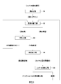
- FIG. 1 is a process diagram of a method for hydrometallizing nickel oxide ore.
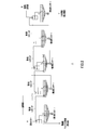
- FIG. 2 is a configuration diagram of a processing apparatus that performs the CCD method by connecting thickeners in multiple stages.
- FIG. 3 is a configuration diagram of a thickener (only one stage).
- the solid-liquid separation treatment method according to the present embodiment is a solid-liquid separation treatment that separates solids such as precipitates contained in the slurry from the slurry to obtain a solution that constitutes the supernatant from which the solid-liquid components have been removed. It is a method. More specifically, as a solid-liquid separator, a sedimentation separation tank having an overflow part for discharging a supernatant liquid at a peripheral part thereof, a cylindrical feed well arranged perpendicularly to the center part thereof, and a stirring tank This is a solid-liquid separation treatment method in which the thickener is provided in multiple stages, and the solid content is separated and removed while the slurry to be treated is washed in multiple stages.
- a predetermined proportion of the flocculant among the predetermined amount of flocculant is added to the first stage. Add to the feed well in the thickener and add the remaining flocculant to the overflow in the second stage thickener.
- the solid-liquid separation treatment method according to the present embodiment is characterized by the method of adding the flocculant added during the solid-liquid separation.
- this solid-liquid separation processing method even when the number of thickener stages used for multi-stage washing is set to a smaller number, it is possible to obtain a solution (supernatant liquid) with high transparency (clarity) as before. it can.
- the installation space for the solid-liquid separation device can be reduced, and the initial capital investment can be greatly reduced, so that efficient solid-liquid separation processing can be performed.
- the slurry to which the solid-liquid separation treatment method according to the present embodiment can be applied is not particularly limited.
- a leaching slurry obtained by leaching can be used in a nickel oxide ore wet smelting method.
- the leaching residue in the leaching slurry can be separated and the leaching liquid having high transparency can be obtained with a smaller number of stages than before.
- the example which used the leaching slurry obtained by performing the leaching process with respect to nickel oxide ore as a slurry is demonstrated more concretely as a specific example.
- Nickel oxide ore hydrometallurgical process ⁇ 2.
- Nickel oxide ore hydrometallurgical process ⁇ 2.
- This nickel oxide ore wet smelting method is a hydrometallurgical method of leaching and recovering nickel and cobalt from nickel oxide ore using, for example, a high-pressure acid leaching method (HPAL method).
- HPAL method high-pressure acid leaching method
- FIG. 1 shows an example of a process diagram of a hydrometallurgical method using high pressure acid leaching of nickel oxide ore.
- a leach step S1 in which sulfuric acid is added to a slurry of nickel oxide ore and a leaching process is performed under high temperature and high pressure, and the residue is removed while washing the leach slurry in multiple stages.
- Solid-liquid separation step S2 to obtain a leachate containing impurity elements together with nickel and cobalt, and adjusting the pH of the leachate to separate neutralized starch containing impurity elements and neutralizing containing zinc together with nickel and cobalt
- Neutralization step S3 for obtaining a final solution, and a zinc sulfide is generated by adding a sulfurizing agent such as hydrogen sulfide gas to the neutralized final solution, and the zinc sulfide is separated and removed to recover nickel containing nickel and cobalt.
- Leaching step S1 a leaching process using, for example, a high-pressure acid leaching method is performed on the nickel oxide ore. Specifically, sulfuric acid is added to an ore slurry obtained by pulverizing nickel oxide ore as a raw material, and heated under a high temperature condition of 220 to 280 ° C. using, for example, a high-temperature pressure vessel (autoclave). The ore slurry is agitated by pressing to form a leaching slurry composed of the leaching solution and the leaching residue.
- a high-pressure acid leaching method is performed on the nickel oxide ore. Specifically, sulfuric acid is added to an ore slurry obtained by pulverizing nickel oxide ore as a raw material, and heated under a high temperature condition of 220 to 280 ° C. using, for example, a high-temperature pressure vessel (autoclave). The ore slurry is agitated by pressing to form a leaching slurry composed of the leaching solution and the leaching residue.
- the nickel oxide ore used in the leaching step S1 is mainly so-called laterite ore such as limonite or saprolite ore.
- Laterite ore usually has a nickel content of 0.8 to 2.5% by weight and is contained as a hydroxide or siliceous clay (magnesium silicate) mineral.
- the iron content is 10 to 50% by weight and is mainly in the form of trivalent hydroxide (goethite), but partly divalent iron is contained in the siliceous clay.
- an oxidized ore containing valuable metals such as nickel, cobalt, manganese, and copper, for example, a manganese nodule that exists in the deep sea bottom is used.
- the leaching process in the leaching step S1 a leaching reaction and a high-temperature thermal hydrolysis reaction occur, and leaching as a sulfate such as nickel or cobalt and immobilization of the leached iron sulfate as hematite are performed.
- the immobilization of iron ions does not proceed completely, the leaching slurry obtained usually contains divalent and trivalent iron ions in addition to nickel, cobalt and the like.
- the amount of sulfuric acid added in the leaching step S1 is not particularly limited, and an excessive amount that allows iron in the ore to be leached is used. For example, 300 to 400 kg per ton of ore. If the amount of sulfuric acid added per ton of ore exceeds 400 kg, the sulfuric acid cost increases, which is not preferable.
- the pH of the obtained leachate is adjusted to 0.1 to 1.0 from the viewpoint of filterability of the leaching residue containing hematite produced in the next solid-liquid separation step S2. It is preferable to do.
- the leaching slurry is mixed with the cleaning liquid, and then a thickener is provided in multiple stages as a solid-liquid separation device to perform a solid-liquid separation process.
- the leaching slurry is first diluted with a cleaning liquid, and then the leaching residue in the slurry is concentrated as a thickener sediment.
- the nickel content adhering to the leaching residue can be reduced according to the degree of dilution.
- the recovery rate of nickel and cobalt can be improved by connecting the thickeners in multiple stages.
- a continuous countercurrent cleaning method (CCD method: Counter-Current Decantation) in which a countercurrent is brought into contact with a cleaning liquid not containing nickel is used.
- CCD method Counter-Current Decantation
- the cleaning liquid newly introduced into the system can be reduced, and the recovery rate of nickel and cobalt can be 95% or more.
- the cleaning liquid is not particularly limited, but a cleaning liquid that does not contain nickel and does not affect the process can be used. Among them, it is preferable to use an aqueous solution having a pH of 1 to 3. If the pH of the cleaning liquid is high, a bulky aluminum hydroxide is produced when aluminum is contained in the leachate, which causes poor settling of the leach residue in the thickener. For this reason, it is preferable to repeatedly use a low pH (pH of about 1 to 3) poor solution obtained in the nickel recovery step S5, which is a subsequent step, as the cleaning solution.
- the pH of the resulting neutralized final solution is 4 or less, preferably 3.0 to 3.5, more preferably 3.1 to 3, while suppressing the oxidation of the separated leachate.
- the neutralization step S3 by performing the neutralization treatment on the leachate in this way, the excess acid used in the leaching treatment by the high-pressure acid leaching method is neutralized, and the neutralization finish that becomes the base of the mother liquor for nickel recovery is obtained. Impurities such as trivalent iron ions and aluminum ions remaining in the solution are removed as neutralized starch.
- step S4 zinc sulfide is generated by adding a sulfiding agent such as hydrogen sulfide gas to the final neutralized solution obtained from the neutralizing step S3 and subjecting it to a sulfiding treatment.
- the zinc sulfide is separated and removed to obtain a nickel recovery mother liquor (dezincing final solution) containing nickel and cobalt.
- zinc is selected with respect to nickel and cobalt by introducing a neutralized final solution containing zinc together with nickel and cobalt into a pressurized container and blowing hydrogen sulfide gas into the gas phase. Sulfurically produces zinc sulfide and nickel recovery mother liquor. 2 shows an example in which hydrogen sulfide gas is used as a sulfiding agent.
- Nickel recovery step S5 a sulfiding agent such as hydrogen sulfide gas is blown into the nickel recovery mother liquor obtained by separating and removing zinc, which is an impurity element, as zinc sulfide in the dezincification step S4. A sulfurization reaction is caused to generate a sulfide containing nickel and cobalt (a nickel cobalt mixed sulfide) and a poor liquid.
- a sulfiding agent such as hydrogen sulfide gas is blown into the nickel recovery mother liquor obtained by separating and removing zinc, which is an impurity element, as zinc sulfide in the dezincification step S4.
- a sulfurization reaction is caused to generate a sulfide containing nickel and cobalt (a nickel cobalt mixed sulfide) and a poor liquid.
- the nickel recovery mother liquor is a sulfuric acid solution in which impurity components are reduced from the leachate of nickel oxide ore through the neutralization step S3 and the dezincification step S4.
- the pH is 3.2 to 4.0 and the nickel concentration is The solution is 2 to 5 g / L and the cobalt concentration is 0.1 to 1.0 g / L.
- the nickel recovery mother liquor may contain several g / L of iron, magnesium, manganese, etc. as impurity components. These impurity components are sulfides with respect to nickel and cobalt to be recovered. As a result, the resulting sulfide is not contained.
- the nickel recovery step S5 a nickel / cobalt mixed sulfide with a small amount of impurity components and a poor liquid in which the nickel concentration is stabilized at a low level are generated and recovered.
- the nickel / cobalt mixed sulfide slurry obtained by the sulfidation reaction is subjected to a sedimentation separation process using a sedimentation separator such as a thickener, so that the nickel / cobalt mixed sulfide as a precipitate is removed from the thickener. Separate and collect from the bottom.
- the aqueous solution component overflows and is recovered as a poor solution.
- the poor solution contains impurity elements such as iron, magnesium, and manganese that are contained without being sulfided.
- FIG. 2 is a block diagram showing an example of a processing apparatus that performs the CCD method by connecting thickeners in multiple stages.
- the processing apparatus 1 shown in FIG. 2 shows a configuration example in which five stages of thickeners are connected, the number of connecting stages is not limited to this.
- a thickener consisting of a combination of a sedimentation separation tank in which solid-liquid separation processing is performed and a stirring tank is used as one stage, and a processing apparatus in which the thickener is connected in series, for example, 5 to 8 stages is used.
- the first stage thickener at one end (A side in FIG. 2) is charged with the leaching slurry obtained in the leaching step S1, and the final stage at the other end (B side in FIG. 2).
- a cleaning liquid such as industrial water is charged in the thickener of the eye (fifth stage).
- the leaching slurry and the cleaning liquid come into contact with each other in the processing apparatus 1 in countercurrent, and at the same time, a flocculant is added to the leaching slurry charged from the end A, thereby aggregating the solid content in the slurry and solidifying it. Promote liquid separation.
- FIG. 3 shows a block diagram of a thickener (only one stage) constituting each stage of the processing apparatus 1 shown in FIG.
- the processing apparatus 1 includes a plurality of thickeners connected in multiple stages, and the thickener 10 includes the stirring tank 11 and the sedimentation separation tank 12.
- the stirring tank 11 is a tank provided with stirring members such as a stirring shaft and stirring blades inside.
- the leaching slurry and the overflow liquid fed from the subsequent thickener are respectively charged and agitated and mixed.
- the thickener agitation tank 11 in the final stage (the fifth stage in the example of FIG. 2) is charged with fresh wash water instead of the overflow liquid.
- the leaching slurry and the overflow liquid are agitated and mixed, whereby the leaching slurry is washed and the adhering water adhering to the solid content is washed away.
- the sedimentation / separation tank 12 is, for example, a cylindrical treatment tank, and a leaching slurry is charged therein, and the solid content in the leaching slurry is settled and separated.
- the sedimentation / separation tank 12 is provided with a cylindrical feed well 13 disposed vertically inside thereof.
- the feed well 13 is provided substantially concentrically with the sedimentation tank 12.
- the feed well 13 serves as a feed path for feeding (feeding) the leaching slurry supplied from the stirring tank 11 into the sedimentation separation tank 12.
- the sedimentation tank 12 has an overflow part 14 for overflowing (OF) and discharging the leachate, which is a supernatant obtained by sedimentation and separation of the solid content in the leach slurry, at the periphery of the tank upper part.
- the overflow portion 14 has, for example, a bowl-like shape, and is connected to a flow path for feeding the overflow liquid from the subsequent thickener to the stirring tank 11.
- the overflowed solution (hereinafter, also referred to as overflow liquid) is flowed to the preceding stirring tank 11 as described above, while the slurry containing other solids is The liquid is taken out from the lower part of the settling tank 12 and pumped to the agitation tank 11 at the subsequent stage by the pump 15.
- FIG. 3 shows the basic flow when the leach slurry is washed in multiple stages by the processing apparatus 1 (FIG. 2) in which a plurality of thickeners composed of the stirring tank 11 and the sedimentation separation tank 12 are connected. Will be explained.
- the arrow in FIG. 2 shows the flow of leaching slurry or overflow liquid.
- the leaching slurry obtained in the leaching step S1 and the overflow liquid from the second stage thickener sedimentation separation tank are charged into the stirring tank, They are stirred and mixed.
- the adhering water adhering to the solid content in the leaching slurry is washed by the overflow liquid, and then the leaching slurry washed from the stirring tank through the feed well is charged into the sedimentation separation tank. .
- a flocculant for aggregating the solid content in the slurry is added together with the leach slurry through the feed well. Then, the leaching slurry and the flocculant are mixed in the settling tank, and the solid content in the slurry is coagulated and separated. The slurry containing the separated solid content is extracted from the lower part of the sedimentation separation tank and transferred to the second-stage thickener stirring tank of the second stage through a pump. On the other hand, the supernatant liquid overflowed from the sedimentation tank through the overflow portion is supplied to the neutralization step S3 of the next step in the hydrometallurgical method.
- the solid content extracted from the lower part of the sedimentation tank of the first stage thickener in the first stage is charged into the stirring tank, and the third stage in the second stage.
- the overflow liquid from the sedimentation tank of the eye thickener is charged, and the water adhering to the solid content is washed away by the overflow liquid.
- cleaning in a stirring tank is inserted in a sedimentation separation tank through a feed well, and solid content in a slurry is coagulated and separated, and is isolate
- the separated slurry containing the solid content is extracted from the lower part of the sedimentation separation tank, and transferred to the third-stage thickener stirring tank at the subsequent stage via a pump.
- the overflow liquid overflowing from the settling tank through the overflow section is charged into the stirring tank via a pipe connected to the stirring tank of the first stage thickener in the previous stage. .
- the slurry containing the solid content is contacted with the overflow liquid in countercurrent by the same procedure, so that the multistage cleaning is performed.
- the overflow liquid from the thickener at the final stage is the smallest as the content of valuable metals such as nickel and cobalt.
- valuable metals have already been washed in the agitation tank of the thickener in the previous stage (third stage in FIG. 2).
- Another reason is that the slurry stirred and washed is charged into the final thickener.
- the overflow liquid from the last stage (the fourth stage in FIG. 2) has a larger amount of valuable metals in the adhering water adhering to the solid content than the last stage, and as it gradually moves away from the last stage, The valuable metal content increases, and the overflow metal from the first stage thickener maximizes the valuable metal content.
- operation is performed to recover a crude nickel sulfate aqueous solution that is an overflow liquid with a nickel and cobalt recovery rate of 95% or more.
- the overflow liquid from the first stage thickener is subjected to solid-liquid separation in each stage thickener, and the precipitation of fine particles is also progressing. Therefore, the overflow liquid from the first stage thickener has the lowest turbidity (highest transparency). Specifically, the turbidity is 200 NTU or less.
- the recovery rate of nickel and cobalt recovered based on the overflowed crude nickel sulfate aqueous solution (leachate) has a good correlation with the turbidity of the leachate, and the turbidity is 200 NTU or less. By operating in such a manner, the recovery rate of nickel and cobalt becomes 95% or more.
- the recovery rate of nickel and cobalt is 95% or more even with a treatment device having a smaller number of connection stages of thickeners. It is desirable to do so.
- the above-described thickener is provided in multiple stages, and in the process of separating solids while washing the leach slurry in multiple stages, aggregation for aggregating the solids in the leach slurry
- a predetermined amount of the flocculant is added separately for the first-stage thickener and the second-stage thickener. Specifically, as shown in FIG. 2, out of a predetermined amount of flocculant, a predetermined proportion of flocculant is added to the feed well of the first-stage thickener, and the remaining flocculant is added to the second-stage flocculant. Add to the overflow part of the thickener.
- the solid content in the leach slurry is more effectively agglomerated, and even if the number of thickener stages is small, the overflow finally discharged from the first stage thickener.
- the turbidity of a liquid can be made low and the crude nickel sulfate aqueous solution from which the recovery rate of nickel and cobalt will be 95% or more can be obtained.
- the same effects as those of the prior art can be obtained sufficiently.
- the installation space for the solid-liquid separation device can be reduced, and the initial capital investment can be greatly reduced, so that efficient solid-liquid separation processing can be performed.
- the action mechanism of such a solid-liquid separation treatment method is considered as follows. That is, in this solid-liquid separation processing method, even if the addition amount (total amount) of the flocculant is the same (a certain amount), a part of the flocculant is added to the overflow portion of the second stage thickener. As a result, the total amount is added to the feed well of the first stage thickener in a state where the concentration of the flocculant is reduced compared to the case where the total amount is added only to the first stage. Then, the flocculant is not added as a lump to the first stage thickener, but is added to the first stage thickener and the second stage thickener. The flocculant can be efficiently contacted with the solid content. As a result, solid-liquid separation proceeds more effectively, and it is considered that the turbidity of the overflow liquid from the first stage thickener can be effectively reduced.
- the total addition amount of the flocculant is not particularly limited, and can be appropriately set according to the solid content contained in the leaching slurry to be treated.
- the ratio of the amount of flocculant added that is, the ratio of the amount of flocculant added to the first stage thickener and the amount of flocculant added to the second stage thickener (first stage: second stage).
- the ratio of the addition amount of the flocculant is outside the above range, the effect of lowering the turbidity of the overflow liquid is not sufficiently exhibited, and the recovery rate of nickel from the finally obtained crude nickel sulfate aqueous solution is 95%. There is a possibility of becoming less than. That is, the turbidity of the crude nickel sulfate aqueous solution may become larger than 200 NTU.
- Example 1 In the solid-liquid separation step of the nickel oxide ore hydrometallurgy method, the leaching slurry obtained in the leaching step is subjected to multi-stage cleaning (CCD method) by connecting thickeners in multiple stages as shown in FIG. However, the solid-liquid separation process which isolate
- first-stage: second-stage ratio The ratio of the amount of flocculant added to the first-stage thickener and the amount of flocculant added to the second-stage thickener (hereinafter referred to as “first-stage: second-stage ratio”) is as follows. It added so that it might be set to 90:10.
- Example 2 In Example 2, the solid-liquid separation process was performed in the same manner as in Example 1 except that the ratio of the first stage: second stage was 50:50.
- Example 3 In Example 3, the solid-liquid separation process was performed in the same manner as in Example 1 except that the ratio of the first stage: second stage was 95: 5.
- Comparative Example 1 In Comparative Example 1, the solid-liquid separation process was performed in the same manner as in Example 1 except that the ratio of the first stage to the second stage was 97: 3.
- Comparative Example 2 In Comparative Example 2, the solid-liquid separation process was performed in the same manner as in Example 1 except that the ratio of the first stage to the second stage was 45:65.
- Table 1 summarizes the results of the solid-liquid separation process in each example and comparative example.
- turbidity of the crude nickel sulfate aqueous solution obtained from the CCD process refers to the roughness that overflowed from the overflow of the first stage thickener at the time when 8 hours had passed since the stable operation was reached. It is a measured value of turbidity about nickel sulfate aqueous solution. The turbidity was measured using a 2100P type scattered light turbidimeter manufactured by HACH.
Landscapes
- Chemical & Material Sciences (AREA)
- Engineering & Computer Science (AREA)
- Chemical Kinetics & Catalysis (AREA)
- Mechanical Engineering (AREA)
- Manufacturing & Machinery (AREA)
- Materials Engineering (AREA)
- Metallurgy (AREA)
- Organic Chemistry (AREA)
- Geology (AREA)
- Geochemistry & Mineralogy (AREA)
- General Life Sciences & Earth Sciences (AREA)
- Life Sciences & Earth Sciences (AREA)
- Environmental & Geological Engineering (AREA)
- Inorganic Chemistry (AREA)
- Manufacture And Refinement Of Metals (AREA)
Priority Applications (6)
| Application Number | Priority Date | Filing Date | Title |
|---|---|---|---|
| CN201380071086.0A CN104994925B (zh) | 2013-01-21 | 2013-12-10 | 固液分离处理方法、以及氧化镍矿石的湿式冶炼方法 |
| CA2898707A CA2898707A1 (en) | 2013-01-21 | 2013-12-10 | Solid-liquid-separation processing method, and hydrometallurgical method for nickel oxide ore |
| US14/761,893 US20150337411A1 (en) | 2013-01-21 | 2013-12-10 | Solid-liquid-separation processing method, and hydrometallurgical method for nickel oxide ore |
| AU2013374645A AU2013374645B2 (en) | 2013-01-21 | 2013-12-10 | Solid-liquid-separation processing method, and hydrometallurgical method for nickel oxide ore |
| EP13871448.0A EP2957332B1 (en) | 2013-01-21 | 2013-12-10 | Solid-liquid-separation processing method, and hydrometallurgical method for nickel oxide ore |
| PH12015501597A PH12015501597A1 (en) | 2013-01-21 | 2015-07-20 | Solid-liquid-separation processing method, and hydrometallurgical method for nickel oxide ore |
Applications Claiming Priority (2)
| Application Number | Priority Date | Filing Date | Title |
|---|---|---|---|
| JP2013008659A JP5644878B2 (ja) | 2013-01-21 | 2013-01-21 | 固液分離処理方法、並びにニッケル酸化鉱石の湿式製錬方法 |
| JP2013-008659 | 2013-01-21 |
Publications (1)
| Publication Number | Publication Date |
|---|---|
| WO2014112248A1 true WO2014112248A1 (ja) | 2014-07-24 |
Family
ID=51209358
Family Applications (1)
| Application Number | Title | Priority Date | Filing Date |
|---|---|---|---|
| PCT/JP2013/083090 Ceased WO2014112248A1 (ja) | 2013-01-21 | 2013-12-10 | 固液分離処理方法、並びにニッケル酸化鉱石の湿式製錬方法 |
Country Status (8)
| Country | Link |
|---|---|
| US (1) | US20150337411A1 (enExample) |
| EP (1) | EP2957332B1 (enExample) |
| JP (1) | JP5644878B2 (enExample) |
| CN (1) | CN104994925B (enExample) |
| AU (1) | AU2013374645B2 (enExample) |
| CA (1) | CA2898707A1 (enExample) |
| PH (1) | PH12015501597A1 (enExample) |
| WO (1) | WO2014112248A1 (enExample) |
Cited By (2)
| Publication number | Priority date | Publication date | Assignee | Title |
|---|---|---|---|---|
| JP2017144418A (ja) * | 2016-02-18 | 2017-08-24 | 住友金属鉱山株式会社 | 高濃度スラリーを得るためのシックナー及びその管理方法 |
| JP7585804B2 (ja) | 2021-01-21 | 2024-11-19 | 住友金属鉱山株式会社 | 固液分離処理方法、ニッケル酸化鉱石の湿式製錬方法 |
Families Citing this family (7)
| Publication number | Priority date | Publication date | Assignee | Title |
|---|---|---|---|---|
| EP3128018A4 (en) * | 2014-12-05 | 2017-04-26 | Sumitomo Metal Mining Co., Ltd. | Apparatus for producing ore slurry and process for producing ore slurry |
| JP6583158B2 (ja) * | 2015-09-15 | 2019-10-02 | 住友金属鉱山株式会社 | 蛍光x線分析用試料調製方法 |
| JP7005909B2 (ja) * | 2016-05-02 | 2022-01-24 | 住友金属鉱山株式会社 | 中和処理方法、及び中和終液の濁度低減方法 |
| JP6984191B2 (ja) * | 2017-06-20 | 2021-12-17 | 住友金属鉱山株式会社 | ニッケル高圧浸出残渣の固液分離方法 |
| JP7091909B2 (ja) * | 2018-07-20 | 2022-06-28 | 住友金属鉱山株式会社 | ニッケル粉の製造方法 |
| JP7115170B2 (ja) * | 2018-09-12 | 2022-08-09 | 住友金属鉱山株式会社 | ニッケル酸化鉱石の処理方法及び該処理方法を含んだニッケルコバルト混合硫化物の製造方法 |
| CN112169381A (zh) * | 2020-10-15 | 2021-01-05 | 圣奥化学科技有限公司 | 一种固液分离洗涤装置及其用途 |
Citations (8)
| Publication number | Priority date | Publication date | Assignee | Title |
|---|---|---|---|---|
| JPH05229816A (ja) * | 1991-12-27 | 1993-09-07 | Nippon Light Metal Co Ltd | 赤泥の沈降分離における赤泥沈降助剤の添加方法 |
| JPH11221575A (ja) * | 1998-02-04 | 1999-08-17 | Japan Organo Co Ltd | 重金属イオン含有排水の処理方法 |
| JP2001239272A (ja) * | 2000-03-02 | 2001-09-04 | Sumitomo Heavy Ind Ltd | 銀含有排水の処理方法及び処理装置 |
| JP2001286875A (ja) * | 2000-04-07 | 2001-10-16 | Mitsubishi Materials Corp | 含ヒ素排水の処理方法 |
| JP2005350766A (ja) | 2004-05-13 | 2005-12-22 | Sumitomo Metal Mining Co Ltd | ニッケル酸化鉱石の湿式製錬方法 |
| JP2011225956A (ja) | 2010-04-22 | 2011-11-10 | Sumitomo Metal Mining Co Ltd | 貯液装置及びその圧力制御方法 |
| JP2011225908A (ja) | 2010-04-15 | 2011-11-10 | Sumitomo Metal Mining Co Ltd | ニッケル酸化鉱石の湿式精錬プラント及びその操業方法 |
| JP2012148265A (ja) * | 2010-12-27 | 2012-08-09 | Mitsubishi Materials Corp | フッ化カルシウムの回収方法および回収装置 |
Family Cites Families (8)
| Publication number | Priority date | Publication date | Assignee | Title |
|---|---|---|---|---|
| US4110401A (en) * | 1977-07-11 | 1978-08-29 | Amax Inc. | Solid-liquid separation of laterite slurries |
| US4274958A (en) * | 1978-10-10 | 1981-06-23 | Dorr-Oliver Incorporated | Flocculant distributor means for feedwell |
| FR2767143A1 (fr) * | 1997-08-06 | 1999-02-12 | Le Nickel Sln | Procede pour diminuer la quantite d'eau contenue dans les pulpes de minerais nickeliferes oxydes |
| EP1731622B1 (en) * | 2004-03-31 | 2010-07-28 | Pacific Metals Co., Ltd. | Leach method for recovering nickel or cobalt |
| CN1978079A (zh) * | 2005-11-29 | 2007-06-13 | 吕宪俊 | 一种全尾矿浓缩胶结新工艺 |
| CN2907906Y (zh) * | 2006-05-24 | 2007-06-06 | 威海市海王旋流器有限公司 | 旋流澄清器 |
| JP5157943B2 (ja) * | 2009-02-04 | 2013-03-06 | 住友金属鉱山株式会社 | 硫酸酸性水溶液からのニッケル回収方法 |
| US20130008856A1 (en) * | 2011-07-06 | 2013-01-10 | Cognis Ip Management Gmbh | Method For Controlling Solids/Liquid Decant Unit Operations And Systems |
-
2013
- 2013-01-21 JP JP2013008659A patent/JP5644878B2/ja not_active Expired - Fee Related
- 2013-12-10 CA CA2898707A patent/CA2898707A1/en not_active Abandoned
- 2013-12-10 AU AU2013374645A patent/AU2013374645B2/en not_active Ceased
- 2013-12-10 CN CN201380071086.0A patent/CN104994925B/zh not_active Expired - Fee Related
- 2013-12-10 US US14/761,893 patent/US20150337411A1/en not_active Abandoned
- 2013-12-10 EP EP13871448.0A patent/EP2957332B1/en not_active Not-in-force
- 2013-12-10 WO PCT/JP2013/083090 patent/WO2014112248A1/ja not_active Ceased
-
2015
- 2015-07-20 PH PH12015501597A patent/PH12015501597A1/en unknown
Patent Citations (8)
| Publication number | Priority date | Publication date | Assignee | Title |
|---|---|---|---|---|
| JPH05229816A (ja) * | 1991-12-27 | 1993-09-07 | Nippon Light Metal Co Ltd | 赤泥の沈降分離における赤泥沈降助剤の添加方法 |
| JPH11221575A (ja) * | 1998-02-04 | 1999-08-17 | Japan Organo Co Ltd | 重金属イオン含有排水の処理方法 |
| JP2001239272A (ja) * | 2000-03-02 | 2001-09-04 | Sumitomo Heavy Ind Ltd | 銀含有排水の処理方法及び処理装置 |
| JP2001286875A (ja) * | 2000-04-07 | 2001-10-16 | Mitsubishi Materials Corp | 含ヒ素排水の処理方法 |
| JP2005350766A (ja) | 2004-05-13 | 2005-12-22 | Sumitomo Metal Mining Co Ltd | ニッケル酸化鉱石の湿式製錬方法 |
| JP2011225908A (ja) | 2010-04-15 | 2011-11-10 | Sumitomo Metal Mining Co Ltd | ニッケル酸化鉱石の湿式精錬プラント及びその操業方法 |
| JP2011225956A (ja) | 2010-04-22 | 2011-11-10 | Sumitomo Metal Mining Co Ltd | 貯液装置及びその圧力制御方法 |
| JP2012148265A (ja) * | 2010-12-27 | 2012-08-09 | Mitsubishi Materials Corp | フッ化カルシウムの回収方法および回収装置 |
Non-Patent Citations (1)
| Title |
|---|
| See also references of EP2957332A4 |
Cited By (4)
| Publication number | Priority date | Publication date | Assignee | Title |
|---|---|---|---|---|
| JP2017144418A (ja) * | 2016-02-18 | 2017-08-24 | 住友金属鉱山株式会社 | 高濃度スラリーを得るためのシックナー及びその管理方法 |
| WO2017142081A1 (ja) * | 2016-02-18 | 2017-08-24 | 住友金属鉱山株式会社 | 高濃度スラリーを得るためのシックナー及びその管理方法 |
| AU2017219939B2 (en) * | 2016-02-18 | 2019-10-31 | Sumitomo Metal Mining Co., Ltd. | Thickener for obtaining high concentration slurry and control method for same |
| JP7585804B2 (ja) | 2021-01-21 | 2024-11-19 | 住友金属鉱山株式会社 | 固液分離処理方法、ニッケル酸化鉱石の湿式製錬方法 |
Also Published As
| Publication number | Publication date |
|---|---|
| CA2898707A1 (en) | 2014-07-24 |
| PH12015501597B1 (en) | 2015-10-19 |
| EP2957332A4 (en) | 2016-11-02 |
| JP5644878B2 (ja) | 2014-12-24 |
| JP2014138918A (ja) | 2014-07-31 |
| CN104994925B (zh) | 2017-03-08 |
| EP2957332A1 (en) | 2015-12-23 |
| US20150337411A1 (en) | 2015-11-26 |
| CN104994925A (zh) | 2015-10-21 |
| AU2013374645A1 (en) | 2015-09-10 |
| EP2957332B1 (en) | 2018-12-05 |
| PH12015501597A1 (en) | 2015-10-19 |
| AU2013374645A2 (en) | 2015-09-24 |
| AU2013374645B2 (en) | 2018-05-10 |
Similar Documents
| Publication | Publication Date | Title |
|---|---|---|
| JP5644878B2 (ja) | 固液分離処理方法、並びにニッケル酸化鉱石の湿式製錬方法 | |
| JP5692458B1 (ja) | 固液分離処理方法、並びにニッケル酸化鉱石の湿式製錬方法 | |
| JP7095606B2 (ja) | 湿式製錬法によるニッケル酸化鉱石からのニッケルコバルト混合硫化物の製造方法 | |
| WO2013150642A1 (ja) | クロマイト回収方法、並びにニッケル酸化鉱石の湿式製錬方法 | |
| JP6984191B2 (ja) | ニッケル高圧浸出残渣の固液分離方法 | |
| JP7183503B2 (ja) | 高濃度鉱石スラリーの製造方法 | |
| CN107250394B (zh) | 镍氧化物矿石的湿式冶炼方法 | |
| JP6750698B2 (ja) | ニッケル高圧浸出残渣の固液分離方法 | |
| JP5790839B2 (ja) | クロマイト回収方法 | |
| JP7279578B2 (ja) | シックナーによる固液分離方法及びこれを含んだニッケル酸化鉱石の湿式製錬方法 | |
| JP6996328B2 (ja) | 脱亜鉛処理方法、ニッケル酸化鉱石の湿式製錬方法 | |
| JP7005909B2 (ja) | 中和処理方法、及び中和終液の濁度低減方法 | |
| WO2014080665A1 (ja) | 中和スラリーの沈降分離方法、並びにニッケル酸化鉱石の湿式製錬方法 | |
| JP6256491B2 (ja) | スカンジウムの回収方法 | |
| JP7039936B2 (ja) | ニッケル高圧浸出残渣の固液分離方法 | |
| JP7585804B2 (ja) | 固液分離処理方法、ニッケル酸化鉱石の湿式製錬方法 | |
| JP2019157236A (ja) | 固液分離処理方法、ニッケル酸化鉱石の湿式製錬方法 | |
| JP2019077928A (ja) | 中和処理方法およびニッケル酸化鉱石の湿式製錬方法 | |
| JP7147362B2 (ja) | ニッケル酸化鉱石の湿式製錬法における臭気低減方法 | |
| JP6888359B2 (ja) | 金属酸化鉱の製錬方法 | |
| JP7585921B2 (ja) | ニッケル酸化鉱石の湿式製錬方法 | |
| JP7508977B2 (ja) | 脱亜鉛処理方法、ニッケル酸化鉱石の湿式製錬方法 | |
| JP2019049020A (ja) | ニッケル酸化鉱石の湿式製錬方法 |
Legal Events
| Date | Code | Title | Description |
|---|---|---|---|
| 121 | Ep: the epo has been informed by wipo that ep was designated in this application |
Ref document number: 13871448 Country of ref document: EP Kind code of ref document: A1 |
|
| WWE | Wipo information: entry into national phase |
Ref document number: 14761893 Country of ref document: US |
|
| ENP | Entry into the national phase |
Ref document number: 2898707 Country of ref document: CA |
|
| NENP | Non-entry into the national phase |
Ref country code: DE |
|
| WWE | Wipo information: entry into national phase |
Ref document number: IDP00201505105 Country of ref document: ID |
|
| WWE | Wipo information: entry into national phase |
Ref document number: 2013871448 Country of ref document: EP |
|
| ENP | Entry into the national phase |
Ref document number: 2013374645 Country of ref document: AU Date of ref document: 20131210 Kind code of ref document: A |