WO2014097981A1 - Fmcwレーダ装置 - Google Patents
Fmcwレーダ装置 Download PDFInfo
- Publication number
- WO2014097981A1 WO2014097981A1 PCT/JP2013/083444 JP2013083444W WO2014097981A1 WO 2014097981 A1 WO2014097981 A1 WO 2014097981A1 JP 2013083444 W JP2013083444 W JP 2013083444W WO 2014097981 A1 WO2014097981 A1 WO 2014097981A1
- Authority
- WO
- WIPO (PCT)
- Prior art keywords
- peak
- frequency
- oscillation
- unit
- target
- Prior art date
- Legal status (The legal status is an assumption and is not a legal conclusion. Google has not performed a legal analysis and makes no representation as to the accuracy of the status listed.)
- Ceased
Links
Images



Classifications
-
- G—PHYSICS
- G01—MEASURING; TESTING
- G01S—RADIO DIRECTION-FINDING; RADIO NAVIGATION; DETERMINING DISTANCE OR VELOCITY BY USE OF RADIO WAVES; LOCATING OR PRESENCE-DETECTING BY USE OF THE REFLECTION OR RERADIATION OF RADIO WAVES; ANALOGOUS ARRANGEMENTS USING OTHER WAVES
- G01S13/00—Systems using the reflection or reradiation of radio waves, e.g. radar systems; Analogous systems using reflection or reradiation of waves whose nature or wavelength is irrelevant or unspecified
- G01S13/02—Systems using reflection of radio waves, e.g. primary radar systems; Analogous systems
- G01S13/06—Systems determining position data of a target
- G01S13/08—Systems for measuring distance only
- G01S13/32—Systems for measuring distance only using transmission of continuous waves, whether amplitude-, frequency-, or phase-modulated, or unmodulated
- G01S13/34—Systems for measuring distance only using transmission of continuous waves, whether amplitude-, frequency-, or phase-modulated, or unmodulated using transmission of continuous, frequency-modulated waves while heterodyning the received signal, or a signal derived therefrom, with a locally-generated signal related to the contemporaneously transmitted signal
- G01S13/345—Systems for measuring distance only using transmission of continuous waves, whether amplitude-, frequency-, or phase-modulated, or unmodulated using transmission of continuous, frequency-modulated waves while heterodyning the received signal, or a signal derived therefrom, with a locally-generated signal related to the contemporaneously transmitted signal using triangular modulation
-
- G—PHYSICS
- G01—MEASURING; TESTING
- G01S—RADIO DIRECTION-FINDING; RADIO NAVIGATION; DETERMINING DISTANCE OR VELOCITY BY USE OF RADIO WAVES; LOCATING OR PRESENCE-DETECTING BY USE OF THE REFLECTION OR RERADIATION OF RADIO WAVES; ANALOGOUS ARRANGEMENTS USING OTHER WAVES
- G01S13/00—Systems using the reflection or reradiation of radio waves, e.g. radar systems; Analogous systems using reflection or reradiation of waves whose nature or wavelength is irrelevant or unspecified
- G01S13/02—Systems using reflection of radio waves, e.g. primary radar systems; Analogous systems
- G01S13/06—Systems determining position data of a target
- G01S13/08—Systems for measuring distance only
- G01S13/32—Systems for measuring distance only using transmission of continuous waves, whether amplitude-, frequency-, or phase-modulated, or unmodulated
- G01S13/34—Systems for measuring distance only using transmission of continuous waves, whether amplitude-, frequency-, or phase-modulated, or unmodulated using transmission of continuous, frequency-modulated waves while heterodyning the received signal, or a signal derived therefrom, with a locally-generated signal related to the contemporaneously transmitted signal
- G01S13/343—Systems for measuring distance only using transmission of continuous waves, whether amplitude-, frequency-, or phase-modulated, or unmodulated using transmission of continuous, frequency-modulated waves while heterodyning the received signal, or a signal derived therefrom, with a locally-generated signal related to the contemporaneously transmitted signal using sawtooth modulation
-
- G—PHYSICS
- G01—MEASURING; TESTING
- G01S—RADIO DIRECTION-FINDING; RADIO NAVIGATION; DETERMINING DISTANCE OR VELOCITY BY USE OF RADIO WAVES; LOCATING OR PRESENCE-DETECTING BY USE OF THE REFLECTION OR RERADIATION OF RADIO WAVES; ANALOGOUS ARRANGEMENTS USING OTHER WAVES
- G01S13/00—Systems using the reflection or reradiation of radio waves, e.g. radar systems; Analogous systems using reflection or reradiation of waves whose nature or wavelength is irrelevant or unspecified
- G01S13/88—Radar or analogous systems specially adapted for specific applications
- G01S13/93—Radar or analogous systems specially adapted for specific applications for anti-collision purposes
- G01S13/931—Radar or analogous systems specially adapted for specific applications for anti-collision purposes of land vehicles
-
- G—PHYSICS
- G01—MEASURING; TESTING
- G01S—RADIO DIRECTION-FINDING; RADIO NAVIGATION; DETERMINING DISTANCE OR VELOCITY BY USE OF RADIO WAVES; LOCATING OR PRESENCE-DETECTING BY USE OF THE REFLECTION OR RERADIATION OF RADIO WAVES; ANALOGOUS ARRANGEMENTS USING OTHER WAVES
- G01S7/00—Details of systems according to groups G01S13/00, G01S15/00, G01S17/00
- G01S7/02—Details of systems according to groups G01S13/00, G01S15/00, G01S17/00 of systems according to group G01S13/00
- G01S7/35—Details of non-pulse systems
Definitions
- the present invention relates to a radar device called a frequency-modulated continuous wave (FMCW) radar.
- FMCW frequency-modulated continuous wave
- FMCW radar There are various types of radar devices depending on the modulation method of transmission radio waves and the measurement principle. Among them, a frequency modulated continuous wave (FMCW) radar (hereinafter simply referred to as an FMCW radar device) is one of them.
- Patent Document 1 describes a technique for removing noise (noise components with small frequency and level temporal fluctuations) constantly applied to beat signals in this FMCW radar apparatus.
- An object of the present invention is to detect noise that is steadily applied to a beat signal by an unconventional method in an FMCW radar apparatus.
- Both comprise power bias circuit and (10) for supplying a power supply voltage to the transmission unit and the control unit.
- the control unit includes an acquisition unit (110, 135) for acquiring the beat signal output from the reception unit, the first rising unit, the first falling unit, and the first of the beat signal acquired by the acquisition unit.
- the inventor paid attention to the following facts.
- the distance detected by both of them is the same.
- the former and latter modulation slopes are different, the peak frequencies of the former and latter beat signals are different.
- the beat signal when oscillation of a certain period occurs in the power supply bias circuit and, as a result, oscillation noise is superimposed on the beat signal, the beat signal includes a peak corresponding to the influence of the oscillation noise. Such a peak occurs constantly regardless of the modulation slope. Therefore, the peak frequency derived from the oscillation noise is the same in all of the first ascending part, the first descending part, the second ascending part, and the 2 descending part.
- a set can be obtained by extracting one peak from each of the first rising portion, the first falling portion, the second rising portion, and the second falling portion. Among them, it is determined that the oscillation condition is satisfied based on the fact that there is a set in which all peaks in the same set fall within the same frequency range. In this way, it is possible to detect noise that is constantly applied to the beat signal by a novel method that has not been conventionally used.
- Another aspect of the FMCW radar apparatus includes a first ascending unit (Tbu) in which the frequency sequentially increases with a first modulation gradient, a first descending unit (Tbd) in which the frequency sequentially decreases with the first modulation gradient, and A transmission unit (11-16) for transmitting a transmission signal having a varying unit (Tau, Tad) whose frequency sequentially changes with a second modulation gradient different from the first modulation gradient; and the transmission signal is reflected by a target A reception unit (17, 18a to 18x, 19a to 19x) that outputs a reception signal as a result and outputs a beat signal based on the transmission signal and the reception signal, and detects a target based on the beat signal A control unit (22), and at least the transmission unit among the transmission unit, the reception unit, and the control unit, and a power supply bias circuit (10) that supplies a power supply voltage to the control unit are provided.
- Tbu first ascending unit
- Tbd first descending unit
- the control unit includes an acquisition unit (110, 135) that acquires the beat signal output from the reception unit, the first rising unit, the first lowering unit, and the first falling unit of the beat signal acquired by the acquisition unit, Discrete Fourier transform means (115, 140) that obtains frequency bin (intensity characteristics) by performing discrete Fourier transform on each of the variable portions, and oscillation determination means (170) that determines whether or not the oscillation condition is satisfied.
- acquisition unit 110, 135
- Discrete Fourier transform means 115, 140
- oscillation determination means (170) that determines whether or not the oscillation condition is satisfied.
- the oscillation determining unit is configured to select one of the first rising unit and the first falling unit based on the frequency bin-intensity characteristic obtained by the discrete Fourier transform unit, and the variable. Among the one or more sets obtained by extracting beat signal peaks one by one from the section, the first modulation slope and the second modulation slope are added to the frequency bin number (Bbu) of the one peak in the same set.
- the distance detected by both is the same.
- the peak frequencies of the former and latter beat signals are different.
- the ratio of the first modulation gradient to the second modulation gradient is added to the frequency bin number (Bbu) of one peak of the first rising portion (Tbu) and the first falling portion (Tbd).
- the frequency bin number (Bau) of the peak of the fluctuation part (Tau) are different.
- the beat signal when oscillation of a certain period occurs in the power supply bias circuit and, as a result, oscillation noise is superimposed on the beat signal, the beat signal includes a peak corresponding to the influence of the oscillation noise. Such a peak occurs constantly regardless of the modulation slope. Therefore, regarding the peak derived from the oscillation noise, the ratio of the first modulation slope to the second modulation slope is added to the frequency bin number (Bbu) of one of the first rising portion (Tbu) and the first falling portion (Tbd). The amount obtained by multiplying (Tau / Tbu) is the same as the frequency bin number (Bau) of the peak of the fluctuation portion (Tau).
- the oscillation condition In this way, it is possible to detect noise that is constantly applied to the beat signal by a novel method that has not been conventionally used.
- FIG. 1 is a configuration diagram of an FMCW radar apparatus according to various embodiments of the present invention.
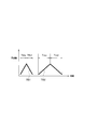
- FIG. 2 is a diagram illustrating the first sub-modulation signals TS1 and TS2.
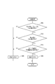
- FIG. 3 is a flowchart of processing executed by the control unit in the first embodiment.
- FIG. 4 is a graph illustrating the frequency-intensity relationship of beat signals acquired at each time length Tbu, Tbd, Tau, and Tad of the modulation signal.
- FIG. 5 is a flowchart showing details of the oscillation determination process of the first embodiment.
- FIG. 6 is a diagram illustrating an example in which the peak frequencies Px1, Px2, Py3, and Py4 of different targets coincide.
- FIG. 7 is a flowchart of processing executed by the control unit in the second embodiment.
- FIG. 8 is a graph illustrating the frequency-intensity relationship of the beat signal acquired at each time length Tbu, Tbd, Tau, Tad of the modulation signal.
- An FMCW radar apparatus 1 according to this embodiment shown in FIG. 1 is mounted on a vehicle and emits millimeter-wave radio waves in the traveling direction of the vehicle, for example, forward. Then, by receiving a radio wave reflected by a target such as a preceding vehicle or an obstacle as an incoming wave, a distance from the own device to the target and a relative speed of the target with respect to the own device are obtained.
- the FMCW radar device 1 for a vehicle is mounted on a vehicle, and a DAC (D / A converter) 11, a VCO (voltage control oscillator) 12, a BA (buffer amplifier) 13, A distributor 14, a PA (power amplifier) 15, and a transmission antenna 16 are provided.
- the FMCW radar apparatus 1 has a plurality of receiving antennas 18a, 18b, 18c to 18x as a receiving unit, and a plurality of mixers 19a, 19b, and 19c corresponding to the receiving antennas 18a, 18b, 18c to 18x on a one-to-one basis. To 19x.
- the FMCW radar apparatus 1 further includes a BBAMP (baseband amplifier) 20, an ADC 21, and a control unit 22.
- BBAMP baseband amplifier
- the vehicle is provided with a CAN (controller area network) 2 as an in-vehicle LAN (local area network), and a power supply bias circuit 10 for supplying a power supply voltage to the FMCW radar devices 1 and CAN2.
- the power supply bias circuit 10 receives an IG (ignition) line and a GND (ground) line of the vehicle. When the IG is on, a predetermined DC power supply voltage is applied to each part 11, 12, 13, 15, 17 of the FMCW radar device 1. , 19, 20, 22, 22 and CAN2, etc.
- the DC power supply voltage must be supplied to the transmission unit and the control unit.
- the receiving unit does not necessarily need to supply the DC power supply voltage depending on the circuit configuration, but the receiving unit according to the present embodiment has a configuration that requires the DC power supply voltage.
- the DAC 11 is a DA converter that converts a triangular wave-shaped digital signal having a predetermined length input from the control unit 22 into an adjustment level of the VCO 12 and outputs it as a triangular wave-like analog modulation signal having a predetermined period.
- the VCO 12 outputs a signal (corresponding to a regular signal) frequency-modulated by a triangular wave-like analog modulation signal input from the DAC 11, and the BA 13 amplifies and outputs this signal.
- a signal output from the VCO 12 is a millimeter-wave band signal (for example, a signal having a center frequency of 76.5 and a frequency fluctuation width of 300 MHz). More specifically, it is a signal having an ascending portion in which the frequency increases linearly sequentially in synchronization with the input triangular-wave analog modulation signal and a descending portion in which the frequency decreases linearly sequentially immediately after the ascending portion.
- the distributor 14 distributes power of the signal output from the BA 13 in two directions to generate a local signal and a transmission signal.
- the transmission signal from the distributor 14 is input to the PA 15 and amplified, and the local signal is amplified by the LA 17 and input to the plurality of mixers 19a to 19x.
- the transmission signal amplified by the PA 15 is input to the antenna 16.
- the antenna 16 transmits a millimeter-wave transmission signal having an ascending portion where the frequency rises linearly sequentially and a descending portion where the frequency falls linearly sequentially immediately after the ascending portion.
- the plurality of receiving antennas 18a to 18x are arranged side by side in the horizontal direction, and constitute one array antenna as a whole.
- Each of the plurality of reception antennas 18a to 18x receives a reception signal transmitted from the transmission antenna 16 and reflected as a result of the object.
- Each of the plurality of mixers 19a to 19x generates a known beat signal by mixing the reception signal received by the corresponding reception antenna and the local signal transmitted from the distributor 14.
- the frequency of the beat signal generated at this time is called the beat frequency
- the beat frequency of the rising part where the frequency of the transmission signal increases is the beat frequency at the time of uplink modulation
- the beat frequency of the falling part where the frequency of the transmission signal decreases It is called the beat frequency at the time of downstream modulation, and is used for calculation of the distance and relative speed of the object by the FMCW method.
- the BBAMP 20 amplifies the beat signal output from each of the plurality of mixers 19a to 19x and inputs it to the ADC 21.
- the ADC 21 is an AD converter that converts the beat signal input to the BBAMP 20 into a digital signal and inputs the digital signal to the control unit 22.
- the control unit 22 inputs a triangular wave-shaped digital signal having a predetermined period to the DAC 11 as described above at a predetermined sampling timing that is periodically repeated, and acquires each beat signal input from the ADC 21 to be described later.
- the distance from the own machine to the target, the direction of the target seen from the own machine, and the relative speed of the target with respect to the own machine are detected, and an in-vehicle device such as a pre-crash control ECU via CAN 2
- the distance, azimuth and relative speed are transmitted.
- the control unit 22 inputs a triangular wave digital signal having a predetermined cycle to the DAC 11 as described above at each predetermined sampling timing that is periodically and repeatedly visited.
- the input triangular wave digital signal is a two-sweep signal including two sweeps in which the intensity increases once and then decreases once.
- the input triangular waveform digital signal is a signal including the first type triangular waveform digital signal and the second type triangular waveform digital signal in this order.
- the modulation signal (transmission signal, local signal) output from the BA 13 becomes two types of first sub-modulation signals TS1 and TS2 as shown in FIG. That is, the BA 13 has, at one sampling timing, the first sub modulation signal TS1 corresponding to the first type of triangular wave digital signal and the second sub modulation signal TS2 corresponding to the second type of triangular wave digital signal. Are output in this order. Note that the time interval from the end of output of the first sub-modulation signal TS1 to the start of output of the second sub-modulation signal TS2 is about 5 msec or less.
- the first sub-modulation signal TS1 and the second sub-modulation signal TS2 have different upstream times Tbu and Tau and different downstream times Tbd and Tad.
- the upstream times Tbu and Tau are time lengths (reception data acquisition times) in which the frequency rises in the first sub-modulated signals TS1 and TS2, respectively, and the downstream times Tbd and Tad are the first sub-modulated signals, respectively. This is the time length (reception data acquisition time) of the section where the frequency decreases in TS1 and TS2.
- the upstream time Tbu of the modulated signal TS1 is shorter than the upstream time Tau of the modulated signal TS2, and the downstream time Tbd of the modulated signal TS1 is shorter than the downstream time Tad of the modulated signal TS2. short.
- Tbu, Tba, Tau, and Tad are set to 0.5 ms, 0.5 ms, 1 ms, and 1 ms, respectively. Further, the frequency displacement width (difference between the maximum value and the minimum value) of the first sub-modulation signals TS1, TS2 is set to the same 300 MHz.
- control unit 22 inputs a triangular wave digital signal having a predetermined period to the DAC 11 and simultaneously executes the processing shown in FIG.
- the processing in FIG. 3 is also executed by the control unit 22 at every sampling timing.
- step 110 the beat signal of each channel input from the ADC 21 is acquired as the beat signal corresponding to the first sub-modulation signal TS1 at the upstream time Tbu and the downstream time Tbd.
- the channel is a concept corresponding to the plurality of receiving antennas constituting the array antenna on a one-to-one basis.
- the beat signal of the channel of the reception antenna 18a is a beat signal generated from the reception signal received by the reception antenna 18a.
- Each beat signal to be acquired is a beat signal for one sweep in the upstream time Tbu (that is, the first rising portion) and the downstream time Tbd (that is, the first falling portion).
- step 115 fast Fourier transform (FFT, which corresponds to an example of discrete Fourier transform) is independently applied to the upstream time Tbu portion and the downstream time Tbd portion of the beat signal of each channel.
- FFT fast Fourier transform
- the frequency-intensity characteristic of the upstream time Tbu (first rising part) and the frequency-intensity characteristic of the downstream time Tbd (first downward part) are obtained for each channel.
- the first ascending part may have a target (may be zero or one). And a peak frequency (the same number as the target as a whole) is specified for each), and the receiving direction corresponding to the peak frequency (corresponding to the direction of the corresponding target) is estimated. .
- the first descending part can detect the target (may be zero, may be one, or may be plural). 1 peak frequency (the same number as the target as a whole) is specified for each, and the receiving direction (corresponding to the direction of the corresponding target) corresponding to the peak frequency is estimated.
- step 120 In the azimuth estimation in step 120, a well-known DBF (Digital Beam Forming) technique is used.
- DBF Digital Beam Forming
- a pair match is performed. Specifically, a pair of peak frequencies corresponding to the same target (peak frequency 1 of the first descending part) between the peak frequency of the first ascending part specified in step 120 and the peak frequency of the first descending part. And a pair consisting of one peak frequency of the first rising portion (hereinafter also referred to as a B pair).
- the number of B pairs extracted is the same as the number of targets. Therefore, if there are a plurality of targets, a plurality of pairs are extracted.
- the difference in the intensity of the beat signal at the peak frequency (that is, the peak intensity) is within a predetermined intensity range, and the reception azimuth corresponding to the peak frequency is within a predetermined azimuth range
- a method of extracting a pair having a history that is close to the frequency estimated from the measurement data at the previous sampling timing is employed.
- one peak Y is selected from the first ascending portion, and further, the difference in reception azimuth with respect to this one peak Y is within a predetermined azimuth range and the difference in peak intensity is within a predetermined intensity range.
- the difference in reception azimuth with respect to this one peak Y is within a predetermined azimuth range and the difference in peak intensity is within a predetermined intensity range.
- step 130 targetting is performed for each B pair extracted in step 125.
- the peak frequency of the target B pair is used to determine the distance from the own device to the target corresponding to the target B pair, the relative speed of the target with respect to the own device, and the target viewed from the own device. Is calculated, and the calculation result is used as the target data of the B pair.
- the targets (targets corresponding to the B pairs for which the target data has been created) that have been targeted in step 130 are referred to as B targets.
- ⁇ Fb is the frequency displacement width of the transmission signal (that is, the first sub-modulation signal TS1)
- f0b the center frequency of the transmission signal
- C is the speed of light.
- ⁇ Fb 300 MHz
- f0a 76.5 GHz.
- the azimuth estimated in step 120 for each of the two peak frequencies Use the average value.
- step 135 at the upstream time Tau and downstream time Tad, the beat signal of each channel input from the ADC 21 is acquired as a beat signal corresponding to the second sub-modulated signal TS2.
- Each beat signal to be acquired is a beat signal for one sweep in the upstream time Tau (that is, the second rising portion) and the downstream time Tad (that is, the second falling portion).
- step 140 FFT is independently applied to the upstream time Tau portion and the downstream time Tad portion of the beat signal of each channel.
- the second ascending part may have a target (may be zero or one). And a peak frequency (the same number as the target as a whole) is specified for each), and the receiving direction corresponding to the peak frequency (corresponding to the direction of the corresponding target) is estimated. .
- the second descending part can detect the target (there may be zero, one or a plurality of cases). 1 peak frequency (the same number as the target as a whole) is specified for each, and the receiving direction (corresponding to the direction of the corresponding target) corresponding to the peak frequency is estimated.
- the well-known DBF (Digital Beam Forming) technique is also used for the estimation of the orientation in step 145.
- a pair match is performed. Specifically, a pair of peak frequencies corresponding to the same target (peak frequency 1 of the second descending part) between the peak frequency of the second ascending part specified in step 145 and the peak frequency of the second descending part. And a pair consisting of one peak frequency of the second ascending part (hereinafter also referred to as A pair).
- the pair match method is the same as in step 125.
- step 155 targeting is performed for each A pair extracted in step 150.
- the peak frequency of the target A pair is used to determine the distance from the own device to the target corresponding to the target A pair, the relative speed of the target with respect to the own device, and the target viewed from the own device. Is calculated, and the calculation result is used as the target data of the A pair.
- the targets (targets corresponding to the A pair for which the target data has been created) targeted in step 155 are referred to as A targets.
- ⁇ Fa is the frequency displacement width of the transmission signal (that is, the second sub-modulation signal TS2)
- f0a the center frequency of the transmission signal
- C is the speed of light.
- FIG. 4 illustrates an upstream time (first rising portion) Tbu, a downstream time (first falling portion) Tbd of the first sub-modulated signal TS1, and an upstream time (second rising portion) Tau of the second sub-modulated signal TS2. It is a graph which illustrates the frequency-intensity relationship of the beat signal acquired in downstream time (2nd falling part) Tad. Peaks P1 to P4 in FIG. 4 are peaks corresponding to the same target (an object that actually exists), and have a relationship of fbu + fbd> fau + fad as described above.
- the power supply bias circuit 10 oscillates at a constant cycle, and as a result, the supply voltage to at least the BB system (from the mixer output to the ADC 21, for example, the ADC 21) among the BB system, the reception system, the BA system, and the PA system.
- the BB system from the mixer output to the ADC 21, for example, the ADC 21
- the BB system is a system including the BBAMP 20, the ADC 21, and the control unit 22, and the reception system is a system including the local amplifier 17, the reception antennas 18a to 18x, and the mixers 19a to 19x.
- the modulation system is a system including DAC 11 and VCO 12
- the BA system is a system including BA 13
- the PA system is a system including PA 15.
- beat signals in the respective parts Tbu, Tbd, Tau, and Tad include peaks P5 to P8 corresponding to the influence of oscillation noise in addition to the peaks P1 to P4 derived from the regular signal. become.
- Such peaks P5 to P8 are steadily generated regardless of the modulation slopes of the first sub-modulation signals TS1 and TS2. Therefore, the frequencies of the peaks P5 to P8 are the same in all of Tbu, Tbd, Tau, and Tad.
- the peaks P5 and P6 are paired by the pair match in step 125. This is because the peak intensities of the two are almost the same, the receiving directions of the two are the same, and they are constantly generated. For the same reason, the peaks P7 and P8 are paired in the pair match in step 150.
- oscillation determination is performed at step 170. In this oscillation determination, as described above, it is determined whether or not oscillation noise is superimposed on the supply voltage to the BB system due to the oscillation of the power supply bias circuit 10.
- step 205 a set obtained by extracting one beat signal peak from each part Tbu, Tbd, Tau, Tad (in the case of 0 set or 1 set) Or a plurality of sets), it is determined whether or not there is a set in which all peaks in the same set fall within the same frequency range Rf. This determination is based on the above-described difference in characteristics between the peaks P1 to P4 in the beat signal derived from the regular signal and the peaks P5 to P8 in the beat signal derived from the oscillation of the bias circuit 10.
- the width from the lowest peak frequency to the highest peak frequency in the same group is calculated, and it is determined whether or not the calculated width is equal to or less than the width of the frequency range Rf. If there is one or more pairs whose calculated width is equal to or smaller than the width of the frequency range Rf, it is determined that there is a pair that falls within the same frequency range Rf.
- step 205 it is determined that there is a set that falls within the same frequency range Rf, and the process proceeds to step 210.
- a set of peaks determined to fall within the same frequency range Rf is referred to as Pbu, Pbd, Pau, and Pad.
- step 205 it is determined that there is no set that falls within the same frequency range Rf, the process proceeds to step 225, the oscillation flag is set to OFF, and the oscillation determination ends.
- step 210 the peak intensities of all the peaks Pbu, Pbd, Pau, and Pad in the same set among the one or more peak sets Pbu, Pbd, Pau, and Pad determined to fall within the same frequency range Rf. It is determined whether or not there is a pair that falls within a predetermined peak intensity range.
- step 210 in reality, when a plurality of actual targets are detected at one sampling timing, the frequencies of peaks corresponding to different targets may coincide. Judgment.
- the frequency of the peak Px1 in the upstream time (first rising portion) Tbu of the first sub-modulation signal TS1 is The frequency is the same as the frequency of the peak Px2 at the down time (first descending portion) Tbd.
- the frequency of the peak Px3 in the upstream time (second rising portion) Tau of the second sub-modulated signal TS2 has the same value as the frequency of the peak Px4 in the downstream time (second downward portion) Tad.
- the frequency of the peak Py1 at the upstream time (first rising portion) Tbu of the first sub-modulation signal TS1 is the peak at the downstream time (first downward portion) Tbd. It becomes the same value as the frequency of Py2.
- the frequency of the peak Py3 in the upstream time (second rising portion) Tau of the second sub-modulated signal TS2 has the same value as the frequency of the peak Py4 in the downstream time (second downward portion) Tad.
- the peaks Px1 and Px2 corresponding to the first sub-modulation signal TS1 are not the same as the peaks Px3 and Px4 corresponding to the second sub-modulation signal TS2.
- the peaks Py1 and Py2 corresponding to the first sub modulation signal TS1 are not the same as the peaks Py3 and Py4 corresponding to the second sub modulation signal TS2.
- the peaks Px1 and Px2 corresponding to the target X and the peaks Py3 and Py4 corresponding to the target Y may all have the same frequency.
- the peak intensities of the peaks Px1 and Px2 corresponding to the target X are hardly equal to the peak intensities of the peaks Py3 and Py4 corresponding to the target Y. This is because the distances Dx and Dy are different between the target X and the target Y. In order for the peak intensities to be equal even though the distances Dx and Dy are different, it is necessary that the targets X and Y have a radar reflection cross section corresponding to the ratio of the distances. However, it is rare that this happens accidentally.
- the path over which the oscillation of the bias circuit 10 is superimposed on the BB system is constant regardless of the modulation slopes of the first sub-modulation signals TS1 and TS2 (that is, ⁇ Fb / Tbu, ⁇ Fb / Tbd, ⁇ Fa / Tau, ⁇ Fa / Tad). It is. Therefore, the peak intensities of beat signals P5 to P8 (see FIG. 4) derived from oscillation noise are the same regardless of the modulation gradient.
- step 210 for each of the peak sets Pbu, Pbd, Pau, Pad determined to fall within the same frequency range Rf, all the peaks Pbu, Pbd, Pau in the same set are used. , It is determined whether or not the peak intensity of the pad falls within a predetermined peak intensity range.
- the predetermined peak intensity ranges may be substantially the same range.
- the predetermined peak intensity range may be a range from the lowest peak intensity of the peak set Pbu, Pbd, Pau, Pad to be determined to the peak intensity +1 dB. Good.
- step 210 even in one set of peaks determined to fall within the same frequency range Rf, the peak intensities of all the peaks Pbu, Pbd, Pau, and Pad in the same set are within the predetermined peak intensity range. If it is determined to enter, the process proceeds to step 215.
- FIG. 4 shows an example of such a case.
- Step 225 the oscillation flag is set to OFF, and then the oscillation determination is terminated.
- step 210 for the oscillation determination the oscillation of the power supply bias circuit 10 is performed rather than always turning on the oscillation flag when there is a spectrum having the same frequency in all modulation gradients. The possibility of false detection can be reduced.
- step 215 the following determination is performed for each set of peaks Pbu, Pbd, Pau, and Pad that fall within the same frequency range Rf and have the same peak intensity.
- the peaks Pbu and Pbd corresponding to the B target targeted in step 130 are extracted from one set of peaks to be determined. Then, a target having the same distance D (within a predetermined error range) as the distance D obtained from the frequencies of the peaks Pbu and Pbd using the expression 1 is selected from the A targets targeted in step 155. Search and determine if there is such a target.
- the peaks Pbu for example, peak P5
- Pbd for example, peak P6
- the peaks Pbu and Pbd are very likely not to be peaks corresponding to the actual target, that is, likely to be noise.
- step 225 the oscillation flag is set to OFF, and the oscillation determination is terminated.
- step 220 the process proceeds to step 220.
- step 220 an A target that falls within the same frequency range Rf, has the same peak intensity, and has the same distance D as the corresponding B target (within a predetermined error range).
- the following determination is performed with each of the non-existent peak groups Pbu, Pbd, Pau, and Pad as determination targets.
- peaks Pau and Pad corresponding to the A target targeted in step 155 are extracted from one set of peaks to be determined. Then, the target having the same distance D (within a predetermined error range) as the distance D obtained from the frequencies of these peaks Pau and Pad using the formula 3 is selected from among the targets A targeted in step 130. Search and determine if there is such a target.
- the peaks Pau for example, peak P7
- Pad for example, peak P8
- the peaks Pau and Pad are peaks corresponding to the actual target, that is, not from noise, but a normal signal. This means that there is a high possibility that the peak is derived from.
- the peaks Pau and Pad are not peaks corresponding to the actual target, that is, they are likely to be noise. .
- the oscillation flag is set to OFF and the oscillation determination is terminated.
- the process proceeds to step 230, the oscillation flag is set to OFF, and the oscillation determination is performed. finish.
- step 180 it is determined whether or not the power supply bias circuit 10 has oscillation based on the result of the oscillation determination. Specifically, if the oscillation flag is on, it is determined that the power supply bias circuit 10 is oscillating and the process proceeds to step 190. If the oscillation flag is off, it is determined that the power supply bias circuit 10 is not oscillating and the process proceeds to step 185. .
- the target data (only the target data of the A target, only the target data of the B target, or only the target data of the B target may be obtained via the CAN2). And the target data of both B targets) may be transmitted to the pre-crash control ECU.
- the pre-crash control ECU When the pre-crash control ECU receives the target data, it performs well-known pre-crash control. For example, it is determined whether or not there is a target approaching at a predetermined relative speed or more within a predetermined distance from the FMCW radar apparatus 1, and only when there is an automatic brake operation in preparation for a collision with the target , Pretensioner operation, warning sound output, etc. After step 185, the process returns to step 110 after waiting for the next sampling timing.
- step 190 a signal indicating that the power supply bias circuit 10 has oscillated is output to the pre-crash control ECU or the like via CAN2. Upon receiving this signal, the pre-crash control ECU may notify the vehicle occupant of the abnormality.
- the distance measurement is terminated. That is, the process of FIG. 3 (creation and transmission of target data) is not repeated any more.
- control unit 22 determines in step 170 whether or not a predetermined oscillation condition is satisfied, and if satisfied, the oscillation flag is turned on, and if not satisfied, the oscillation flag is turned off. To do.
- the predetermined oscillation conditions include, as necessary conditions, all of condition 1 adopted in step 205, condition 2 adopted in step 210, condition 3 adopted in step 215, and condition 4 adopted in step 220.
- condition 1 among the sets that can be obtained by extracting one beat signal peak from each of the first rising portion Tbu, the first falling portion Tbd, the second rising portion Tau, and the second falling portion Tad, A condition is adopted in which there is a set in which all peaks in the same set fall within the same frequency range Rf. In this way, it is possible to detect noise that is constantly applied to the beat signal by a novel method that has not been conventionally used.
- the triangular wave digital signal input to the DAC 11 at each sampling timing by the control unit 22 is the same as in the first embodiment. Accordingly, the modulation signals (transmission signal, local signal) output from the BA 13 at each sampling timing are also the two types of first sub-modulation signals TS1 and TS2 as shown in FIG. 2, as in the first embodiment.
- control unit 22 inputs a triangular wave digital signal having a predetermined period to the DAC 11 and simultaneously executes the process shown in FIG. 7 instead of the process shown in FIG.
- step 110 the beat signal of each channel input from the ADC 21 at the upstream time Tbu and the downstream time Tbd in the same manner as in step 110 of FIG. Acquired as the corresponding beat signal.
- step 115 FFT is independently applied to the upstream time Tbu portion and the downstream time Tbd portion of the beat signal of each channel.
- FFT is independently applied to the upstream time Tbu portion and the downstream time Tbd portion of the beat signal of each channel.
- step 120 one peak frequency is identified for each target in each of the first ascending unit and the first descending unit in the same manner as in step 120 of FIG. 3, and the reception direction corresponding to the peak frequency is determined. presume.
- step 135 the beat signal of each channel input from the ADC 21 is acquired as the beat signal corresponding to the second sub-modulation signal TS2 at the upstream time Tau and downstream time Tad in the same manner as in step 135 of FIG. To do.
- step 140 FFT is independently applied to the upstream time Tau portion and the downstream time Tad portion of the beat signal of each channel.
- the beat signal corresponding to the second sub-modulated signal TS2 has a higher frequency bin width than the FFT frequency bin width corresponding to the first sub-modulated signal TS1 and the beat time corresponding to the first sub-modulated signal TS1.
- the width of the FFT frequency bin with respect to time Tau and downstream time Tad is narrower, the latter being 1 ⁇ 2 of the former.
- the beat signal based on the first sub-modulation signal TS1 and the beat signal based on the second sub-modulation signal TS2 include a peak corresponding to the same actual target at one sampling timing, the final signal is determined according to the peak. Therefore, the distance D detected by both is the same.
- fau ⁇ fbu, fad ⁇ fbd become.
- Bau INT (fau ⁇ Tau)
- Bbu INT (fbu ⁇ Tbu)
- Bad INT (fad ⁇ Tad)
- Bbd INT (fbd ⁇ Tbd).
- Bau is the peak frequency bin number as a result of FFT processing of the beat signal of the upstream time Tau
- Bbu is the peak bin number of the result of FFT processing of the beat signal of the upstream time Tbu.
- the frequency bin number is a value obtained by counting the frequency bins in order from the highest frequency with 0 being the bin closest to the frequency zero, and the unit is [bin].
- FIG. 8 illustrates an upstream time (first rising portion) Tbu, a downstream time (first falling portion) Tbd of the first sub-modulated signal TS1, and an upstream time (second rising portion) Tau of the second sub-modulated signal TS2. It is a graph which illustrates the frequency bin number-intensity relationship of the beat signal acquired in the downlink time (second descending part) Tad.
- the peaks P11 to P14 in FIG. 8 are peaks corresponding to the same one target (an actually existing object).
- a virtual peak P11 ′ is represented at the position of Bbu ⁇ Tau / Tbu corresponding to the peak P11
- a virtual peak P12 ′ is represented at the position of Bbd ⁇ Tad / Tbd corresponding to the peak P12. Yes.
- the power supply bias circuit 10 oscillates at a constant cycle, and as a result, the supply voltage to at least the BB system (from the mixer output to the ADC 21, for example, the ADC 21) among the BB system, the reception system, the BA system, and the PA system.
- the BB system from the mixer output to the ADC 21, for example, the ADC 21
- beat signals in the respective parts Tbu, Tbd, Tau, and Tad include peaks P15 to P18 corresponding to the influence of oscillation noise in addition to the peaks P11 to P14 derived from the regular signal. become.
- Such peaks P15 to P18 are constantly generated at the same frequency regardless of the modulation inclinations of the first sub-modulation signals TS1 and TS2. Therefore, the frequencies of the peaks P15 to P18 are the same in all of Tbu, Tbd, Tau, and Tad.
- a virtual peak P15 ′ is represented at the position of Bbu ⁇ Tau / Tbu corresponding to the peak P15
- a virtual peak P16 ′ is represented at the position of Bbd ⁇ Tad / Tbd corresponding to the peak P16.
- step 170 following step 145 oscillation determination is performed. In this oscillation determination, as described above, it is determined whether or not oscillation noise is superimposed on the supply voltage to the BB system due to the oscillation of the power supply bias circuit 10.
- step 305 a set of beat signals that can be extracted one by one from each part Tbu, Tau (in the case of 0 set or in the case of 1 set, multiple sets).
- the amount Bbu ⁇ Tau / Tbu is obtained by multiplying the frequency bin number Bbu of the peak of the first rising portion Tbu in the same set by Tau / Tbu (ratio of the first modulation gradient to the second modulation gradient).
- step 305 it is determined that there is a pair satisfying the relationship of Bau ⁇ Bbu ⁇ Tau / Tbu, and the process proceeds to step 310.
- step 305 it is determined that there is no set satisfying the relationship of Bau ⁇ Bbu ⁇ Tau / Tbu, the process proceeds to step 320, the oscillation flag is set to OFF, and the oscillation determination is terminated.
- step 310 the following determination is performed with each peak (for example, P15) in the upstream time Tbu satisfying the relationship of Bau ⁇ Bbu ⁇ Tau / Tbu as a determination target.
- each peak for example, P15
- the number of determination target peaks may be zero, one, or a plurality.
- the difference between the frequency bin numbers compared with the peak to be determined is equal to or less than the width of the frequency bin number range Rb (the degree of error, for example, 2 bins corresponding to ⁇ 1 bin), that is, the peak to be determined and the frequency A peak with a substantially matching bin number (Bbu ⁇ Bbd) is searched from peaks (eg, P12, P16) in the downstream time Tbd, and it is determined whether or not such a peak exists.
- Rb the degree of error, for example, 2 bins corresponding to ⁇ 1 bin
- the peak to be determined is a peak derived from the oscillation of the bias circuit 10, but if not, the peak to be determined is derived from the oscillation of the bias circuit 10. Very unlikely to be a peak.
- step 320 the oscillation flag is set to OFF, and the oscillation determination ends.
- step 315 the process proceeds to step 315.
- step 315 all sets of peaks satisfying the relationship of Bau ⁇ Bbu ⁇ Tau / Tbu and satisfying the relationship of Bbu ⁇ Bbd (that is, a set obtained by extracting one peak from each part Tbu, Tbd, Tau). , It is determined whether or not there is a set in which the peak intensities of all the peaks in the same set fall within a predetermined peak intensity range.
- step 315 when a plurality of actual targets are detected at one sampling timing, the frequency bin number of the peak corresponding to a different target happens to be Bau ⁇ Bbu ⁇ Tau / Tbu.
- the determination is made in view of the fact that the relationship of Bbu ⁇ Bbd may be satisfied.
- a typical scene in which the peak frequencies corresponding to different targets coincide with each other is the same as the scene described using FIG. 6 in the first embodiment.
- the peaks Px1, Px2, and Py3 satisfy the relationship of Bau ⁇ Bbu ⁇ Tau / Tbu and Bbu ⁇ Bbd, Bbu ⁇ Bbd.
- the peak intensities of the peaks Px1 and Px2 corresponding to the target X are hardly equal to the peak intensities of the peaks Py3 and Py4 corresponding to the target Y. .
- the path over which the oscillation of the bias circuit 10 is superimposed on the BB system is constant regardless of the modulation slopes of the first sub-modulation signals TS1 and TS2 (that is, ⁇ Fb / Tbu, ⁇ Fb / Tbd, ⁇ Fa / Tau, ⁇ Fa / Tad). It is. Accordingly, the peak intensities of beat signals P15 to P18 (see FIG. 8) derived from oscillation noise are the same regardless of the modulation gradient.
- step 315 in step 315, all pairs of peaks satisfying the relationship of Bau ⁇ Bbu ⁇ Tau / Tbu and satisfying the relationship of Bbu ⁇ Bbd (that is, each part Tbu, Tbd). , A group in which one peak is extracted from Tau), it is determined whether or not there is a group in which the peak intensities of all the peaks in the same group fall within a predetermined peak intensity range.
- the predetermined peak intensity ranges may be substantially the same range, and may be, for example, a range from the lowest peak intensity to the peak intensity + 1 dB in the set of peaks to be determined.
- step 315 If it is determined in step 315 that the peak intensities of all the peaks in the same group are within the predetermined peak intensity range even in one of the groups of peaks to be determined, the process proceeds to step 325 and the oscillation flag is set. Set to ON, and then finish the oscillation determination.
- FIG. 8 shows an example of such a case.
- step 320 If it is determined that the peak intensities of all the peaks in the same group do not fall within the predetermined peak intensity range, the process proceeds to step 320 and the oscillation flag is set to off. Thereafter, the oscillation determination is terminated.
- FIG. 6 shows an example of such a case.
- step 315 for oscillation determination oscillation always occurs when there is a pair of peaks that satisfies the relationship Bau ⁇ Bbu ⁇ Tau / Tbu and satisfies the relationship Bbu ⁇ Bbd. Rather than turning on the flag, the possibility of erroneous detection of oscillation of the power supply bias circuit 10 can be reduced.
- step 180 it is determined whether or not the power supply bias circuit 10 has oscillation based on the result of the oscillation determination. Specifically, if the oscillation flag is on, it is determined that the power supply bias circuit 10 is oscillating and the process proceeds to step 190. If the oscillation flag is off, it is determined that there is no oscillation in the power supply bias circuit 10 and the process proceeds to step 182. .
- step 182 pair matching is performed. Specifically, a pair of peak frequencies corresponding to the same target is extracted between the peak frequency of the first ascending part Tbu identified in step 120 and the peak frequency of the first descending part Tbd. Further, a pair of peak frequencies corresponding to the same target is extracted between the peak frequency of the second ascending part Tau specified in Step 140 and the peak frequency of the second descending part Tad. As the pair matching method, the same method as described in steps 125 and 150 of FIG. 3 is adopted.
- step 184 targetting is performed for each pair extracted in step 170.
- Targeting uses the peak frequency of the target pair to determine the distance from the aircraft to the target corresponding to the target pair, the relative speed of the target relative to the aircraft, and the orientation of the target as seen from the aircraft. And the calculation result is used as the target data of the pair.
- the same method as described in steps 130 and 155 of FIG. 3 is adopted.
- step 185 the target data as the result of the immediately preceding step 184 is transmitted to the pre-crash control ECU via CAN2.
- the control content of the pre-crash control ECU that has received the target data is the same as in the first embodiment.
- step 190 a signal indicating that the power supply bias circuit 10 has oscillated is output to the pre-crash control ECU or the like via CAN2. Upon receiving this signal, the pre-crash control ECU may notify the vehicle occupant of the abnormality.
- the distance measurement is terminated. That is, the processing of FIG. 7 (target data creation and transmission, etc.) is not repeated any more.
- control unit 22 determines in step 170 whether or not a predetermined oscillation condition is satisfied, and if satisfied, the oscillation flag is turned on, and if not satisfied, the oscillation flag is turned off. To do.
- the predetermined oscillation conditions include all of condition 5 adopted in step 305, condition 6 adopted in step 310, condition 7 adopted in step 315, and condition 8 adopted in step 220 as necessary conditions.
- the beat signal peaks are extracted one by one from the first ascending part Tbu and the second ascending part Tau (corresponding to an example of the changing part) based on the frequency bin-intensity characteristics of the beat signal.
- the amount Bbu ⁇ Tau / Tbu obtained by multiplying the frequency bin number Bbu of the one peak in the same set by the ratio Tau / Tbu of the first modulation gradient and the second modulation gradient.
- a condition is adopted in which it is determined that there is a pair in which the frequency bin number Bau of the peak of the variation portion Tau falls within the same bin number range (that is, Bau ⁇ Bbu ⁇ Tau / Tbu). In this way, it is possible to detect noise that is constantly applied to the beat signal by a novel method that has not been conventionally used.
- control unit 22 functions as an example of an acquisition unit by executing Steps 110 and 135 in FIGS. 2 and 7, and by executing Steps 120 and 145, It functions as an example, functions as an example of an oscillation determination unit by executing step 170, functions as an example of a notification unit by executing steps 180 and 190, and is an example of a B pair matching unit by executing step 125 And function as an example of the B target means by executing step 130, function as an example of the A pair match means by executing step 150, and execute the step 155 to execute the A target means It functions as an example of discrete Fourier transform by executing steps 115 and 140.
- this invention is not limited to above-described embodiment, In the range described in the claim, it can change suitably. Further, the above embodiments are not irrelevant to each other, and can be combined as appropriate unless the combination is clearly impossible. In each of the above-described embodiments, it is needless to say that elements constituting the embodiment are not necessarily essential unless explicitly stated as essential and clearly considered essential in principle. Yes. Further, in each of the above embodiments, when numerical values such as the number, numerical value, quantity, range, etc. of the constituent elements of the embodiment are mentioned, it is clearly limited to a specific number when clearly indicated as essential and in principle. The number is not limited to the specific number except for the case.
- Modification 1 For example, in the first and second embodiments, if the oscillation flag is turned on at a certain sampling timing, even if the oscillation flag is not turned on at an earlier sampling timing, the steps of FIG. At 180, it is determined that oscillation has occurred in the power supply bias circuit 10, and a signal indicating that oscillation has occurred is transmitted to the pre-crash control ECU.
- the sampling timing at which the oscillation flag is turned on reaches a predetermined number of times or more, it is not determined that oscillation has occurred in the power supply bias circuit 10 at step 180 in FIG. 2, and the sampling timing at which the oscillation flag is turned on. It is determined that oscillation has occurred in the power supply bias circuit 10 only when the predetermined number of times is reached, and a signal indicating that oscillation has occurred is transmitted to the pre-crash control ECU. . By doing so, it is possible to realize oscillation determination with higher accuracy.
- the peak intensity in the beat signal derived from the oscillation noise is constant regardless of the surrounding conditions. To be kept. Therefore, by using the above as the criterion for oscillation determination, the possibility of erroneous detection of oscillation of the power supply bias circuit 10 can be further reduced.
- the first sub-modulation signal TS1 includes the first ascending part Tbu and the first descending part Tbd
- the second sub-modulation signal TS2 includes the second ascending part Tau and the second descending part Tad. Have.
- the second sub modulation signal TS2 may have the second rising portion Tau but not the second falling portion Tad.
- the target data can be created by using the beat signals of the first rising portion Tbu and the first falling portion Tbd.
- the second sub-modulation signal TS2 may have the second descending part Tad but not the second ascending part Tau. Even in this case, the target data can be created by using the beat signals of the first rising portion Tbu and the first falling portion Tbd.
- the peak of the beat signal of the second descending part Tad may be used as the variable part instead of the peak of the beat signal of the second ascending part Tau.
- step 305 among the sets (one set, one set, or multiple sets) that can be obtained by extracting one beat signal peak from each part Tbu, Tad, An amount Bbu ⁇ Tad / Tbu obtained by multiplying the frequency bin number Bbu of the peak of the first rising portion Tbu in the same set by Tad / Tbu (ratio of the first modulation gradient and the second modulation gradient), and the second falling portion Tad It is determined whether or not there is a set in which the peak frequency bin number Bad falls within the same frequency bin number range Rb (that is, whether Bad ⁇ Bbu ⁇ Tad / Tbu).
- step 310 the following determination is performed with each peak in Tbu satisfying the relationship Bad ⁇ Bbu ⁇ Tad / Tbu as a determination target.
- a peak in which the difference in frequency bin number compared with the peak to be determined is equal to or less than the width of the frequency bin number range Rb (Bbu ⁇ Bbd) is searched from the peaks in Tbd, and there is no such peak. To determine.
- one peak is extracted from all pairs of peaks satisfying the relationship of Bad ⁇ Bbu ⁇ Tad / Tbu and satisfying the relationship of Bbu ⁇ Bbd (ie, each part Tbu, Tbd, Tad). For a set), it is determined whether or not there is a set in which the peak intensities of all peaks in the same set fall within a predetermined peak intensity range.
- the second sub-modulation signal TS2 is the second sub-modulation signal TS2 when the peak of the beat signal of the second descending part Tad is used as the variable part instead of the peak of the beat signal of the second ascending part Tau.
- the present invention can also be adopted when both the rising portion Tau and the second falling portion Tad are provided.
- step 305 in step 305, one set of beat signals that can be extracted one by one from each of the parts Tbd and Tad (one set is also included in the case of 0 set). Or a plurality of sets), the amount obtained by multiplying the frequency bin number Bbd of the peak of the first descending portion Tbd in the same set by Tad / Tbd (ratio between the first modulation slope and the second modulation slope).
- step 310 the following determination is performed for each peak in Tbd that satisfies the relationship Bad ⁇ Bbd ⁇ Tad / Tbd.
- a peak in which the difference in frequency bin number compared with the peak to be determined is equal to or less than the width of the frequency bin number range Rb (Bbd ⁇ Bbu) is searched from the peaks in Tbu, and there is no such peak. To determine.
- one peak is extracted from all pairs of peaks satisfying the relationship of Bad ⁇ Bbd ⁇ Tad / Tbd and satisfying the relationship of Bbd ⁇ Bbu (that is, each part Tbd, Tbu, Tad). For a set), it is determined whether or not there is a set in which the peak intensities of all peaks in the same set fall within a predetermined peak intensity range.
- the second sub-modulation signal TS2 is transmitted following the first sub-modulation signal TS1 at each sampling timing.
- the first sub modulation signal TS1 may be transmitted following the second sub modulation signal TS2.
- the first modulation gradient may be smaller than the second modulation gradient.
- the determination process in step 210 in FIG. 5 may be omitted.
- the process proceeds to step 215.
- the determination process in step 215 may be omitted, or the determination process in step 220 may be omitted.
- any two of the determination processes in steps 210, 215, and 220 may be omitted, or all of the determination processes in steps 210, 215, and 220 may be omitted.
- step 310 of FIG. 9 may be omitted.
- the process proceeds to step 315.
- the determination process in step 315 may be omitted, or both the determination processes in steps 310 and 315 may be omitted.
- the receiving antennas 18b to 18x of the above embodiments may be eliminated and only one receiving antenna 18a may be left. In that case, the mixers 19b to 19x are also discarded, and only one mixer 19b is left. In that case, the control unit 22 may not perform direction estimation in steps 120 and 145 of FIG. 3 and FIG. 7.
Landscapes
- Engineering & Computer Science (AREA)
- Radar, Positioning & Navigation (AREA)
- Remote Sensing (AREA)
- Physics & Mathematics (AREA)
- Computer Networks & Wireless Communication (AREA)
- General Physics & Mathematics (AREA)
- Electromagnetism (AREA)
- Signal Processing (AREA)
- Radar Systems Or Details Thereof (AREA)
Priority Applications (1)
| Application Number | Priority Date | Filing Date | Title |
|---|---|---|---|
| US14/653,252 US10001556B2 (en) | 2012-12-17 | 2013-12-13 | FMCW radar apparatus |
Applications Claiming Priority (2)
| Application Number | Priority Date | Filing Date | Title |
|---|---|---|---|
| JP2012-274827 | 2012-12-17 | ||
| JP2012274827A JP6036257B2 (ja) | 2012-12-17 | 2012-12-17 | Fmcwレーダ装置 |
Publications (1)
| Publication Number | Publication Date |
|---|---|
| WO2014097981A1 true WO2014097981A1 (ja) | 2014-06-26 |
Family
ID=50978315
Family Applications (1)
| Application Number | Title | Priority Date | Filing Date |
|---|---|---|---|
| PCT/JP2013/083444 Ceased WO2014097981A1 (ja) | 2012-12-17 | 2013-12-13 | Fmcwレーダ装置 |
Country Status (3)
| Country | Link |
|---|---|
| US (1) | US10001556B2 (https=) |
| JP (1) | JP6036257B2 (https=) |
| WO (1) | WO2014097981A1 (https=) |
Cited By (3)
| Publication number | Priority date | Publication date | Assignee | Title |
|---|---|---|---|---|
| US10001556B2 (en) | 2012-12-17 | 2018-06-19 | Denso Corporation | FMCW radar apparatus |
| CN109459731A (zh) * | 2018-12-13 | 2019-03-12 | 广州极飞科技有限公司 | 信号处理方法和装置、毫米波雷达 |
| CN109669180A (zh) * | 2018-12-14 | 2019-04-23 | 河海大学 | 一种连续波雷达无人机检测方法 |
Families Citing this family (11)
| Publication number | Priority date | Publication date | Assignee | Title |
|---|---|---|---|---|
| JP6364986B2 (ja) * | 2014-06-13 | 2018-08-01 | 株式会社デンソー | レーダ装置 |
| CN105866769B (zh) * | 2016-05-19 | 2017-04-12 | 哈尔滨工业大学 | 一种并行运算的多目标检测前跟踪方法 |
| JP6560165B2 (ja) * | 2016-07-08 | 2019-08-14 | 株式会社Soken | レーダ装置 |
| EP3373034B1 (en) * | 2017-03-06 | 2020-02-26 | Nxp B.V. | Apparatus for detection and ranging |
| DE102017111367A1 (de) * | 2017-05-24 | 2018-11-29 | Abb Schweiz Ag | Abstandsmesssystem, -verfahren und diese verwendendes Robotersystem |
| JP6952567B2 (ja) * | 2017-10-17 | 2021-10-20 | 株式会社デンソーテン | レーダ装置及び信号処理方法 |
| WO2020012591A1 (ja) * | 2018-07-12 | 2020-01-16 | 三菱電機株式会社 | 方向推定装置及び無線装置 |
| CN108802722B (zh) * | 2018-08-28 | 2019-04-09 | 哈尔滨工业大学 | 一种基于虚拟谱的弱目标检测前跟踪方法 |
| CN111103580B (zh) * | 2018-10-26 | 2023-06-27 | 华为技术有限公司 | 雷达信号处理方法和装置 |
| EP4012443A1 (en) * | 2020-12-08 | 2022-06-15 | Veoneer Sweden AB | A vehicle radar system |
| WO2023281948A1 (ja) * | 2021-07-05 | 2023-01-12 | 株式会社村田製作所 | レーダ装置及びレーダ装置を搭載した移動体 |
Citations (5)
| Publication number | Priority date | Publication date | Assignee | Title |
|---|---|---|---|---|
| JPH1020025A (ja) * | 1996-07-04 | 1998-01-23 | Nec Home Electron Ltd | Fm−cwレーダ装置及び対象物測距方法 |
| JPH11133144A (ja) * | 1997-10-30 | 1999-05-21 | Mitsubishi Electric Corp | Fm−cwレーダ装置 |
| JP2004085452A (ja) * | 2002-08-28 | 2004-03-18 | Toyota Central Res & Dev Lab Inc | Fm−cwレーダ装置 |
| JP2005221343A (ja) * | 2004-02-04 | 2005-08-18 | Mitsubishi Electric Corp | 車載レーダ装置 |
| JP2009222472A (ja) * | 2008-03-14 | 2009-10-01 | Fujitsu Ten Ltd | 物体認識装置及びレーダ装置 |
Family Cites Families (4)
| Publication number | Priority date | Publication date | Assignee | Title |
|---|---|---|---|---|
| JP2793487B2 (ja) | 1993-12-01 | 1998-09-03 | 本田技研工業株式会社 | Fm−cwレーダ装置 |
| JP3988571B2 (ja) * | 2001-09-17 | 2007-10-10 | 株式会社デンソー | レーダ装置 |
| JP4224096B2 (ja) | 2006-10-27 | 2009-02-12 | 三菱電機株式会社 | レーダ装置 |
| JP6036257B2 (ja) | 2012-12-17 | 2016-11-30 | 株式会社デンソー | Fmcwレーダ装置 |
-
2012
- 2012-12-17 JP JP2012274827A patent/JP6036257B2/ja active Active
-
2013
- 2013-12-13 US US14/653,252 patent/US10001556B2/en active Active
- 2013-12-13 WO PCT/JP2013/083444 patent/WO2014097981A1/ja not_active Ceased
Patent Citations (5)
| Publication number | Priority date | Publication date | Assignee | Title |
|---|---|---|---|---|
| JPH1020025A (ja) * | 1996-07-04 | 1998-01-23 | Nec Home Electron Ltd | Fm−cwレーダ装置及び対象物測距方法 |
| JPH11133144A (ja) * | 1997-10-30 | 1999-05-21 | Mitsubishi Electric Corp | Fm−cwレーダ装置 |
| JP2004085452A (ja) * | 2002-08-28 | 2004-03-18 | Toyota Central Res & Dev Lab Inc | Fm−cwレーダ装置 |
| JP2005221343A (ja) * | 2004-02-04 | 2005-08-18 | Mitsubishi Electric Corp | 車載レーダ装置 |
| JP2009222472A (ja) * | 2008-03-14 | 2009-10-01 | Fujitsu Ten Ltd | 物体認識装置及びレーダ装置 |
Cited By (4)
| Publication number | Priority date | Publication date | Assignee | Title |
|---|---|---|---|---|
| US10001556B2 (en) | 2012-12-17 | 2018-06-19 | Denso Corporation | FMCW radar apparatus |
| CN109459731A (zh) * | 2018-12-13 | 2019-03-12 | 广州极飞科技有限公司 | 信号处理方法和装置、毫米波雷达 |
| CN109669180A (zh) * | 2018-12-14 | 2019-04-23 | 河海大学 | 一种连续波雷达无人机检测方法 |
| CN109669180B (zh) * | 2018-12-14 | 2020-09-15 | 河海大学 | 一种连续波雷达无人机检测方法 |
Also Published As
| Publication number | Publication date |
|---|---|
| JP2014119353A (ja) | 2014-06-30 |
| US10001556B2 (en) | 2018-06-19 |
| US20150355321A1 (en) | 2015-12-10 |
| JP6036257B2 (ja) | 2016-11-30 |
Similar Documents
| Publication | Publication Date | Title |
|---|---|---|
| JP6036257B2 (ja) | Fmcwレーダ装置 | |
| JP5978962B2 (ja) | Fmcwレーダ装置 | |
| JP4724694B2 (ja) | 電波レーダ装置 | |
| JP4462060B2 (ja) | Fmcwレーダ装置 | |
| KR101757949B1 (ko) | 객체까지의 간격 및/또는 객체의 상대 속도의 명확한 결정을 위한 방법, 운전자 보조 시스템, 및 자동차 | |
| JP4492628B2 (ja) | 干渉判定方法,fmcwレーダ | |
| CN101162267B (zh) | 使用电子捷变雷达的目标检测装置 | |
| JP5990761B2 (ja) | レーダ装置 | |
| JP4232570B2 (ja) | 車両用レーダ装置 | |
| JP3600499B2 (ja) | Fmパルスドップラーレーダー装置 | |
| CN100538395C (zh) | 用于多个目标的间距和相对速度测量的方法和装置 | |
| JP2013213761A (ja) | レーダ装置、車載レーダシステム、及びプログラム | |
| JP2004245602A (ja) | アンテナの配列方法、及びレーダ装置 | |
| JP5693906B2 (ja) | レーダ装置 | |
| JP2014098571A (ja) | 物体検知装置、物体検知方法、物体検知プログラム、及び動作制御システム | |
| JP6212860B2 (ja) | 車載レーダ装置 | |
| JP2016045176A (ja) | 受信信号処理装置、レーダ装置、および物標検知方法 | |
| JP6244877B2 (ja) | Fmcwレーダ装置 | |
| US11953583B2 (en) | Radar assembly and method for operating a radar assembly | |
| JP6874686B2 (ja) | ターゲット情報検出システム及びターゲット情報検出方法 | |
| JP2012168119A (ja) | レーダ装置 | |
| JP2012194011A (ja) | Fm−cwレーダ装置及びそれに用いる移動目標信号検出方法 | |
| JP2016125945A (ja) | レーダ信号処理装置およびレーダ装置 | |
| JP6022400B2 (ja) | レーダ装置 |
Legal Events
| Date | Code | Title | Description |
|---|---|---|---|
| 121 | Ep: the epo has been informed by wipo that ep was designated in this application |
Ref document number: 13866020 Country of ref document: EP Kind code of ref document: A1 |
|
| NENP | Non-entry into the national phase |
Ref country code: DE |
|
| WWE | Wipo information: entry into national phase |
Ref document number: 14653252 Country of ref document: US |
|
| 122 | Ep: pct application non-entry in european phase |
Ref document number: 13866020 Country of ref document: EP Kind code of ref document: A1 |