WO2014097981A1 - Fmcw radar device - Google Patents
Fmcw radar device Download PDFInfo
- Publication number
- WO2014097981A1 WO2014097981A1 PCT/JP2013/083444 JP2013083444W WO2014097981A1 WO 2014097981 A1 WO2014097981 A1 WO 2014097981A1 JP 2013083444 W JP2013083444 W JP 2013083444W WO 2014097981 A1 WO2014097981 A1 WO 2014097981A1
- Authority
- WO
- WIPO (PCT)
- Prior art keywords
- peak
- frequency
- oscillation
- unit
- target
- Prior art date
Links
Images


Classifications
-
- G—PHYSICS
- G01—MEASURING; TESTING
- G01S—RADIO DIRECTION-FINDING; RADIO NAVIGATION; DETERMINING DISTANCE OR VELOCITY BY USE OF RADIO WAVES; LOCATING OR PRESENCE-DETECTING BY USE OF THE REFLECTION OR RERADIATION OF RADIO WAVES; ANALOGOUS ARRANGEMENTS USING OTHER WAVES
- G01S13/00—Systems using the reflection or reradiation of radio waves, e.g. radar systems; Analogous systems using reflection or reradiation of waves whose nature or wavelength is irrelevant or unspecified
- G01S13/02—Systems using reflection of radio waves, e.g. primary radar systems; Analogous systems
- G01S13/06—Systems determining position data of a target
- G01S13/08—Systems for measuring distance only
- G01S13/32—Systems for measuring distance only using transmission of continuous waves, whether amplitude-, frequency-, or phase-modulated, or unmodulated
- G01S13/34—Systems for measuring distance only using transmission of continuous waves, whether amplitude-, frequency-, or phase-modulated, or unmodulated using transmission of continuous, frequency-modulated waves while heterodyning the received signal, or a signal derived therefrom, with a locally-generated signal related to the contemporaneously transmitted signal
- G01S13/345—Systems for measuring distance only using transmission of continuous waves, whether amplitude-, frequency-, or phase-modulated, or unmodulated using transmission of continuous, frequency-modulated waves while heterodyning the received signal, or a signal derived therefrom, with a locally-generated signal related to the contemporaneously transmitted signal using triangular modulation
-
- G—PHYSICS
- G01—MEASURING; TESTING
- G01S—RADIO DIRECTION-FINDING; RADIO NAVIGATION; DETERMINING DISTANCE OR VELOCITY BY USE OF RADIO WAVES; LOCATING OR PRESENCE-DETECTING BY USE OF THE REFLECTION OR RERADIATION OF RADIO WAVES; ANALOGOUS ARRANGEMENTS USING OTHER WAVES
- G01S13/00—Systems using the reflection or reradiation of radio waves, e.g. radar systems; Analogous systems using reflection or reradiation of waves whose nature or wavelength is irrelevant or unspecified
- G01S13/02—Systems using reflection of radio waves, e.g. primary radar systems; Analogous systems
- G01S13/06—Systems determining position data of a target
- G01S13/08—Systems for measuring distance only
- G01S13/32—Systems for measuring distance only using transmission of continuous waves, whether amplitude-, frequency-, or phase-modulated, or unmodulated
- G01S13/34—Systems for measuring distance only using transmission of continuous waves, whether amplitude-, frequency-, or phase-modulated, or unmodulated using transmission of continuous, frequency-modulated waves while heterodyning the received signal, or a signal derived therefrom, with a locally-generated signal related to the contemporaneously transmitted signal
- G01S13/343—Systems for measuring distance only using transmission of continuous waves, whether amplitude-, frequency-, or phase-modulated, or unmodulated using transmission of continuous, frequency-modulated waves while heterodyning the received signal, or a signal derived therefrom, with a locally-generated signal related to the contemporaneously transmitted signal using sawtooth modulation
-
- G—PHYSICS
- G01—MEASURING; TESTING
- G01S—RADIO DIRECTION-FINDING; RADIO NAVIGATION; DETERMINING DISTANCE OR VELOCITY BY USE OF RADIO WAVES; LOCATING OR PRESENCE-DETECTING BY USE OF THE REFLECTION OR RERADIATION OF RADIO WAVES; ANALOGOUS ARRANGEMENTS USING OTHER WAVES
- G01S13/00—Systems using the reflection or reradiation of radio waves, e.g. radar systems; Analogous systems using reflection or reradiation of waves whose nature or wavelength is irrelevant or unspecified
- G01S13/88—Radar or analogous systems specially adapted for specific applications
- G01S13/93—Radar or analogous systems specially adapted for specific applications for anti-collision purposes
- G01S13/931—Radar or analogous systems specially adapted for specific applications for anti-collision purposes of land vehicles
-
- G—PHYSICS
- G01—MEASURING; TESTING
- G01S—RADIO DIRECTION-FINDING; RADIO NAVIGATION; DETERMINING DISTANCE OR VELOCITY BY USE OF RADIO WAVES; LOCATING OR PRESENCE-DETECTING BY USE OF THE REFLECTION OR RERADIATION OF RADIO WAVES; ANALOGOUS ARRANGEMENTS USING OTHER WAVES
- G01S7/00—Details of systems according to groups G01S13/00, G01S15/00, G01S17/00
- G01S7/02—Details of systems according to groups G01S13/00, G01S15/00, G01S17/00 of systems according to group G01S13/00
- G01S7/35—Details of non-pulse systems
Definitions
- the present invention relates to a radar device called a frequency-modulated continuous wave (FMCW) radar.
- FMCW frequency-modulated continuous wave
- FMCW radar There are various types of radar devices depending on the modulation method of transmission radio waves and the measurement principle. Among them, a frequency modulated continuous wave (FMCW) radar (hereinafter simply referred to as an FMCW radar device) is one of them.
- Patent Document 1 describes a technique for removing noise (noise components with small frequency and level temporal fluctuations) constantly applied to beat signals in this FMCW radar apparatus.
- An object of the present invention is to detect noise that is steadily applied to a beat signal by an unconventional method in an FMCW radar apparatus.
- Both comprise power bias circuit and (10) for supplying a power supply voltage to the transmission unit and the control unit.
- the control unit includes an acquisition unit (110, 135) for acquiring the beat signal output from the reception unit, the first rising unit, the first falling unit, and the first of the beat signal acquired by the acquisition unit.
- the inventor paid attention to the following facts.
- the distance detected by both of them is the same.
- the former and latter modulation slopes are different, the peak frequencies of the former and latter beat signals are different.
- the beat signal when oscillation of a certain period occurs in the power supply bias circuit and, as a result, oscillation noise is superimposed on the beat signal, the beat signal includes a peak corresponding to the influence of the oscillation noise. Such a peak occurs constantly regardless of the modulation slope. Therefore, the peak frequency derived from the oscillation noise is the same in all of the first ascending part, the first descending part, the second ascending part, and the 2 descending part.
- a set can be obtained by extracting one peak from each of the first rising portion, the first falling portion, the second rising portion, and the second falling portion. Among them, it is determined that the oscillation condition is satisfied based on the fact that there is a set in which all peaks in the same set fall within the same frequency range. In this way, it is possible to detect noise that is constantly applied to the beat signal by a novel method that has not been conventionally used.
- Another aspect of the FMCW radar apparatus includes a first ascending unit (Tbu) in which the frequency sequentially increases with a first modulation gradient, a first descending unit (Tbd) in which the frequency sequentially decreases with the first modulation gradient, and A transmission unit (11-16) for transmitting a transmission signal having a varying unit (Tau, Tad) whose frequency sequentially changes with a second modulation gradient different from the first modulation gradient; and the transmission signal is reflected by a target A reception unit (17, 18a to 18x, 19a to 19x) that outputs a reception signal as a result and outputs a beat signal based on the transmission signal and the reception signal, and detects a target based on the beat signal A control unit (22), and at least the transmission unit among the transmission unit, the reception unit, and the control unit, and a power supply bias circuit (10) that supplies a power supply voltage to the control unit are provided.
- Tbu first ascending unit
- Tbd first descending unit
- the control unit includes an acquisition unit (110, 135) that acquires the beat signal output from the reception unit, the first rising unit, the first lowering unit, and the first falling unit of the beat signal acquired by the acquisition unit, Discrete Fourier transform means (115, 140) that obtains frequency bin (intensity characteristics) by performing discrete Fourier transform on each of the variable portions, and oscillation determination means (170) that determines whether or not the oscillation condition is satisfied.
- acquisition unit 110, 135
- Discrete Fourier transform means 115, 140
- oscillation determination means (170) that determines whether or not the oscillation condition is satisfied.
- the oscillation determining unit is configured to select one of the first rising unit and the first falling unit based on the frequency bin-intensity characteristic obtained by the discrete Fourier transform unit, and the variable. Among the one or more sets obtained by extracting beat signal peaks one by one from the section, the first modulation slope and the second modulation slope are added to the frequency bin number (Bbu) of the one peak in the same set.
- the distance detected by both is the same.
- the peak frequencies of the former and latter beat signals are different.
- the ratio of the first modulation gradient to the second modulation gradient is added to the frequency bin number (Bbu) of one peak of the first rising portion (Tbu) and the first falling portion (Tbd).
- the frequency bin number (Bau) of the peak of the fluctuation part (Tau) are different.
- the beat signal when oscillation of a certain period occurs in the power supply bias circuit and, as a result, oscillation noise is superimposed on the beat signal, the beat signal includes a peak corresponding to the influence of the oscillation noise. Such a peak occurs constantly regardless of the modulation slope. Therefore, regarding the peak derived from the oscillation noise, the ratio of the first modulation slope to the second modulation slope is added to the frequency bin number (Bbu) of one of the first rising portion (Tbu) and the first falling portion (Tbd). The amount obtained by multiplying (Tau / Tbu) is the same as the frequency bin number (Bau) of the peak of the fluctuation portion (Tau).
- the oscillation condition In this way, it is possible to detect noise that is constantly applied to the beat signal by a novel method that has not been conventionally used.
- FIG. 1 is a configuration diagram of an FMCW radar apparatus according to various embodiments of the present invention.
- FIG. 2 is a diagram illustrating the first sub-modulation signals TS1 and TS2.
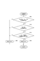
- FIG. 3 is a flowchart of processing executed by the control unit in the first embodiment.
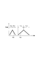
- FIG. 4 is a graph illustrating the frequency-intensity relationship of beat signals acquired at each time length Tbu, Tbd, Tau, and Tad of the modulation signal.
- FIG. 5 is a flowchart showing details of the oscillation determination process of the first embodiment.
- FIG. 6 is a diagram illustrating an example in which the peak frequencies Px1, Px2, Py3, and Py4 of different targets coincide.
- FIG. 7 is a flowchart of processing executed by the control unit in the second embodiment.
- FIG. 8 is a graph illustrating the frequency-intensity relationship of the beat signal acquired at each time length Tbu, Tbd, Tau, Tad of the modulation signal.
- An FMCW radar apparatus 1 according to this embodiment shown in FIG. 1 is mounted on a vehicle and emits millimeter-wave radio waves in the traveling direction of the vehicle, for example, forward. Then, by receiving a radio wave reflected by a target such as a preceding vehicle or an obstacle as an incoming wave, a distance from the own device to the target and a relative speed of the target with respect to the own device are obtained.
- the FMCW radar device 1 for a vehicle is mounted on a vehicle, and a DAC (D / A converter) 11, a VCO (voltage control oscillator) 12, a BA (buffer amplifier) 13, A distributor 14, a PA (power amplifier) 15, and a transmission antenna 16 are provided.
- the FMCW radar apparatus 1 has a plurality of receiving antennas 18a, 18b, 18c to 18x as a receiving unit, and a plurality of mixers 19a, 19b, and 19c corresponding to the receiving antennas 18a, 18b, 18c to 18x on a one-to-one basis. To 19x.
- the FMCW radar apparatus 1 further includes a BBAMP (baseband amplifier) 20, an ADC 21, and a control unit 22.
- BBAMP baseband amplifier
- the vehicle is provided with a CAN (controller area network) 2 as an in-vehicle LAN (local area network), and a power supply bias circuit 10 for supplying a power supply voltage to the FMCW radar devices 1 and CAN2.
- the power supply bias circuit 10 receives an IG (ignition) line and a GND (ground) line of the vehicle. When the IG is on, a predetermined DC power supply voltage is applied to each part 11, 12, 13, 15, 17 of the FMCW radar device 1. , 19, 20, 22, 22 and CAN2, etc.
- the DC power supply voltage must be supplied to the transmission unit and the control unit.
- the receiving unit does not necessarily need to supply the DC power supply voltage depending on the circuit configuration, but the receiving unit according to the present embodiment has a configuration that requires the DC power supply voltage.
- the DAC 11 is a DA converter that converts a triangular wave-shaped digital signal having a predetermined length input from the control unit 22 into an adjustment level of the VCO 12 and outputs it as a triangular wave-like analog modulation signal having a predetermined period.
- the VCO 12 outputs a signal (corresponding to a regular signal) frequency-modulated by a triangular wave-like analog modulation signal input from the DAC 11, and the BA 13 amplifies and outputs this signal.
- a signal output from the VCO 12 is a millimeter-wave band signal (for example, a signal having a center frequency of 76.5 and a frequency fluctuation width of 300 MHz). More specifically, it is a signal having an ascending portion in which the frequency increases linearly sequentially in synchronization with the input triangular-wave analog modulation signal and a descending portion in which the frequency decreases linearly sequentially immediately after the ascending portion.
- the distributor 14 distributes power of the signal output from the BA 13 in two directions to generate a local signal and a transmission signal.
- the transmission signal from the distributor 14 is input to the PA 15 and amplified, and the local signal is amplified by the LA 17 and input to the plurality of mixers 19a to 19x.
- the transmission signal amplified by the PA 15 is input to the antenna 16.
- the antenna 16 transmits a millimeter-wave transmission signal having an ascending portion where the frequency rises linearly sequentially and a descending portion where the frequency falls linearly sequentially immediately after the ascending portion.
- the plurality of receiving antennas 18a to 18x are arranged side by side in the horizontal direction, and constitute one array antenna as a whole.
- Each of the plurality of reception antennas 18a to 18x receives a reception signal transmitted from the transmission antenna 16 and reflected as a result of the object.
- Each of the plurality of mixers 19a to 19x generates a known beat signal by mixing the reception signal received by the corresponding reception antenna and the local signal transmitted from the distributor 14.
- the frequency of the beat signal generated at this time is called the beat frequency
- the beat frequency of the rising part where the frequency of the transmission signal increases is the beat frequency at the time of uplink modulation
- the beat frequency of the falling part where the frequency of the transmission signal decreases It is called the beat frequency at the time of downstream modulation, and is used for calculation of the distance and relative speed of the object by the FMCW method.
- the BBAMP 20 amplifies the beat signal output from each of the plurality of mixers 19a to 19x and inputs it to the ADC 21.
- the ADC 21 is an AD converter that converts the beat signal input to the BBAMP 20 into a digital signal and inputs the digital signal to the control unit 22.
- the control unit 22 inputs a triangular wave-shaped digital signal having a predetermined period to the DAC 11 as described above at a predetermined sampling timing that is periodically repeated, and acquires each beat signal input from the ADC 21 to be described later.
- the distance from the own machine to the target, the direction of the target seen from the own machine, and the relative speed of the target with respect to the own machine are detected, and an in-vehicle device such as a pre-crash control ECU via CAN 2
- the distance, azimuth and relative speed are transmitted.
- the control unit 22 inputs a triangular wave digital signal having a predetermined cycle to the DAC 11 as described above at each predetermined sampling timing that is periodically and repeatedly visited.
- the input triangular wave digital signal is a two-sweep signal including two sweeps in which the intensity increases once and then decreases once.
- the input triangular waveform digital signal is a signal including the first type triangular waveform digital signal and the second type triangular waveform digital signal in this order.
- the modulation signal (transmission signal, local signal) output from the BA 13 becomes two types of first sub-modulation signals TS1 and TS2 as shown in FIG. That is, the BA 13 has, at one sampling timing, the first sub modulation signal TS1 corresponding to the first type of triangular wave digital signal and the second sub modulation signal TS2 corresponding to the second type of triangular wave digital signal. Are output in this order. Note that the time interval from the end of output of the first sub-modulation signal TS1 to the start of output of the second sub-modulation signal TS2 is about 5 msec or less.
- the first sub-modulation signal TS1 and the second sub-modulation signal TS2 have different upstream times Tbu and Tau and different downstream times Tbd and Tad.
- the upstream times Tbu and Tau are time lengths (reception data acquisition times) in which the frequency rises in the first sub-modulated signals TS1 and TS2, respectively, and the downstream times Tbd and Tad are the first sub-modulated signals, respectively. This is the time length (reception data acquisition time) of the section where the frequency decreases in TS1 and TS2.
- the upstream time Tbu of the modulated signal TS1 is shorter than the upstream time Tau of the modulated signal TS2, and the downstream time Tbd of the modulated signal TS1 is shorter than the downstream time Tad of the modulated signal TS2. short.
- Tbu, Tba, Tau, and Tad are set to 0.5 ms, 0.5 ms, 1 ms, and 1 ms, respectively. Further, the frequency displacement width (difference between the maximum value and the minimum value) of the first sub-modulation signals TS1, TS2 is set to the same 300 MHz.
- control unit 22 inputs a triangular wave digital signal having a predetermined period to the DAC 11 and simultaneously executes the processing shown in FIG.
- the processing in FIG. 3 is also executed by the control unit 22 at every sampling timing.
- step 110 the beat signal of each channel input from the ADC 21 is acquired as the beat signal corresponding to the first sub-modulation signal TS1 at the upstream time Tbu and the downstream time Tbd.
- the channel is a concept corresponding to the plurality of receiving antennas constituting the array antenna on a one-to-one basis.
- the beat signal of the channel of the reception antenna 18a is a beat signal generated from the reception signal received by the reception antenna 18a.
- Each beat signal to be acquired is a beat signal for one sweep in the upstream time Tbu (that is, the first rising portion) and the downstream time Tbd (that is, the first falling portion).
- step 115 fast Fourier transform (FFT, which corresponds to an example of discrete Fourier transform) is independently applied to the upstream time Tbu portion and the downstream time Tbd portion of the beat signal of each channel.
- FFT fast Fourier transform
- the frequency-intensity characteristic of the upstream time Tbu (first rising part) and the frequency-intensity characteristic of the downstream time Tbd (first downward part) are obtained for each channel.
- the first ascending part may have a target (may be zero or one). And a peak frequency (the same number as the target as a whole) is specified for each), and the receiving direction corresponding to the peak frequency (corresponding to the direction of the corresponding target) is estimated. .
- the first descending part can detect the target (may be zero, may be one, or may be plural). 1 peak frequency (the same number as the target as a whole) is specified for each, and the receiving direction (corresponding to the direction of the corresponding target) corresponding to the peak frequency is estimated.
- step 120 In the azimuth estimation in step 120, a well-known DBF (Digital Beam Forming) technique is used.
- DBF Digital Beam Forming
- a pair match is performed. Specifically, a pair of peak frequencies corresponding to the same target (peak frequency 1 of the first descending part) between the peak frequency of the first ascending part specified in step 120 and the peak frequency of the first descending part. And a pair consisting of one peak frequency of the first rising portion (hereinafter also referred to as a B pair).
- the number of B pairs extracted is the same as the number of targets. Therefore, if there are a plurality of targets, a plurality of pairs are extracted.
- the difference in the intensity of the beat signal at the peak frequency (that is, the peak intensity) is within a predetermined intensity range, and the reception azimuth corresponding to the peak frequency is within a predetermined azimuth range
- a method of extracting a pair having a history that is close to the frequency estimated from the measurement data at the previous sampling timing is employed.
- one peak Y is selected from the first ascending portion, and further, the difference in reception azimuth with respect to this one peak Y is within a predetermined azimuth range and the difference in peak intensity is within a predetermined intensity range.
- the difference in reception azimuth with respect to this one peak Y is within a predetermined azimuth range and the difference in peak intensity is within a predetermined intensity range.
- step 130 targetting is performed for each B pair extracted in step 125.
- the peak frequency of the target B pair is used to determine the distance from the own device to the target corresponding to the target B pair, the relative speed of the target with respect to the own device, and the target viewed from the own device. Is calculated, and the calculation result is used as the target data of the B pair.
- the targets (targets corresponding to the B pairs for which the target data has been created) that have been targeted in step 130 are referred to as B targets.
- ⁇ Fb is the frequency displacement width of the transmission signal (that is, the first sub-modulation signal TS1)
- f0b the center frequency of the transmission signal
- C is the speed of light.
- ⁇ Fb 300 MHz
- f0a 76.5 GHz.
- the azimuth estimated in step 120 for each of the two peak frequencies Use the average value.
- step 135 at the upstream time Tau and downstream time Tad, the beat signal of each channel input from the ADC 21 is acquired as a beat signal corresponding to the second sub-modulated signal TS2.
- Each beat signal to be acquired is a beat signal for one sweep in the upstream time Tau (that is, the second rising portion) and the downstream time Tad (that is, the second falling portion).
- step 140 FFT is independently applied to the upstream time Tau portion and the downstream time Tad portion of the beat signal of each channel.
- the second ascending part may have a target (may be zero or one). And a peak frequency (the same number as the target as a whole) is specified for each), and the receiving direction corresponding to the peak frequency (corresponding to the direction of the corresponding target) is estimated. .
- the second descending part can detect the target (there may be zero, one or a plurality of cases). 1 peak frequency (the same number as the target as a whole) is specified for each, and the receiving direction (corresponding to the direction of the corresponding target) corresponding to the peak frequency is estimated.
- the well-known DBF (Digital Beam Forming) technique is also used for the estimation of the orientation in step 145.
- a pair match is performed. Specifically, a pair of peak frequencies corresponding to the same target (peak frequency 1 of the second descending part) between the peak frequency of the second ascending part specified in step 145 and the peak frequency of the second descending part. And a pair consisting of one peak frequency of the second ascending part (hereinafter also referred to as A pair).
- the pair match method is the same as in step 125.
- step 155 targeting is performed for each A pair extracted in step 150.
- the peak frequency of the target A pair is used to determine the distance from the own device to the target corresponding to the target A pair, the relative speed of the target with respect to the own device, and the target viewed from the own device. Is calculated, and the calculation result is used as the target data of the A pair.
- the targets (targets corresponding to the A pair for which the target data has been created) targeted in step 155 are referred to as A targets.
- ⁇ Fa is the frequency displacement width of the transmission signal (that is, the second sub-modulation signal TS2)
- f0a the center frequency of the transmission signal
- C is the speed of light.
- FIG. 4 illustrates an upstream time (first rising portion) Tbu, a downstream time (first falling portion) Tbd of the first sub-modulated signal TS1, and an upstream time (second rising portion) Tau of the second sub-modulated signal TS2. It is a graph which illustrates the frequency-intensity relationship of the beat signal acquired in downstream time (2nd falling part) Tad. Peaks P1 to P4 in FIG. 4 are peaks corresponding to the same target (an object that actually exists), and have a relationship of fbu + fbd> fau + fad as described above.
- the power supply bias circuit 10 oscillates at a constant cycle, and as a result, the supply voltage to at least the BB system (from the mixer output to the ADC 21, for example, the ADC 21) among the BB system, the reception system, the BA system, and the PA system.
- the BB system from the mixer output to the ADC 21, for example, the ADC 21
- the BB system is a system including the BBAMP 20, the ADC 21, and the control unit 22, and the reception system is a system including the local amplifier 17, the reception antennas 18a to 18x, and the mixers 19a to 19x.
- the modulation system is a system including DAC 11 and VCO 12
- the BA system is a system including BA 13
- the PA system is a system including PA 15.
- beat signals in the respective parts Tbu, Tbd, Tau, and Tad include peaks P5 to P8 corresponding to the influence of oscillation noise in addition to the peaks P1 to P4 derived from the regular signal. become.
- Such peaks P5 to P8 are steadily generated regardless of the modulation slopes of the first sub-modulation signals TS1 and TS2. Therefore, the frequencies of the peaks P5 to P8 are the same in all of Tbu, Tbd, Tau, and Tad.
- the peaks P5 and P6 are paired by the pair match in step 125. This is because the peak intensities of the two are almost the same, the receiving directions of the two are the same, and they are constantly generated. For the same reason, the peaks P7 and P8 are paired in the pair match in step 150.
- oscillation determination is performed at step 170. In this oscillation determination, as described above, it is determined whether or not oscillation noise is superimposed on the supply voltage to the BB system due to the oscillation of the power supply bias circuit 10.
- step 205 a set obtained by extracting one beat signal peak from each part Tbu, Tbd, Tau, Tad (in the case of 0 set or 1 set) Or a plurality of sets), it is determined whether or not there is a set in which all peaks in the same set fall within the same frequency range Rf. This determination is based on the above-described difference in characteristics between the peaks P1 to P4 in the beat signal derived from the regular signal and the peaks P5 to P8 in the beat signal derived from the oscillation of the bias circuit 10.
- the width from the lowest peak frequency to the highest peak frequency in the same group is calculated, and it is determined whether or not the calculated width is equal to or less than the width of the frequency range Rf. If there is one or more pairs whose calculated width is equal to or smaller than the width of the frequency range Rf, it is determined that there is a pair that falls within the same frequency range Rf.
- step 205 it is determined that there is a set that falls within the same frequency range Rf, and the process proceeds to step 210.
- a set of peaks determined to fall within the same frequency range Rf is referred to as Pbu, Pbd, Pau, and Pad.
- step 205 it is determined that there is no set that falls within the same frequency range Rf, the process proceeds to step 225, the oscillation flag is set to OFF, and the oscillation determination ends.
- step 210 the peak intensities of all the peaks Pbu, Pbd, Pau, and Pad in the same set among the one or more peak sets Pbu, Pbd, Pau, and Pad determined to fall within the same frequency range Rf. It is determined whether or not there is a pair that falls within a predetermined peak intensity range.
- step 210 in reality, when a plurality of actual targets are detected at one sampling timing, the frequencies of peaks corresponding to different targets may coincide. Judgment.
- the frequency of the peak Px1 in the upstream time (first rising portion) Tbu of the first sub-modulation signal TS1 is The frequency is the same as the frequency of the peak Px2 at the down time (first descending portion) Tbd.
- the frequency of the peak Px3 in the upstream time (second rising portion) Tau of the second sub-modulated signal TS2 has the same value as the frequency of the peak Px4 in the downstream time (second downward portion) Tad.
- the frequency of the peak Py1 at the upstream time (first rising portion) Tbu of the first sub-modulation signal TS1 is the peak at the downstream time (first downward portion) Tbd. It becomes the same value as the frequency of Py2.
- the frequency of the peak Py3 in the upstream time (second rising portion) Tau of the second sub-modulated signal TS2 has the same value as the frequency of the peak Py4 in the downstream time (second downward portion) Tad.
- the peaks Px1 and Px2 corresponding to the first sub-modulation signal TS1 are not the same as the peaks Px3 and Px4 corresponding to the second sub-modulation signal TS2.
- the peaks Py1 and Py2 corresponding to the first sub modulation signal TS1 are not the same as the peaks Py3 and Py4 corresponding to the second sub modulation signal TS2.
- the peaks Px1 and Px2 corresponding to the target X and the peaks Py3 and Py4 corresponding to the target Y may all have the same frequency.
- the peak intensities of the peaks Px1 and Px2 corresponding to the target X are hardly equal to the peak intensities of the peaks Py3 and Py4 corresponding to the target Y. This is because the distances Dx and Dy are different between the target X and the target Y. In order for the peak intensities to be equal even though the distances Dx and Dy are different, it is necessary that the targets X and Y have a radar reflection cross section corresponding to the ratio of the distances. However, it is rare that this happens accidentally.
- the path over which the oscillation of the bias circuit 10 is superimposed on the BB system is constant regardless of the modulation slopes of the first sub-modulation signals TS1 and TS2 (that is, ⁇ Fb / Tbu, ⁇ Fb / Tbd, ⁇ Fa / Tau, ⁇ Fa / Tad). It is. Therefore, the peak intensities of beat signals P5 to P8 (see FIG. 4) derived from oscillation noise are the same regardless of the modulation gradient.
- step 210 for each of the peak sets Pbu, Pbd, Pau, Pad determined to fall within the same frequency range Rf, all the peaks Pbu, Pbd, Pau in the same set are used. , It is determined whether or not the peak intensity of the pad falls within a predetermined peak intensity range.
- the predetermined peak intensity ranges may be substantially the same range.
- the predetermined peak intensity range may be a range from the lowest peak intensity of the peak set Pbu, Pbd, Pau, Pad to be determined to the peak intensity +1 dB. Good.
- step 210 even in one set of peaks determined to fall within the same frequency range Rf, the peak intensities of all the peaks Pbu, Pbd, Pau, and Pad in the same set are within the predetermined peak intensity range. If it is determined to enter, the process proceeds to step 215.
- FIG. 4 shows an example of such a case.
- Step 225 the oscillation flag is set to OFF, and then the oscillation determination is terminated.
- step 210 for the oscillation determination the oscillation of the power supply bias circuit 10 is performed rather than always turning on the oscillation flag when there is a spectrum having the same frequency in all modulation gradients. The possibility of false detection can be reduced.
- step 215 the following determination is performed for each set of peaks Pbu, Pbd, Pau, and Pad that fall within the same frequency range Rf and have the same peak intensity.
- the peaks Pbu and Pbd corresponding to the B target targeted in step 130 are extracted from one set of peaks to be determined. Then, a target having the same distance D (within a predetermined error range) as the distance D obtained from the frequencies of the peaks Pbu and Pbd using the expression 1 is selected from the A targets targeted in step 155. Search and determine if there is such a target.
- the peaks Pbu for example, peak P5
- Pbd for example, peak P6
- the peaks Pbu and Pbd are very likely not to be peaks corresponding to the actual target, that is, likely to be noise.
- step 225 the oscillation flag is set to OFF, and the oscillation determination is terminated.
- step 220 the process proceeds to step 220.
- step 220 an A target that falls within the same frequency range Rf, has the same peak intensity, and has the same distance D as the corresponding B target (within a predetermined error range).
- the following determination is performed with each of the non-existent peak groups Pbu, Pbd, Pau, and Pad as determination targets.
- peaks Pau and Pad corresponding to the A target targeted in step 155 are extracted from one set of peaks to be determined. Then, the target having the same distance D (within a predetermined error range) as the distance D obtained from the frequencies of these peaks Pau and Pad using the formula 3 is selected from among the targets A targeted in step 130. Search and determine if there is such a target.
- the peaks Pau for example, peak P7
- Pad for example, peak P8
- the peaks Pau and Pad are peaks corresponding to the actual target, that is, not from noise, but a normal signal. This means that there is a high possibility that the peak is derived from.
- the peaks Pau and Pad are not peaks corresponding to the actual target, that is, they are likely to be noise. .
- the oscillation flag is set to OFF and the oscillation determination is terminated.
- the process proceeds to step 230, the oscillation flag is set to OFF, and the oscillation determination is performed. finish.
- step 180 it is determined whether or not the power supply bias circuit 10 has oscillation based on the result of the oscillation determination. Specifically, if the oscillation flag is on, it is determined that the power supply bias circuit 10 is oscillating and the process proceeds to step 190. If the oscillation flag is off, it is determined that the power supply bias circuit 10 is not oscillating and the process proceeds to step 185. .
- the target data (only the target data of the A target, only the target data of the B target, or only the target data of the B target may be obtained via the CAN2). And the target data of both B targets) may be transmitted to the pre-crash control ECU.
- the pre-crash control ECU When the pre-crash control ECU receives the target data, it performs well-known pre-crash control. For example, it is determined whether or not there is a target approaching at a predetermined relative speed or more within a predetermined distance from the FMCW radar apparatus 1, and only when there is an automatic brake operation in preparation for a collision with the target , Pretensioner operation, warning sound output, etc. After step 185, the process returns to step 110 after waiting for the next sampling timing.
- step 190 a signal indicating that the power supply bias circuit 10 has oscillated is output to the pre-crash control ECU or the like via CAN2. Upon receiving this signal, the pre-crash control ECU may notify the vehicle occupant of the abnormality.
- the distance measurement is terminated. That is, the process of FIG. 3 (creation and transmission of target data) is not repeated any more.
- control unit 22 determines in step 170 whether or not a predetermined oscillation condition is satisfied, and if satisfied, the oscillation flag is turned on, and if not satisfied, the oscillation flag is turned off. To do.
- the predetermined oscillation conditions include, as necessary conditions, all of condition 1 adopted in step 205, condition 2 adopted in step 210, condition 3 adopted in step 215, and condition 4 adopted in step 220.
- condition 1 among the sets that can be obtained by extracting one beat signal peak from each of the first rising portion Tbu, the first falling portion Tbd, the second rising portion Tau, and the second falling portion Tad, A condition is adopted in which there is a set in which all peaks in the same set fall within the same frequency range Rf. In this way, it is possible to detect noise that is constantly applied to the beat signal by a novel method that has not been conventionally used.
- the triangular wave digital signal input to the DAC 11 at each sampling timing by the control unit 22 is the same as in the first embodiment. Accordingly, the modulation signals (transmission signal, local signal) output from the BA 13 at each sampling timing are also the two types of first sub-modulation signals TS1 and TS2 as shown in FIG. 2, as in the first embodiment.
- control unit 22 inputs a triangular wave digital signal having a predetermined period to the DAC 11 and simultaneously executes the process shown in FIG. 7 instead of the process shown in FIG.
- step 110 the beat signal of each channel input from the ADC 21 at the upstream time Tbu and the downstream time Tbd in the same manner as in step 110 of FIG. Acquired as the corresponding beat signal.
- step 115 FFT is independently applied to the upstream time Tbu portion and the downstream time Tbd portion of the beat signal of each channel.
- FFT is independently applied to the upstream time Tbu portion and the downstream time Tbd portion of the beat signal of each channel.
- step 120 one peak frequency is identified for each target in each of the first ascending unit and the first descending unit in the same manner as in step 120 of FIG. 3, and the reception direction corresponding to the peak frequency is determined. presume.
- step 135 the beat signal of each channel input from the ADC 21 is acquired as the beat signal corresponding to the second sub-modulation signal TS2 at the upstream time Tau and downstream time Tad in the same manner as in step 135 of FIG. To do.
- step 140 FFT is independently applied to the upstream time Tau portion and the downstream time Tad portion of the beat signal of each channel.
- the beat signal corresponding to the second sub-modulated signal TS2 has a higher frequency bin width than the FFT frequency bin width corresponding to the first sub-modulated signal TS1 and the beat time corresponding to the first sub-modulated signal TS1.
- the width of the FFT frequency bin with respect to time Tau and downstream time Tad is narrower, the latter being 1 ⁇ 2 of the former.
- the beat signal based on the first sub-modulation signal TS1 and the beat signal based on the second sub-modulation signal TS2 include a peak corresponding to the same actual target at one sampling timing, the final signal is determined according to the peak. Therefore, the distance D detected by both is the same.
- fau ⁇ fbu, fad ⁇ fbd become.
- Bau INT (fau ⁇ Tau)
- Bbu INT (fbu ⁇ Tbu)
- Bad INT (fad ⁇ Tad)
- Bbd INT (fbd ⁇ Tbd).
- Bau is the peak frequency bin number as a result of FFT processing of the beat signal of the upstream time Tau
- Bbu is the peak bin number of the result of FFT processing of the beat signal of the upstream time Tbu.
- the frequency bin number is a value obtained by counting the frequency bins in order from the highest frequency with 0 being the bin closest to the frequency zero, and the unit is [bin].
- FIG. 8 illustrates an upstream time (first rising portion) Tbu, a downstream time (first falling portion) Tbd of the first sub-modulated signal TS1, and an upstream time (second rising portion) Tau of the second sub-modulated signal TS2. It is a graph which illustrates the frequency bin number-intensity relationship of the beat signal acquired in the downlink time (second descending part) Tad.
- the peaks P11 to P14 in FIG. 8 are peaks corresponding to the same one target (an actually existing object).
- a virtual peak P11 ′ is represented at the position of Bbu ⁇ Tau / Tbu corresponding to the peak P11
- a virtual peak P12 ′ is represented at the position of Bbd ⁇ Tad / Tbd corresponding to the peak P12. Yes.
- the power supply bias circuit 10 oscillates at a constant cycle, and as a result, the supply voltage to at least the BB system (from the mixer output to the ADC 21, for example, the ADC 21) among the BB system, the reception system, the BA system, and the PA system.
- the BB system from the mixer output to the ADC 21, for example, the ADC 21
- beat signals in the respective parts Tbu, Tbd, Tau, and Tad include peaks P15 to P18 corresponding to the influence of oscillation noise in addition to the peaks P11 to P14 derived from the regular signal. become.
- Such peaks P15 to P18 are constantly generated at the same frequency regardless of the modulation inclinations of the first sub-modulation signals TS1 and TS2. Therefore, the frequencies of the peaks P15 to P18 are the same in all of Tbu, Tbd, Tau, and Tad.
- a virtual peak P15 ′ is represented at the position of Bbu ⁇ Tau / Tbu corresponding to the peak P15
- a virtual peak P16 ′ is represented at the position of Bbd ⁇ Tad / Tbd corresponding to the peak P16.
- step 170 following step 145 oscillation determination is performed. In this oscillation determination, as described above, it is determined whether or not oscillation noise is superimposed on the supply voltage to the BB system due to the oscillation of the power supply bias circuit 10.
- step 305 a set of beat signals that can be extracted one by one from each part Tbu, Tau (in the case of 0 set or in the case of 1 set, multiple sets).
- the amount Bbu ⁇ Tau / Tbu is obtained by multiplying the frequency bin number Bbu of the peak of the first rising portion Tbu in the same set by Tau / Tbu (ratio of the first modulation gradient to the second modulation gradient).
- step 305 it is determined that there is a pair satisfying the relationship of Bau ⁇ Bbu ⁇ Tau / Tbu, and the process proceeds to step 310.
- step 305 it is determined that there is no set satisfying the relationship of Bau ⁇ Bbu ⁇ Tau / Tbu, the process proceeds to step 320, the oscillation flag is set to OFF, and the oscillation determination is terminated.
- step 310 the following determination is performed with each peak (for example, P15) in the upstream time Tbu satisfying the relationship of Bau ⁇ Bbu ⁇ Tau / Tbu as a determination target.
- each peak for example, P15
- the number of determination target peaks may be zero, one, or a plurality.
- the difference between the frequency bin numbers compared with the peak to be determined is equal to or less than the width of the frequency bin number range Rb (the degree of error, for example, 2 bins corresponding to ⁇ 1 bin), that is, the peak to be determined and the frequency A peak with a substantially matching bin number (Bbu ⁇ Bbd) is searched from peaks (eg, P12, P16) in the downstream time Tbd, and it is determined whether or not such a peak exists.
- Rb the degree of error, for example, 2 bins corresponding to ⁇ 1 bin
- the peak to be determined is a peak derived from the oscillation of the bias circuit 10, but if not, the peak to be determined is derived from the oscillation of the bias circuit 10. Very unlikely to be a peak.
- step 320 the oscillation flag is set to OFF, and the oscillation determination ends.
- step 315 the process proceeds to step 315.
- step 315 all sets of peaks satisfying the relationship of Bau ⁇ Bbu ⁇ Tau / Tbu and satisfying the relationship of Bbu ⁇ Bbd (that is, a set obtained by extracting one peak from each part Tbu, Tbd, Tau). , It is determined whether or not there is a set in which the peak intensities of all the peaks in the same set fall within a predetermined peak intensity range.
- step 315 when a plurality of actual targets are detected at one sampling timing, the frequency bin number of the peak corresponding to a different target happens to be Bau ⁇ Bbu ⁇ Tau / Tbu.
- the determination is made in view of the fact that the relationship of Bbu ⁇ Bbd may be satisfied.
- a typical scene in which the peak frequencies corresponding to different targets coincide with each other is the same as the scene described using FIG. 6 in the first embodiment.
- the peaks Px1, Px2, and Py3 satisfy the relationship of Bau ⁇ Bbu ⁇ Tau / Tbu and Bbu ⁇ Bbd, Bbu ⁇ Bbd.
- the peak intensities of the peaks Px1 and Px2 corresponding to the target X are hardly equal to the peak intensities of the peaks Py3 and Py4 corresponding to the target Y. .
- the path over which the oscillation of the bias circuit 10 is superimposed on the BB system is constant regardless of the modulation slopes of the first sub-modulation signals TS1 and TS2 (that is, ⁇ Fb / Tbu, ⁇ Fb / Tbd, ⁇ Fa / Tau, ⁇ Fa / Tad). It is. Accordingly, the peak intensities of beat signals P15 to P18 (see FIG. 8) derived from oscillation noise are the same regardless of the modulation gradient.
- step 315 in step 315, all pairs of peaks satisfying the relationship of Bau ⁇ Bbu ⁇ Tau / Tbu and satisfying the relationship of Bbu ⁇ Bbd (that is, each part Tbu, Tbd). , A group in which one peak is extracted from Tau), it is determined whether or not there is a group in which the peak intensities of all the peaks in the same group fall within a predetermined peak intensity range.
- the predetermined peak intensity ranges may be substantially the same range, and may be, for example, a range from the lowest peak intensity to the peak intensity + 1 dB in the set of peaks to be determined.
- step 315 If it is determined in step 315 that the peak intensities of all the peaks in the same group are within the predetermined peak intensity range even in one of the groups of peaks to be determined, the process proceeds to step 325 and the oscillation flag is set. Set to ON, and then finish the oscillation determination.
- FIG. 8 shows an example of such a case.
- step 320 If it is determined that the peak intensities of all the peaks in the same group do not fall within the predetermined peak intensity range, the process proceeds to step 320 and the oscillation flag is set to off. Thereafter, the oscillation determination is terminated.
- FIG. 6 shows an example of such a case.
- step 315 for oscillation determination oscillation always occurs when there is a pair of peaks that satisfies the relationship Bau ⁇ Bbu ⁇ Tau / Tbu and satisfies the relationship Bbu ⁇ Bbd. Rather than turning on the flag, the possibility of erroneous detection of oscillation of the power supply bias circuit 10 can be reduced.
- step 180 it is determined whether or not the power supply bias circuit 10 has oscillation based on the result of the oscillation determination. Specifically, if the oscillation flag is on, it is determined that the power supply bias circuit 10 is oscillating and the process proceeds to step 190. If the oscillation flag is off, it is determined that there is no oscillation in the power supply bias circuit 10 and the process proceeds to step 182. .
- step 182 pair matching is performed. Specifically, a pair of peak frequencies corresponding to the same target is extracted between the peak frequency of the first ascending part Tbu identified in step 120 and the peak frequency of the first descending part Tbd. Further, a pair of peak frequencies corresponding to the same target is extracted between the peak frequency of the second ascending part Tau specified in Step 140 and the peak frequency of the second descending part Tad. As the pair matching method, the same method as described in steps 125 and 150 of FIG. 3 is adopted.
- step 184 targetting is performed for each pair extracted in step 170.
- Targeting uses the peak frequency of the target pair to determine the distance from the aircraft to the target corresponding to the target pair, the relative speed of the target relative to the aircraft, and the orientation of the target as seen from the aircraft. And the calculation result is used as the target data of the pair.
- the same method as described in steps 130 and 155 of FIG. 3 is adopted.
- step 185 the target data as the result of the immediately preceding step 184 is transmitted to the pre-crash control ECU via CAN2.
- the control content of the pre-crash control ECU that has received the target data is the same as in the first embodiment.
- step 190 a signal indicating that the power supply bias circuit 10 has oscillated is output to the pre-crash control ECU or the like via CAN2. Upon receiving this signal, the pre-crash control ECU may notify the vehicle occupant of the abnormality.
- the distance measurement is terminated. That is, the processing of FIG. 7 (target data creation and transmission, etc.) is not repeated any more.
- control unit 22 determines in step 170 whether or not a predetermined oscillation condition is satisfied, and if satisfied, the oscillation flag is turned on, and if not satisfied, the oscillation flag is turned off. To do.
- the predetermined oscillation conditions include all of condition 5 adopted in step 305, condition 6 adopted in step 310, condition 7 adopted in step 315, and condition 8 adopted in step 220 as necessary conditions.
- the beat signal peaks are extracted one by one from the first ascending part Tbu and the second ascending part Tau (corresponding to an example of the changing part) based on the frequency bin-intensity characteristics of the beat signal.
- the amount Bbu ⁇ Tau / Tbu obtained by multiplying the frequency bin number Bbu of the one peak in the same set by the ratio Tau / Tbu of the first modulation gradient and the second modulation gradient.
- a condition is adopted in which it is determined that there is a pair in which the frequency bin number Bau of the peak of the variation portion Tau falls within the same bin number range (that is, Bau ⁇ Bbu ⁇ Tau / Tbu). In this way, it is possible to detect noise that is constantly applied to the beat signal by a novel method that has not been conventionally used.
- control unit 22 functions as an example of an acquisition unit by executing Steps 110 and 135 in FIGS. 2 and 7, and by executing Steps 120 and 145, It functions as an example, functions as an example of an oscillation determination unit by executing step 170, functions as an example of a notification unit by executing steps 180 and 190, and is an example of a B pair matching unit by executing step 125 And function as an example of the B target means by executing step 130, function as an example of the A pair match means by executing step 150, and execute the step 155 to execute the A target means It functions as an example of discrete Fourier transform by executing steps 115 and 140.
- this invention is not limited to above-described embodiment, In the range described in the claim, it can change suitably. Further, the above embodiments are not irrelevant to each other, and can be combined as appropriate unless the combination is clearly impossible. In each of the above-described embodiments, it is needless to say that elements constituting the embodiment are not necessarily essential unless explicitly stated as essential and clearly considered essential in principle. Yes. Further, in each of the above embodiments, when numerical values such as the number, numerical value, quantity, range, etc. of the constituent elements of the embodiment are mentioned, it is clearly limited to a specific number when clearly indicated as essential and in principle. The number is not limited to the specific number except for the case.
- Modification 1 For example, in the first and second embodiments, if the oscillation flag is turned on at a certain sampling timing, even if the oscillation flag is not turned on at an earlier sampling timing, the steps of FIG. At 180, it is determined that oscillation has occurred in the power supply bias circuit 10, and a signal indicating that oscillation has occurred is transmitted to the pre-crash control ECU.
- the sampling timing at which the oscillation flag is turned on reaches a predetermined number of times or more, it is not determined that oscillation has occurred in the power supply bias circuit 10 at step 180 in FIG. 2, and the sampling timing at which the oscillation flag is turned on. It is determined that oscillation has occurred in the power supply bias circuit 10 only when the predetermined number of times is reached, and a signal indicating that oscillation has occurred is transmitted to the pre-crash control ECU. . By doing so, it is possible to realize oscillation determination with higher accuracy.
- the peak intensity in the beat signal derived from the oscillation noise is constant regardless of the surrounding conditions. To be kept. Therefore, by using the above as the criterion for oscillation determination, the possibility of erroneous detection of oscillation of the power supply bias circuit 10 can be further reduced.
- the first sub-modulation signal TS1 includes the first ascending part Tbu and the first descending part Tbd
- the second sub-modulation signal TS2 includes the second ascending part Tau and the second descending part Tad. Have.
- the second sub modulation signal TS2 may have the second rising portion Tau but not the second falling portion Tad.
- the target data can be created by using the beat signals of the first rising portion Tbu and the first falling portion Tbd.
- the second sub-modulation signal TS2 may have the second descending part Tad but not the second ascending part Tau. Even in this case, the target data can be created by using the beat signals of the first rising portion Tbu and the first falling portion Tbd.
- the peak of the beat signal of the second descending part Tad may be used as the variable part instead of the peak of the beat signal of the second ascending part Tau.
- step 305 among the sets (one set, one set, or multiple sets) that can be obtained by extracting one beat signal peak from each part Tbu, Tad, An amount Bbu ⁇ Tad / Tbu obtained by multiplying the frequency bin number Bbu of the peak of the first rising portion Tbu in the same set by Tad / Tbu (ratio of the first modulation gradient and the second modulation gradient), and the second falling portion Tad It is determined whether or not there is a set in which the peak frequency bin number Bad falls within the same frequency bin number range Rb (that is, whether Bad ⁇ Bbu ⁇ Tad / Tbu).
- step 310 the following determination is performed with each peak in Tbu satisfying the relationship Bad ⁇ Bbu ⁇ Tad / Tbu as a determination target.
- a peak in which the difference in frequency bin number compared with the peak to be determined is equal to or less than the width of the frequency bin number range Rb (Bbu ⁇ Bbd) is searched from the peaks in Tbd, and there is no such peak. To determine.
- one peak is extracted from all pairs of peaks satisfying the relationship of Bad ⁇ Bbu ⁇ Tad / Tbu and satisfying the relationship of Bbu ⁇ Bbd (ie, each part Tbu, Tbd, Tad). For a set), it is determined whether or not there is a set in which the peak intensities of all peaks in the same set fall within a predetermined peak intensity range.
- the second sub-modulation signal TS2 is the second sub-modulation signal TS2 when the peak of the beat signal of the second descending part Tad is used as the variable part instead of the peak of the beat signal of the second ascending part Tau.
- the present invention can also be adopted when both the rising portion Tau and the second falling portion Tad are provided.
- step 305 in step 305, one set of beat signals that can be extracted one by one from each of the parts Tbd and Tad (one set is also included in the case of 0 set). Or a plurality of sets), the amount obtained by multiplying the frequency bin number Bbd of the peak of the first descending portion Tbd in the same set by Tad / Tbd (ratio between the first modulation slope and the second modulation slope).
- step 310 the following determination is performed for each peak in Tbd that satisfies the relationship Bad ⁇ Bbd ⁇ Tad / Tbd.
- a peak in which the difference in frequency bin number compared with the peak to be determined is equal to or less than the width of the frequency bin number range Rb (Bbd ⁇ Bbu) is searched from the peaks in Tbu, and there is no such peak. To determine.
- one peak is extracted from all pairs of peaks satisfying the relationship of Bad ⁇ Bbd ⁇ Tad / Tbd and satisfying the relationship of Bbd ⁇ Bbu (that is, each part Tbd, Tbu, Tad). For a set), it is determined whether or not there is a set in which the peak intensities of all peaks in the same set fall within a predetermined peak intensity range.
- the second sub-modulation signal TS2 is transmitted following the first sub-modulation signal TS1 at each sampling timing.
- the first sub modulation signal TS1 may be transmitted following the second sub modulation signal TS2.
- the first modulation gradient may be smaller than the second modulation gradient.
- the determination process in step 210 in FIG. 5 may be omitted.
- the process proceeds to step 215.
- the determination process in step 215 may be omitted, or the determination process in step 220 may be omitted.
- any two of the determination processes in steps 210, 215, and 220 may be omitted, or all of the determination processes in steps 210, 215, and 220 may be omitted.
- step 310 of FIG. 9 may be omitted.
- the process proceeds to step 315.
- the determination process in step 315 may be omitted, or both the determination processes in steps 310 and 315 may be omitted.
- the receiving antennas 18b to 18x of the above embodiments may be eliminated and only one receiving antenna 18a may be left. In that case, the mixers 19b to 19x are also discarded, and only one mixer 19b is left. In that case, the control unit 22 may not perform direction estimation in steps 120 and 145 of FIG. 3 and FIG. 7.
Abstract
A frequency modulated continuous wave (FMCW) radar device transmits a transmission signal having a first increasing portion (Tbu) for which the frequency sequentially increases with a first modulation slope, a first decreasing portion (Tbd) for which the frequency sequentially decreases with the first modulation slope, a second increasing portion (Tau) for which the frequency sequentially increases with a second modulation slope that is different from the first modulation slope, and a second decreasing portion (Tad) for which the frequency sequentially decreases with the second modulation slope. For each of the beat signals (Tbu, Tbd, Tau, and Tad) acquired in response to the transmission, frequencies for a plurality of peaks (P1 to P8) are identified. Groups are made, each of which is made by extracting one peak, of the identified plurality of peaks (P1 to P8), from each of the beat signals (Tbu, Tbd, Tau, and Tad), and on the basis of the presence of a group (P5 to P8) for which all peaks in the same group fit into the same frequency range, notification is made of a vibration in a power source bias circuit.
Description
本発明は、周波数変調連続波(Frequency Modulated Continuous Wave:FMCW)レーダと呼ばれるレーダ装置に関する。
The present invention relates to a radar device called a frequency-modulated continuous wave (FMCW) radar.
レーダ装置には送信電波の変調方式と測定原理に応じて様々なタイプの装置がある。このうち、周波数変調連続波(Frequency Modulated Continuous Wave:FMCW)レーダ(以下、単にFMCWレーダ装置と呼ぶ)もその一つである。
特許文献1には、このFMCWレーダ装置において、ビート信号に定常的に印加されるノイズ(周波数およびレベルの時間変動が小さいノイズ成分)を除去する技術が記載されている。 There are various types of radar devices depending on the modulation method of transmission radio waves and the measurement principle. Among them, a frequency modulated continuous wave (FMCW) radar (hereinafter simply referred to as an FMCW radar device) is one of them.
Patent Document 1 describes a technique for removing noise (noise components with small frequency and level temporal fluctuations) constantly applied to beat signals in this FMCW radar apparatus.
特許文献1には、このFMCWレーダ装置において、ビート信号に定常的に印加されるノイズ(周波数およびレベルの時間変動が小さいノイズ成分)を除去する技術が記載されている。 There are various types of radar devices depending on the modulation method of transmission radio waves and the measurement principle. Among them, a frequency modulated continuous wave (FMCW) radar (hereinafter simply referred to as an FMCW radar device) is one of them.
本発明は、FMCWレーダ装置において、従来に無い方法でビート信号に定常的に印加されるノイズを検出することを目的とする。
An object of the present invention is to detect noise that is steadily applied to a beat signal by an unconventional method in an FMCW radar apparatus.
上記目的を達成するための、本発明に係るFMCWレーダ装置の第1の態様によれば、周波数が第1変調傾きで順次上昇する第1上昇部(Tbu)、周波数が前記第1変調傾きで順次下降する第1下降部(Tbd)、周波数が前記第1変調傾きとは異なる第2変調傾きで順次上昇する第2上昇部(Tau)、および、周波数が前記第2変調傾きで順次下降する第2下降部(Tad)を有する送信信号を送信する送信部(11~16)と、前記送信信号が物標で反射された結果の受信信号を受信すると共に、前記送信信号と前記受信信号に基づくビート信号を出力する受信部(17、18a~18x、19a~19x)と、前記ビート信号に基づいて物標を検出する制御部(22)と、前記送信部、前記受信部、及び前記制御部のうちの少なくとも当該送信部と当該制御部に電源電圧を供給する電源バイアス回路(10)とを備える。前記制御部は、前記受信部が出力した前記ビート信号を取得する取得手段(110、135)と、前記取得手段が取得した前記ビート信号の前記第1上昇部、前記第1下降部、前記第2上昇部、および前記第2下降部のそれぞれについて、複数のピークの周波数を特定するピーク周波数特定手段(120、145)と、発振条件を満たすか否かを判定する発振判定手段(170)と、前記発振条件が満たされたと前記発振判定手段が判定したことに基づいて、前記電源バイアス回路に発振があることを通知する通知手段(180、190)と、を備え、前記発振判定手段(170)は、前記ピーク周波数特定手段が特定した前記複数のピークを対象として、前記第1上昇部、前記第1下降部、前記第2上昇部、および前記第2下降部のそれぞれから1個ずつピークを抽出してできる組のうち、同じ組内のすべてのピークが同一の周波数範囲(Rf)内に入る組が有ることに基づいて、前記発振条件が満たされたと判定する。
In order to achieve the above object, according to the first aspect of the FMCW radar apparatus of the present invention, the first rising portion (Tbu) in which the frequency sequentially increases with the first modulation gradient, and the frequency with the first modulation gradient. A first descending portion (Tbd) that sequentially descends, a second ascending portion (Tau) that sequentially increases with a second modulation gradient different from the first modulation gradient, and a frequency that sequentially decreases with the second modulation gradient. A transmission unit (11-16) for transmitting a transmission signal having a second descending part (Tad); and a reception signal as a result of reflection of the transmission signal by a target; and the transmission signal and the reception signal A receiving unit (17, 18a to 18x, 19a to 19x) for outputting a beat signal based thereon, a control unit (22) for detecting a target based on the beat signal, the transmitting unit, the receiving unit, and the control Small part Both comprise power bias circuit and (10) for supplying a power supply voltage to the transmission unit and the control unit. The control unit includes an acquisition unit (110, 135) for acquiring the beat signal output from the reception unit, the first rising unit, the first falling unit, and the first of the beat signal acquired by the acquisition unit. 2 for each of the ascending part and the second descending part, peak frequency specifying means (120, 145) for specifying a plurality of peak frequencies, and oscillation determining means (170) for determining whether or not an oscillation condition is satisfied Notification means (180, 190) for notifying that the power supply bias circuit is oscillating based on the fact that the oscillation determination means determines that the oscillation condition is satisfied, and the oscillation determination means (170) ) For each of the plurality of peaks identified by the peak frequency identification means, the first ascending part, the first descending part, the second ascending part, and the second descending part, respectively. Of the set which can be extracted one by one peak from determines all peaks in the same set is based on a set entering there be the same frequency range (Rf) in, and the oscillation condition is satisfied.
前記目的を達成するため、発明者は、以下の事実に着目した。第1上昇部(Tbu)および第1下降部(Tbd)から成る部分と第2上昇部(Tau)および第2下降部(Tad)から成る部分の両方で同じ現実の物標を検出した場合、両方で検出する距離(FMCWレーダ装置から当該物標までの距離)は同じになる。しかし、前者と後者の変調傾きが異なる場合は、前者と後者のビート信号のピークの周波数が異なる。
In order to achieve the above object, the inventor paid attention to the following facts. When the same real target is detected in both the portion composed of the first ascending portion (Tbu) and the first descending portion (Tbd) and the portion composed of the second ascending portion (Tau) and the second descending portion (Tad), The distance detected by both of them (the distance from the FMCW radar device to the target) is the same. However, when the former and latter modulation slopes are different, the peak frequencies of the former and latter beat signals are different.
一方、電源バイアス回路に一定周期の発振が発生し、その結果、ビート信号に発振ノイズが重畳された場合、その発振ノイズの影響に相当するピークをビート信号が含むようになる。そのようなピークは、変調傾きに無関係に、定常的に発生する。したがって、発振ノイズに由来するピークの周波数は、第1上昇部、第1下降部、第2上昇部、2下降部のすべてにおいて同じになっている。
On the other hand, when oscillation of a certain period occurs in the power supply bias circuit and, as a result, oscillation noise is superimposed on the beat signal, the beat signal includes a peak corresponding to the influence of the oscillation noise. Such a peak occurs constantly regardless of the modulation slope. Therefore, the peak frequency derived from the oscillation noise is the same in all of the first ascending part, the first descending part, the second ascending part, and the 2 descending part.
第1の態様では、このような特性の違いを利用して、第1上昇部、第1下降部、第2上昇部、および第2下降部のそれぞれから1個ずつピークを抽出してできる組のうち、同じ組内のすべてのピークが同一の周波数範囲内に入る組が有ることに基づいて、発振条件が満たされたと判定する。このようにすることで、従来に無い新規な方法で、ビート信号に定常的に印加されるノイズを検出することができる。
In the first aspect, using such a difference in characteristics, a set can be obtained by extracting one peak from each of the first rising portion, the first falling portion, the second rising portion, and the second falling portion. Among them, it is determined that the oscillation condition is satisfied based on the fact that there is a set in which all peaks in the same set fall within the same frequency range. In this way, it is possible to detect noise that is constantly applied to the beat signal by a novel method that has not been conventionally used.
また、FMCWレーダ装置の別の態様は、周波数が第1変調傾きで順次上昇する第1上昇部(Tbu)、周波数が前記第1変調傾きで順次下降する第1下降部(Tbd)、および、周波数が前記第1変調傾きとは異なる第2変調傾きで順次変化する変動部(Tau、Tad)を有する送信信号を送信する送信部(11~16)と、前記送信信号が物標で反射された結果の受信信号を受信すると共に、前記送信信号と前記受信信号に基づくビート信号を出力する受信部(17、18a~18x、19a~19x)と、前記ビート信号に基づいて物標を検出する制御部(22)と、前記送信部、前記受信部、及び前記制御部のうちの少なくとも当該送信部と当該制御部に電源電圧を供給する電源バイアス回路(10)とを備える。前記制御部は、前記受信部が出力した前記ビート信号を取得する取得手段(110、135)と、前記取得手段が取得した前記ビート信号の前記第1上昇部、前記第1下降部、および前記変動部のそれぞれに対して、離散フーリエ変換を行って周波数ビン(bin)-強度特性を得る離散フーリエ変換手段(115、140)と、発振条件を満たすか否かを判定する発振判定手段(170)と、前記発振条件が満たされたと前記発振判定手段が判定したことに基づいて、前記電源バイアス回路(10)に発振があることを通知する通知手段(180、190)と、を備え、前記発振判定手段は、前記離散フーリエ変換手段によって得られた周波数ビン-強度特性に基づいて、前記第1上昇部と前記第1下降部とのうちいずれか一方、および前記変動部から1個ずつビート信号のピークを抽出してできる1個以上の組のうち、同じ組内の前記一方のピークの周波数ビン番号(Bbu)に前記第1変調傾きと前記第2変調傾きの比(Tau/Tbu)を乗算した量と、前記変動部(Tau)のピークの周波数ビン番号(Bau)とが、同一のビン数範囲内に入る組が有ると判定したことに基づいて、前記発振条件が満たされたと判定する。
Another aspect of the FMCW radar apparatus includes a first ascending unit (Tbu) in which the frequency sequentially increases with a first modulation gradient, a first descending unit (Tbd) in which the frequency sequentially decreases with the first modulation gradient, and A transmission unit (11-16) for transmitting a transmission signal having a varying unit (Tau, Tad) whose frequency sequentially changes with a second modulation gradient different from the first modulation gradient; and the transmission signal is reflected by a target A reception unit (17, 18a to 18x, 19a to 19x) that outputs a reception signal as a result and outputs a beat signal based on the transmission signal and the reception signal, and detects a target based on the beat signal A control unit (22), and at least the transmission unit among the transmission unit, the reception unit, and the control unit, and a power supply bias circuit (10) that supplies a power supply voltage to the control unit are provided. The control unit includes an acquisition unit (110, 135) that acquires the beat signal output from the reception unit, the first rising unit, the first lowering unit, and the first falling unit of the beat signal acquired by the acquisition unit, Discrete Fourier transform means (115, 140) that obtains frequency bin (intensity characteristics) by performing discrete Fourier transform on each of the variable portions, and oscillation determination means (170) that determines whether or not the oscillation condition is satisfied. ) And notifying means (180, 190) for notifying the power supply bias circuit (10) that there is oscillation based on the fact that the oscillation determining means determines that the oscillation condition is satisfied, The oscillation determining unit is configured to select one of the first rising unit and the first falling unit based on the frequency bin-intensity characteristic obtained by the discrete Fourier transform unit, and the variable. Among the one or more sets obtained by extracting beat signal peaks one by one from the section, the first modulation slope and the second modulation slope are added to the frequency bin number (Bbu) of the one peak in the same set. Based on the determination that there is a set in which the amount multiplied by the ratio (Tau / Tbu) and the frequency bin number (Bau) of the peak of the fluctuation part (Tau) fall within the same bin number range, It is determined that the oscillation condition is satisfied.
発明者は、第1上昇部(Tbu)および第1下降部(Tbd)から成る部分と変動部(Tau)から成る部分の両方で同じ現実の物標を検出した場合、両方で検出する距離(FMCWレーダ装置から当該物標までの距離)は同じになる。しかし、前者と後者の変調傾きが異なる場合は、前者と後者のビート信号のピークの周波数が異なる。周波数ビン番号に換算すると、第1上昇部(Tbu)および第1下降部(Tbd)のうち一方のピークの周波数ビン番号(Bbu)に第1変調傾きと第2変調傾きの比(Tau/Tbu)を乗算した量と、変動部(Tau)のピークの周波数ビン番号(Bau)とが異なる。
When the inventor detects the same real target in both the part composed of the first ascending part (Tbu) and the first descending part (Tbd) and the part composed of the variable part (Tau), the distance detected by both ( The distance from the FMCW radar device to the target is the same. However, when the former and latter modulation slopes are different, the peak frequencies of the former and latter beat signals are different. When converted into the frequency bin number, the ratio of the first modulation gradient to the second modulation gradient (Tau / Tbu) is added to the frequency bin number (Bbu) of one peak of the first rising portion (Tbu) and the first falling portion (Tbd). ) And the frequency bin number (Bau) of the peak of the fluctuation part (Tau) are different.
一方、電源バイアス回路に一定周期の発振が発生し、その結果、ビート信号に発振ノイズが重畳された場合、その発振ノイズの影響に相当するピークをビート信号が含むようになる。そのようなピークは、変調傾きに無関係に、定常的に発生する。したがって、発振ノイズに由来するピークに関しては、第1上昇部(Tbu)および第1下降部(Tbd)のうち一方のピークの周波数ビン番号(Bbu)に第1変調傾きと第2変調傾きの比(Tau/Tbu)を乗算した量と、変動部(Tau)のピークの周波数ビン番号(Bau)とが、同じになる。
On the other hand, when oscillation of a certain period occurs in the power supply bias circuit and, as a result, oscillation noise is superimposed on the beat signal, the beat signal includes a peak corresponding to the influence of the oscillation noise. Such a peak occurs constantly regardless of the modulation slope. Therefore, regarding the peak derived from the oscillation noise, the ratio of the first modulation slope to the second modulation slope is added to the frequency bin number (Bbu) of one of the first rising portion (Tbu) and the first falling portion (Tbd). The amount obtained by multiplying (Tau / Tbu) is the same as the frequency bin number (Bau) of the peak of the fluctuation portion (Tau).
上記の態様に係る構成によれば、このような特性の違いを利用して、ビート信号の周波数ビン-強度特性に基づいて、第1上昇部と第1下降部とのうちいずれか一方、および変動部から1個ずつビート信号のピークを抽出してできる1個以上の組のうち、同じ組内の前記一方のピークの周波数ビン番号(Bbu)に第1変調傾きと第2変調傾きの比(Tau/Tbu)を乗算した量と、前記変動部(Tau)のピークの周波数ビン番号(Bau)とが、同一のビン数範囲内に入る組が有ると判定したことに基づいて、発振条件が満たされたと判定するこのようにすることで、従来に無い新規な方法で、ビート信号に定常的に印加されるノイズを検出することができる。
According to the configuration according to the above aspect, using such a difference in characteristics, based on the frequency bin-intensity characteristics of the beat signal, one of the first rising portion and the first falling portion, and The ratio of the first modulation slope to the second modulation slope in the frequency bin number (Bbu) of the one peak in the same set out of one or more sets obtained by extracting the beat signal peaks one by one from the variation section Based on the determination that there is a pair in which the amount multiplied by (Tau / Tbu) and the frequency bin number (Bau) of the peak of the fluctuation portion (Tau) fall within the same bin number range, the oscillation condition In this way, it is possible to detect noise that is constantly applied to the beat signal by a novel method that has not been conventionally used.
なお、上記および特許請求の範囲における括弧内の符号は、特許請求の範囲に記載された用語と後述の実施形態に記載される当該用語を例示する具体物等との対応関係を示すものである。
In addition, the code | symbol in the bracket | parenthesis in the said and the claim shows the correspondence of the term described in the claim, and the concrete thing etc. which illustrate the said term described in embodiment mentioned later. .
添付図面において:
図1は、本発明の種々の実施形態に係るFMCWレーダ装置の構成図である。
図2は、第1サブ変調信号TS1、TS2を表す図である。
図3は、第1実施形態において制御部が実行する処理のフローチャートである。
図4は、変調信号の各時間長さTbu、Tbd、Tau、Tadにおいて取得するビート信号の周波数-強度関係を例示するグラフである。
図5は、第1実施形態の発振判定処理の詳細を示すフローチャートである。
図6は、異なる物標のピーク周波数Px1、Px2、Py3、Py4が偶々一致する例を示す図である。
図7は、第2実施形態において制御部が実行する処理のフローチャートである。
図8は、変調信号の各時間長さTbu、Tbd、Tau、Tadにおいて取得するビート信号の周波数-強度関係を例示するグラフである。
図9は、第2実施形態の発振判定処理の詳細を示すフローチャートである。波数ビン-強度関係を例示するグラフである。
In the attached drawing:
FIG. 1 is a configuration diagram of an FMCW radar apparatus according to various embodiments of the present invention. FIG. 2 is a diagram illustrating the first sub-modulation signals TS1 and TS2. FIG. 3 is a flowchart of processing executed by the control unit in the first embodiment. FIG. 4 is a graph illustrating the frequency-intensity relationship of beat signals acquired at each time length Tbu, Tbd, Tau, and Tad of the modulation signal. FIG. 5 is a flowchart showing details of the oscillation determination process of the first embodiment. FIG. 6 is a diagram illustrating an example in which the peak frequencies Px1, Px2, Py3, and Py4 of different targets coincide. FIG. 7 is a flowchart of processing executed by the control unit in the second embodiment. FIG. 8 is a graph illustrating the frequency-intensity relationship of the beat signal acquired at each time length Tbu, Tbd, Tau, Tad of the modulation signal. FIG. 9 is a flowchart showing details of the oscillation determination process of the second embodiment. 6 is a graph illustrating a wave number bin-intensity relationship.
(第1実施形態)
以下、本発明の第1実施形態について説明する。
図1に示す本実施形態のFMCWレーダ装置1は、車両に搭載され、その車両の進行方向、例えば前方に向けてミリ波帯の電波を出射する。そして、先行車両、障害物などの物標によって反射した電波を到来波として受信することで、自機から物標までの距離および自機に対する物標の相対速度を求めるものである。 (First embodiment)
The first embodiment of the present invention will be described below.
AnFMCW radar apparatus 1 according to this embodiment shown in FIG. 1 is mounted on a vehicle and emits millimeter-wave radio waves in the traveling direction of the vehicle, for example, forward. Then, by receiving a radio wave reflected by a target such as a preceding vehicle or an obstacle as an incoming wave, a distance from the own device to the target and a relative speed of the target with respect to the own device are obtained.
以下、本発明の第1実施形態について説明する。
図1に示す本実施形態のFMCWレーダ装置1は、車両に搭載され、その車両の進行方向、例えば前方に向けてミリ波帯の電波を出射する。そして、先行車両、障害物などの物標によって反射した電波を到来波として受信することで、自機から物標までの距離および自機に対する物標の相対速度を求めるものである。 (First embodiment)
The first embodiment of the present invention will be described below.
An
この車両用のFMCWレーダ装置1は、図1に示す通り、車両に搭載され、送信部として、DAC(D/Aコンバータ)11、VCO(電圧制御発信器)12、BA(バッファアンプ)13、分配器14、PA(パワーアンプ)15、送信アンテナ16を備えている。更にFMCWレーダ装置1は、受信部として複数個の受信アンテナ18a、18b、18c~18x、および、受信アンテナ18a、18b、18c~18xと1対1に対応する複数個のミキサ19a、19b、19c~19xを備えている。更にFMCWレーダ装置1は、BBAMP(ベースバンドアンプ)20、ADC21、および制御部22を備えている。
As shown in FIG. 1, the FMCW radar device 1 for a vehicle is mounted on a vehicle, and a DAC (D / A converter) 11, a VCO (voltage control oscillator) 12, a BA (buffer amplifier) 13, A distributor 14, a PA (power amplifier) 15, and a transmission antenna 16 are provided. Further, the FMCW radar apparatus 1 has a plurality of receiving antennas 18a, 18b, 18c to 18x as a receiving unit, and a plurality of mixers 19a, 19b, and 19c corresponding to the receiving antennas 18a, 18b, 18c to 18x on a one-to-one basis. To 19x. The FMCW radar apparatus 1 further includes a BBAMP (baseband amplifier) 20, an ADC 21, and a control unit 22.
また、車両には、車内LAN(local area network)としてのCAN(controller area network)2、および、FMCWレーダ装置1、CAN2に電源電圧を供給する電源バイアス回路10が備えられている。電源バイアス回路10は、車両のIG(ignition)線およびGND(ground)線が入力されており、IGオン時に、所定の直流電源電圧をFMCWレーダ装置1の各部11、12、13、15、17、19、20、22、22およびCAN2等に供給する。
なお、この直流電源電圧は、送信部及び制御部には必ず供給されなければならない。しかし、受信部については、その回路構成によっては、その直流電源電圧を必ずしも供給する必要はないが、本実施形態に係る受信部はその直流電源電圧を必要な構成になっている。 Further, the vehicle is provided with a CAN (controller area network) 2 as an in-vehicle LAN (local area network), and a powersupply bias circuit 10 for supplying a power supply voltage to the FMCW radar devices 1 and CAN2. The power supply bias circuit 10 receives an IG (ignition) line and a GND (ground) line of the vehicle. When the IG is on, a predetermined DC power supply voltage is applied to each part 11, 12, 13, 15, 17 of the FMCW radar device 1. , 19, 20, 22, 22 and CAN2, etc.
The DC power supply voltage must be supplied to the transmission unit and the control unit. However, the receiving unit does not necessarily need to supply the DC power supply voltage depending on the circuit configuration, but the receiving unit according to the present embodiment has a configuration that requires the DC power supply voltage.
なお、この直流電源電圧は、送信部及び制御部には必ず供給されなければならない。しかし、受信部については、その回路構成によっては、その直流電源電圧を必ずしも供給する必要はないが、本実施形態に係る受信部はその直流電源電圧を必要な構成になっている。 Further, the vehicle is provided with a CAN (controller area network) 2 as an in-vehicle LAN (local area network), and a power
The DC power supply voltage must be supplied to the transmission unit and the control unit. However, the receiving unit does not necessarily need to supply the DC power supply voltage depending on the circuit configuration, but the receiving unit according to the present embodiment has a configuration that requires the DC power supply voltage.
DAC11は、制御部22から入力される所定長さの三角波状のデジタル信号を、VCO12の調整レベルに変換して、所定周期の三角波状のアナログ変調信号として出力するDAコンバータである。
The DAC 11 is a DA converter that converts a triangular wave-shaped digital signal having a predetermined length input from the control unit 22 into an adjustment level of the VCO 12 and outputs it as a triangular wave-like analog modulation signal having a predetermined period.
VCO12は、DAC11から入力された三角波状のアナログ変調信号で周波数変調された信号(正規の信号に相当する)を出力し、BA13は、この信号を増幅して出力する。VCO12から出力される信号は、ミリ波帯の信号(例えば、中心周波数76.5、周波数変動幅300MHzの信号)である。より詳しくは、入力された三角波状のアナログ変調信号に同期して周波数が直線的に順次上昇する上昇部および上昇部の直後に周波数が直線的に順次下降する下降部とを有する信号である。
The VCO 12 outputs a signal (corresponding to a regular signal) frequency-modulated by a triangular wave-like analog modulation signal input from the DAC 11, and the BA 13 amplifies and outputs this signal. A signal output from the VCO 12 is a millimeter-wave band signal (for example, a signal having a center frequency of 76.5 and a frequency fluctuation width of 300 MHz). More specifically, it is a signal having an ascending portion in which the frequency increases linearly sequentially in synchronization with the input triangular-wave analog modulation signal and a descending portion in which the frequency decreases linearly sequentially immediately after the ascending portion.
分配器14は、BA13から出力された信号を2方に電力分配してローカル信号と送信信号を生成するものである。この分配器14からの送信信号はPA15に入力されて増幅され、ローカル信号はLA17で増幅されて複数個のミキサ19a~19xに入力されるようになっている。
The distributor 14 distributes power of the signal output from the BA 13 in two directions to generate a local signal and a transmission signal. The transmission signal from the distributor 14 is input to the PA 15 and amplified, and the local signal is amplified by the LA 17 and input to the plurality of mixers 19a to 19x.
PA15によって増幅された送信信号はアンテナ16に入力される。これにより、アンテナ16からは、周波数が直線的に順次上昇する上昇部および上昇部の直後に周波数が直線的に順次下降する下降部を有するミリ波の送信信号が送信される。
The transmission signal amplified by the PA 15 is input to the antenna 16. Thereby, the antenna 16 transmits a millimeter-wave transmission signal having an ascending portion where the frequency rises linearly sequentially and a descending portion where the frequency falls linearly sequentially immediately after the ascending portion.
複数個の受信アンテナ18a~18xは、水平方向に並んで配置され、全体で1つのアレーアンテナを構成する。これら複数個の受信アンテナ18a~18xのそれぞれは、送信アンテナ16から送信されて対象物で反射された結果の受信信号を受信する。
The plurality of receiving antennas 18a to 18x are arranged side by side in the horizontal direction, and constitute one array antenna as a whole. Each of the plurality of reception antennas 18a to 18x receives a reception signal transmitted from the transmission antenna 16 and reflected as a result of the object.
複数個のミキサ19a~19xのそれぞれは、対応する受信アンテナが受信した受信信号と、分配器14から伝えられるローカル信号とを混合して周知のビート信号を生成して出力する。このとき生成されるビート信号の周波数がビート周波数と呼ばれるもので、送信信号の周波数が増加する上昇部のビート周波数を上り変調時のビート周波数、送信信号の周波数が減少する下降部のビート周波数を下り変調時のビート周波数と呼び、FMCW方式による対象物の距離および相対速度の演算に用いられる。
Each of the plurality of mixers 19a to 19x generates a known beat signal by mixing the reception signal received by the corresponding reception antenna and the local signal transmitted from the distributor 14. The frequency of the beat signal generated at this time is called the beat frequency, and the beat frequency of the rising part where the frequency of the transmission signal increases is the beat frequency at the time of uplink modulation, and the beat frequency of the falling part where the frequency of the transmission signal decreases It is called the beat frequency at the time of downstream modulation, and is used for calculation of the distance and relative speed of the object by the FMCW method.
BBAMP20は、複数個のミキサ19a~19xの各々が出力したビート信号を増幅してADC21に入力する。ADC21は、BBAMP20入力されたビート信号をデジタル信号に変換して制御部22に入力するADコンバータである。
The BBAMP 20 amplifies the beat signal output from each of the plurality of mixers 19a to 19x and inputs it to the ADC 21. The ADC 21 is an AD converter that converts the beat signal input to the BBAMP 20 into a digital signal and inputs the digital signal to the control unit 22.
制御部22は、定期的に繰り返し訪れる所定のサンプリングタイミングにおいて上述のようにDAC11に対して所定周期の三角波状のデジタル信号を入力すると共に、ADC21から入力された各ビート信号を取得して後述する処理を行うことで、自機から物標までの距離、自機から見た物標の方位、および自機に対する物標の相対速度を検出し、CAN2を介してプリクラッシュ制御ECU等の車内装置に、当該距離、方位および相対速度を送信する。
The control unit 22 inputs a triangular wave-shaped digital signal having a predetermined period to the DAC 11 as described above at a predetermined sampling timing that is periodically repeated, and acquires each beat signal input from the ADC 21 to be described later. By performing the processing, the distance from the own machine to the target, the direction of the target seen from the own machine, and the relative speed of the target with respect to the own machine are detected, and an in-vehicle device such as a pre-crash control ECU via CAN 2 The distance, azimuth and relative speed are transmitted.
以下、上記のような構成のFMCWレーダ装置1の作動について説明する。制御部22は、定期的に繰り返し訪れる所定のサンプリングタイミングの各々において、上述の通り、DAC11に対して所定周期の三角波状のデジタル信号を入力する。
Hereinafter, the operation of the FMCW radar apparatus 1 configured as described above will be described. The control unit 22 inputs a triangular wave digital signal having a predetermined cycle to the DAC 11 as described above at each predetermined sampling timing that is periodically and repeatedly visited.
ただし、入力する三角波状のデジタル信号は、強度が1回上昇して1回下降する掃引を2回分含む、2掃引の信号となっている。具体的には、入力する三角波状のデジタル信号は第1種の三角波状のデジタル信号、および、第2種の三角波状のデジタル信号を、この順に含む信号である。
However, the input triangular wave digital signal is a two-sweep signal including two sweeps in which the intensity increases once and then decreases once. Specifically, the input triangular waveform digital signal is a signal including the first type triangular waveform digital signal and the second type triangular waveform digital signal in this order.
この結果、BA13から出力される変調信号(送信信号、ローカル信号)は、図2に示すような2種類の第1サブ変調信号TS1、TS2となる。つまり、BA13は、1つのサンプリングタイミングにおいて、第1種の三角波状のデジタル信号に対応する第1サブ変調信号TS1、および、第2種の三角波状のデジタル信号に対応する第2サブ変調信号TS2を、この順に出力する。なお、第1サブ変調信号TS1の出力終了から第2サブ変調信号TS2の出力開始までの時間間隔は、5msec程度以下である。
As a result, the modulation signal (transmission signal, local signal) output from the BA 13 becomes two types of first sub-modulation signals TS1 and TS2 as shown in FIG. That is, the BA 13 has, at one sampling timing, the first sub modulation signal TS1 corresponding to the first type of triangular wave digital signal and the second sub modulation signal TS2 corresponding to the second type of triangular wave digital signal. Are output in this order. Note that the time interval from the end of output of the first sub-modulation signal TS1 to the start of output of the second sub-modulation signal TS2 is about 5 msec or less.
ここで、第1サブ変調信号TS1と第2サブ変調信号TS2との違いについて説明する。これら第1サブ変調信号TS1と第2サブ変調信号TS2とでは、上り時間Tbu、Tauが互いに異なり、また、下り時間Tbd、Tadが互いに異なっている。
Here, a difference between the first sub modulation signal TS1 and the second sub modulation signal TS2 will be described. The first sub-modulation signal TS1 and the second sub-modulation signal TS2 have different upstream times Tbu and Tau and different downstream times Tbd and Tad.
ここで、上り時間Tbu、Tauは、それぞれ第1サブ変調信号TS1、TS2において周波数が上昇する区間の時間長(受信データ取得時間)であり、下り時間Tbd、Tadは、それぞれ第1サブ変調信号TS1、TS2において周波数が下降する区間の時間長(受信データ取得時間)である。
Here, the upstream times Tbu and Tau are time lengths (reception data acquisition times) in which the frequency rises in the first sub-modulated signals TS1 and TS2, respectively, and the downstream times Tbd and Tad are the first sub-modulated signals, respectively. This is the time length (reception data acquisition time) of the section where the frequency decreases in TS1 and TS2.
より具体的には、変調信号TS1の上り時間Tbuの方が、変調信号TS2の上り時間Tauよりも短く、かつ、変調信号TS1の下り時間Tbdの方が、変調信号TS2の下り時間Tadよりも短い。
More specifically, the upstream time Tbu of the modulated signal TS1 is shorter than the upstream time Tau of the modulated signal TS2, and the downstream time Tbd of the modulated signal TS1 is shorter than the downstream time Tad of the modulated signal TS2. short.
本実施形態では、一例として、Tbu、Tba、Tau、Tadを、それぞれ0.5ms、0.5ms、1ms、1msとする。また、各第1サブ変調信号TS1、TS2の周波数変位幅(周波数の最大値と最小値の差)は、同じ300MHzとする。
In this embodiment, as an example, Tbu, Tba, Tau, and Tad are set to 0.5 ms, 0.5 ms, 1 ms, and 1 ms, respectively. Further, the frequency displacement width (difference between the maximum value and the minimum value) of the first sub-modulation signals TS1, TS2 is set to the same 300 MHz.
制御部22は、上述の通り、DAC11に対して所定周期の三角波状のデジタル信号を入力すると同時に、図3に示す処理を実行する。この図3の処理も、制御部22によって、サンプリングタイミング毎に実行される。
As described above, the control unit 22 inputs a triangular wave digital signal having a predetermined period to the DAC 11 and simultaneously executes the processing shown in FIG. The processing in FIG. 3 is also executed by the control unit 22 at every sampling timing.
図3の処理においては、まずステップ110で、上り時間Tbuおよび下り時間Tbdにおいて、ADC21から入力された各チャンネルのビート信号を、第1サブ変調信号TS1に対応するビート信号として取得する。
In the processing of FIG. 3, first, at step 110, the beat signal of each channel input from the ADC 21 is acquired as the beat signal corresponding to the first sub-modulation signal TS1 at the upstream time Tbu and the downstream time Tbd.
ここで、チャンネルは、アレーアンテナを構成する上記複数の受信アンテナに1対1に対応する概念である。例えば、受信アンテナ18aのチャンネルのビート信号は、受信アンテナ18aが受信した受信信号から生成されたビート信号である。なお、取得する各ビート信号は、上り時間Tbu(すなわち第1上昇部)および下り時間Tbd(すなわち第1下降部)における1掃引分のビート信号である。
Here, the channel is a concept corresponding to the plurality of receiving antennas constituting the array antenna on a one-to-one basis. For example, the beat signal of the channel of the reception antenna 18a is a beat signal generated from the reception signal received by the reception antenna 18a. Each beat signal to be acquired is a beat signal for one sweep in the upstream time Tbu (that is, the first rising portion) and the downstream time Tbd (that is, the first falling portion).
続いてステップ115に進み、各チャンネルのビート信号の上記上り時間Tbuの部分および下り時間Tbdの部分に対して、独立に高速フーリエ変換(FFT。離散フーリエ変換の一例に相当する)を施す。これにより、チャンネル毎に、上り時間Tbu(第1上昇部)の周波数-強度特性および下り時間Tbd(第1下降部)の周波数-強度特性が得られる。
Subsequently, the process proceeds to step 115, where fast Fourier transform (FFT, which corresponds to an example of discrete Fourier transform) is independently applied to the upstream time Tbu portion and the downstream time Tbd portion of the beat signal of each channel. As a result, the frequency-intensity characteristic of the upstream time Tbu (first rising part) and the frequency-intensity characteristic of the downstream time Tbd (first downward part) are obtained for each channel.
続いてステップ120では、ステップ115で得られたチャンネル毎の第1上昇部の周波数-強度特性に基づいて、第1上昇部で、物標(0個の場合もあるし1個の場合もあるし複数の場合もある)毎に1つのピーク周波数(全体として物標と同じ数になる)を特定し、当該ピーク周波数に対応する受信方位(対応する物標の方位に相当する)を推定する。
Subsequently, in step 120, based on the frequency-intensity characteristics of the first ascending part for each channel obtained in step 115, the first ascending part may have a target (may be zero or one). And a peak frequency (the same number as the target as a whole) is specified for each), and the receiving direction corresponding to the peak frequency (corresponding to the direction of the corresponding target) is estimated. .
更に、ステップ115で得られたチャンネル毎の第1下降部の周波数-強度特性に基づいて、第1下降部で、物標(0個の場合もあるし1個の場合もあるし複数の場合もある)毎に1つのピーク周波数(全体として物標と同じ数になる)を特定し、当該ピーク周波数に対応する受信方位(対応する物標の方位に相当する)を推定する。
Further, based on the frequency-intensity characteristics of the first descending part for each channel obtained in step 115, the first descending part can detect the target (may be zero, may be one, or may be plural). 1 peak frequency (the same number as the target as a whole) is specified for each, and the receiving direction (corresponding to the direction of the corresponding target) corresponding to the peak frequency is estimated.
このステップ120における方位の推定では、周知のDBF(Digital Beam Forming)技術を用いる。
In the azimuth estimation in step 120, a well-known DBF (Digital Beam Forming) technique is used.
続いてステップ125では、ペアマッチを行う。具体的には、ステップ120で特定した第1上昇部のピーク周波数と、第1下降部のピーク周波数との間で、同じ物標に対応するピーク周波数のペア(第1下降部のピーク周波数1個と第1上昇部のピーク周波数1個から成るペア。以下、Bペアともいう。)を抽出する。抽出されるBペアの数は、物標の数と同じになる。したがって、物標が複数あれば、複数個のペアが抽出される。
Subsequently, in step 125, a pair match is performed. Specifically, a pair of peak frequencies corresponding to the same target (peak frequency 1 of the first descending part) between the peak frequency of the first ascending part specified in step 120 and the peak frequency of the first descending part. And a pair consisting of one peak frequency of the first rising portion (hereinafter also referred to as a B pair). The number of B pairs extracted is the same as the number of targets. Therefore, if there are a plurality of targets, a plurality of pairs are extracted.
ペアマッチの方法としては、例えば、ピーク周波数におけるビート信号の強度(すなわち、ピーク強度)の差が所定の強度範囲内にあり、かつ、ピーク周波数に対応する受信方位が所定の方位範囲内にあり、かつ前回のサンプリングタイミングにおける測定データから推定される周波数に近い、履歴が繋がるペアを抽出する方法を採用する。
As a method of pair matching, for example, the difference in the intensity of the beat signal at the peak frequency (that is, the peak intensity) is within a predetermined intensity range, and the reception azimuth corresponding to the peak frequency is within a predetermined azimuth range, In addition, a method of extracting a pair having a history that is close to the frequency estimated from the measurement data at the previous sampling timing is employed.
具体的には、第1上昇部から1つのピークYを選び、さらに、この1つのピークYに対して受信方位の差が所定の方位範囲内にあり且つピーク強度の差が所定の強度範囲内にある第1下降部のピークをすべて(ただし、下記のように除外されたものを除く)抽出し、それら抽出したピークのうち、ピーク強度が最もピークYに近いピークZを選び、このピークY、Zをペアとし、ピークZを抽出対象から除外する。そして、この手順を、予め指定した回数(例えば第1上昇部でピーク強度を大きい順に64回抽出して)繰り返す。
Specifically, one peak Y is selected from the first ascending portion, and further, the difference in reception azimuth with respect to this one peak Y is within a predetermined azimuth range and the difference in peak intensity is within a predetermined intensity range. Are extracted (except for those excluded as described below), and a peak Z whose peak intensity is closest to the peak Y is selected from these extracted peaks. , Z as a pair, and the peak Z is excluded from the extraction target. Then, this procedure is repeated a predetermined number of times (for example, extracting the peak intensity 64 times in descending order at the first ascending portion).
続いてステップ130では、ステップ125で抽出したBペア毎に、物標化を行う。物標化では、対象のBペアのピーク周波数を用いて、自機から対象のBペアに対応する物標までの距離、自機に対する当該物標の相対速度、自機から見た当該物標の方位を算出し、算出結果を当該Bペアの物標データとする。このステップ130で物標化された物標(物標化データが作成されたBペアに対応する物標)を、それぞれB物標という。
Subsequently, in step 130, targetting is performed for each B pair extracted in step 125. In the targetization, the peak frequency of the target B pair is used to determine the distance from the own device to the target corresponding to the target B pair, the relative speed of the target with respect to the own device, and the target viewed from the own device. Is calculated, and the calculation result is used as the target data of the B pair. The targets (targets corresponding to the B pairs for which the target data has been created) that have been targeted in step 130 are referred to as B targets.
ペアとなる第1上昇部のピーク周波数と第1下降部のピーク周波数に基づいて上記距離および相対速度を算出する方法は周知の通りである。すなわち、第1上昇部のピーク周波数をfbu、第1下降部のピーク周波数をfbdとすると、距離D、相対速度Vは、
D=C・(fbu+fbd)/2(ΔFb/Tbu+ΔFb/Tbd)
(式1)
V=C・(fbu-fbd・Tbd/Tbu)/
{2・f0b(1+Tbd/Tbu)}
(式2)
となる。ここで、ΔFbは送信信号(すなわち、第1サブ変調信号TS1)の周波数変位幅であり、f0bは送信信号の中心周波数であり、Cは光速である。本実施形態では、一例として、ΔFb=300MHz、Tbu=Tbd=0.5ms、f0a=76.5GHzとする。 A method for calculating the distance and the relative speed based on the peak frequency of the first ascending part and the peak frequency of the first descending part as a pair is well known. That is, when the peak frequency of the first rising part is fbu and the peak frequency of the first falling part is fbd, the distance D and the relative speed V are
D = C · (fbu + fbd) / 2 (ΔFb / Tbu + ΔFb / Tbd)
(Formula 1)
V = C · (fbu−fbd · Tbd / Tbu) /
{2.f0b (1 + Tbd / Tbu)}
(Formula 2)
It becomes. Here, ΔFb is the frequency displacement width of the transmission signal (that is, the first sub-modulation signal TS1), f0b is the center frequency of the transmission signal, and C is the speed of light. In this embodiment, as an example, ΔFb = 300 MHz, Tbu = Tbd = 0.5 ms, and f0a = 76.5 GHz.
また、ペアとなる第1上昇部のピーク周波数と第1下降部のピーク周波数に基づいて上記方位を算出する方法としては、例えば、当該2つのピーク周波数の各々についてステップ120で推定された方位の平均値を用いる。
Moreover, as a method of calculating the azimuth based on the peak frequency of the first rising portion and the peak frequency of the first falling portion that form a pair, for example, the azimuth estimated in step 120 for each of the two peak frequencies. Use the average value.
続いてステップ135で、上り時間Tauおよび下り時間Tadにおいて、ADC21から入力された各チャンネルのビート信号を、第2サブ変調信号TS2に対応するビート信号として取得する。なお、取得する各ビート信号は、上り時間Tau(すなわち第2上昇部)および下り時間Tad(すなわち第2下降部)における1掃引分のビート信号である。
Subsequently, in step 135, at the upstream time Tau and downstream time Tad, the beat signal of each channel input from the ADC 21 is acquired as a beat signal corresponding to the second sub-modulated signal TS2. Each beat signal to be acquired is a beat signal for one sweep in the upstream time Tau (that is, the second rising portion) and the downstream time Tad (that is, the second falling portion).
続いてステップ140に進み、各チャンネルのビート信号の上記上り時間Tauの部分および下り時間Tadの部分に対して、独立にFFTを施す。これにより、チャンネル毎に、上り時間Tau(第2上昇部)の周波数-強度特性および下り時間Tad(第2下降部)の周波数-強度特性が得られる。
Subsequently, the process proceeds to step 140, where FFT is independently applied to the upstream time Tau portion and the downstream time Tad portion of the beat signal of each channel. As a result, the frequency-intensity characteristic of the upstream time Tau (second rising part) and the frequency-intensity characteristic of the downstream time Tad (second downward part) are obtained for each channel.
続いてステップ145では、ステップ140で得られたチャンネル毎の第2上昇部の周波数-強度特性に基づいて、第2上昇部で、物標(0個の場合もあるし1個の場合もあるし複数の場合もある)毎に1つのピーク周波数(全体として物標と同じ数になる)を特定し、当該ピーク周波数に対応する受信方位(対応する物標の方位に相当する)を推定する。
Subsequently, in step 145, based on the frequency-intensity characteristics of the second ascending part for each channel obtained in step 140, the second ascending part may have a target (may be zero or one). And a peak frequency (the same number as the target as a whole) is specified for each), and the receiving direction corresponding to the peak frequency (corresponding to the direction of the corresponding target) is estimated. .
更に、ステップ140で得られたチャンネル毎の第2下降部の周波数-強度特性に基づいて、第2下降部で、物標(0個の場合もあるし1個の場合もあるし複数の場合もある)毎に1つのピーク周波数(全体として物標と同じ数になる)を特定し、当該ピーク周波数に対応する受信方位(対応する物標の方位に相当する)を推定する。
Further, based on the frequency-intensity characteristics of the second descending part for each channel obtained in step 140, the second descending part can detect the target (there may be zero, one or a plurality of cases). 1 peak frequency (the same number as the target as a whole) is specified for each, and the receiving direction (corresponding to the direction of the corresponding target) corresponding to the peak frequency is estimated.
このステップ145における方位の推定でも、周知のDBF(Digital Beam Forming)技術を用いる。
The well-known DBF (Digital Beam Forming) technique is also used for the estimation of the orientation in step 145.
続いてステップ150では、ペアマッチを行う。具体的には、ステップ145で特定した第2上昇部のピーク周波数と、第2下降部のピーク周波数との間で、同じ物標に対応するピーク周波数のペア(第2下降部のピーク周波数1個と第2上昇部のピーク周波数1個から成るペア。以下、Aペアともいう。)を抽出する。ペアマッチの方法は、ステップ125と同等のものを採用する。
Subsequently, in step 150, a pair match is performed. Specifically, a pair of peak frequencies corresponding to the same target (peak frequency 1 of the second descending part) between the peak frequency of the second ascending part specified in step 145 and the peak frequency of the second descending part. And a pair consisting of one peak frequency of the second ascending part (hereinafter also referred to as A pair). The pair match method is the same as in step 125.
続いてステップ155では、ステップ150で抽出したAペア毎に、物標化を行う。物標化では、対象のAペアのピーク周波数を用いて、自機から対象のAペアに対応する物標までの距離、自機に対する当該物標の相対速度、自機から見た当該物標の方位を算出し、算出結果を当該Aペアの物標データとする。このステップ155で物標化された物標(物標化データが作成されたAペアに対応する物標)を、それぞれA物標という。
Subsequently, in step 155, targeting is performed for each A pair extracted in step 150. In the targetization, the peak frequency of the target A pair is used to determine the distance from the own device to the target corresponding to the target A pair, the relative speed of the target with respect to the own device, and the target viewed from the own device. Is calculated, and the calculation result is used as the target data of the A pair. The targets (targets corresponding to the A pair for which the target data has been created) targeted in step 155 are referred to as A targets.
ペアとなる第2上昇部のピーク周波数と第2下降部のピーク周波数に基づいて上記距離および相対速度を算出する方法は周知の通りである。すなわち、第2上昇部のピーク周波数をfau、第2下降部のピーク周波数をfadとすると、距離D、相対速度Vは、
D=C・(fau+fad)/2(ΔFa/Tau+ΔFa/Tad)
(式3)
V=C・(fau-fad・Tad/Tau)/
{2・f0a(1+Tad/Tau)}
(式4)
となる。ここで、ΔFaは送信信号(すなわち、第2サブ変調信号TS2)の周波数変位幅であり、f0aは送信信号の中心周波数であり、Cは光速である。本実施形態では、一例として、ΔFb=ΔFa=300MHz、Tau=Tad=1.0ms、f0b=f0a=76.5GHzとする。 A method of calculating the distance and the relative speed based on the peak frequency of the second ascending portion and the peak frequency of the second descending portion as a pair is well known. That is, when the peak frequency of the second rising part is fau and the peak frequency of the second falling part is fad, the distance D and the relative speed V are
D = C · (fau + fad) / 2 (ΔFa / Tau + ΔFa / Tad)
(Formula 3)
V = C · (fau-fad · Tad / Tau) /
{2.f0a (1 + Tad / Tau)}
(Formula 4)
It becomes. Here, ΔFa is the frequency displacement width of the transmission signal (that is, the second sub-modulation signal TS2), f0a is the center frequency of the transmission signal, and C is the speed of light. In this embodiment, as an example, ΔFb = ΔFa = 300 MHz, Tau = Tad = 1.0 ms, and f0b = f0a = 76.5 GHz.
1つのサンプリングタイミングにおいて第1サブ変調信号TS1に基づくビート信号と第2サブ変調信号TS2に基づくビート信号の両方で同じ現実の物標を検出した場合、両方で検出する距離Dは同じになる。しかし、(Tbu+Tbd)/8ΔFbと(Tau+Tad)/8ΔFaが異なる値を取る場合は、fbu+fbdとfau+fadとは異なる値となる。
When the same actual target is detected by both the beat signal based on the first sub-modulation signal TS1 and the beat signal based on the second sub-modulation signal TS2 at one sampling timing, the distance D detected by both is the same. However, when (Tbu + Tbd) / 8ΔFb and (Tau + Tad) / 8ΔFa have different values, fbu + fbd and fau + fad are different values.
実際、本実施形態では、ΔFbとΔFaは同じ値を取るが、Tbu+TbdがTau+Tadよりも小さいので、(Tbu+Tbd)/8ΔFb<(Tau+Tad)/8ΔFaとなる。つまり、第1変調傾きΔFb/Tbu(=ΔFb/Tbd)と第2変調傾きΔFa/Tau(=ΔFa/Tad)とが互いに異なる。
Actually, in this embodiment, ΔFb and ΔFa take the same value, but since Tbu + Tbd is smaller than Tau + Tad, (Tbu + Tbd) / 8ΔFb <(Tau + Tad) / 8ΔFa. That is, the first modulation gradient ΔFb / Tbu (= ΔFb / Tbd) and the second modulation gradient ΔFa / Tau (= ΔFa / Tad) are different from each other.
したがって、1つのサンプリングタイミングにおいて第1サブ変調信号TS1に基づくビート信号と第2サブ変調信号TS2に基づくビート信号の両方で同じ現実の物標を検出した場合、fbu+fbd>fau+fadとなる。図4は、第1サブ変調信号TS1の上り時間(第1上昇部)Tbu、下り時間(第1下降部)Tbd、および、第2サブ変調信号TS2の上り時間(第2上昇部)Tau、下り時間(第2下降部)Tadにおいて取得するビート信号の周波数-強度関係を例示するグラフである。この図4中のピークP1~P4は、同じ1つの物標(実際に存在する物体)に対応するピークであり、上述の通り、fbu+fbd>fau+fadという関係になっている。
Therefore, when the same actual target is detected in both the beat signal based on the first sub-modulation signal TS1 and the beat signal based on the second sub-modulation signal TS2 at one sampling timing, fbu + fbd> fau + fad. FIG. 4 illustrates an upstream time (first rising portion) Tbu, a downstream time (first falling portion) Tbd of the first sub-modulated signal TS1, and an upstream time (second rising portion) Tau of the second sub-modulated signal TS2. It is a graph which illustrates the frequency-intensity relationship of the beat signal acquired in downstream time (2nd falling part) Tad. Peaks P1 to P4 in FIG. 4 are peaks corresponding to the same target (an object that actually exists), and have a relationship of fbu + fbd> fau + fad as described above.
ここまでは、電源バイアス回路10に由来するノイズがビート信号に重畳されていない場合について説明した。以下では、電源バイアス回路10に一定周期の発振が発生し、その結果、BB系、受信系、BA系、PA系のうち少なくともBB系(ミキサ出力からADC21まで、例えばADC21)への供給電圧に発振ノイズが重畳された場合について説明する。
So far, the case where the noise derived from the power supply bias circuit 10 is not superimposed on the beat signal has been described. In the following, the power supply bias circuit 10 oscillates at a constant cycle, and as a result, the supply voltage to at least the BB system (from the mixer output to the ADC 21, for example, the ADC 21) among the BB system, the reception system, the BA system, and the PA system. A case where oscillation noise is superimposed will be described.
ここで、BB系は、BBAMP20、ADC21、および制御部22を含む系であり、受信系は、ローカルアンプ17、受信アンテナ18a~18x、ミキサ19a~19xを含む系である。また、変調系は、DAC11、VCO12を含む系であり、BA系は、BA13を含む系であり、PA系は、PA15を含む系である。
Here, the BB system is a system including the BBAMP 20, the ADC 21, and the control unit 22, and the reception system is a system including the local amplifier 17, the reception antennas 18a to 18x, and the mixers 19a to 19x. The modulation system is a system including DAC 11 and VCO 12, the BA system is a system including BA 13, and the PA system is a system including PA 15.
この場合、図4に示すように、各部Tbu、Tbd、Tau、Tadにおけるビート信号は、正規の信号に由来するピークP1~P4に加え、発振ノイズの影響に相当するピークP5~P8を含むようになる。そのようなピークP5~P8は、第1サブ変調信号TS1、TS2の変調傾きに無関係に、定常的に発生する。したがって、ピークP5~P8の周波数は、Tbu、Tbd、Tau、Tadのすべてにおいて同じになっている。
In this case, as shown in FIG. 4, beat signals in the respective parts Tbu, Tbd, Tau, and Tad include peaks P5 to P8 corresponding to the influence of oscillation noise in addition to the peaks P1 to P4 derived from the regular signal. become. Such peaks P5 to P8 are steadily generated regardless of the modulation slopes of the first sub-modulation signals TS1 and TS2. Therefore, the frequencies of the peaks P5 to P8 are the same in all of Tbu, Tbd, Tau, and Tad.
このようなピークP5~P8のうち、ピークP5、P6は、ステップ125のペアマッチでペアとなる。これは、両者のピーク強度はほぼ同じであり、かつ、両者の受信方位も同じになり、かつ、両者は定常的に発生しているからである。また、同様の理由で、ピークP7、P8は、ステップ150のペアマッチでペアとなる。
Of these peaks P5 to P8, the peaks P5 and P6 are paired by the pair match in step 125. This is because the peak intensities of the two are almost the same, the receiving directions of the two are the same, and they are constantly generated. For the same reason, the peaks P7 and P8 are paired in the pair match in step 150.
ステップ155に続いては、ステップ170で発振判定を行う。この発振判定では、上述のように、電源バイアス回路10の発振に由来してBB系への供給電圧に発振ノイズが重畳されたか否かを判定する。
Following step 155, oscillation determination is performed at step 170. In this oscillation determination, as described above, it is determined whether or not oscillation noise is superimposed on the supply voltage to the BB system due to the oscillation of the power supply bias circuit 10.
この発振判定では、図5に示すように、まずステップ205で、各部Tbu、Tbd、Tau、Tadから1個ずつビート信号のピークを抽出してできる組(0組の場合も、1組の場合も、複数組の場合もある)のうち、同じ組内のすべてのピークが同一の周波数範囲Rf内に入る組が有るか否か判定する。この判定は、正規の信号に由来するビート信号中のピークP1~P4と、バイアス回路10の発振に由来するビート信号中のピークP5~P8との上記した特性の違いを利用する判定である。
In this oscillation determination, as shown in FIG. 5, first, in step 205, a set obtained by extracting one beat signal peak from each part Tbu, Tbd, Tau, Tad (in the case of 0 set or 1 set) Or a plurality of sets), it is determined whether or not there is a set in which all peaks in the same set fall within the same frequency range Rf. This determination is based on the above-described difference in characteristics between the peaks P1 to P4 in the beat signal derived from the regular signal and the peaks P5 to P8 in the beat signal derived from the oscillation of the bias circuit 10.
例えば、各部Tbu、Tbd、Tau、Tadから1個ずつビート信号のピークを抽出してできる組を、ステップ125、150のペアマッチを壊さずに組み合わせ可能な分だけすべて作成し、作成した各組について、同じ組内で一番低いピーク周波数から一番高いピーク周波数までの幅を算出し、算出した幅が周波数範囲Rfの幅以下であるか否かを判定する。そして、算出した幅が周波数範囲Rfの幅以下である組が1つ以上存在すれば、同一の周波数範囲Rf内に入る組が有ると判定する。
For example, create pairs that can be extracted from each part Tbu, Tbd, Tau, Tad one by one from the beat signal, and create all the pairs that can be combined without breaking the pair match in steps 125 and 150. The width from the lowest peak frequency to the highest peak frequency in the same group is calculated, and it is determined whether or not the calculated width is equal to or less than the width of the frequency range Rf. If there is one or more pairs whose calculated width is equal to or smaller than the width of the frequency range Rf, it is determined that there is a pair that falls within the same frequency range Rf.
電源バイアス回路10の発振に由来する発振ノイズのピーク周波数は、各部Tbu、Tbd、Tau、Tadにおいてほぼ正確に一致するはずであるため,この周波数範囲Rfの幅は,本レーダの信号処理における周波数分解性能と同等とすることが望ましい。本実施形態の例では、Rf=2/Tbu[Hz]以下となる。
Since the peak frequency of the oscillation noise derived from the oscillation of the power supply bias circuit 10 should almost exactly match in each part Tbu, Tbd, Tau, Tad, the width of this frequency range Rf is the frequency in the signal processing of this radar. It is desirable to be equivalent to the decomposition performance. In the example of the present embodiment, Rf = 2 / Tbu [Hz] or less.
図4の例で説明すると、このステップ205では、ピークP5、P6、P7、P8の組のみが、同一の周波数範囲Rf内に入るが、他の組(すなわち、ピークP1、P2、P3、P4の組、ピークP1、P2、P7、P8の組、ピークP5、P6、P3、P4の組)は、同一の周波数範囲Rf内に入らない。
Referring to the example of FIG. 4, in this step 205, only the set of peaks P5, P6, P7, P8 falls within the same frequency range Rf, but other sets (ie, peaks P1, P2, P3, P4). Group, peaks P1, P2, P7, P8, and peaks P5, P6, P3, P4) do not fall within the same frequency range Rf.
この結果、ステップ205では、同一の周波数範囲Rf内に入る組が有ると判定し、ステップ210に進む。以下、同一の周波数範囲Rf内に入ると判定されたピークの組を、Pbu、Pbd、Pau、Padと呼ぶ。
As a result, in step 205, it is determined that there is a set that falls within the same frequency range Rf, and the process proceeds to step 210. Hereinafter, a set of peaks determined to fall within the same frequency range Rf is referred to as Pbu, Pbd, Pau, and Pad.
なお、図4の例と違い、電源バイアス回路10の発振に由来する発振ノイズが発生しない場合は、唯一のピークの組P1、P2、P3、P4は、同一の周波数範囲Rf内に入らない。したがって、ステップ205では、同一の周波数範囲Rf内に入る組が無いと判定し、ステップ225に進み、発振フラグをオフに設定し、発振判定を終了する。
Note that unlike the example of FIG. 4, when no oscillation noise derived from the oscillation of the power supply bias circuit 10 occurs, the only peak sets P1, P2, P3, and P4 do not fall within the same frequency range Rf. Therefore, in step 205, it is determined that there is no set that falls within the same frequency range Rf, the process proceeds to step 225, the oscillation flag is set to OFF, and the oscillation determination ends.
ステップ210では、同一の周波数範囲Rf内に入ると判定された1個以上のピークの組Pbu、Pbd、Pau、Padのうち、同じ組内のすべてのピークPbu、Pbd、Pau、Padのピーク強度が所定のピーク強度範囲内に入る組が有るか否か判定する。
In step 210, the peak intensities of all the peaks Pbu, Pbd, Pau, and Pad in the same set among the one or more peak sets Pbu, Pbd, Pau, and Pad determined to fall within the same frequency range Rf. It is determined whether or not there is a pair that falls within a predetermined peak intensity range.
このステップ210の判定は、実際には、1回のサンプリングタイミングにおいて現実の物標が複数個検出されると、偶々異なる物標に対応するピークの周波数が一致してしまう場合があることに鑑みた判定である。
In the determination of step 210, in reality, when a plurality of actual targets are detected at one sampling timing, the frequencies of peaks corresponding to different targets may coincide. Judgment.
偶々異なる物標に対応するピークの周波数が一致してしまう典型的な場面について、図6を用いて説明する。2つの物標X、Yが、FMCWレーダ装置1から異なる距離Dx、Dyにあり、かつ、FMCWレーダ装置1に対する相対速度Vがゼロであったとする。
A typical scene in which the peak frequencies corresponding to different targets coincide by chance will be described with reference to FIG. It is assumed that the two targets X and Y are at different distances Dx and Dy from the FMCW radar apparatus 1 and the relative velocity V with respect to the FMCW radar apparatus 1 is zero.
その場合、上述の式2、式4からもわかる通り、物標Xに対応するピークPx1~Px4については、第1サブ変調信号TS1の上り時間(第1上昇部)TbuにおけるピークPx1の周波数は、下り時間(第1下降部)TbdにおけるピークPx2の周波数と同じ値になる。また同様に、第2サブ変調信号TS2の上り時間(第2上昇部)TauにおけるピークPx3の周波数は、下り時間(第2下降部)TadにおけるピークPx4の周波数と同じ値になる。
In this case, as can be seen from the above formulas 2 and 4, for the peaks Px1 to Px4 corresponding to the target X, the frequency of the peak Px1 in the upstream time (first rising portion) Tbu of the first sub-modulation signal TS1 is The frequency is the same as the frequency of the peak Px2 at the down time (first descending portion) Tbd. Similarly, the frequency of the peak Px3 in the upstream time (second rising portion) Tau of the second sub-modulated signal TS2 has the same value as the frequency of the peak Px4 in the downstream time (second downward portion) Tad.
同様に、物標Yに対応するピークPy1~Py4については、第1サブ変調信号TS1の上り時間(第1上昇部)TbuにおけるピークPy1の周波数は、下り時間(第1下降部)TbdにおけるピークPy2の周波数と同じ値になる。また同様に、第2サブ変調信号TS2の上り時間(第2上昇部)TauにおけるピークPy3の周波数は、下り時間(第2下降部)TadにおけるピークPy4の周波数と同じ値になる。
Similarly, for the peaks Py1 to Py4 corresponding to the target Y, the frequency of the peak Py1 at the upstream time (first rising portion) Tbu of the first sub-modulation signal TS1 is the peak at the downstream time (first downward portion) Tbd. It becomes the same value as the frequency of Py2. Similarly, the frequency of the peak Py3 in the upstream time (second rising portion) Tau of the second sub-modulated signal TS2 has the same value as the frequency of the peak Py4 in the downstream time (second downward portion) Tad.
ただし、物標Xについては、第1サブ変調信号TS1に対応するピークPx1、Px2は、第2サブ変調信号TS2に対応するピークPx3、Px4とは同じにならない。同様に、物標Yについては、第1サブ変調信号TS1に対応するピークPy1、Py2は、第2サブ変調信号TS2に対応するピークPy3、Py4とは同じにならない。これは、第1サブ変調信号TS1の第1変調傾き(すなわち、ΔFb/Tbu=ΔFb/Tbd)は第2サブ変調信号TS2の第2変調傾き(すなわち、ΔFa/Tau=ΔFa/Tad)と異なっているからである。
However, for the target X, the peaks Px1 and Px2 corresponding to the first sub-modulation signal TS1 are not the same as the peaks Px3 and Px4 corresponding to the second sub-modulation signal TS2. Similarly, for the target Y, the peaks Py1 and Py2 corresponding to the first sub modulation signal TS1 are not the same as the peaks Py3 and Py4 corresponding to the second sub modulation signal TS2. This is because the first modulation slope (that is, ΔFb / Tbu = ΔFb / Tbd) of the first sub-modulation signal TS1 is different from the second modulation slope (that is, ΔFa / Tau = ΔFa / Tad) of the second sub-modulation signal TS2. Because.
したがって、場合によっては、図6に示すように、物標Xに対応するピークPx1、Px2と、物標Yに対応するピークPy3、Py4が、すべて同じ周波数になってしまう場合がある。このような場合、ステップ205では、同一の周波数範囲Rf内に入る組が存在すると判定してしまう。
Therefore, in some cases, as shown in FIG. 6, the peaks Px1 and Px2 corresponding to the target X and the peaks Py3 and Py4 corresponding to the target Y may all have the same frequency. In such a case, in step 205, it is determined that there is a set that falls within the same frequency range Rf.
しかし、このような場合でも、物標Xに対応するピークPx1、Px2のピーク強度が、物標Yに対応するピークPy3、Py4のピーク強度と等しくなることはほとんどない。なぜなら、物標Xと物標Yとでは距離Dx、Dyが異なるからである。距離Dx、Dyが異なるにも関わらずピーク強度が等しくなるためには、物標X、Yが、夫々の距離の比に応じたレーダ反射断面積を持つ物標である必要がある。しかし、偶々このようになるのは希なことである。
However, even in such a case, the peak intensities of the peaks Px1 and Px2 corresponding to the target X are hardly equal to the peak intensities of the peaks Py3 and Py4 corresponding to the target Y. This is because the distances Dx and Dy are different between the target X and the target Y. In order for the peak intensities to be equal even though the distances Dx and Dy are different, it is necessary that the targets X and Y have a radar reflection cross section corresponding to the ratio of the distances. However, it is rare that this happens accidentally.
一方、バイアス回路10の発振がBB系に重畳する経路は、第1サブ変調信号TS1、TS2の変調傾き(すなわち、ΔFb/Tbu、ΔFb/Tbd、ΔFa/Tau、ΔFa/Tad)によらず一定である。したがって、発振ノイズに由来するビート信号のピークP5~P8(図4参照)のピーク強度は、変調傾きによらず同一である。
On the other hand, the path over which the oscillation of the bias circuit 10 is superimposed on the BB system is constant regardless of the modulation slopes of the first sub-modulation signals TS1 and TS2 (that is, ΔFb / Tbu, ΔFb / Tbd, ΔFa / Tau, ΔFa / Tad). It is. Therefore, the peak intensities of beat signals P5 to P8 (see FIG. 4) derived from oscillation noise are the same regardless of the modulation gradient.
このような観点から、ステップ210のように、同一の周波数範囲Rf内に入ると判定されたピークの組Pbu、Pbd、Pau、Padの各々について、同じ組内のすべてのピークPbu、Pbd、Pau、Padのピーク強度が所定のピーク強度範囲内に入るか否か判定するようにしている。なお、所定のピーク強度範囲は、ほぼ同一と言える範囲でよく、例えば、判定対象となるピークの組Pbu、Pbd、Pau、Padのうち最も低いピーク強度から、当該ピーク強度+1dBまでの範囲としてもよい。
From this point of view, as in step 210, for each of the peak sets Pbu, Pbd, Pau, Pad determined to fall within the same frequency range Rf, all the peaks Pbu, Pbd, Pau in the same set are used. , It is determined whether or not the peak intensity of the pad falls within a predetermined peak intensity range. The predetermined peak intensity ranges may be substantially the same range. For example, the predetermined peak intensity range may be a range from the lowest peak intensity of the peak set Pbu, Pbd, Pau, Pad to be determined to the peak intensity +1 dB. Good.
ステップ210では、同一の周波数範囲Rf内に入ると判定されたピークの組のうち、1組でも、同じ組内のすべてのピークPbu、Pbd、Pau、Padのピーク強度が所定のピーク強度範囲内に入ると判定した場合は、ステップ215に進む。図4は、このような場合の一例を表している。
In step 210, even in one set of peaks determined to fall within the same frequency range Rf, the peak intensities of all the peaks Pbu, Pbd, Pau, and Pad in the same set are within the predetermined peak intensity range. If it is determined to enter, the process proceeds to step 215. FIG. 4 shows an example of such a case.
また、同一の周波数範囲Rf内に入ると判定されたピークの組の全部について、同じ組内のすべてのピークPbu、Pbd、Pau、Padのピーク強度が所定のピーク強度範囲内に入らないと判定した場合は、ステップ225に進む。図6は、このような場合の一例を表している。ステップ225では、発振フラグをオフに設定し、その後、発振判定を終了する。
Further, for all of the peak sets determined to fall within the same frequency range Rf, it is determined that the peak intensities of all the peaks Pbu, Pbd, Pau, and Pad within the same set do not fall within the predetermined peak intensity range. If yes, go to Step 225. FIG. 6 shows an example of such a case. In step 225, the oscillation flag is set to OFF, and then the oscillation determination is terminated.
このように、発振判定にステップ210のような基準を採用することにより、すべての変調傾きにおいて周波数が一致するスペクトルがある場合には常に発振フラグをオンにするよりも、電源バイアス回路10の発振の誤検出の可能性を下げることができる。
In this way, by adopting the criterion as in step 210 for the oscillation determination, the oscillation of the power supply bias circuit 10 is performed rather than always turning on the oscillation flag when there is a spectrum having the same frequency in all modulation gradients. The possibility of false detection can be reduced.
ステップ215では、同一の周波数範囲Rf内に入っており、かつ、同一のピーク強度を有するピークの組Pbu、Pbd、Pau、Padのそれぞれを判定対象として、以下の判定を行う。
In step 215, the following determination is performed for each set of peaks Pbu, Pbd, Pau, and Pad that fall within the same frequency range Rf and have the same peak intensity.
まず、判定対象とするピークの1組から、ステップ130で物標化したB物標に対応するピークPbu、Pbdを抽出する。そして、これらピークPbu、Pbdの周波数から式1を用いて得られる距離Dと(所定誤差範囲内で)同一の距離Dを有する物標を、ステップ155で物標化されたA物標中から検索し、そのような物標が有るか無いか判定する。
First, the peaks Pbu and Pbd corresponding to the B target targeted in step 130 are extracted from one set of peaks to be determined. Then, a target having the same distance D (within a predetermined error range) as the distance D obtained from the frequencies of the peaks Pbu and Pbd using the expression 1 is selected from the A targets targeted in step 155. Search and determine if there is such a target.
そのような物標がA物標中にあるならば、ピークPbu(例えばピークP5)、Pbd(例えばピークP6)は、現実の物標に対応するピーク、すなわち、ノイズ由来ではなく、正規の信号に由来するピークである可能性が高いということになる。逆に、そのような物標がA物標中にないならば、ピークPbu、Pbdは、現実の物標に対応するピークでない可能性が、つまり、ノイズである可能性が、非常に高くなる。
If such a target is in the A target, the peaks Pbu (for example, peak P5), Pbd (for example, peak P6) are peaks corresponding to the actual target, that is, noise signals, not normal signals. This means that there is a high possibility that the peak is derived from. Conversely, if such a target is not in the A target, the peaks Pbu and Pbd are very likely not to be peaks corresponding to the actual target, that is, likely to be noise. .
したがって、判定対象のピークの組のすべてについて、そのような物標がA物標中に有ると判定された場合は、ステップ225に進んで発振フラグをオフに設定し、発振判定を終了する。一方、判定対象のピークの組のうち1組以上で、そのような物標がA物標中に無いと判定された場合は、ステップ220に進む。
Therefore, if it is determined that such a target is present in the A target for all the sets of peaks to be determined, the process proceeds to step 225, the oscillation flag is set to OFF, and the oscillation determination is terminated. On the other hand, if it is determined that there is no such target in the A target in one or more of the peak sets to be determined, the process proceeds to step 220.
ステップ220では、同一の周波数範囲Rf内に入っており、かつ、同一のピーク強度を有し、かつ、対応するB物標と距離Dが(所定誤差範囲内で)同一であるA物標が存在しないピークの組Pbu、Pbd、Pau、Padのそれぞれを判定対象として、以下の判定を行う。
In step 220, an A target that falls within the same frequency range Rf, has the same peak intensity, and has the same distance D as the corresponding B target (within a predetermined error range). The following determination is performed with each of the non-existent peak groups Pbu, Pbd, Pau, and Pad as determination targets.
まず、判定対象とするピークの1組から、ステップ155で物標化したA物標に対応するピークPau、Padを抽出する。そして、これらピークPau、Padの周波数から式3を用いて得られる距離Dと(所定誤差範囲内で)同一の距離Dを有する物標を、ステップ130で物標化されたA物標中から検索し、そのような物標が有るか無いか判定する。
First, peaks Pau and Pad corresponding to the A target targeted in step 155 are extracted from one set of peaks to be determined. Then, the target having the same distance D (within a predetermined error range) as the distance D obtained from the frequencies of these peaks Pau and Pad using the formula 3 is selected from among the targets A targeted in step 130. Search and determine if there is such a target.
そのような物標がB物標中にあるならば、ピークPau(例えばピークP7)、Pad(例えばピークP8)は、現実の物標に対応するピーク、すなわち、ノイズ由来ではなく、正規の信号に由来するピークである可能性が高いということになる。逆に、そのような物標がB物標中にないならば、ピークPau、Padは、現実の物標に対応するピークでない可能性が、つまり、ノイズである可能性が、非常に高くなる。
If such a target is in the B target, the peaks Pau (for example, peak P7) and Pad (for example, peak P8) are peaks corresponding to the actual target, that is, not from noise, but a normal signal. This means that there is a high possibility that the peak is derived from. Conversely, if such a target is not in the B target, it is highly likely that the peaks Pau and Pad are not peaks corresponding to the actual target, that is, they are likely to be noise. .
したがって、判定対象のピークの組のすべてについて、そのような物標がB物標中に有ると判定された場合は、発振フラグをオフに設定し、発振判定を終了する。一方、判定対象のピークの組のうち1組以上で、そのような物標がB物標中に無いと判定された場合は、ステップ230に進み、発振フラグをオフに設定し、発振判定を終了する。ステップ215、220のような判定基準を採用することで、誤って発振フラグをオンにしてしまう可能性が更に低減される。
Therefore, when it is determined that such a target is present in the B target for all the sets of peaks to be determined, the oscillation flag is set to OFF and the oscillation determination is terminated. On the other hand, if it is determined that there is no such target in the B target in one or more of the peak sets to be determined, the process proceeds to step 230, the oscillation flag is set to OFF, and the oscillation determination is performed. finish. By adopting the determination criteria such as steps 215 and 220, the possibility of erroneously turning on the oscillation flag is further reduced.
ステップ170の発振判定に続いては、ステップ180に進み、発振判定の結果に基づいて、電源バイアス回路10に発振が有るか否か判定する。具体的には、発振フラグがオンならば電源バイアス回路10に発振が有ると判定してステップ190に進み、発振フラグがオフならば電源バイアス回路10に発振が無いと判定してステップ185に進む。
Following the oscillation determination in step 170, the process proceeds to step 180, where it is determined whether or not the power supply bias circuit 10 has oscillation based on the result of the oscillation determination. Specifically, if the oscillation flag is on, it is determined that the power supply bias circuit 10 is oscillating and the process proceeds to step 190. If the oscillation flag is off, it is determined that the power supply bias circuit 10 is not oscillating and the process proceeds to step 185. .
ステップ185では、CAN2を介して、直前のステップ160のグルーピングの結果である物標データ(A物標の物標データのみでもよいし、B物標の物標データのみでもよいし、A物標とB物標の両方の物標データでもよい)を、プリクラッシュ制御ECUに送信する。
At step 185, the target data (only the target data of the A target, only the target data of the B target, or only the target data of the B target may be obtained via the CAN2). And the target data of both B targets) may be transmitted to the pre-crash control ECU.
プリクラッシュ制御ECUは、この物標データを受信すると、周知のプリクラッシュ制御を行う。例えば、FMCWレーダ装置1から所定の距離以内に所定の相対速度以上で近づいてくる物標があるか否か判定し、ある場合にのみ、当該物標との衝突に備えて、自動ブレーキの作動、プリテンショナの作動、警告音出力等を行う。ステップ185の後は、次のサンプリングタイミングまで待った上でステップ110に戻る。
When the pre-crash control ECU receives the target data, it performs well-known pre-crash control. For example, it is determined whether or not there is a target approaching at a predetermined relative speed or more within a predetermined distance from the FMCW radar apparatus 1, and only when there is an automatic brake operation in preparation for a collision with the target , Pretensioner operation, warning sound output, etc. After step 185, the process returns to step 110 after waiting for the next sampling timing.
ステップ190では、CAN2を介して、電源バイアス回路10に発振があったことを示す信号を、プリクラッシュ制御ECU等に出力する。プリクラッシュ制御ECUは、この信号を受信すると、車両の乗員に異常を報知してもよい。ステップ190の後は、電源バイアス回路10に異常があって誤検出を行う可能性が高いので、距離測定を終了する。すなわち、図3の処理(物標データの作成および送信等)をこれ以上繰り返さない。
In step 190, a signal indicating that the power supply bias circuit 10 has oscillated is output to the pre-crash control ECU or the like via CAN2. Upon receiving this signal, the pre-crash control ECU may notify the vehicle occupant of the abnormality. After step 190, since the power supply bias circuit 10 is abnormal and there is a high possibility of erroneous detection, the distance measurement is terminated. That is, the process of FIG. 3 (creation and transmission of target data) is not repeated any more.
以上説明した通り、本実施形態では、制御部22が、ステップ170で、所定の発振条件を満たすか否かを判定し、満たす場合は発振フラグをオンとし、満たさない場合は発振フラグをオフとする。
As described above, in this embodiment, the control unit 22 determines in step 170 whether or not a predetermined oscillation condition is satisfied, and if satisfied, the oscillation flag is turned on, and if not satisfied, the oscillation flag is turned off. To do.
そして、所定の発振条件は、上述のステップ205で採用した条件1、ステップ210で採用した条件2、ステップ215で採用した条件3、ステップ220で採用した条件4のすべてを必要条件として含む。
The predetermined oscillation conditions include, as necessary conditions, all of condition 1 adopted in step 205, condition 2 adopted in step 210, condition 3 adopted in step 215, and condition 4 adopted in step 220.
特に、条件1としては、第1上昇部Tbu、第1下降部Tbd、第2上昇部Tau、および第2下降部Tadのそれぞれから1個ずつビート信号のピークを抽出してできる組のうち、同じ組内のすべてのピークが同一の周波数範囲Rf内に入る組が有るという条件を採用している。このようにすることで、従来に無い新規な方法で、ビート信号に定常的に印加されるノイズを検出することができる。
Particularly, as the condition 1, among the sets that can be obtained by extracting one beat signal peak from each of the first rising portion Tbu, the first falling portion Tbd, the second rising portion Tau, and the second falling portion Tad, A condition is adopted in which there is a set in which all peaks in the same set fall within the same frequency range Rf. In this way, it is possible to detect noise that is constantly applied to the beat signal by a novel method that has not been conventionally used.
(第2実施形態)
次に、本発明の第2実施形態について説明する。本実施形態が第1実施形態と異なるのは、制御部22がサンプリングタイミング毎に実行する図2の処理を、図7の処理に変えた点のみであり、FMCWレーダ装置1のハードウェア構成は、第1実施形態と同じである。 (Second Embodiment)
Next, a second embodiment of the present invention will be described. This embodiment is different from the first embodiment only in that the processing of FIG. 2 executed by thecontrol unit 22 at every sampling timing is changed to the processing of FIG. 7, and the hardware configuration of the FMCW radar apparatus 1 is as follows. The same as in the first embodiment.
次に、本発明の第2実施形態について説明する。本実施形態が第1実施形態と異なるのは、制御部22がサンプリングタイミング毎に実行する図2の処理を、図7の処理に変えた点のみであり、FMCWレーダ装置1のハードウェア構成は、第1実施形態と同じである。 (Second Embodiment)
Next, a second embodiment of the present invention will be described. This embodiment is different from the first embodiment only in that the processing of FIG. 2 executed by the
以下、本実施形態におけるFMCWレーダ装置1の作動について、第1実施形態と異なる部分を中心に説明する。制御部22がサンプリングタイミングの各々において、DAC11に対して入力する三角波状のデジタル信号は、第1実施形態と同じである。したがって、サンプリングタイミングの各々においてBA13から出力される変調信号(送信信号、ローカル信号)も、第1実施形態と同様、図2に示すような2種類の第1サブ変調信号TS1、TS2となる。
Hereinafter, the operation of the FMCW radar apparatus 1 in the present embodiment will be described with a focus on differences from the first embodiment. The triangular wave digital signal input to the DAC 11 at each sampling timing by the control unit 22 is the same as in the first embodiment. Accordingly, the modulation signals (transmission signal, local signal) output from the BA 13 at each sampling timing are also the two types of first sub-modulation signals TS1 and TS2 as shown in FIG. 2, as in the first embodiment.
制御部22は、上述の通り、DAC11に対して所定周期の三角波状のデジタル信号を入力すると同時に、図3に示す処理に代えて、図7に示す処理を実行する。
As described above, the control unit 22 inputs a triangular wave digital signal having a predetermined period to the DAC 11 and simultaneously executes the process shown in FIG. 7 instead of the process shown in FIG.
図3の処理においては、まずステップ110で、図3のステップ110と同じ方法で、上り時間Tbuおよび下り時間Tbdにおいて、ADC21から入力された各チャンネルのビート信号を、第1サブ変調信号TS1に対応するビート信号として取得する。
In the process of FIG. 3, first, in step 110, the beat signal of each channel input from the ADC 21 at the upstream time Tbu and the downstream time Tbd in the same manner as in step 110 of FIG. Acquired as the corresponding beat signal.
続いてステップ115に進み、各チャンネルのビート信号の上記上り時間Tbuの部分および下り時間Tbdの部分に対して、独立にFFTを施す。これにより、チャンネル毎に、上り時間Tbu(第1上昇部)の周波数-強度特性および下り時間Tbd(第1下降部)の周波数ビン(bin)-強度特性が得られる。
Subsequently, the process proceeds to step 115, where FFT is independently applied to the upstream time Tbu portion and the downstream time Tbd portion of the beat signal of each channel. As a result, the frequency-intensity characteristic of the upstream time Tbu (first rising part) and the frequency bin-intensity characteristic of the downstream time Tbd (first downward part) are obtained for each channel.
このステップ115の処理内容も、図3のステップ115と同じであるが、更に詳しく説明すると、このFFTにおけるサンプリング周波数は、例えば1MHzとする。したがって、時間Tbu、Tbdがいずれも0.5msなので、FFTにおけるサンプル数は500ポイントになり、また、周波数ビン(frequency bin)の数は250個となる。したがって1周波数ビンの幅は1MHz/500=2kHzである。これは、第1実施形態でも同様である。
The processing content of this step 115 is the same as that of step 115 of FIG. 3, but more specifically, the sampling frequency in this FFT is set to 1 MHz, for example. Accordingly, since the times Tbu and Tbd are both 0.5 ms, the number of samples in the FFT is 500 points, and the number of frequency bins is 250. Therefore, the width of one frequency bin is 1 MHz / 500 = 2 kHz. The same applies to the first embodiment.
続いてステップ120では、図3のステップ120と同じ方法で、第1上昇部と第1下降部のそれぞれで、物標毎に1つのピーク周波数を特定し、当該ピーク周波数に対応する受信方位を推定する。
Subsequently, in step 120, one peak frequency is identified for each target in each of the first ascending unit and the first descending unit in the same manner as in step 120 of FIG. 3, and the reception direction corresponding to the peak frequency is determined. presume.
続いてステップ135で、図3のステップ135と同じ方法で、上り時間Tauおよび下り時間Tadにおいて、ADC21から入力された各チャンネルのビート信号を、第2サブ変調信号TS2に対応するビート信号として取得する。
Subsequently, in step 135, the beat signal of each channel input from the ADC 21 is acquired as the beat signal corresponding to the second sub-modulation signal TS2 at the upstream time Tau and downstream time Tad in the same manner as in step 135 of FIG. To do.
続いてステップ140に進み、各チャンネルのビート信号の上記上り時間Tauの部分および下り時間Tadの部分に対して、独立にFFTを施す。これにより、チャンネル毎に、上り時間Tau(第2上昇部)の周波数-強度特性および下り時間Tad(第2下降部)の周波数ビン-強度特性が得られる。
Subsequently, the process proceeds to step 140, where FFT is independently applied to the upstream time Tau portion and the downstream time Tad portion of the beat signal of each channel. As a result, the frequency-intensity characteristic of the upstream time Tau (second rising part) and the frequency bin-intensity characteristic of the downstream time Tad (second downward part) are obtained for each channel.
このステップ140の処理内容も、図3のステップ140と同じであるが、更に詳しく説明すると、このFFTにおけるサンプリング周波数は、ステップ115と同じ1MHzとする。したがって、時間Tau、Tadがいずれも1.0msなので、FFTにおけるサンプル数は1000ポイントになり、また、周波数ビンの数は500個となる。したがって1周波数ビンの幅は1MHz/1000=1kHzである。これは、第1実施形態でも同様である。
The processing content of this step 140 is also the same as that of step 140 of FIG. 3, but more specifically, the sampling frequency in this FFT is 1 MHz, which is the same as that of step 115. Therefore, since the times Tau and Tad are both 1.0 ms, the number of samples in the FFT is 1000 points, and the number of frequency bins is 500. Therefore, the width of one frequency bin is 1 MHz / 1000 = 1 kHz. The same applies to the first embodiment.
このようになっているので、第1サブ変調信号TS1に対応するビート信号の上り時間Tbuおよび下り時間Tbdに対するFFTの周波数ビンの幅よりも、第2サブ変調信号TS2に対応するビート信号の上り時間Tauおよび下り時間Tadに対するFFTの周波数ビンの幅の方が狭く、後者は前者の1/2である。
Thus, the beat signal corresponding to the second sub-modulated signal TS2 has a higher frequency bin width than the FFT frequency bin width corresponding to the first sub-modulated signal TS1 and the beat time corresponding to the first sub-modulated signal TS1. The width of the FFT frequency bin with respect to time Tau and downstream time Tad is narrower, the latter being ½ of the former.
1つのサンプリングタイミングにおいて第1サブ変調信号TS1に基づくビート信号と第2サブ変調信号TS2に基づくビート信号の両方に、同じ現実の物標に対応するピークが含まれる場合、そのピークに応じて最終的に両方で検出する距離Dは同じになる。
When the beat signal based on the first sub-modulation signal TS1 and the beat signal based on the second sub-modulation signal TS2 include a peak corresponding to the same actual target at one sampling timing, the final signal is determined according to the peak. Therefore, the distance D detected by both is the same.
しかし、第1実施形態で説明した通り、本実施形態では、ΔFbとΔFaは同じ値を取るが、Tbu(=Tbd)がTau(=Tad)より小さく、第1変調傾きΔFb/Tbu(=ΔFb/Tbd)と第2変調傾きΔFa/Tau(=ΔFa/Tad)とが互いに異なる。
However, as described in the first embodiment, in this embodiment, ΔFb and ΔFa take the same value, but Tbu (= Tbd) is smaller than Tau (= Tad), and the first modulation gradient ΔFb / Tbu (= ΔFb). / Tbd) and the second modulation gradient ΔFa / Tau (= ΔFa / Tad) are different from each other.
したがって、1つのサンプリングタイミングにおいて第1サブ変調信号TS1に基づくビート信号と第2サブ変調信号TS2に基づくビート信号の両方で同じ物標に対応するピークを検出した場合、fau<fbu、fad<fbdになる。これを、周波数ビン番号に換算すると、Bau=INT(fau・Tau)、Bbu=INT(fbu・Tbu)、Bad=INT(fad・Tad)、Bbd=INT(fbd・Tbd)となる。ここで、INT()は整数化演算子であり、例えばINT(2.33)=2となる。
Therefore, when peaks corresponding to the same target are detected in both the beat signal based on the first sub-modulation signal TS1 and the beat signal based on the second sub-modulation signal TS2 at one sampling timing, fau <fbu, fad <fbd become. When this is converted into frequency bin numbers, Bau = INT (fau · Tau), Bbu = INT (fbu · Tbu), Bad = INT (fad · Tad), and Bbd = INT (fbd · Tbd). Here, INT () is an integerization operator, for example, INT (2.33) = 2.
ここで、Bauは、上り時間Tauのビート信号をFFT処理した結果のピークの周波数ビン番号であり、Bbuは、上り時間Tbuのビート信号をFFT処理した結果のピークのビン番号である。ここで、周波数ビン番号とは、周波数ゼロに最も近いビンを0として周波数が高くなる方に順番に周波数ビンを数えた値をいい、単位は[ビン]とする。
Here, Bau is the peak frequency bin number as a result of FFT processing of the beat signal of the upstream time Tau, and Bbu is the peak bin number of the result of FFT processing of the beat signal of the upstream time Tbu. Here, the frequency bin number is a value obtained by counting the frequency bins in order from the highest frequency with 0 being the bin closest to the frequency zero, and the unit is [bin].
図8は、第1サブ変調信号TS1の上り時間(第1上昇部)Tbu、下り時間(第1下降部)Tbd、および、第2サブ変調信号TS2の上り時間(第2上昇部)Tau、下り時間(第2下降部)Tadにおいて取得するビート信号の周波数ビン番号-強度関係を例示するグラフである。この図8中のピークP11~P14は、同じ1つの物標(実際に存在する物体)に対応するピークである。
FIG. 8 illustrates an upstream time (first rising portion) Tbu, a downstream time (first falling portion) Tbd of the first sub-modulated signal TS1, and an upstream time (second rising portion) Tau of the second sub-modulated signal TS2. It is a graph which illustrates the frequency bin number-intensity relationship of the beat signal acquired in the downlink time (second descending part) Tad. The peaks P11 to P14 in FIG. 8 are peaks corresponding to the same one target (an actually existing object).
なお、図8では、ピークP11に対応するBbu・Tau/Tbuの位置に仮想的なピークP11’を表し、ピークP12に対応するBbd・Tad/Tbdの位置に仮想的なピークP12’を表している。
In FIG. 8, a virtual peak P11 ′ is represented at the position of Bbu · Tau / Tbu corresponding to the peak P11, and a virtual peak P12 ′ is represented at the position of Bbd · Tad / Tbd corresponding to the peak P12. Yes.
ここまでは、電源バイアス回路10に由来するノイズがビート信号に重畳されていない場合について説明した。以下では、電源バイアス回路10に一定周期の発振が発生し、その結果、BB系、受信系、BA系、PA系のうち少なくともBB系(ミキサ出力からADC21まで、例えばADC21)への供給電圧に発振ノイズが重畳された場合について説明する。
So far, the case where the noise derived from the power supply bias circuit 10 is not superimposed on the beat signal has been described. In the following, the power supply bias circuit 10 oscillates at a constant cycle, and as a result, the supply voltage to at least the BB system (from the mixer output to the ADC 21, for example, the ADC 21) among the BB system, the reception system, the BA system, and the PA system. A case where oscillation noise is superimposed will be described.
この場合、図8に示すように、各部Tbu、Tbd、Tau、Tadにおけるビート信号は、正規の信号に由来するピークP11~P14に加え、発振ノイズの影響に相当するピークP15~P18を含むようになる。そのようなピークP15~P18は、第1サブ変調信号TS1、TS2の変調傾きに無関係に、定常的に、同じ周波数で発生する。したがって、ピークP15~P18の周波数は、Tbu、Tbd、Tau、Tadのすべてにおいて同じになっている。
In this case, as shown in FIG. 8, beat signals in the respective parts Tbu, Tbd, Tau, and Tad include peaks P15 to P18 corresponding to the influence of oscillation noise in addition to the peaks P11 to P14 derived from the regular signal. become. Such peaks P15 to P18 are constantly generated at the same frequency regardless of the modulation inclinations of the first sub-modulation signals TS1 and TS2. Therefore, the frequencies of the peaks P15 to P18 are the same in all of Tbu, Tbd, Tau, and Tad.
なお、図8では、ピークP15に対応するBbu・Tau/Tbuの位置に仮想的なピークP15’を表し、ピークP16に対応するBbd・Tad/Tbdの位置に仮想的なピークP16’を表している。
In FIG. 8, a virtual peak P15 ′ is represented at the position of Bbu · Tau / Tbu corresponding to the peak P15, and a virtual peak P16 ′ is represented at the position of Bbd · Tad / Tbd corresponding to the peak P16. Yes.
ステップ145に続くステップ170では、発振判定を行う。この発振判定では、上述のように、電源バイアス回路10の発振に由来してBB系への供給電圧に発振ノイズが重畳されたか否かを判定する。
In step 170 following step 145, oscillation determination is performed. In this oscillation determination, as described above, it is determined whether or not oscillation noise is superimposed on the supply voltage to the BB system due to the oscillation of the power supply bias circuit 10.
この発振判定では、図9に示すように、まずステップ305で、各部Tbu、Tauから1個ずつビート信号のピークを抽出してできる組(0組の場合も、1組の場合も、複数組の場合もある)のうち、同じ組内の第1上昇部Tbuのピークの周波数ビン番号BbuにTau/Tbu(第1変調傾きと第2変調傾きの比)を乗算した量Bbu・Tau/Tbuと、第2上昇部Tau(変動部の一例に相当する)のピークの周波数ビン番号Bauとが同一の周波数ビン数範囲Rb内に入る組が有るか否か判定する。
In this oscillation determination, as shown in FIG. 9, first, in step 305, a set of beat signals that can be extracted one by one from each part Tbu, Tau (in the case of 0 set or in the case of 1 set, multiple sets). In this case, the amount Bbu · Tau / Tbu is obtained by multiplying the frequency bin number Bbu of the peak of the first rising portion Tbu in the same set by Tau / Tbu (ratio of the first modulation gradient to the second modulation gradient). Then, it is determined whether or not there is a set in which the frequency bin number Bau of the peak of the second rising part Tau (corresponding to an example of the changing part) falls within the same frequency bin number range Rb.
例えば、各部Tbu、Tauから1個ずつビート信号のピークを抽出してできる組を、組み合わせ可能な分だけすべて作成し、作成した各組内のBauとBbu・Tau/Tbuの差が周波数ビン数範囲Rbの幅(誤差程度、例えば10ビン)以下であるか否か、すなわち、Bau≒Bbu・Tau/Tbuであるか否かを判定する。そして、算出した幅が周波数ビン数範囲Rbの幅以下である組が1つ以上存在すれば、同一の周波数範囲Rf内に入る組が有ると判定する。
For example, all the pairs that can be combined by extracting one beat signal peak from each part Tbu, Tau are created as much as possible, and the difference between Bau and Bbu · Tau / Tbu in each created pair is the number of frequency bins It is determined whether or not the width of the range Rb is equal to or less than the width (about the error, for example, 10 bins), that is, whether or not Bau≈Bbu · Tau / Tbu. If there is one or more pairs whose calculated width is equal to or smaller than the width of the frequency bin number range Rb, it is determined that there is a pair that falls within the same frequency range Rf.
図8の例で説明すると、このステップ305では、ピークP15、P17の組のみが、Bau≒Bbu・Tau/Tbuの関係を満たすが、他の組(すなわち、ピークP15、P13の組、ピークP11、P13の組、および、P11、P17の組)は、Bau≒Bbu・Tau/Tbuの関係を満たさない。
Referring to the example of FIG. 8, in this step 305, only the pair of peaks P15 and P17 satisfies the relationship Bau≈Bbu · Tau / Tbu, but other groups (that is, the pair of peaks P15 and P13, the peak P11). , P13, and P11 and P17) do not satisfy the relationship Bau≈Bbu · Tau / Tbu.
この結果、ステップ305では、Bau≒Bbu・Tau/Tbuの関係を満たす組が有ると判定し、ステップ310に進む。
As a result, in step 305, it is determined that there is a pair satisfying the relationship of Bau≈Bbu · Tau / Tbu, and the process proceeds to step 310.
なお、図8の例と違い、電源バイアス回路10の発振に由来する発振ノイズが発生しない場合は、唯一のピークの組P11、P13は、Bau≒Bbu・Tau/Tbuの関係を満たさない。したがって、ステップ305では、Bau≒Bbu・Tau/Tbuの関係を満たす組が無いと判定し、ステップ320に進み、発振フラグをオフに設定し、発振判定を終了する。
Note that, unlike the example of FIG. 8, when no oscillation noise derived from the oscillation of the power supply bias circuit 10 occurs, the only peak pair P11, P13 does not satisfy the relationship Bau≈Bbu · Tau / Tbu. Therefore, in step 305, it is determined that there is no set satisfying the relationship of Bau≈Bbu · Tau / Tbu, the process proceeds to step 320, the oscillation flag is set to OFF, and the oscillation determination is terminated.
ステップ310では、Bau≒Bbu・Tau/Tbuの関係を満たした上り時間Tbu中のピーク(例えばP15)のそれぞれを判定対象として、以下の判定を行う。なお、判定対象のピークは、0個である場合も、1個である場合も、複数個である場合もあり得る。
In step 310, the following determination is performed with each peak (for example, P15) in the upstream time Tbu satisfying the relationship of Bau≈Bbu · Tau / Tbu as a determination target. Note that the number of determination target peaks may be zero, one, or a plurality.
まず、判定対象とするピークと比較した周波数ビン番号の差が周波数ビン数範囲Rbの幅(誤差程度、例えば±1ビンに相当する2ビン)以下となる、すなわち、判定対象とするピークと周波数ビン番号がほぼ一致する(Bbu≒Bbd)ピークを、下り時間Tbd中のピーク(例えばP12、P16)から検索し、そのようなピークが有るか無いか判定する。
First, the difference between the frequency bin numbers compared with the peak to be determined is equal to or less than the width of the frequency bin number range Rb (the degree of error, for example, 2 bins corresponding to ± 1 bin), that is, the peak to be determined and the frequency A peak with a substantially matching bin number (Bbu≈Bbd) is searched from peaks (eg, P12, P16) in the downstream time Tbd, and it is determined whether or not such a peak exists.
そのようなピークが有るならば、判定対象のピークは、バイアス回路10の発振に由来するピークである可能性が高いが、ないならば、判定対象のピークは、バイアス回路10の発振に由来するピークである可能性が非常に低い。
If there is such a peak, it is highly likely that the peak to be determined is a peak derived from the oscillation of the bias circuit 10, but if not, the peak to be determined is derived from the oscillation of the bias circuit 10. Very unlikely to be a peak.
したがって、判定対象のピークの組のすべてについて、そのようなピークが無いと判定された場合は、ステップ320に進んで発振フラグをオフに設定し、発振判定を終了する。一方、判定対象のピークの組のうち1組以上で、そのようなピークが有ると判定された場合は、ステップ315に進む。
Therefore, if it is determined that there is no such peak for all the sets of peaks to be determined, the process proceeds to step 320, the oscillation flag is set to OFF, and the oscillation determination ends. On the other hand, if it is determined that there is such a peak in one or more sets of determination target peaks, the process proceeds to step 315.
ステップ315では、Bau≒Bbu・Tau/Tbuの関係を満たし、かつ、Bbu≒Bbdの関係を満たしたピークのすべての組(すなわち、各部Tbu、Tbd、Tauから1個のピークを抽出した組)について、同じ組内のすべてのピークのピーク強度が所定のピーク強度範囲内に入る組が有るか否か判定する。
In step 315, all sets of peaks satisfying the relationship of Bau≈Bbu · Tau / Tbu and satisfying the relationship of Bbu≈Bbd (that is, a set obtained by extracting one peak from each part Tbu, Tbd, Tau). , It is determined whether or not there is a set in which the peak intensities of all the peaks in the same set fall within a predetermined peak intensity range.
このステップ315の判定は、実際には、1回のサンプリングタイミングにおいて現実の物標が複数個検出されると、偶々異なる物標に対応するピークの周波数ビン番号が、Bau≒Bbu・Tau/TbuかつBbu≒Bbdの関係を満たしてしまう場合があることに鑑みた判定である。
In step 315, when a plurality of actual targets are detected at one sampling timing, the frequency bin number of the peak corresponding to a different target happens to be Bau≈Bbu · Tau / Tbu. In addition, the determination is made in view of the fact that the relationship of Bbu≈Bbd may be satisfied.
偶々異なる物標に対応するピークの周波数が一致してしまう典型的な場面は、第1実施形態で図6を用いて説明した場面と同じである。図6の場面では、ピークPx1、Px2、Py3が、Bau≒Bbu・Tau/TbuかつBbu≒Bbd、Bbu≒Bbdの関係を満たしてしまう。
A typical scene in which the peak frequencies corresponding to different targets coincide with each other is the same as the scene described using FIG. 6 in the first embodiment. In the scene of FIG. 6, the peaks Px1, Px2, and Py3 satisfy the relationship of Bau≈Bbu · Tau / Tbu and Bbu≈Bbd, Bbu≈Bbd.
しかし、図6のような場合でも、既に説明した通り、物標Xに対応するピークPx1、Px2のピーク強度が、物標Yに対応するピークPy3、Py4のピーク強度と等しくなることはほとんどない。
However, even in the case of FIG. 6, as already described, the peak intensities of the peaks Px1 and Px2 corresponding to the target X are hardly equal to the peak intensities of the peaks Py3 and Py4 corresponding to the target Y. .
一方、バイアス回路10の発振がBB系に重畳する経路は、第1サブ変調信号TS1、TS2の変調傾き(すなわち、ΔFb/Tbu、ΔFb/Tbd、ΔFa/Tau、ΔFa/Tad)によらず一定である。したがって、発振ノイズに由来するビート信号のピークP15~P18(図8参照)のピーク強度は、変調傾きによらず同一である。
On the other hand, the path over which the oscillation of the bias circuit 10 is superimposed on the BB system is constant regardless of the modulation slopes of the first sub-modulation signals TS1 and TS2 (that is, ΔFb / Tbu, ΔFb / Tbd, ΔFa / Tau, ΔFa / Tad). It is. Accordingly, the peak intensities of beat signals P15 to P18 (see FIG. 8) derived from oscillation noise are the same regardless of the modulation gradient.
このような観点から、ステップ315のように、ステップ315では、Bau≒Bbu・Tau/Tbuの関係を満たし、かつ、Bbu≒Bbdの関係を満たしたピークのすべての組(すなわち、各部Tbu、Tbd、Tauから1個のピークを抽出した組)について、同じ組内のすべてのピークのピーク強度が所定のピーク強度範囲内に入る組が有るか否か判定するようにしている。なお、所定のピーク強度範囲は、ほぼ同一と言える範囲でよく、例えば、判定対象となるピークの組のうち最も低いピーク強度から当該ピーク強度+1dBまでの範囲としてもよい。
From this point of view, as in step 315, in step 315, all pairs of peaks satisfying the relationship of Bau≈Bbu · Tau / Tbu and satisfying the relationship of Bbu≈Bbd (that is, each part Tbu, Tbd). , A group in which one peak is extracted from Tau), it is determined whether or not there is a group in which the peak intensities of all the peaks in the same group fall within a predetermined peak intensity range. Note that the predetermined peak intensity ranges may be substantially the same range, and may be, for example, a range from the lowest peak intensity to the peak intensity + 1 dB in the set of peaks to be determined.
ステップ315では、判定対象のピークの組のうち、1組でも、同じ組内のすべてのピークのピーク強度が所定のピーク強度範囲内に入ると判定した場合は、ステップ325に進み、発振フラグをオンに設定し、その後、発振判定を終了する。図8は、このようになる場合の一例を表している。
If it is determined in step 315 that the peak intensities of all the peaks in the same group are within the predetermined peak intensity range even in one of the groups of peaks to be determined, the process proceeds to step 325 and the oscillation flag is set. Set to ON, and then finish the oscillation determination. FIG. 8 shows an example of such a case.
また、判定対象のピークの組の全部について、同じ組内のすべてのピークのピーク強度が所定のピーク強度範囲内に入らないと判定した場合は、ステップ320に進み、発振フラグをオフに設定し、その後、発振判定を終了する。図6は、このようになる場合の一例を表している。
If it is determined that the peak intensities of all the peaks in the same group do not fall within the predetermined peak intensity range, the process proceeds to step 320 and the oscillation flag is set to off. Thereafter, the oscillation determination is terminated. FIG. 6 shows an example of such a case.
このように、発振判定にステップ315のような基準を採用することにより、Bau≒Bbu・Tau/Tbuの関係を満たし、かつ、Bbu≒Bbdの関係を満たすピークの組がある場合には常に発振フラグをオンにするよりも、電源バイアス回路10の発振の誤検出の可能性を下げることができる。
In this way, by adopting a criterion such as step 315 for oscillation determination, oscillation always occurs when there is a pair of peaks that satisfies the relationship Bau≈Bbu · Tau / Tbu and satisfies the relationship Bbu≈Bbd. Rather than turning on the flag, the possibility of erroneous detection of oscillation of the power supply bias circuit 10 can be reduced.
ステップ170の発振判定に続いては、ステップ180に進み、発振判定の結果に基づいて、電源バイアス回路10に発振が有るか否か判定する。具体的には、発振フラグがオンならば電源バイアス回路10に発振が有ると判定してステップ190に進み、発振フラグがオフならば電源バイアス回路10に発振が無いと判定してステップ182に進む。
Following the oscillation determination in step 170, the process proceeds to step 180, where it is determined whether or not the power supply bias circuit 10 has oscillation based on the result of the oscillation determination. Specifically, if the oscillation flag is on, it is determined that the power supply bias circuit 10 is oscillating and the process proceeds to step 190. If the oscillation flag is off, it is determined that there is no oscillation in the power supply bias circuit 10 and the process proceeds to step 182. .
ステップ182では、ペアマッチを行う。具体的には、ステップ120で特定した第1上昇部Tbuのピーク周波数と、第1下降部Tbdのピーク周波数との間で、同じ物標に対応するピーク周波数のペアを抽出する。また、ステップ140で特定した第2上昇部Tauのピーク周波数と、第2下降部Tadのピーク周波数との間で、同じ物標に対応するピーク周波数のペアを抽出する。ペアマッチの方法は、図3のステップ125、150で説明したものと同じ方法を採用する。
In step 182, pair matching is performed. Specifically, a pair of peak frequencies corresponding to the same target is extracted between the peak frequency of the first ascending part Tbu identified in step 120 and the peak frequency of the first descending part Tbd. Further, a pair of peak frequencies corresponding to the same target is extracted between the peak frequency of the second ascending part Tau specified in Step 140 and the peak frequency of the second descending part Tad. As the pair matching method, the same method as described in steps 125 and 150 of FIG. 3 is adopted.
続いてステップ184では、ステップ170で抽出したペア毎に、物標化を行う。物標化では、対象のペアのピーク周波数を用いて、自機から対象のペアに対応する物標までの距離、自機に対する当該物標の相対速度、自機から見た当該物標の方位を算出し、算出結果を当該ペアの物標データとする。物標化の具体的な方法は、図3のステップ130、155で説明したものと同じ方法を採用する。
Subsequently, in step 184, targetting is performed for each pair extracted in step 170. Targeting uses the peak frequency of the target pair to determine the distance from the aircraft to the target corresponding to the target pair, the relative speed of the target relative to the aircraft, and the orientation of the target as seen from the aircraft. And the calculation result is used as the target data of the pair. As a specific method of targeting, the same method as described in steps 130 and 155 of FIG. 3 is adopted.
続いてステップ185では、CAN2を介して、直前のステップ184の結果である物標データを、プリクラッシュ制御ECUに送信する。この物標データを受信したプリクラッシュ制御ECUの制御内容は、第1実施形態と同じである。ステップ185の後は、次のサンプリングタイミングまで待った上でステップ110に戻る。
Subsequently, in step 185, the target data as the result of the immediately preceding step 184 is transmitted to the pre-crash control ECU via CAN2. The control content of the pre-crash control ECU that has received the target data is the same as in the first embodiment. After step 185, the process returns to step 110 after waiting for the next sampling timing.
ステップ190では、CAN2を介して、電源バイアス回路10に発振があったことを示す信号を、プリクラッシュ制御ECU等に出力する。プリクラッシュ制御ECUは、この信号を受信すると、車両の乗員に異常を報知してもよい。ステップ190の後は、電源バイアス回路10に異常があって誤検出を行う可能性が高いので、距離測定を終了する。すなわち、図7の処理(物標データの作成および送信等)をこれ以上繰り返さない。
In step 190, a signal indicating that the power supply bias circuit 10 has oscillated is output to the pre-crash control ECU or the like via CAN2. Upon receiving this signal, the pre-crash control ECU may notify the vehicle occupant of the abnormality. After step 190, since the power supply bias circuit 10 is abnormal and there is a high possibility of erroneous detection, the distance measurement is terminated. That is, the processing of FIG. 7 (target data creation and transmission, etc.) is not repeated any more.
以上説明した通り、本実施形態では、制御部22が、ステップ170で、所定の発振条件を満たすか否かを判定し、満たす場合は発振フラグをオンとし、満たさない場合は発振フラグをオフとする。
As described above, in this embodiment, the control unit 22 determines in step 170 whether or not a predetermined oscillation condition is satisfied, and if satisfied, the oscillation flag is turned on, and if not satisfied, the oscillation flag is turned off. To do.
そして、所定の発振条件は、上述のステップ305で採用した条件5、ステップ310で採用した条件6、ステップ315で採用した条件7、ステップ220で採用した条件8のすべてを必要条件として含む。
The predetermined oscillation conditions include all of condition 5 adopted in step 305, condition 6 adopted in step 310, condition 7 adopted in step 315, and condition 8 adopted in step 220 as necessary conditions.
特に、条件5としては、ビート信号の周波数ビン-強度特性に基づいて、第1上昇部Tbu、および第2上昇部Tau(変動部の一例に相当する)から1個ずつビート信号のピークを抽出してできる1個以上の組のうち、同じ組内の前記一方のピークの周波数ビン番号Bbuに第1変調傾きと第2変調傾きの比Tau/Tbuを乗算した量Bbu・Tau/Tbuと、変動部Tauのピークの周波数ビン番号Bauとが、同一のビン数範囲内に入る(すなわち、Bau≒Bbu・Tau/Tbuとなる)組が有ると判定したという条件を採用する。このようにすることで、従来に無い新規な方法で、ビート信号に定常的に印加されるノイズを検出することができる。
Particularly, as condition 5, the beat signal peaks are extracted one by one from the first ascending part Tbu and the second ascending part Tau (corresponding to an example of the changing part) based on the frequency bin-intensity characteristics of the beat signal. Among the one or more sets that can be generated, the amount Bbu · Tau / Tbu obtained by multiplying the frequency bin number Bbu of the one peak in the same set by the ratio Tau / Tbu of the first modulation gradient and the second modulation gradient, A condition is adopted in which it is determined that there is a pair in which the frequency bin number Bau of the peak of the variation portion Tau falls within the same bin number range (that is, Bau≈Bbu · Tau / Tbu). In this way, it is possible to detect noise that is constantly applied to the beat signal by a novel method that has not been conventionally used.
なお、上記各実施形態において、制御部22が、図2、図7のステップ110、135を実行することで取得手段の一例として機能し、ステップ120、145を実行することでピーク周波数特定手段の一例として機能し、ステップ170を実行することで発振判定手段の一例として機能し、ステップ180、190を実行することで通知手段の一例として機能し、ステップ125を実行することでBペアマッチ手段の一例として機能し、ステップ130を実行することでB物標化手段の一例として機能し、ステップ150を実行することでAペアマッチ手段の一例として機能し、ステップ155を実行することでA物標化手段の一例として機能し、ステップ115、140を実行することで離散フーリエ変換手段の一例として機能する。
In each of the above embodiments, the control unit 22 functions as an example of an acquisition unit by executing Steps 110 and 135 in FIGS. 2 and 7, and by executing Steps 120 and 145, It functions as an example, functions as an example of an oscillation determination unit by executing step 170, functions as an example of a notification unit by executing steps 180 and 190, and is an example of a B pair matching unit by executing step 125 And function as an example of the B target means by executing step 130, function as an example of the A pair match means by executing step 150, and execute the step 155 to execute the A target means It functions as an example of discrete Fourier transform by executing steps 115 and 140.
(他の実施形態)
なお、本発明は上記した実施形態に限定されるものではなく、特許請求の範囲に記載した範囲内において適宜変更が可能である。また、上記各実施形態は、互いに無関係なものではなく、組み合わせが明らかに不可な場合を除き、適宜組み合わせが可能である。また、上記各実施形態において、実施形態を構成する要素は、特に必須であると明示した場合および原理的に明らかに必須であると考えられる場合等を除き、必ずしも必須のものではないことは言うまでもない。また、上記各実施形態において、実施形態の構成要素の個数、数値、量、範囲等の数値が言及されている場合、特に必須であると明示した場合および原理的に明らかに特定の数に限定される場合等を除き、その特定の数に限定されるものではない。 (Other embodiments)
In addition, this invention is not limited to above-described embodiment, In the range described in the claim, it can change suitably. Further, the above embodiments are not irrelevant to each other, and can be combined as appropriate unless the combination is clearly impossible. In each of the above-described embodiments, it is needless to say that elements constituting the embodiment are not necessarily essential unless explicitly stated as essential and clearly considered essential in principle. Yes. Further, in each of the above embodiments, when numerical values such as the number, numerical value, quantity, range, etc. of the constituent elements of the embodiment are mentioned, it is clearly limited to a specific number when clearly indicated as essential and in principle. The number is not limited to the specific number except for the case.
(変形例1)
例えば、上記第1、第2実施形態では、或る1つのサンプリングタイミングにおいて発振フラグがオンになれば、それよりも前のサンプリングタイミングにおいて発振フラグがオンになっていなくても、図2のステップ180で電源バイアス回路10に発振が発生したと判定し、発振があったことを示す信号をプリクラッシュ制御ECUに送信している。 (Modification 1)
For example, in the first and second embodiments, if the oscillation flag is turned on at a certain sampling timing, even if the oscillation flag is not turned on at an earlier sampling timing, the steps of FIG. At 180, it is determined that oscillation has occurred in the powersupply bias circuit 10, and a signal indicating that oscillation has occurred is transmitted to the pre-crash control ECU.
例えば、上記第1、第2実施形態では、或る1つのサンプリングタイミングにおいて発振フラグがオンになれば、それよりも前のサンプリングタイミングにおいて発振フラグがオンになっていなくても、図2のステップ180で電源バイアス回路10に発振が発生したと判定し、発振があったことを示す信号をプリクラッシュ制御ECUに送信している。 (Modification 1)
For example, in the first and second embodiments, if the oscillation flag is turned on at a certain sampling timing, even if the oscillation flag is not turned on at an earlier sampling timing, the steps of FIG. At 180, it is determined that oscillation has occurred in the power
しかし、必ずしもこれらのようになっておらずともよい。例えば、発振フラグがオンになるサンプリングタイミングが所定の複数回以上になるまでは、図2のステップ180で電源バイアス回路10に発振が発生したと判定せず、当該発振フラグがオンになるサンプリングタイミングが当該所定の複数回以上になったときに初めて、電源バイアス回路10に発振が発生したと判定し、発振があったことを示す信号をプリクラッシュ制御ECUに送信するようになっていてもよい。このようにすることで、更に精度の高い発振判定を実現することができる。
However, it does not necessarily have to be like these. For example, until the sampling timing at which the oscillation flag is turned on reaches a predetermined number of times or more, it is not determined that oscillation has occurred in the power supply bias circuit 10 at step 180 in FIG. 2, and the sampling timing at which the oscillation flag is turned on. It is determined that oscillation has occurred in the power supply bias circuit 10 only when the predetermined number of times is reached, and a signal indicating that oscillation has occurred is transmitted to the pre-crash control ECU. . By doing so, it is possible to realize oscillation determination with higher accuracy.
つまり、FMCWレーダ装置1に対する相対速度がゼロの現実の物標で反射された受信信号に対応するビート信号では、ピークに基づいて算出される距離Dが一定でも、路面や周辺物によるマルチパスの影響で、ピーク強度が一定に保たれない。しかし、電源バイアス回路10の発振に由来してBB系への供給電圧に発振ノイズが重畳された場合は、その発振ノイズに由来するビート信号中のピーク強度は、周囲の状況に因らず一定に保たれる。したがって発振の判定基準に上記を用いることにより、電源バイアス回路10の発振を誤検出してしまう可能性を更に低減できる。
That is, in the beat signal corresponding to the received signal reflected by the actual target whose relative speed with respect to the FMCW radar apparatus 1 is zero, even if the distance D calculated based on the peak is constant, the multipath caused by the road surface and the surrounding objects The peak intensity cannot be kept constant due to the influence. However, when oscillation noise is superimposed on the supply voltage to the BB system due to oscillation of the power supply bias circuit 10, the peak intensity in the beat signal derived from the oscillation noise is constant regardless of the surrounding conditions. To be kept. Therefore, by using the above as the criterion for oscillation determination, the possibility of erroneous detection of oscillation of the power supply bias circuit 10 can be further reduced.
(変形例2)
また、上記第2実施形態では、第1サブ変調信号TS1は第1上昇部Tbuおよび第1下降部Tbdを有し、第2サブ変調信号TS2は第2上昇部Tauおよび第2下降部Tadを有している。 (Modification 2)
In the second embodiment, the first sub-modulation signal TS1 includes the first ascending part Tbu and the first descending part Tbd, and the second sub-modulation signal TS2 includes the second ascending part Tau and the second descending part Tad. Have.
しかしながら、必ずしもこのようになっておらずともよい。例えば、第2サブ変調信号TS2は、第2上昇部Tauを有しているが第2下降部Tadを有していないようになっていてもよい。この場合でも、物標データは、第1上昇部Tbuおよび第1下降部Tbdのビート信号を用いれば作成可能である。
However, this is not necessarily the case. For example, the second sub modulation signal TS2 may have the second rising portion Tau but not the second falling portion Tad. Even in this case, the target data can be created by using the beat signals of the first rising portion Tbu and the first falling portion Tbd.
(変形例3)
また逆に、第2サブ変調信号TS2は、第2下降部Tadを有しているが第2上昇部Tauを有していないようになっていてもよい。この場合でも、物標データは、第1上昇部Tbuおよび第1下降部Tbdのビート信号を用いれば作成可能である。 (Modification 3)
Conversely, the second sub-modulation signal TS2 may have the second descending part Tad but not the second ascending part Tau. Even in this case, the target data can be created by using the beat signals of the first rising portion Tbu and the first falling portion Tbd.
この場合は、図9の発振判定処理では、第2上昇部Tauのビート信号のピークの代わりに第2下降部Tadのビート信号のピークを変動部として用いればよい。
In this case, in the oscillation determination process of FIG. 9, the peak of the beat signal of the second descending part Tad may be used as the variable part instead of the peak of the beat signal of the second ascending part Tau.
具体的には、ステップ305では、各部Tbu、Tadから1個ずつビート信号のピークを抽出してできる組(0組の場合も、1組の場合も、複数組の場合もある)のうち、同じ組内の第1上昇部Tbuのピークの周波数ビン番号BbuにTad/Tbu(第1変調傾きと第2変調傾きの比)を乗算した量Bbu・Tad/Tbuと、第2下降部Tadのピークの周波数ビン番号Badとが同一の周波数ビン数範囲Rb内に入る組が有るか否か(すなわち、Bad≒Bbu・Tad/Tbuであるか否か)判定する。
Specifically, in step 305, among the sets (one set, one set, or multiple sets) that can be obtained by extracting one beat signal peak from each part Tbu, Tad, An amount Bbu · Tad / Tbu obtained by multiplying the frequency bin number Bbu of the peak of the first rising portion Tbu in the same set by Tad / Tbu (ratio of the first modulation gradient and the second modulation gradient), and the second falling portion Tad It is determined whether or not there is a set in which the peak frequency bin number Bad falls within the same frequency bin number range Rb (that is, whether Bad≈Bbu · Tad / Tbu).
また、ステップ310では、Bad≒Bbu・Tad/Tbuの関係を満たしたTbu中のピークのそれぞれを判定対象として、以下の判定を行う。まず、判定対象とするピークと比較した周波数ビン番号の差が周波数ビン数範囲Rbの幅以下となる(Bbu≒Bbd)ピークを、Tbd中のピークから検索し、そのようなピークが有るか無いか判定する。
In step 310, the following determination is performed with each peak in Tbu satisfying the relationship Bad≈Bbu · Tad / Tbu as a determination target. First, a peak in which the difference in frequency bin number compared with the peak to be determined is equal to or less than the width of the frequency bin number range Rb (Bbu≈Bbd) is searched from the peaks in Tbd, and there is no such peak. To determine.
また、ステップ315では、Bad≒Bbu・Tad/Tbuの関係を満たし、かつ、Bbu≒Bbdの関係を満たしたピークのすべての組(すなわち、各部Tbu、Tbd、Tadから1個のピークを抽出した組)について、同じ組内のすべてのピークのピーク強度が所定のピーク強度範囲内に入る組が有るか否か判定する。
Further, in step 315, one peak is extracted from all pairs of peaks satisfying the relationship of Bad≈Bbu · Tad / Tbu and satisfying the relationship of Bbu≈Bbd (ie, each part Tbu, Tbd, Tad). For a set), it is determined whether or not there is a set in which the peak intensities of all peaks in the same set fall within a predetermined peak intensity range.
なお、図9の発振判定処理で、第2上昇部Tauのビート信号のピークの代わりに第2下降部Tadのビート信号のピークを変動部として用いる方法は、第2サブ変調信号TS2が第2上昇部Tauと第2下降部Tadの両方を有している場合にも採用可能である。
In the oscillation determination process of FIG. 9, the second sub-modulation signal TS2 is the second sub-modulation signal TS2 when the peak of the beat signal of the second descending part Tad is used as the variable part instead of the peak of the beat signal of the second ascending part Tau. The present invention can also be adopted when both the rising portion Tau and the second falling portion Tad are provided.
(変形例4)
また、上記第2実施形態および変形例3において、図9の発振判定処理では、第1下降部Tbdのビート信号のピークと第1上昇部Tbuのビート信号のピークの役割を入れ替えても良い。 (Modification 4)
In the second embodiment and the third modification, the roles of the beat signal peak of the first descending portion Tbd and the peak of the beat signal of the first ascending portion Tbu may be interchanged in the oscillation determination process of FIG.
例えば、上記変形例3に対してこのような入れ替えを行う場合は、ステップ305では、各部Tbd、Tadから1個ずつビート信号のピークを抽出してできる組(0組の場合も、1組の場合も、複数組の場合もある)のうち、同じ組内の第1下降部Tbdのピークの周波数ビン番号BbdにTad/Tbd(第1変調傾きと第2変調傾きの比)を乗算した量Bbd・Tad/Tbdと、第2下降部Tadのピークの周波数ビン番号Badとが同一の周波数ビン数範囲Rb内に入る組が有るか否か(すなわち、Bad≒Bbd・Tad/Tbdであるか否か)判定する。
For example, in the case where such replacement is performed with respect to the above-described modification 3, in step 305, one set of beat signals that can be extracted one by one from each of the parts Tbd and Tad (one set is also included in the case of 0 set). Or a plurality of sets), the amount obtained by multiplying the frequency bin number Bbd of the peak of the first descending portion Tbd in the same set by Tad / Tbd (ratio between the first modulation slope and the second modulation slope). Whether there is a pair in which Bbd · Tad / Tbd and the frequency bin number Bad of the peak of the second descending portion Tad fall within the same frequency bin number range Rb (that is, whether Bad≈Bbd · Tad / Tbd) No) Judgment.
また、ステップ310では、Bad≒Bbd・Tad/Tbdの関係を満たしたTbd中のピークのそれぞれを判定対象として、以下の判定を行う。まず、判定対象とするピークと比較した周波数ビン番号の差が周波数ビン数範囲Rbの幅以下となる(Bbd≒Bbu)ピークを、Tbu中のピークから検索し、そのようなピークが有るか無いか判定する。
Further, in step 310, the following determination is performed for each peak in Tbd that satisfies the relationship Bad≈Bbd · Tad / Tbd. First, a peak in which the difference in frequency bin number compared with the peak to be determined is equal to or less than the width of the frequency bin number range Rb (Bbd≈Bbu) is searched from the peaks in Tbu, and there is no such peak. To determine.
また、ステップ315では、Bad≒Bbd・Tad/Tbdの関係を満たし、かつ、Bbd≒Bbuの関係を満たしたピークのすべての組(すなわち、各部Tbd、Tbu、Tadから1個のピークを抽出した組)について、同じ組内のすべてのピークのピーク強度が所定のピーク強度範囲内に入る組が有るか否か判定する。
In step 315, one peak is extracted from all pairs of peaks satisfying the relationship of Bad≈Bbd · Tad / Tbd and satisfying the relationship of Bbd≈Bbu (that is, each part Tbd, Tbu, Tad). For a set), it is determined whether or not there is a set in which the peak intensities of all peaks in the same set fall within a predetermined peak intensity range.
(変形例5)
また、上記実施形態では、各サンプリングタイミングにおいて、第1サブ変調信号TS1に続いて第2サブ変調信号TS2が送信されるようになっている。しかし、これとは逆に、各サンプリングタイミングにおいて、第2サブ変調信号TS2に続いて第1サブ変調信号TS1が送信されるようになっていてもよい。 (Modification 5)
In the above embodiment, the second sub-modulation signal TS2 is transmitted following the first sub-modulation signal TS1 at each sampling timing. However, conversely, at each sampling timing, the first sub modulation signal TS1 may be transmitted following the second sub modulation signal TS2.
(変形例6)
また、上記各実施形態では、第1変調傾きΔFb/Tbu=ΔFb/Tbdは、第2変調傾きΔFa/Tau=ΔFa/Tadよりも大きい。しかし、逆に、第1変調傾きは、第2変調傾きよりも小さくなっていてもよい。 (Modification 6)
In each of the above embodiments, the first modulation gradient ΔFb / Tbu = ΔFb / Tbd is larger than the second modulation gradient ΔFa / Tau = ΔFa / Tad. However, conversely, the first modulation gradient may be smaller than the second modulation gradient.
(変形例7)
また、上記各実施形態では、各サンプリングタイミングにおいて、第1サブ変調信号TS1、第2サブ変調信号TS2に加え、第3サブ変調信号TS3、第3サブ変調信号TS4等、追加のサブ変調信号を送信するようになっていてもよい。そして、これら追加のサブ変調信号のそれぞれは、第1サブ変調信号TS1、第2サブ変調信号TS2の前に送信されてもよいし、第1サブ変調信号TS1、第2サブ変調信号TS2の後に送信されてもよいし、第1サブ変調信号TS1の送信後かつ第2サブ変調信号TS2の送信前に送信されてもよい。 (Modification 7)
In each of the above embodiments, at each sampling timing, in addition to the first sub-modulation signal TS1 and the second sub-modulation signal TS2, additional sub-modulation signals such as the third sub-modulation signal TS3 and the third sub-modulation signal TS4 are added. You may come to transmit. Then, each of these additional sub-modulation signals may be transmitted before the first sub-modulation signal TS1 and the second sub-modulation signal TS2, or after the first sub-modulation signal TS1 and the second sub-modulation signal TS2. It may be transmitted, or may be transmitted after the transmission of the first sub modulation signal TS1 and before the transmission of the second sub modulation signal TS2.
(変形例8)
また、上記第1実施形態において、図5のステップ210の判定処理を省いてもよい。この場合、ステップ205で同一の周波数範囲Rf内に入る組が有ると判定した場合、ステップ215に進む。同様に、ステップ215の判定処理を省いてもよいし、ステップ220の判定処理を省いてもよい。また、ステップ210、215、220の判定処理のうち任意の2つの判定処理を省いてもよいし、ステップ210、215、220の判定処理のすべてを省いてもよい。 (Modification 8)
In the first embodiment, the determination process instep 210 in FIG. 5 may be omitted. In this case, if it is determined in step 205 that there is a set that falls within the same frequency range Rf, the process proceeds to step 215. Similarly, the determination process in step 215 may be omitted, or the determination process in step 220 may be omitted. Also, any two of the determination processes in steps 210, 215, and 220 may be omitted, or all of the determination processes in steps 210, 215, and 220 may be omitted.
また、上記第1実施形態において、図5のステップ210の判定処理を省いてもよい。この場合、ステップ205で同一の周波数範囲Rf内に入る組が有ると判定した場合、ステップ215に進む。同様に、ステップ215の判定処理を省いてもよいし、ステップ220の判定処理を省いてもよい。また、ステップ210、215、220の判定処理のうち任意の2つの判定処理を省いてもよいし、ステップ210、215、220の判定処理のすべてを省いてもよい。 (Modification 8)
In the first embodiment, the determination process in
(変形例9)
また、上記第2実施形態において、図9のステップ310の判定処理を省いてもよい。この場合、ステップ305でBau≒Bbu・Tau/Tbuの関係を満たす組が有ると判定した場合、ステップ315に進む。同様に、ステップ315の判定処理を省いてもよいし、ステップ310と315の判定処理の両方省いてもよい。 (Modification 9)
In the second embodiment, the determination process instep 310 of FIG. 9 may be omitted. In this case, if it is determined in step 305 that there is a set satisfying the relationship Bau≈Bbu · Tau / Tbu, the process proceeds to step 315. Similarly, the determination process in step 315 may be omitted, or both the determination processes in steps 310 and 315 may be omitted.
また、上記第2実施形態において、図9のステップ310の判定処理を省いてもよい。この場合、ステップ305でBau≒Bbu・Tau/Tbuの関係を満たす組が有ると判定した場合、ステップ315に進む。同様に、ステップ315の判定処理を省いてもよいし、ステップ310と315の判定処理の両方省いてもよい。 (Modification 9)
In the second embodiment, the determination process in
(変形例10)
また、上記各実施形態の受信アンテナ18b~18xを廃して、1本の受信アンテナ18aのみを残してもよい。その場合、ミキサ19b~19xも廃し、1個のミキサ19bのみ残す。そしてその場合、制御部22は、図3のおよび図7のステップ120、145では、方位推定を行わないようになっていてもよい。 (Modification 10)
Further, the receivingantennas 18b to 18x of the above embodiments may be eliminated and only one receiving antenna 18a may be left. In that case, the mixers 19b to 19x are also discarded, and only one mixer 19b is left. In that case, the control unit 22 may not perform direction estimation in steps 120 and 145 of FIG. 3 and FIG. 7.
また、上記各実施形態の受信アンテナ18b~18xを廃して、1本の受信アンテナ18aのみを残してもよい。その場合、ミキサ19b~19xも廃し、1個のミキサ19bのみ残す。そしてその場合、制御部22は、図3のおよび図7のステップ120、145では、方位推定を行わないようになっていてもよい。 (Modification 10)
Further, the receiving
1 FMCWレーダ装置
10 電源バイアス回路
11 DAC
12 VCO
13 BA
14 分配器
15 PA
16 送信アンテナ
17 ローカルアンプ
18a~18x 受信アンテナ
19a~19x ミキサ
22 制御部 1FMCW radar device 10 Power supply bias circuit 11 DAC
12 VCO
13 BA
14Distributor 15 PA
16 Transmittingantenna 17 Local amplifiers 18a to 18x Receiving antennas 19a to 19x Mixer 22 Control unit
10 電源バイアス回路
11 DAC
12 VCO
13 BA
14 分配器
15 PA
16 送信アンテナ
17 ローカルアンプ
18a~18x 受信アンテナ
19a~19x ミキサ
22 制御部 1
12 VCO
13 BA
14
16 Transmitting
Claims (8)
- 周波数が第1変調傾きで順次上昇する第1上昇部(Tbu)、周波数が前記第1変調傾きで順次下降する第1下降部(Tbd)、周波数が前記第1変調傾きとは異なる第2変調傾きで順次上昇する第2上昇部(Tau)、および、周波数が前記第2変調傾きで順次下降する第2下降部(Tad)を有する送信信号を送信する送信部(11~16)と、
前記送信信号が物標で反射された結果の受信信号を受信すると共に、前記送信信号と前記受信信号に基づくビート信号を出力する受信部(17、18a~18x、19a~19x)と、
前記ビート信号に基づいて物標を検出する制御部(22)と、
前記送信部、前記受信部、及び前記制御部のうちの少なくとも当該送信部と当該制御部に電源電圧を供給する電源バイアス回路(10)とを備え、
前記制御部は、
前記受信部が出力した前記ビート信号を取得する取得手段(110、135)と、
前記取得手段が取得した前記ビート信号の前記第1上昇部、前記第1下降部、前記第2上昇部、および前記第2下降部のそれぞれについて、複数のピークの周波数を特定するピーク周波数特定手段(120、145)と、
発振条件を満たすか否かを判定する発振判定手段(170)と、
前記発振条件が満たされたと前記発振判定手段が判定したことに基づいて、電源バイアス回路(10)に発振があることを通知する通知手段(180、190)と、を備え、
前記発振判定手段(170)は、前記ピーク周波数特定手段が特定した前記複数のピークを対象として、前記第1上昇部、前記第1下降部、前記第2上昇部、および前記第2下降部のそれぞれから1個ずつピークを抽出してできる組のうち、同じ組内のすべてのピークが同一の周波数範囲(Rf)内に入る組が有ることに基づいて、前記発振条件が満たされたと判定することを特徴とするFMCWレーダ装置。 A first ascending unit (Tbu) in which the frequency sequentially increases with the first modulation gradient, a first descending unit (Tbd) in which the frequency sequentially decreases with the first modulation gradient, and a second modulation in which the frequency is different from the first modulation gradient. A transmission unit (11-16) for transmitting a transmission signal having a second ascending unit (Tau) that sequentially increases with an inclination, and a second descending unit (Tad) with a frequency that sequentially decreases with the second modulation gradient;
A reception unit (17, 18a to 18x, 19a to 19x) for receiving a reception signal as a result of reflection of the transmission signal by a target and outputting a beat signal based on the transmission signal and the reception signal;
A control unit (22) for detecting a target based on the beat signal;
A power supply bias circuit (10) for supplying a power supply voltage to at least the transmission unit and the control unit among the transmission unit, the reception unit, and the control unit;
The controller is
Acquisition means (110, 135) for acquiring the beat signal output by the receiver;
Peak frequency specifying means for specifying a plurality of peak frequencies for each of the first rising portion, the first falling portion, the second rising portion, and the second falling portion of the beat signal acquired by the acquiring means. (120, 145),
Oscillation determination means (170) for determining whether or not the oscillation condition is satisfied;
Notification means (180, 190) for notifying the power supply bias circuit (10) that there is oscillation based on the determination by the oscillation determination means that the oscillation condition is satisfied,
The oscillation determination unit (170) includes the first rising unit, the first falling unit, the second rising unit, and the second falling unit for the plurality of peaks specified by the peak frequency specifying unit. It is determined that the oscillation condition is satisfied based on the fact that, among the sets obtained by extracting one peak from each, there is a set in which all the peaks in the same set fall within the same frequency range (Rf). An FMCW radar device characterized by the above. - 前記発振判定手段(170)は、前記ピーク周波数特定手段が特定した前記複数のピークを対象として、前記第1上昇部、前記第1下降部、前記第2上昇部、および前記第2下降部のそれぞれから1個ずつピークを抽出してできる組のうち、同じ組内のすべてのピークが同一の周波数範囲(Rf)内に入る組が有り、かつ、同一の前記周波数範囲内に入ると判定された1個以上のピークの組(Pbu、Pbd、Pau、Pad)のうち、同じ組内のすべてのピークのピーク強度が所定のピーク強度範囲内に入る組が有ることに基づいて、前記発振条件が満たされたと判定することを特徴とする請求項1に記載のFMCWレーダ装置。 The oscillation determination unit (170) includes the first rising unit, the first falling unit, the second rising unit, and the second falling unit for the plurality of peaks specified by the peak frequency specifying unit. Among the sets obtained by extracting one peak from each, there is a set in which all the peaks in the same set fall within the same frequency range (Rf), and it is determined that they fall within the same frequency range. Based on the fact that there is a group in which the peak intensities of all the peaks in the same group are within a predetermined peak intensity range among one or more peak groups (Pbu, Pbd, Pau, Pad). The FMCW radar apparatus according to claim 1, wherein the FMCW radar apparatus is determined to satisfy.
- 前記第1上昇部の複数のピークの周波数と、前記第1下降部の複数のピークの周波数との間で、同じ物標に対応するピークの周波数のペアを複数個抽出するBペアマッチ手段(125)と、
前記Bペアマッチ手段によって抽出された前記複数のペアのそれぞれについて、当該ペアに対応するB物標までの距離を計算して物標データとするB物標化手段(130)と、
前記第2上昇部の複数のピークの周波数と、前記第2下降部の複数のピークの周波数との間で、同じ物標に対応するピークの周波数のペアを複数個抽出するAペアマッチ手段(150)と、
前記Aペアマッチ手段によって抽出された前記複数のペアのそれぞれについて、当該ペアに対応するA物標までの距離を計算するA物標化手段(155)と、を備え、
前記発振判定手段(170)は、前記ピーク周波数特定手段が特定した前記複数のピークを対象として、前記第1上昇部、前記第1下降部、前記第2上昇部、および前記第2下降部のそれぞれから1個ずつピークを抽出してできる組のうち、同じ組内のすべてのピークが同一の周波数範囲(Rf)内に入る組が有ると判定し、かつ、同一の前記周波数範囲内に入ると判定された1個以上のピークの組(Pbu、Pbd、Pau、Pad)のそれぞれを判定対象として、前記判定対象となる組内の前記第1上昇部のピーク(Pbu)の周波数および前記第1下降部のピーク(Pbd)の周波数に対応する物標までの距離と同一の距離の物標を、前記A物標化手段によって距離が計算された前記A物標から検索し、検索した結果、前記判定対象の組のうち1組以上で、そのような物標が前記A物標中に無いと判定したことに基づいて、前記発振条件が満たされたと判定することを特徴とする請求項1または2に記載のFMCWレーダ装置。 B pair matching means (125) for extracting a plurality of peak frequency pairs corresponding to the same target between the plurality of peak frequencies of the first rising portion and the plurality of peak frequencies of the first falling portion. )When,
For each of the plurality of pairs extracted by the B pair matching means, a B targeting means (130) that calculates the distance to the B target corresponding to the pair and sets it as target data;
A pair matching means (150) for extracting a plurality of peak frequency pairs corresponding to the same target between the plurality of peak frequencies of the second ascending section and the plurality of peak frequencies of the second descending section. )When,
For each of the plurality of pairs extracted by the A pair matching means, A target targeting means (155) for calculating the distance to the A target corresponding to the pair,
The oscillation determination unit (170) includes the first rising unit, the first falling unit, the second rising unit, and the second falling unit for the plurality of peaks specified by the peak frequency specifying unit. It is determined that there is a set in which all the peaks in the same set are within the same frequency range (Rf) among the sets that can be obtained by extracting one peak from each of the peaks, and are in the same frequency range. Each of the one or more peak pairs (Pbu, Pbd, Pau, Pad) determined to be the determination target, and the frequency of the peak (Pbu) of the first rising portion in the determination target group and the first 1. A target having the same distance as the distance to the target corresponding to the frequency of the peak (Pbd) of the descending part is searched from the A target whose distance has been calculated by the A target means, and the result of the search , 3. The method according to claim 1, wherein the oscillation condition is determined to be satisfied based on determining that such a target is not included in the A target in one or more of the sets. FMCW radar device. - 前記通知手段(180、190)は、前記発振条件が満たされたと前記発振判定手段が所定の複数回以上判定したことに基づいて、当該FMCWレーダ装置に電源電圧を供給する電源バイアス回路に発振があることを通知することを特徴とする請求項1ないし3のいずれか1つに記載のFMCWレーダ装置。 The notifying means (180, 190) oscillates in a power supply bias circuit that supplies a power supply voltage to the FMCW radar apparatus based on the fact that the oscillation determining means determines that the oscillation condition is satisfied a predetermined plural times or more. The FMCW radar apparatus according to any one of claims 1 to 3, wherein a notification is given.
- 周波数が第1変調傾きで順次上昇する第1上昇部(Tbu)、周波数が前記第1変調傾きで順次下降する第1下降部(Tbd)、および、周波数が前記第1変調傾きとは異なる第2変調傾きで順次変化する変動部(Tau、Tad)を有する送信信号を送信する送信部(11~16)と、
前記送信信号が物標で反射された結果の受信信号を受信すると共に、前記送信信号と前記受信信号に基づくビート信号を出力する受信部(17、18a~18x、19a~19x)と、
前記ビート信号に基づいて物標を検出する制御部(22)と、
前記送信部、前記受信部、及び前記制御部のうちの少なくとも当該送信部と当該制御部に電源電圧を供給する電源バイアス回路(10)とを備え、
前記制御部は、
前記受信部が出力した前記ビート信号を取得する取得手段(110、135)と、
前記取得手段が取得した前記ビート信号の前記第1上昇部、前記第1下降部、および前記変動部のそれぞれに対して、離散フーリエ変換を行って周波数ビン-強度特性を得る離散フーリエ変換手段(115、140)と、
発振条件を満たすか否かを判定する発振判定手段(170)と、
前記発振条件が満たされたと前記発振判定手段が判定したことに基づいて、電源バイアス回路(10)に発振があることを通知する通知手段(180、190)と、を備え、
前記発振判定手段は、前記離散フーリエ変換手段によって得られた周波数ビン-強度特性に基づいて、前記第1上昇部と前記第1下降部とのうちいずれか一方、および前記変動部から1個ずつビート信号のピークを抽出してできる1個以上の組のうち、同じ組内の前記一方のピークの周波数ビン番号(Bbu)に前記第1変調傾きと前記第2変調傾きの比(Tau/Tbu)を乗算した量と、前記変動部(Tau)のピークの周波数ビン番号(Bau)とが、同一のビン数範囲内に入る組が有ると判定したことに基づいて、前記発振条件が満たされたと判定することを特徴とするFMCWレーダ装置。 A first rising portion (Tbu) in which the frequency sequentially increases with the first modulation slope, a first falling portion (Tbd) in which the frequency sequentially decreases in the first modulation slope, and a frequency different from the first modulation slope. A transmission unit (11-16) for transmitting a transmission signal having a variation unit (Tau, Tad) that sequentially changes with two modulation gradients;
A reception unit (17, 18a to 18x, 19a to 19x) for receiving a reception signal as a result of reflection of the transmission signal by a target and outputting a beat signal based on the transmission signal and the reception signal;
A control unit (22) for detecting a target based on the beat signal;
A power supply bias circuit (10) for supplying a power supply voltage to at least the transmission unit and the control unit among the transmission unit, the reception unit, and the control unit;
The controller is
Acquisition means (110, 135) for acquiring the beat signal output by the receiver;
Discrete Fourier transform means for obtaining a frequency bin-intensity characteristic by performing discrete Fourier transform on each of the first rising part, the first falling part and the fluctuation part of the beat signal acquired by the acquisition means ( 115, 140)
Oscillation determination means (170) for determining whether or not the oscillation condition is satisfied;
Notification means (180, 190) for notifying the power supply bias circuit (10) that there is oscillation based on the determination by the oscillation determination means that the oscillation condition is satisfied,
The oscillation determining means is one of the first ascending part and the first descending part and one each from the varying part based on the frequency bin-intensity characteristic obtained by the discrete Fourier transform means. Of the one or more sets obtained by extracting beat signal peaks, the frequency bin number (Bbu) of the one peak in the same set is the ratio of the first modulation slope to the second modulation slope (Tau / Tbu). ) And the frequency bin number (Bau) of the peak of the fluctuation part (Tau) are determined to be in the same bin number range, the oscillation condition is satisfied. An FMCW radar apparatus characterized by determining that - 前記発振条件は、前記離散フーリエ変換手段によって得られた周波数ビン-強度特性に基づいて、前記第1上昇部と前記第1下降部とのうちいずれか一方、および前記変動部から1個ずつビート信号のピークを抽出してできる1個以上の組のうち、同じ組内の前記一方のピークの周波数ビン番号(Bau)に前記第1変調傾きと第2変調傾きの比(Tau/Tbu)を乗算した量と前記変動部(Tau)のピークの周波数ビン番号(Bau)とが同一のビン数範囲内に入る組が有ると判定し、かつ、前記離散フーリエ変換手段によって得られた周波数ビン-強度特性に基づいて、前記第1上昇部および前記第1下降部から1個ずつビート信号のピークを抽出してできる1個以上の組のうち、同じ組内のすべてのピークの周波数ビン番号が同一のビン数範囲内に入る組が有ると判定したことに基づいて、前記発振条件が満たされたと判定することを特徴とする請求項5に記載のFMCWレーダ装置。 The oscillation condition is based on the frequency bin-intensity characteristics obtained by the discrete Fourier transform means, and beats one by one from the first rising part and the first falling part and from the changing part. Among the one or more sets obtained by extracting the signal peaks, the ratio (Tau / Tbu) of the first modulation slope and the second modulation slope is added to the frequency bin number (Bau) of the one peak in the same set. It is determined that there is a set in which the multiplied amount and the frequency bin number (Bau) of the peak of the variation part (Tau) are within the same bin number range, and the frequency bin − obtained by the discrete Fourier transform means− Based on the intensity characteristic, the frequency bin numbers of all the peaks in the same set among the one or more sets obtained by extracting the beat signal peaks one by one from the first rising part and the first falling part are same Based on the set to fall within the number of bins ranges is determined that there, FMCW radar apparatus according to claim 5, wherein determining that the oscillation condition is satisfied.
- 前記発振条件は、前記離散フーリエ変換手段によって得られた周波数ビン-強度特性に基づいて、前記第1上昇部と前記第1下降部とのうちいずれか一方、および前記変動部から1個ずつビート信号のピークを抽出してできる1個以上の組のうち、同じ組内のすべてのピークが同一のビン数範囲(Rb)内に入る組が有ると判定し、かつ、同一の前記周波数範囲内に入ると判定された1個以上のピークの組のうち、同じ組内のすべてのピークのピーク強度が所定のピーク強度範囲内に入る組が有るという条件を含むと判定したことに基づいて、前記発振条件が満たされたと判定することを特徴とする請求項5または6に記載のFMCWレーダ装置。 The oscillation condition is based on the frequency bin-intensity characteristics obtained by the discrete Fourier transform means, and beats one by one from the first rising part and the first falling part and from the changing part. Among one or more sets obtained by extracting signal peaks, it is determined that there is a set in which all peaks in the same set fall within the same bin number range (Rb), and within the same frequency range Based on the determination that the peak intensity of all the peaks in the same set out of the set of one or more peaks determined to be included includes the condition that there is a set that falls within the predetermined peak intensity range, The FMCW radar apparatus according to claim 5 or 6, wherein it is determined that the oscillation condition is satisfied.
- 前記通知手段(180、190)は、前記発振条件が満たされたと前記発振判定手段が所定の複数回以上判定したことに基づいて、当該FMCWレーダ装置に電源電圧を供給する電源バイアス回路に発振があることを通知することを特徴とする請求項5ないし7のいずれか1つに記載のFMCWレーダ装置。 The notifying means (180, 190) oscillates in a power supply bias circuit that supplies a power supply voltage to the FMCW radar apparatus based on the fact that the oscillation determining means determines that the oscillation condition is satisfied a predetermined plural times or more. The FMCW radar apparatus according to any one of claims 5 to 7, characterized in that it is notified.
Priority Applications (1)
| Application Number | Priority Date | Filing Date | Title |
|---|---|---|---|
| US14/653,252 US10001556B2 (en) | 2012-12-17 | 2013-12-13 | FMCW radar apparatus |
Applications Claiming Priority (2)
| Application Number | Priority Date | Filing Date | Title |
|---|---|---|---|
| JP2012274827A JP6036257B2 (en) | 2012-12-17 | 2012-12-17 | FMCW radar equipment |
| JP2012-274827 | 2012-12-17 |
Publications (1)
| Publication Number | Publication Date |
|---|---|
| WO2014097981A1 true WO2014097981A1 (en) | 2014-06-26 |
Family
ID=50978315
Family Applications (1)
| Application Number | Title | Priority Date | Filing Date |
|---|---|---|---|
| PCT/JP2013/083444 WO2014097981A1 (en) | 2012-12-17 | 2013-12-13 | Fmcw radar device |
Country Status (3)
| Country | Link |
|---|---|
| US (1) | US10001556B2 (en) |
| JP (1) | JP6036257B2 (en) |
| WO (1) | WO2014097981A1 (en) |
Cited By (3)
| Publication number | Priority date | Publication date | Assignee | Title |
|---|---|---|---|---|
| US10001556B2 (en) | 2012-12-17 | 2018-06-19 | Denso Corporation | FMCW radar apparatus |
| CN109459731A (en) * | 2018-12-13 | 2019-03-12 | 广州极飞科技有限公司 | Signal processing method and device, millimetre-wave radar |
| CN109669180A (en) * | 2018-12-14 | 2019-04-23 | 河海大学 | A kind of continuous wave radar unmanned plane detection method |
Families Citing this family (8)
| Publication number | Priority date | Publication date | Assignee | Title |
|---|---|---|---|---|
| JP6364986B2 (en) * | 2014-06-13 | 2018-08-01 | 株式会社デンソー | Radar equipment |
| CN105866769B (en) * | 2016-05-19 | 2017-04-12 | 哈尔滨工业大学 | Multi-target TBD (track-before-detect) method for parallel computation |
| JP6560165B2 (en) * | 2016-07-08 | 2019-08-14 | 株式会社Soken | Radar equipment |
| EP3373034B1 (en) * | 2017-03-06 | 2020-02-26 | Nxp B.V. | Apparatus for detection and ranging |
| JP6952567B2 (en) * | 2017-10-17 | 2021-10-20 | 株式会社デンソーテン | Radar device and signal processing method |
| WO2020012591A1 (en) * | 2018-07-12 | 2020-01-16 | 三菱電機株式会社 | Direction estimation device and wireless device |
| CN108802722B (en) * | 2018-08-28 | 2019-04-09 | 哈尔滨工业大学 | It is a kind of based on tracking before the Faint target detection virtually composed |
| WO2023281948A1 (en) * | 2021-07-05 | 2023-01-12 | 株式会社村田製作所 | Radar device and mobile object equipped with radar device |
Citations (5)
| Publication number | Priority date | Publication date | Assignee | Title |
|---|---|---|---|---|
| JPH1020025A (en) * | 1996-07-04 | 1998-01-23 | Nec Home Electron Ltd | Fm-cw radar device and object distance measuring method |
| JPH11133144A (en) * | 1997-10-30 | 1999-05-21 | Mitsubishi Electric Corp | Fm-cw radar device |
| JP2004085452A (en) * | 2002-08-28 | 2004-03-18 | Toyota Central Res & Dev Lab Inc | Fm-cw radar system |
| JP2005221343A (en) * | 2004-02-04 | 2005-08-18 | Mitsubishi Electric Corp | On-vehicle radar device |
| JP2009222472A (en) * | 2008-03-14 | 2009-10-01 | Fujitsu Ten Ltd | Object recognition device and radar device |
Family Cites Families (4)
| Publication number | Priority date | Publication date | Assignee | Title |
|---|---|---|---|---|
| JP2793487B2 (en) | 1993-12-01 | 1998-09-03 | 本田技研工業株式会社 | FM-CW radar device |
| JP3988571B2 (en) * | 2001-09-17 | 2007-10-10 | 株式会社デンソー | Radar equipment |
| JP4224096B2 (en) | 2006-10-27 | 2009-02-12 | 三菱電機株式会社 | Radar equipment |
| JP6036257B2 (en) | 2012-12-17 | 2016-11-30 | 株式会社デンソー | FMCW radar equipment |
-
2012
- 2012-12-17 JP JP2012274827A patent/JP6036257B2/en active Active
-
2013
- 2013-12-13 WO PCT/JP2013/083444 patent/WO2014097981A1/en active Application Filing
- 2013-12-13 US US14/653,252 patent/US10001556B2/en active Active
Patent Citations (5)
| Publication number | Priority date | Publication date | Assignee | Title |
|---|---|---|---|---|
| JPH1020025A (en) * | 1996-07-04 | 1998-01-23 | Nec Home Electron Ltd | Fm-cw radar device and object distance measuring method |
| JPH11133144A (en) * | 1997-10-30 | 1999-05-21 | Mitsubishi Electric Corp | Fm-cw radar device |
| JP2004085452A (en) * | 2002-08-28 | 2004-03-18 | Toyota Central Res & Dev Lab Inc | Fm-cw radar system |
| JP2005221343A (en) * | 2004-02-04 | 2005-08-18 | Mitsubishi Electric Corp | On-vehicle radar device |
| JP2009222472A (en) * | 2008-03-14 | 2009-10-01 | Fujitsu Ten Ltd | Object recognition device and radar device |
Cited By (4)
| Publication number | Priority date | Publication date | Assignee | Title |
|---|---|---|---|---|
| US10001556B2 (en) | 2012-12-17 | 2018-06-19 | Denso Corporation | FMCW radar apparatus |
| CN109459731A (en) * | 2018-12-13 | 2019-03-12 | 广州极飞科技有限公司 | Signal processing method and device, millimetre-wave radar |
| CN109669180A (en) * | 2018-12-14 | 2019-04-23 | 河海大学 | A kind of continuous wave radar unmanned plane detection method |
| CN109669180B (en) * | 2018-12-14 | 2020-09-15 | 河海大学 | Continuous wave radar unmanned aerial vehicle detection method |
Also Published As
| Publication number | Publication date |
|---|---|
| US10001556B2 (en) | 2018-06-19 |
| US20150355321A1 (en) | 2015-12-10 |
| JP6036257B2 (en) | 2016-11-30 |
| JP2014119353A (en) | 2014-06-30 |
Similar Documents
| Publication | Publication Date | Title |
|---|---|---|
| JP6036257B2 (en) | FMCW radar equipment | |
| JP5978962B2 (en) | FMCW radar equipment | |
| JP4724694B2 (en) | Radio radar equipment | |
| JP4462060B2 (en) | FMCW radar equipment | |
| KR101757949B1 (en) | Method for unambiguously determining a range and/or a relative speed of an object, driver assistance device and motor vehicle | |
| JP4492628B2 (en) | Interference judgment method, FMCW radar | |
| CN101162267B (en) | Target detecting apparatus using electronically agile radar | |
| JP4232570B2 (en) | Radar equipment for vehicles | |
| US9696415B2 (en) | Radar apparatus | |
| JP3600499B2 (en) | FM pulse Doppler radar device | |
| US20130106646A1 (en) | Radar apparatus with different operation modes | |
| JP2004245602A (en) | Arrangement method for antenna, and radar apparatus | |
| JP2013213761A (en) | Radar device, on-vehicle radar system, and program | |
| JP2014098571A (en) | Object detection device, object detection method, object detection program, and operation control system | |
| WO2014104298A1 (en) | On-vehicle radar device | |
| JP2009036514A (en) | On-vehicle radar device | |
| JP5693906B2 (en) | Radar equipment | |
| WO2014098074A1 (en) | Fmcw radar device | |
| JP6874686B2 (en) | Target information detection system and target information detection method | |
| JP2016045176A (en) | Received signal processing device, radar device, and target detection method | |
| US11022676B2 (en) | Filter apparatus and target detection apparatus | |
| JP2007240445A (en) | Radar system | |
| JP2012168119A (en) | Radar device | |
| JP2016125945A (en) | Radar signal processor and radar device | |
| JP6022400B2 (en) | Radar equipment |
Legal Events
| Date | Code | Title | Description |
|---|---|---|---|
| 121 | Ep: the epo has been informed by wipo that ep was designated in this application |
Ref document number: 13866020 Country of ref document: EP Kind code of ref document: A1 |
|
| NENP | Non-entry into the national phase |
Ref country code: DE |
|
| WWE | Wipo information: entry into national phase |
Ref document number: 14653252 Country of ref document: US |
|
| 122 | Ep: pct application non-entry in european phase |
Ref document number: 13866020 Country of ref document: EP Kind code of ref document: A1 |