JP5693906B2 - Radar equipment - Google Patents
Radar equipment Download PDFInfo
- Publication number
- JP5693906B2 JP5693906B2 JP2010230678A JP2010230678A JP5693906B2 JP 5693906 B2 JP5693906 B2 JP 5693906B2 JP 2010230678 A JP2010230678 A JP 2010230678A JP 2010230678 A JP2010230678 A JP 2010230678A JP 5693906 B2 JP5693906 B2 JP 5693906B2
- Authority
- JP
- Japan
- Prior art keywords
- pair
- target
- peak
- distance
- relative speed
- Prior art date
- Legal status (The legal status is an assumption and is not a legal conclusion. Google has not performed a legal analysis and makes no representation as to the accuracy of the status listed.)
- Active
Links
- 238000000605 extraction Methods 0.000 claims description 116
- 230000005540 biological transmission Effects 0.000 claims description 56
- 238000001514 detection method Methods 0.000 claims description 37
- 238000000034 method Methods 0.000 claims description 29
- 238000011835 investigation Methods 0.000 claims description 19
- 239000000284 extract Substances 0.000 description 43
- 230000000630 rising effect Effects 0.000 description 42
- 230000035559 beat frequency Effects 0.000 description 32
- 238000001228 spectrum Methods 0.000 description 26
- 238000010586 diagram Methods 0.000 description 5
- 230000014509 gene expression Effects 0.000 description 3
- 230000001174 ascending effect Effects 0.000 description 2
- 230000007423 decrease Effects 0.000 description 2
- 230000008878 coupling Effects 0.000 description 1
- 238000010168 coupling process Methods 0.000 description 1
- 238000005859 coupling reaction Methods 0.000 description 1
Images
Classifications
-
- G—PHYSICS
- G01—MEASURING; TESTING
- G01S—RADIO DIRECTION-FINDING; RADIO NAVIGATION; DETERMINING DISTANCE OR VELOCITY BY USE OF RADIO WAVES; LOCATING OR PRESENCE-DETECTING BY USE OF THE REFLECTION OR RERADIATION OF RADIO WAVES; ANALOGOUS ARRANGEMENTS USING OTHER WAVES
- G01S13/00—Systems using the reflection or reradiation of radio waves, e.g. radar systems; Analogous systems using reflection or reradiation of waves whose nature or wavelength is irrelevant or unspecified
- G01S13/02—Systems using reflection of radio waves, e.g. primary radar systems; Analogous systems
- G01S13/06—Systems determining position data of a target
- G01S13/08—Systems for measuring distance only
- G01S13/32—Systems for measuring distance only using transmission of continuous waves, whether amplitude-, frequency-, or phase-modulated, or unmodulated
- G01S13/34—Systems for measuring distance only using transmission of continuous waves, whether amplitude-, frequency-, or phase-modulated, or unmodulated using transmission of continuous, frequency-modulated waves while heterodyning the received signal, or a signal derived therefrom, with a locally-generated signal related to the contemporaneously transmitted signal
- G01S13/345—Systems for measuring distance only using transmission of continuous waves, whether amplitude-, frequency-, or phase-modulated, or unmodulated using transmission of continuous, frequency-modulated waves while heterodyning the received signal, or a signal derived therefrom, with a locally-generated signal related to the contemporaneously transmitted signal using triangular modulation
-
- G—PHYSICS
- G01—MEASURING; TESTING
- G01S—RADIO DIRECTION-FINDING; RADIO NAVIGATION; DETERMINING DISTANCE OR VELOCITY BY USE OF RADIO WAVES; LOCATING OR PRESENCE-DETECTING BY USE OF THE REFLECTION OR RERADIATION OF RADIO WAVES; ANALOGOUS ARRANGEMENTS USING OTHER WAVES
- G01S13/00—Systems using the reflection or reradiation of radio waves, e.g. radar systems; Analogous systems using reflection or reradiation of waves whose nature or wavelength is irrelevant or unspecified
- G01S13/02—Systems using reflection of radio waves, e.g. primary radar systems; Analogous systems
- G01S13/50—Systems of measurement based on relative movement of target
- G01S13/58—Velocity or trajectory determination systems; Sense-of-movement determination systems
- G01S13/583—Velocity or trajectory determination systems; Sense-of-movement determination systems using transmission of continuous unmodulated waves, amplitude-, frequency-, or phase-modulated waves and based upon the Doppler effect resulting from movement of targets
- G01S13/584—Velocity or trajectory determination systems; Sense-of-movement determination systems using transmission of continuous unmodulated waves, amplitude-, frequency-, or phase-modulated waves and based upon the Doppler effect resulting from movement of targets adapted for simultaneous range and velocity measurements
-
- G—PHYSICS
- G01—MEASURING; TESTING
- G01S—RADIO DIRECTION-FINDING; RADIO NAVIGATION; DETERMINING DISTANCE OR VELOCITY BY USE OF RADIO WAVES; LOCATING OR PRESENCE-DETECTING BY USE OF THE REFLECTION OR RERADIATION OF RADIO WAVES; ANALOGOUS ARRANGEMENTS USING OTHER WAVES
- G01S7/00—Details of systems according to groups G01S13/00, G01S15/00, G01S17/00
- G01S7/02—Details of systems according to groups G01S13/00, G01S15/00, G01S17/00 of systems according to group G01S13/00
- G01S7/35—Details of non-pulse systems
- G01S7/352—Receivers
- G01S7/356—Receivers involving particularities of FFT processing
Description
この発明は、対象物体(以下、「ターゲット」と称する)に送信信号を電磁波として放射し、送信信号がターゲットで反射した反射信号を受信して、反射信号に基づいてターゲット情報を算出するレーダ装置に関する。 The present invention radiates a transmission signal as an electromagnetic wave to a target object (hereinafter referred to as “target”), receives a reflection signal reflected from the target by the transmission signal, and calculates target information based on the reflection signal. About.
従来から、連続的に周波数を変調した送信信号をターゲットに対して送信し、ターゲットで反射した反射信号を受信して、送信信号と反射信号とをミキシングして得られるビート信号のピーク周波数に基づいて、ターゲットまでの距離およびターゲットとの相対速度を算出する周波数変調型のレーダ装置が知られている。 Conventionally, based on the peak frequency of the beat signal obtained by transmitting a transmission signal whose frequency is continuously modulated to the target, receiving the reflected signal reflected by the target, and mixing the transmitted signal and the reflected signal A frequency modulation type radar apparatus that calculates a distance to a target and a relative speed with respect to the target is known.
この種のレーダ装置において、ターゲットまでの距離Rおよびターゲットとの相対速度Vは、一般的なFM−CW(Frequency Modulation Continuous Wave)レーダの原理に基づいて、以下のように算出される。 In this type of radar apparatus, the distance R to the target and the relative velocity V to the target are calculated as follows based on the principle of a general FM-CW (Frequency Modulation Continuous Wave) radar.
まず、送信信号に対して、繰り返し周波数fm、変調幅ΔFの三角波の周波数変調が施される。これにより、送信信号および反射信号の周波数は、それぞれ時間的に変化することとなる。ここで、送信信号および反射信号の周波数が時間的に線形に増加する上昇区間におけるビート信号のピーク周波数をfuとし、送信信号および反射信号の周波数が時間的に線形に減少する下降区間におけるビート信号のピーク周波数をfdとすると、これらのピーク周波数は、それぞれ次式(1)、(2)で表される。 First, the transmission signal is subjected to frequency modulation of a triangular wave having a repetition frequency fm and a modulation width ΔF. As a result, the frequencies of the transmission signal and the reflected signal change with time. Here, the peak frequency of the beat signal in the rising period in which the frequency of the transmission signal and the reflected signal increases linearly in time is assumed to be fu, and the beat signal in the falling period in which the frequency of the transmission signal and the reflected signal decreases linearly in time. Assuming that the peak frequency is fd, these peak frequencies are expressed by the following equations (1) and (2), respectively.
fu=fr−fp ・・・(1)
fd=fr+fp ・・・(2)
fu = fr−fp (1)
fd = fr + fp (2)
式(1)、(2)において、frはターゲットまでの距離Rに比例する量であり、fpはターゲットとの相対速度V(接近方向が+)に比例する量であって、それぞれ次式(3)、(4)で表される。なお、式(3)、(4)において、Cは光速を示し、f0は送信信号の中心周波数を示す。 In equations (1) and (2), fr is an amount proportional to the distance R to the target, and fp is an amount proportional to the relative velocity V with respect to the target (the approach direction is +). 3) and (4). In equations (3) and (4), C represents the speed of light, and f0 represents the center frequency of the transmission signal.
fr=(4・fm・ΔF/C)・R ・・・(3)
fp=(2・f0/C)・V ・・・(4)
fr = (4 · fm · ΔF / C) · R (3)
fp = (2 · f0 / C) · V (4)
よって、ターゲットまでの距離Rおよびターゲットとの相対速度Vは、式(1)〜(4)から、次式(5)、(6)で表されるピーク周波数fu、fdの加減処理を用いて、それぞれ次式(7)、(8)で表される。 Therefore, the distance R to the target and the relative speed V with respect to the target are obtained by using the addition / subtraction processing of the peak frequencies fu and fd represented by the following expressions (5) and (6) from the expressions (1) to (4). Are represented by the following equations (7) and (8), respectively.
fu+fd=2fr ・・・(5)
fu−fd=−2fp ・・・(6)
R=M1・fr=M1・(fu+fd)/2 ・・・(7)
V=M2・fp=M2・(−fu+fd)/2 ・・・(8)
fu + fd = 2fr (5)
fu-fd = -2fp (6)
R = M1 · fr = M1 · (fu + fd) / 2 (7)
V = M2 · fp = M2 · (−fu + fd) / 2 (8)
ただし、次式(9)〜(12)が成立する。 However, the following expressions (9) to (12) are established.
M1=C/(4・fm・ΔF) ・・・(9)
M2=C/(2・f0) ・・・(10)
fu=R/M1−V/M2 ・・・(11)
fd=R/M1+V/M2 ・・・(12)
M1 = C / (4 · fm · ΔF) (9)
M2 = C / (2 · f0) (10)
fu = R / M1-V / M2 (11)
fd = R / M1 + V / M2 (12)
このように、上昇区間におけるビート信号のピーク周波数fuと下降区間におけるビート信号のピーク周波数fdとが分かれば、式(7)、(8)を用いて、ターゲットまでの距離Rおよびターゲットとの相対速度Vを算出することができる。 As described above, if the peak frequency fu of the beat signal in the rising section and the peak frequency fd of the beat signal in the falling section are known, the distance R to the target and the relative to the target can be calculated using the equations (7) and (8). The speed V can be calculated.
ここで、上述したレーダ装置では、ターゲットが単一の場合には、ターゲットまでの距離Rおよびターゲットとの相対速度Vを正確に算出することができるものの、例えば路上の他車両を検出する状況等、複数のターゲットが存在する場合には、各ターゲットまでの距離および各ターゲットとの相対速度を正確に算出することが困難になる。 Here, in the above-described radar apparatus, when there is a single target, the distance R to the target and the relative speed V with respect to the target can be accurately calculated. However, for example, a situation in which other vehicles on the road are detected, etc. When there are a plurality of targets, it is difficult to accurately calculate the distance to each target and the relative speed with each target.
以下、ターゲットa、bの2つのターゲットが存在する場合を例に挙げて、各ターゲットまでの距離および各ターゲットとの相対速度を算出する処理について説明する。なお、この説明において、ターゲットaについての値には添え字aを付し、ターゲットbについての値には添え字bを付すこととする。 Hereinafter, the process of calculating the distance to each target and the relative speed with each target will be described by taking as an example the case where two targets a and b exist. In this description, the value for the target a is attached with a subscript a, and the value for the target b is attached with a subscript b.
まず、上昇区間におけるビート信号のピーク周波数fua、fubと下降区間におけるビート信号のピーク周波数fda、fdbとに基づいて、ターゲットa、bまでの距離Ra、Rbおよびターゲットa、bとの相対速度Va、Vbを算出するためには、それぞれのターゲットa、bの上昇区間および下降区間におけるビート信号のピーク周波数のペアを検出し、このペアを式(7)、(8)に代入する必要がある。 First, based on the peak frequencies fua and fub of the beat signal in the rising section and the peak frequencies fda and fdb of the beat signal in the falling section, the distances Ra and Rb to the targets a and b and the relative speed Va with the targets a and b. In order to calculate Vb, it is necessary to detect a pair of peak frequencies of beat signals in the rising and falling sections of the respective targets a and b, and to substitute this pair into the equations (7) and (8). .
しかしながら、2つのターゲットが存在する場合には、ターゲットa、bの上昇区間および下降区間におけるビート信号のピーク周波数のペアとして、{fua,fda}のペアおよび{fub,fdb}のペアからなる正しい組み合わせと、{fua,fdb}のペアおよび{fub,fda}のペアからなる間違った組み合わせとの2通りが存在することとなる。 However, if there are two targets, the correct pair of {fua, fda} and {fub, fdb} pairs are used as the pair of beat signal peak frequencies in the rising and falling intervals of targets a and b. There are two combinations: a combination and an incorrect combination of a {fua, fdb} pair and a {fub, fda} pair.
このとき、{fua,fda}のペアおよび{fub,fdb}のペアからなる正しい組み合わせが選択された場合には、ターゲットaまでの距離Raおよびターゲットaとの相対速度Va、並びにターゲットbまでの距離Rbおよびターゲットbとの相対速度Vbが正確に算出される。 At this time, when a correct combination consisting of a pair of {fua, fda} and a pair of {fub, fdb} is selected, the distance Ra to the target a, the relative speed Va with the target a, and the target b The distance Rb and the relative speed Vb with the target b are accurately calculated.
これに対して、{fua,fdb}のペアおよび{fub,fda}のペアからなる間違った組み合わせが選択された場合には、実際のターゲットa、bまでの距離Ra、Rbおよびターゲットa、bとの相対速度Va、Vbとは異なる値が算出される。このように、複数のターゲットが存在する場合には、複数のピーク周波数が発生するので、誤ったペアが生成される(誤ペアリングを生じる)可能性が高くなる。 On the other hand, when an incorrect combination consisting of a pair of {fua, fdb} and a pair of {fub, fda} is selected, the distances Ra and Rb to the actual targets a and b and the targets a and b A value different from the relative speeds Va and Vb is calculated. In this way, when there are a plurality of targets, a plurality of peak frequencies are generated, so that there is a high possibility that an erroneous pair is generated (an erroneous pairing occurs).
そこで、誤ペアリングの発生を防止するために、同一のターゲットで反射した反射信号に基づいて算出されたターゲットまでの距離およびターゲットとの相対速度であれば、送信信号の繰り返し周波数fm、変調幅ΔFまたは中心周波数f0(以下、「変調信号」と称する)が変化した場合であっても、距離および相対速度の値が変わらないという性質を利用した、以下のようなレーダ装置が知られている。 Therefore, in order to prevent the occurrence of erroneous pairing, if the distance to the target and the relative speed with respect to the target calculated based on the reflected signal reflected by the same target, the repetition frequency fm of the transmission signal, the modulation width The following radar apparatus is known that utilizes the property that the values of distance and relative velocity do not change even when ΔF or center frequency f0 (hereinafter referred to as “modulation signal”) changes. .
すなわち、このレーダ装置では、まず、同一のターゲットに対して、繰り返し周波数fm、変調幅ΔFまたは中心周波数f0を切り替える前の変調信号と切り替えた後の変調信号とが送信される。続いて、切り替え前の変調信号の上昇区間および下降区間におけるビート信号のピーク周波数のペア{fu1,fd1}と、切り替え後の変調信号の上昇区間および下降区間におけるビート信号のピーク周波数のペア{fu2,fd2}とに基づいて、それぞれターゲットまでの距離およびターゲットとの相対速度が算出される。 That is, in this radar apparatus, first, the modulation signal before switching the repetition frequency fm, modulation width ΔF, or center frequency f0 and the modulation signal after switching are transmitted to the same target. Subsequently, the beat signal peak frequency pair {fu1, fd1} in the rising and falling intervals of the modulated signal before switching, and the beat signal peak frequency pair {fu2 in the rising and falling intervals of the modulated signal after switching. , Fd2}, the distance to the target and the relative speed with the target are calculated.
次に、切り替え前の変調信号に基づいて算出された距離R1および相対速度V1と、切り替え後の変調信号に基づいて算出された距離R2および相対速度V2とが比較される。この結果、距離および相対速度について双方が同一の値であれば、正しいペアリングが実行されたと判断され、算出されたターゲットまでの距離およびターゲットとの相対速度が確定される(例えば、特許文献1参照)。 Next, the distance R1 and relative speed V1 calculated based on the modulation signal before switching are compared with the distance R2 and relative speed V2 calculated based on the modulation signal after switching. As a result, if both the distance and the relative speed are the same value, it is determined that the correct pairing has been executed, and the calculated distance to the target and the relative speed with the target are determined (for example, Patent Document 1). reference).
しかしながら、従来技術には、以下のような課題がある。
すなわち、特許文献1に記載されたレーダ装置では、上述したように、切り替え前および切り替え後の変調信号の上昇区間および下降区間におけるビート信号のピーク周波数のペア{fu1,fd1}、{fu2,fd2}に基づいて、ターゲットまでの距離およびターゲットとの相対速度が確定される。
However, the prior art has the following problems.
That is, in the radar apparatus described in
そのため、ビート信号のピーク周波数のうち、少なくとも1つのピーク周波数を抽出することができない場合には、ピーク周波数のペアを生成することができないので、ターゲットまでの距離およびターゲットとの相対速度を得ることができないという問題がある。 Therefore, when at least one of the peak frequencies of the beat signal cannot be extracted, a pair of peak frequencies cannot be generated, and thus the distance to the target and the relative speed with the target are obtained. There is a problem that can not be.
なお、少なくとも1つのピーク周波数を抽出することができない場合とは、送受信機やA/D変換器で発生するノイズ、機器のばらつきや温度特性によるオフセット電圧、送受信アンテナ間の結合、レドーム等による至近距離からの反射信号、他のターゲットからの反射信号、マルチパス信号等が、所望のターゲットで反射した反射信号に重畳し、この受信信号から得られるビート信号を周波数解析しても、周波数が所定範囲の部分に反映され、ピーク周波数として抽出できない場合等が考えられる。 Note that the case where at least one peak frequency cannot be extracted means that noise generated by a transmitter / receiver or A / D converter, offset voltage due to device variation or temperature characteristics, coupling between transmitting / receiving antennas, radome, etc. Even if a reflected signal from a distance, a reflected signal from another target, a multipath signal, etc. is superimposed on a reflected signal reflected from a desired target, and the beat signal obtained from this received signal is subjected to frequency analysis, the frequency is predetermined. The case where it is reflected in the range part and cannot be extracted as a peak frequency is considered.
この発明は、上記のような課題を解決するためになされたものであり、誤ペアリングの発生を防止するとともに、ビート信号のピーク周波数のうち、少なくとも1つのピーク周波数を抽出することができず、ピーク周波数のペアを生成することができない場合であっても、ターゲットまでの距離およびターゲットとの相対速度を得ることができるレーダ装置を得ることを目的とする。 The present invention has been made to solve the above-described problems, and prevents the occurrence of erroneous pairing, and at least one peak frequency cannot be extracted from the peak frequencies of the beat signal. An object of the present invention is to obtain a radar apparatus that can obtain a distance to a target and a relative speed with respect to the target even when a pair of peak frequencies cannot be generated.
この発明に係るレーダ装置は、4つの変調区間を有する送信信号を送信波として放射する送信部と、送信波がターゲットで反射した反射波を受信信号として受信する受信部と、送信信号と受信信号とをミキシングしてビート信号を生成するミキシング部と、ビート信号に基づいて、ターゲットまでの距離およびターゲットとの相対速度を算出するターゲット検出部と、を備え、ターゲット検出部は、周波数解析されたビート信号から、変調区間の各々におけるピーク周波数を抽出するピーク周波数抽出部と、ピーク周波数抽出部で抽出されたピーク周波数から、4つの変調区間のうち2つの変調区間のピーク周波数をペアリングして第1ペアを生成し、第1ペアの距離および相対速度をそれぞれ算出する第1ペア距離・相対速度算出部と、ピーク周波数抽出部で抽出されたピーク周波数から、上記2つの変調区間とは異なる2つの変調区間のピーク周波数をペアリングして第2ペアを生成し、第2ペアの距離および相対速度をそれぞれ算出する第2ペア距離・相対速度算出部と、第1ペアの距離および相対速度と第2ペアの距離および相対速度とがそれぞれ等しい場合に、ターゲットまでの距離およびターゲットとの相対速度を確定するターゲット確定部と、ビート信号のピーク周波数のうち、少なくとも1つのピーク周波数を抽出することができず、ピーク周波数のペアを生成することができない場合に、ターゲット確定部において前回のサイクルで確定されたターゲットまでの距離およびターゲットとの相対速度に基づいて、ターゲットまでの距離およびターゲットとの相対速度を推定するターゲット推定部と、を有し、ターゲット推定部は、ターゲット確定部において前回のサイクルで確定されたターゲットまでの距離およびターゲットとの相対速度に基づいて、線形予測法を用いて、今回の距離および相対速度をそれぞれ推定する今回ターゲット距離・相対速度推定部と、今回ターゲット距離・相対速度推定部で推定された今回の距離および相対速度に基づいて、第1ペアの2つのピーク周波数を推定する第1ペアピーク周波数推定部と、今回ターゲット距離・相対速度推定部で推定された今回の距離および相対速度に基づいて、第2ペアの2つのピーク周波数を推定する第2ペアピーク周波数推定部と、第1ペアピーク周波数推定部で推定された第1ペアの2つのピーク周波数が、ピーク周波数抽出部でピーク周波数として抽出されているか否かを調査する第1ペアピーク調査部と、第2ペアピーク周波数推定部で推定された第2ペアの2つのピーク周波数が、ピーク周波数抽出部でピーク周波数として抽出されているか否かを調査する第2ペアピーク調査部と、第1ペアピーク調査部および第2ペアピーク調査部の調査結果により、ビート信号のピーク周波数のうち、少なくとも1つのピーク周波数を抽出することができず、ピーク周波数のペアを生成することができない場合に、ターゲットまでの距離およびターゲットとの相対速度を算出するターゲット距離・相対速度算出部と、を含み、ターゲット距離・相対速度算出部は、第1ペアピーク周波数推定部で推定された第1ペアの2つのピーク周波数が、ピーク周波数抽出部でピーク周波数として抽出され、第2ペアピーク周波数推定部で推定された第2ペアの一方のピーク周波数が、ピーク周波数抽出部でピーク周波数として抽出され、第2ペアの他方のピーク周波数がピーク周波数として抽出されていない場合に、第1ペアの2つのピーク周波数に基づいて、ターゲットまでの距離およびターゲットとの相対速度を算出するものである。 A radar apparatus according to the present invention includes a transmission unit that radiates a transmission signal having four modulation sections as a transmission wave, a reception unit that receives a reflected wave reflected by the target as a reception signal, a transmission signal, and a reception signal And a target detection unit that calculates a distance to the target and a relative speed with respect to the target based on the beat signal, and the target detection unit is subjected to frequency analysis. From the beat signal, the peak frequency extraction unit that extracts the peak frequency in each of the modulation intervals, and the peak frequency extracted by the peak frequency extraction unit is paired with the peak frequency of two modulation intervals of the four modulation intervals. A first pair distance / relative speed calculator that generates a first pair and calculates a distance and a relative speed of the first pair; From the peak frequency extracted by the frequency extractor, pair the peak frequencies of two modulation sections different from the above two modulation sections to generate a second pair, and calculate the distance and relative speed of the second pair, respectively. A target for determining the distance to the target and the relative speed with respect to the target when the distance and relative speed of the first pair are equal to the distance and relative speed of the second pair, respectively. The target determined in the previous cycle in the target determining unit when it is impossible to extract at least one of the peak frequencies of the beat signal and the peak frequency pair cannot be generated. Distance to target and relative speed to target based on distance to target and relative speed to target It has a, a target estimation unit that estimates a target estimator is based on the relative velocity between the distance and the target to the target that has been determined in the previous cycle in the target fixing part, by using a linear prediction method, this Based on the current distance and relative speed estimated by the current target distance / relative speed estimation unit and the current target distance / relative speed estimation unit, the two peak frequencies of the first pair are calculated. A first pair peak frequency estimator for estimating, a second pair peak frequency estimator for estimating two peak frequencies of the second pair based on the current distance and relative speed estimated by the current target distance / relative speed estimator; The two peak frequencies of the first pair estimated by the first pair peak frequency estimation unit are Whether two peak frequencies of the second pair estimated by the first pair peak investigator and the second pair peak frequency estimator are extracted as peak frequencies by the peak frequency extractor. It is not possible to extract at least one peak frequency out of the peak frequencies of the beat signal based on the investigation results of the second pair peak investigating unit and the first pair peak investigating unit and the second pair peak investigating unit. A target distance / relative speed calculation unit that calculates a distance to the target and a relative speed with respect to the target when the frequency pair cannot be generated, and the target distance / relative speed calculation unit includes the first pair peak frequency The two peak frequencies of the first pair estimated by the estimation unit are converted into peak frequencies by the peak frequency extraction unit. One peak frequency of the second pair estimated by the second pair peak frequency estimation unit is extracted as the peak frequency by the peak frequency extraction unit, and the other peak frequency of the second pair is not extracted as the peak frequency In this case, the distance to the target and the relative speed with the target are calculated based on the two peak frequencies of the first pair .
この発明に係るレーダ装置によれば、ターゲット検出部は、周波数解析されたビート信号から、4つの変調区間の各々におけるピーク周波数を抽出するピーク周波数抽出部と、ピーク周波数抽出部で抽出されたピーク周波数から、4つの変調区間のうち2つの変調区間のピーク周波数をペアリングして第1ペアを生成し、第1ペアの距離および相対速度をそれぞれ算出する第1ペア距離・相対速度算出部と、ピーク周波数抽出部で抽出されたピーク周波数から、上記2つの変調区間とは異なる2つの変調区間のピーク周波数をペアリングして第2ペアを生成し、第2ペアの距離および相対速度をそれぞれ算出する第2ペア距離・相対速度算出部と、第1ペアの距離および相対速度と第2ペアの距離および相対速度とがそれぞれ等しい場合に、ターゲットまでの距離およびターゲットとの相対速度を確定するターゲット確定部と、ビート信号のピーク周波数のうち、少なくとも1つのピーク周波数を抽出することができず、ピーク周波数のペアを生成することができない場合に、ターゲット確定部において前回のサイクルで確定されたターゲットまでの距離およびターゲットとの相対速度に基づいて、ターゲットまでの距離およびターゲットとの相対速度を推定するターゲット推定部とを有している。
そのため、誤ペアリングの発生を防止するとともに、ビート信号のピーク周波数のうち、少なくとも1つのピーク周波数を抽出することができず、ピーク周波数のペアを生成することができない場合であっても、ターゲットまでの距離およびターゲットとの相対速度を得ることができる。
According to the radar apparatus of the present invention, the target detection unit includes a peak frequency extraction unit that extracts a peak frequency in each of the four modulation sections from the frequency-analyzed beat signal, and a peak extracted by the peak frequency extraction unit. A first pair distance / relative speed calculating unit that generates a first pair by pairing peak frequencies of two modulation sections out of four modulation sections from the frequencies, and calculates a distance and a relative speed of the first pair, respectively; From the peak frequency extracted by the peak frequency extraction unit, the second pair is generated by pairing the peak frequencies of the two modulation sections different from the above two modulation sections, and the distance and relative velocity of the second pair are respectively set. When the second pair distance / relative speed calculation unit to be calculated and the distance and relative speed of the first pair are equal to the distance and relative speed of the second pair, When the target determination unit that determines the distance to the target and the relative speed with the target and at least one of the peak frequencies of the beat signal cannot be extracted, and a pair of peak frequencies cannot be generated And a target estimation unit that estimates the distance to the target and the relative speed with the target based on the distance to the target and the relative speed with the target determined in the previous cycle in the target determination unit.
Therefore, it is possible to prevent occurrence of erroneous pairing, and at least one of the beat signal peak frequencies cannot be extracted, and even if a pair of peak frequencies cannot be generated, Distance and relative speed with the target.
以下、この発明に係るレーダ装置の好適な実施の形態につき図面を用いて説明するが、各図において同一、または相当する部分については、同一符号を付して説明する。なお、以下の実施の形態では、2つのターゲットが存在する場合を例に挙げて説明するが、これに限定されず、ターゲットの数は、3つ以上であってもよい。 Hereinafter, a preferred embodiment of a radar apparatus according to the present invention will be described with reference to the drawings. In the drawings, the same or corresponding parts will be described with the same reference numerals. In the following embodiment, a case where there are two targets will be described as an example. However, the present invention is not limited to this, and the number of targets may be three or more.
実施の形態1.
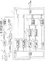
図1は、この発明の実施の形態1に係るレーダ装置を示すブロック構成図である。図1において、このレーダ装置は、ターゲット検出部1、制御電圧発生器2、電圧制御発振器3(VCO:Voltage Controlled Oscillator、以下「VCO3」と称する)、分配器4、送信アンテナ5(送信部)、受信アンテナ6(受信部)、ミキサ7(ミキシング部)、A/Dコンバータ8、および高速フーリエ変換器9(FFT:Fast Fourier Transform、以下「FFT9」と称する)を備えている。
1 is a block diagram showing a radar apparatus according to
ターゲット検出部1は、2つのターゲット21、22までの距離およびターゲット21、22との相対速度を算出し、ターゲット情報として外部装置(図示せず)に出力する。ここで、ターゲット検出部1は、CPU(Central Processing Unit)とプログラムを格納したメモリとを有するマイクロプロセッサ(図示せず)で構成されている。
The
制御電圧発生器2は、ターゲット検出部1の制御下で4つの変調区間を有する制御電圧(詳細については、後述する)を発生し、VCO3に出力する。VCO3は、制御電圧発生器2からの制御電圧に応じて、周波数が時間的に上昇変調および下降変調された送信信号を発生し、分配器4に出力する。分配器4は、VCO3からの送信信号を、送信アンテナ5およびミキサ7に分配して出力する。送信アンテナ5は、分配器4からの送信信号を、送信波W1として空間に放射する。
The control voltage generator 2 generates a control voltage (details will be described later) having four modulation sections under the control of the
受信アンテナ6は、送信波W1がターゲット21、22で反射した反射波W2を受信信号として受信し、ミキサ7に出力する。ミキサ7は、分配器4からの送信信号と受信アンテナ6からの受信信号とをミキシングし、ビート信号を生成して、A/Dコンバータ8に出力する。A/Dコンバータ8は、ミキサ7からのビート信号をアナログ信号からデジタル信号に変換し、FFT9に出力する。FFT9は、A/Dコンバータ8からのデジタル化されたビート信号に対して周波数解析を施し、周波数解析結果(ビート周波数スペクトル)をターゲット検出部1に出力する。
The receiving antenna 6 receives the reflected wave W2 reflected from the targets 21 and 22 as the transmission wave W1 as a received signal and outputs the received signal to the mixer 7. The mixer 7 mixes the transmission signal from the distributor 4 and the reception signal from the reception antenna 6, generates a beat signal, and outputs the beat signal to the A / D converter 8. The A / D converter 8 converts the beat signal from the mixer 7 from an analog signal to a digital signal and outputs it to the FFT 9. The FFT 9 performs frequency analysis on the digitized beat signal from the A / D converter 8 and outputs a frequency analysis result (beat frequency spectrum) to the
続いて、ターゲット検出部1の詳細な構成について説明する。
ターゲット検出部1は、ピーク周波数抽出部10、第1ペア距離・相対速度算出部11、第2ペア距離・相対速度算出部12、ターゲット確定部13、今回ターゲット距離・相対速度推定部14、第1ペアピーク周波数推定部15、第2ペアピーク周波数推定部16、第1ペアピーク調査部17、第2ペアピーク調査部18、およびターゲット距離・相対速度算出部19を有している。ここで、今回ターゲット距離・相対速度推定部14、第1ペアピーク周波数推定部15、第2ペアピーク周波数推定部16、第1ペアピーク調査部17、第2ペアピーク調査部18、およびターゲット距離・相対速度算出部19は、ターゲット推定部20を構成している。
Next, a detailed configuration of the
The
ピーク周波数抽出部10は、FFT9からのビート信号の周波数解析結果に基づいて、ピーク周波数を抽出する。第1ペア距離・相対速度算出部11は、4つの変調区間のうち2つの変調区間のピーク周波数{fu1,fd1}をペアリングして第1ペアを生成し、第1ペアの距離R1および相対速度V1をそれぞれ算出して、ターゲット確定部13に出力する。第2ペア距離・相対速度算出部12は、上記2つの変調区間とは異なる2つの変調区間のピーク周波数{fu2,fd2}をペアリングして第2ペアを生成し、第2ペアの距離R2および相対速度V2をそれぞれ算出して、ターゲット確定部13に出力する。
The peak frequency extraction unit 10 extracts the peak frequency based on the frequency analysis result of the beat signal from the FFT 9. The first pair distance / relative
ターゲット確定部13は、第1ペア距離・相対速度算出部11で算出された第1ペアの距離R1および相対速度V1と、第2ペア距離・相対速度算出部12で算出された第2ペアの距離R2および相対速度V2とがそれぞれほぼ等しい場合に、ターゲット21、22までの距離Rおよびターゲット21、22との相対速度Vを確定し、ターゲット情報として外部装置に出力する。
The target determination unit 13 includes the first pair distance R1 and the relative speed V1 calculated by the first pair distance / relative
今回ターゲット距離・相対速度推定部14は、ターゲット確定部13において前回のサイクルで確定されたターゲット21、22までの距離ROおよびターゲット21、22との相対速度VOに基づいて、線形予測法を用いて、今回の距離REおよび相対速度VEをそれぞれ推定する。 The target distance / relative speed estimation unit 14 uses the linear prediction method based on the distance RO to the targets 21 and 22 and the relative speed VO with the targets 21 and 22 determined in the previous cycle in the target determination unit 13. Thus, the current distance RE and the relative speed VE are estimated.
第1ペアピーク周波数推定部15は、今回ターゲット距離・相対速度推定部14で推定された距離REおよび相対速度VEに基づいて、第1ペアの2つのピーク周波数{fue1,fde1}を推定する。第2ペアピーク周波数推定部16は、今回ターゲット距離・相対速度推定部14で推定された距離REおよび相対速度VEに基づいて、第2ペアの2つのピーク周波数{fue2,fde2}を推定する。
The first pair peak
第1ペアピーク調査部17は、第1ペアピーク周波数推定部15で推定された第1ペアの2つのピーク周波数{fue1,fde1}が、ピーク周波数抽出部10でピーク周波数として抽出されているか否かを調査する。第2ペアピーク調査部18は、第2ペアピーク周波数推定部16で推定された第2ペアの2つのピーク周波数{fue2,fde2}が、ピーク周波数抽出部10でピーク周波数として抽出されているか否かを調査する。
The first pair
ターゲット距離・相対速度算出部19は、第1ペアピーク調査部17および第2ペアピーク調査部18において、第1ペアの2つのピーク周波数がピーク周波数として抽出され、第2ペアの一方のピーク周波数がピーク周波数として抽出され、第2ペアの他方のピーク周波数がピーク周波数として抽出されていないという調査結果が得られた場合に、第1ペアの2つのピーク周波数に基づいて、距離RNおよび相対速度VNを算出する。
The target distance / relative speed calculation unit 19 extracts the two peak frequencies of the first pair as the peak frequencies in the first pair
このとき、ターゲット確定部13は、ターゲット距離・相対速度算出部19で算出された距離RNおよび相対速度VNを、ターゲット21、22までの距離Rおよびターゲット21、22との相対速度Vと確定する。 At this time, the target determination unit 13 determines the distance RN and the relative speed VN calculated by the target distance / relative speed calculation unit 19 as the distance R to the targets 21 and 22 and the relative speed V with respect to the targets 21 and 22. .
なお、ターゲット距離・相対速度算出部19は、第1ペアピーク調査部17および第2ペアピーク調査部18において、第2ペアの2つのピーク周波数がピーク周波数として抽出され、第1ペアの一方のピーク周波数がピーク周波数として抽出され、第1ペアの他方のピーク周波数がピーク周波数として抽出されていないという調査結果が得られた場合に、第2ペアの2つのピーク周波数に基づいて、距離RNおよび相対速度VNを算出する。
The target distance / relative velocity calculation unit 19 extracts the two peak frequencies of the second pair as the peak frequencies in the first pair
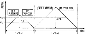
以下、図1、2を参照しながら、この発明の実施の形態1に係るレーダ装置の動作について説明する。図2は、この発明の実施の形態1に係るレーダ装置における4つの変調区間を有する送信信号(制御電圧)の波形を例示する説明図である。
The operation of the radar apparatus according to
まず、ターゲット検出部1から制御電圧発生器2に対して変調開始命令が出力されると、制御電圧発生器2から、図2に示されるような、あらかじめ設定された4つの変調区間(例えば、三角状の第1上昇区間、第1下降区間、第2上昇区間および第2下降区間)を有する制御電圧が発生される。制御電圧発生器2で発生された制御電圧は、VCO3に入力され、VCO3からは、制御電圧に応じて変調区間毎に周波数変調された、4つの変調区間を有する送信信号が出力される。
First, when a modulation start command is output from the
ここで、第1上昇区間および第1下降区間と第2上昇区間および第2下降区間とでは、繰り返し周波数fm、変調幅ΔFおよび中心周波数f0が互いに異なる送信信号がVCO3から出力される。すなわち、第1上昇区間および第1下降区間では、繰り返し周波数fm1、変調幅△F1および中心周波数f0_1の送信信号が出力され、第2上昇区間および第2下降区間では、繰り返し周波数fm2、変調幅△F2および中心周波数f0_2の送信信号が出力される。 Here, in the first rising section, the first falling section, the second rising section, and the second falling section, transmission signals having different repetition frequencies fm, modulation width ΔF, and center frequency f0 are output from the VCO 3. That is, a transmission signal having a repetition frequency fm1, a modulation width ΔF1, and a center frequency f0_1 is output in the first rising interval and the first falling interval, and a repetition frequency fm2 and a modulation width Δ in the second rising interval and the second falling interval. A transmission signal of F2 and center frequency f0_2 is output.
VCO3からの送信信号は、分配器4において、送信アンテナ5およびミキサ7に分配して出力される。送信アンテナ5に出力された送信信号は、送信波W1として空間に放射される。続いて、送信波W1がターゲット21、22で反射した反射波W2は、受信アンテナ6により受信信号として受信され、ミキサ7に出力される。ミキサ7に入力された受信信号は、分配器4からの送信信号とミキシングされてビート信号が生成され、A/Dコンバータ8に出力される。
A transmission signal from the VCO 3 is distributed and output to the
ミキサ7からのビート信号は、A/Dコンバータ8において、第1上昇区間、第1下降区間、第2上昇区間および第2下降区間のそれぞれについて、アナログ信号からデジタル信号に変換され、FFT9に出力される。A/Dコンバータ8からのデジタル化されたビート信号は、FFT9において、高速フーリエ変換を用いた周波数解析が施される。FFT9により算出された周波数解析結果(ビート周波数スペクトル)は、第1上昇区間、第1下降区間、第2上昇区間および第2下降区間のそれぞれについて、ターゲット検出部1に出力される。
In the A / D converter 8, the beat signal from the mixer 7 is converted from an analog signal to a digital signal for each of the first rising interval, the first falling interval, the second rising interval, and the second falling interval, and is output to the FFT 9 Is done. The digitized beat signal from the A / D converter 8 is subjected to frequency analysis using fast Fourier transform in the FFT 9. The frequency analysis result (beat frequency spectrum) calculated by the FFT 9 is output to the
ターゲット検出部1内では、まず、ピーク周波数抽出部10において、FFT9からのビート信号の周波数解析結果に基づいて、ピーク周波数が抽出される。続いて、第1ペア距離・相対速度算出部11において、ピーク周波数抽出部10で抽出された第1上昇区間および第1下降区間のピーク周波数{fu1,fd1}が第1ペアとしてペアリングされ、第1ペアの距離R1および相対速度V1がそれぞれ算出される。また、第2ペア距離・相対速度算出部12において、ピーク周波数抽出部10で抽出された第2上昇区間および第2下降区間のピーク周波数{fu2,fd2}が第2ペアとしてペアリングされ、第2ペアの距離R2および相対速度V2がそれぞれ算出される。
In the
次に、ターゲット確定部13において、第1ペア距離・相対速度算出部11で算出された第1ペアの距離R1および相対速度V1と、第2ペア距離・相対速度算出部12で算出された第2ペアの距離R2および相対速度V2とがそれぞれほぼ等しい場合には、ターゲット21、22までの距離Rおよびターゲット21、22との相対速度Vが確定され、ターゲット情報として外部装置に出力される。
Next, in the target determination unit 13, the first pair distance R1 and the relative speed V1 calculated by the first pair distance / relative
このとき、今回ターゲット距離・相対速度推定部14では、ターゲット確定部13において前回のサイクルで確定されたターゲット21、22までの距離ROおよびターゲット21、22との相対速度VOに基づいて、線形予測法を用いて、今回の距離REおよび相対速度VEがそれぞれ推定される。 At this time, the current target distance / relative speed estimation unit 14 performs linear prediction based on the distance RO to the targets 21 and 22 determined in the previous cycle in the target determination unit 13 and the relative speed VO with the targets 21 and 22. Using this method, the current distance RE and the relative velocity VE are estimated.
続いて、第1ペアピーク周波数推定部15において、今回ターゲット距離・相対速度推定部14で推定された距離REおよび相対速度VEに基づいて、第1ペアの2つのピーク周波数{fue1,fde1}が推定される。また、第2ペアピーク周波数推定部16において、今回ターゲット距離・相対速度推定部14で推定された距離REおよび相対速度VEに基づいて、第2ペアの2つのピーク周波数{fue2,fde2}が推定される。
Subsequently, the first pair peak
次に、第1ペアピーク調査部17において、第1ペアピーク周波数推定部15で推定された第1ペアの2つのピーク周波数{fue1,fde1}が、ピーク周波数抽出部10でピーク周波数として抽出されているか否かが調査される。また、第2ペアピーク調査部18において、第2ペアピーク周波数推定部16で推定された第2ペアの2つのピーク周波数{fue2,fde2}が、ピーク周波数抽出部10でピーク周波数として抽出されているか否かが調査される。
Next, in the first pair
続いて、ターゲット距離・相対速度算出部19では、第1ペアピーク調査部17および第2ペアピーク調査部18において、第1ペアの2つのピーク周波数がピーク周波数として抽出され、第2ペアの一方のピーク周波数がピーク周波数として抽出され、第2ペアの他方のピーク周波数がピーク周波数として抽出されていないという調査結果が得られた場合に、第1ペアのピーク周波数に基づいて、距離RNおよび相対速度VNが算出される。
Subsequently, in the target distance / relative velocity calculation unit 19, the first pair
このとき、ターゲット確定部13において、ターゲット距離・相対速度算出部19で算出された距離RNおよび相対速度VNが、ターゲット21、22までの距離Rおよびターゲット21、22との相対速度Vと確定される。 At this time, the target determination unit 13 determines the distance RN and the relative speed VN calculated by the target distance / relative speed calculation unit 19 as the distance R to the targets 21 and 22 and the relative speed V with respect to the targets 21 and 22. The
なお、ターゲット距離・相対速度算出部19では、第1ペアピーク調査部17および第2ペアピーク調査部18において、第2ペアの2つのピーク周波数がピーク周波数として抽出され、第1ペアの一方のピーク周波数がピーク周波数として抽出され、第1ペアの他方のピーク周波数がピーク周波数として抽出されていないという調査結果が得られた場合に、第2ペアのピーク周波数に基づいて、距離RNおよび相対速度VNが算出される。
In the target distance / relative speed calculation unit 19, the first pair
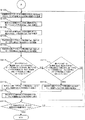
以下、図3、4のフローチャートを参照しながら、この発明の実施の形態1に係るレーダ装置におけるターゲット検出部1の動作について詳細に説明する。なお、この説明において、ターゲット21についての値には添え字aを付し、ターゲット22についての値には添え字bを付すこととする。
Hereinafter, the operation of the
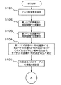
まず、ピーク周波数抽出部10は、FFT9からのビート信号の周波数解析結果(ビート周波数スペクトル)に基づいて、ピーク周波数を抽出する(ステップS101)。具体的には、ピーク周波数抽出部10は、ビート周波数スペクトルの振幅に対して検出閾値を設定し、振幅が検出閾値以上であり、かつ振幅が前後のビート周波数スペクトルよりも大きなビート周波数スペクトルのビート周波数を、ピーク周波数として抽出する。 First, the peak frequency extraction unit 10 extracts a peak frequency based on the frequency analysis result (beat frequency spectrum) of the beat signal from the FFT 9 (step S101). Specifically, the peak frequency extraction unit 10 sets a detection threshold for the amplitude of the beat frequency spectrum, and the beat of the beat frequency spectrum whose amplitude is equal to or larger than the detection threshold and whose amplitude is larger than the preceding and following beat frequency spectra. The frequency is extracted as a peak frequency.
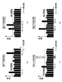
ここで、図5を参照しながら、ピーク周波数抽出部10でのピーク周波数の抽出処理についてさらに説明する。図5(a)は、第1上昇区間のビート周波数スペクトルを示し、図5(b)は、第1下降区間のビート周波数スペクトルを示し、図5(c)は、第2上昇区間のビート周波数スペクトルを示し、図5(d)は、第2下降区間のビート周波数スペクトルを示し、図5(a)〜(d)の横軸および縦軸は、それぞれビート周波数および振幅を示す。 Here, the peak frequency extraction processing in the peak frequency extraction unit 10 will be further described with reference to FIG. 5A shows the beat frequency spectrum in the first rising section, FIG. 5B shows the beat frequency spectrum in the first falling section, and FIG. 5C shows the beat frequency in the second rising section. 5 (d) shows the beat frequency spectrum in the second descending section, and the horizontal and vertical axes in FIGS. 5 (a) to 5 (d) show the beat frequency and amplitude, respectively.
図5において、ピーク周波数抽出部10は、第1上昇区間においてピーク周波数「fu1_a,fu1_b」を抽出し、第1下降区間において「fd1_a,fd1_b」を抽出し、第2上昇区間において「fu2_b」を抽出し、第2下降区間において「fd2_a,fd2_b」を抽出する。なお、図5は、第2上昇区間において、ターゲット21についてのピーク周波数を抽出できなかった場合を例示している。 In FIG. 5, the peak frequency extraction unit 10 extracts the peak frequencies “fu1_a, fu1_b” in the first rising section, extracts “fd1_a, fd1_b” in the first falling section, and “fu2_b” in the second rising section. Extract “fd2_a, fd2_b” in the second descending section. FIG. 5 illustrates a case where the peak frequency for the target 21 cannot be extracted in the second rising section.
図3に戻って、第1ペア距離・相対速度算出部11は、ステップS101で抽出された第1上昇区間および第1下降区間のピーク周波数{fu1,fd1}をペアリングして第1ペアを生成し、第1ペアの距離R1および相対速度V1をそれぞれ算出する(ステップS102)。このとき、第1ペア距離・相対速度算出部11は、一般的なFM−CWレーダの原理に基づいて、すなわち上記式(7)、(8)を用いて、ピーク周波数{fu1,fd1}から第1ペアの距離R1および相対速度V1をそれぞれ算出する。
Returning to FIG. 3, the first pair distance / relative
図5の例では、第1ペア距離・相対速度算出部11は、第1ペアの2つのピーク周波数{fu1_a,fd1_a}から距離R1_aaおよび相対速度V1_aaを算出し、第1ペアの2つのピーク周波数{fu1_a,fd1_b}から距離R1_abおよび相対速度V1_abを算出し、第1ペアの2つのピーク周波数{fu1_b,fd1_a}から距離R1_baおよび相対速度V1_baを算出し、第1ペアの2つのピーク周波数{fu1_b,fd1_b}から距離R1_bbおよび相対速度V1_bbを算出する。
In the example of FIG. 5, the first pair distance /
続いて、第2ペア距離・相対速度算出部12は、ステップS101で抽出された第2上昇区間および第2下降区間のピーク周波数{fu2,fd2}をペアリングして第2ペアを生成し、第2ペアの距離R2および相対速度V2をそれぞれ算出する(ステップS103)。このとき、第2ペア距離・相対速度算出部12は、一般的なFM−CWレーダの原理に基づいて、すなわち上記式(7)、(8)を用いて、ピーク周波数{fu2,fd2}から第2ペアの距離R2および相対速度V2をそれぞれ算出する。 Subsequently, the second pair distance / relative speed calculation unit 12 generates a second pair by pairing the peak frequencies {fu2, fd2} of the second rising section and the second falling section extracted in step S101, The distance R2 and the relative speed V2 of the second pair are calculated (step S103). At this time, the second pair distance / relative velocity calculation unit 12 calculates the peak frequency {fu2, fd2} based on the principle of general FM-CW radar, that is, using the above formulas (7) and (8). The distance R2 and the relative speed V2 of the second pair are calculated.
図5の例では、第2ペア距離・相対速度算出部12は、第2ペアの2つのピーク周波数{fu2_b,fd2_a}から距離R2_baおよび相対速度V2_baを算出し、第2ペアの2つのピーク周波数{fu2_b,fd2_b}から距離R2_bbおよび相対速度V2_bbを算出する。 In the example of FIG. 5, the second pair distance / relative speed calculator 12 calculates the distance R2_ba and the relative speed V2_ba from the two peak frequencies {fu2_b, fd2_a} of the second pair, and the two peak frequencies of the second pair. The distance R2_bb and the relative speed V2_bb are calculated from {fu2_b, fd2_b}.
次に、ターゲット確定部13は、第1ペア距離・相対速度算出部11で算出された第1ペアの距離R1および相対速度V1と、第2ペア距離・相対速度算出部12で算出された第2ペアの距離R2および相対速度V2とが、それぞれほぼ等しい組み合わせを、ターゲット21、22までの距離Rおよびターゲット21、22との相対速度Vとして確定する(ステップS104)。
Next, the target determination unit 13 calculates the first pair distance R1 and relative speed V1 calculated by the first pair distance / relative
なお、ターゲット確定部13は、ターゲット21、22までの距離Rを、第1ペアの距離R1と第2ペアの距離R2との平均とし、ターゲット21、22との相対速度Vを、第1ペアの相対速度V1と第2ペアの相対速度V2との平均としてもよいし、第1ペアおよび第2ペアの何れかの距離および相対速度としてもよい。 The target determination unit 13 sets the distance R to the targets 21 and 22 as an average of the distance R1 of the first pair and the distance R2 of the second pair, and sets the relative speed V to the targets 21 and 22 as the first pair. The relative speed V1 of the second pair and the relative speed V2 of the second pair may be averaged, or may be the distance and the relative speed of either the first pair or the second pair.
図5の例では、第1ペア距離・相対速度算出部11が、第1ペアの距離R1_aaおよび相対速度V1_aa、距離R1_abおよび相対速度V1_ab、距離R1_baおよび相対速度V1_ba、並びに距離R1_bbおよび相対速度V1_bbを算出し、第2ペア距離・相対速度算出部12が、第2ペアの距離R2_baおよび相対速度V2_ba、並びに距離R2_bbおよび相対速度V2_bbを算出している。
In the example of FIG. 5, the first pair distance / relative
このとき、ターゲット確定部13は、ターゲット22についての第1ペアの距離R1_bbおよび相対速度V1_bbと、ターゲット22についての第2ペアの距離R2_bbおよび相対速度V2_bbとが、それぞれほぼ等しいので、これらをターゲット22までの距離R_bおよびターゲット22との相対速度V_bとして確定する。 At this time, since the first pair distance R1_bb and relative speed V1_bb for the target 22 and the second pair distance R2_bb and relative speed V2_bb for the target 22 are substantially equal to each other, the target determination unit 13 uses these as targets. The distance R_b to 22 and the relative speed V_b with the target 22 are determined.
しかしながら、ターゲット確定部13は、ターゲット21についての第1ペアの距離R1_aaおよび相対速度V1_aaと距離および相対速度のほぼ等しい第2ペアが存在しないので、ターゲット21までの距離R_aおよびターゲット21との相対速度V_aを確定することができない。これは、第2上昇区間において、ターゲット21についてのピーク周波数「fu2_a」を抽出できなかったので、第2ペアの距離R2_aaおよび相対速度V2_aaが算出できないからである。 However, the target determination unit 13 does not have a second pair in which the distance R1_aa and the relative speed V1_aa of the first pair are substantially equal to the distance R1_aa and the relative speed V1_aa. The speed V_a cannot be determined. This is because the second pair of distances R2_aa and relative speed V2_aa cannot be calculated because the peak frequency “fu2_a” for the target 21 could not be extracted in the second rising period.
したがって、第1ペアの距離R1_aaおよび相対速度V1_aa、第1ペアの距離R1_abおよび相対速度V1_ab、第1ペアの距離R1_baおよび相対速度V1_ba、並びに第2ペアの距離R2_baおよび相対速度V2_baは、距離および相対速度のほぼ等しいペアが存在しないので、従来は誤ペアリングとして除外される。 Therefore, the first pair distance R1_aa and relative speed V1_aa, the first pair distance R1_ab and relative speed V1_ab, the first pair distance R1_ba and relative speed V1_ba, and the second pair distance R2_ba and relative speed V2_ba are the distance and Conventionally, it is excluded as a false pairing because there is no pair having almost the same relative speed.
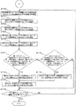
続いて、今回ターゲット距離・相対速度推定部14は、ターゲット確定部13において前回のサイクルで確定されたターゲットの個数Nをカウントして記憶する(ステップS105)。図5の例では、前回確定したターゲットの個数Nは、「2」とする。 Subsequently, the current target distance / relative speed estimation unit 14 counts and stores the number N of targets determined in the previous cycle in the target determination unit 13 (step S105). In the example of FIG. 5, the target number N determined last time is “2”.
次に、今回ターゲット距離・相対速度推定部14は、ターゲット確定部13において前回確定されたターゲット21、22までの距離ROおよびターゲット21、22との相対速度VOに基づいて、一般的な線形予測法である次式(13)、(14)を用いて、今回の距離REおよび相対速度VEをそれぞれ推定する(ステップS106)。なお、式(13)、(14)において、Δtは前回から今回までの処理時間を示し、相対速度VOは接近方向が+を示す。 Next, the current target distance / relative speed estimation unit 14 performs general linear prediction based on the distance RO to the targets 21 and 22 previously determined by the target determination unit 13 and the relative speed VO with the targets 21 and 22. Using the following equations (13) and (14), which are modulo, the current distance RE and relative velocity VE are estimated (step S106). In the equations (13) and (14), Δt indicates the processing time from the previous time to the current time, and the relative speed VO indicates that the approach direction is +.
RE=RO−VO・Δt ・・・(13)
VE=VO ・・・(14)
RE = RO−VO · Δt (13)
VE = VO (14)
図5の例では、今回ターゲット距離・相対速度推定部14は、前回確定されたターゲット21についての距離RO_aaおよび相対速度VO_aaと、ターゲット22についての距離RO_bbおよび相対速度VO_bbとに基づいて、ターゲット21についての今回の距離RE_aaおよび相対速度VE_aaと、ターゲット22についての今回の距離RE_bbおよび相対速度VE_bbとを推定する。 In the example of FIG. 5, the target distance / relative speed estimation unit 14 this time is based on the distance RO_aa and the relative speed VO_aa for the target 21 that was previously determined, and the distance RO_bb and the relative speed VO_bb for the target 22. Current distance RE_aa and relative speed VE_aa for, and current distance RE_bb and relative speed VE_bb for target 22 are estimated.
続いて、第1ペアピーク周波数推定部15は、今回ターゲット距離・相対速度推定部14で推定された距離REおよび相対速度VEに基づいて、第1ペアの2つのピーク周波数{fue1,fde1}を推定する(ステップS107)。すなわち、第1ペアピーク周波数推定部15は、推定された距離REおよび相対速度VEに基づいて、上記式(11)、(12)を用いて、第1上昇区間および第1下降区間のピーク周波数{fue1,fde1}を推定する。
Subsequently, the first pair peak
図5の例では、第1ペアピーク周波数推定部15は、今回ターゲット距離・相対速度推定部14で推定されたターゲット21についての距離RE_aaおよび相対速度VE_aaに基づいて、第1ペアの2つのピーク周波数{fue1_a,fde1_a}を推定する。また、第1ペアピーク周波数推定部15は、今回ターゲット距離・相対速度推定部14で推定されたターゲット22についての距離RE_bbおよび相対速度VE_bbに基づいて、第1ペアの2つのピーク周波数{fue1_b,fde1_b}を推定する。
In the example of FIG. 5, the first pair peak
次に、第2ペアピーク周波数推定部16は、今回ターゲット距離・相対速度推定部14で推定された距離REおよび相対速度VEに基づいて、第2ペアの2つのピーク周波数{fue2,fde2}を推定する(ステップS108)。すなわち、第2ペアピーク周波数推定部16は、推定された距離REおよび相対速度VEに基づいて、上記式(11)、(12)を用いて、第2上昇区間および第2下降区間のピーク周波数{fue2,fde2}を推定する。
Next, the second pair peak
図5の例では、第2ペアピーク周波数推定部16は、今回ターゲット距離・相対速度推定部14で推定されたターゲット22についての距離RE_aaおよび相対速度VE_aaに基づいて、第2ペアの2つのピーク周波数{fue2_a,fde2_a}を推定する。また、第2ペアピーク周波数推定部16は、今回ターゲット距離・相対速度推定部14で推定されたターゲット22についての距離RE_bbおよび相対速度VE_bbに基づいて、第2ペアの2つのピーク周波数{fue2_b,fde2_b}を推定する。
In the example of FIG. 5, the second pair peak
続いて、第1ペアピーク調査部17は、第1ペアピーク周波数推定部15で推定された第1ペアの2つのピーク周波数{fue1,fde1}が、それぞれピーク周波数抽出部10でピーク周波数として抽出されているか否かを調査する(ステップS109)。具体的には、第1ペアピーク調査部17は、第1ペアピーク周波数推定部15で推定されたピーク周波数{fue1,fde1}と、ピーク周波数抽出部10で抽出されたピーク周波数との差が所定範囲内(例えば0)である場合に、ピーク周波数として抽出されていると判定する。
Subsequently, the first pair
図5の例では、第1ペアピーク周波数推定部15で推定されたターゲット21についての第1ペアの2つのピーク周波数{fue1_a,fde1_a}は、ピーク周波数抽出部10によって両方がピーク周波数{fu1_a,fd1_a}として抽出されている。また、第1ペアピーク周波数推定部15で推定されたターゲット22についての第1ペアの2つのピーク周波数{fue1_b,fde1_b}は、ピーク周波数抽出部10によって両方がピーク周波数{fu1_b,fd1_b}として抽出されている。
In the example of FIG. 5, two peak frequencies {fue1_a, fde1_a} of the first pair for the target 21 estimated by the first pair peak
次に、第2ペアピーク調査部18は、第2ペアピーク周波数推定部16で推定された第2ペアの2つのピーク周波数{fue2,fde2}が、それぞれピーク周波数抽出部10でピーク周波数として抽出されているか否かを調査する(ステップS110)。具体的には、第2ペアピーク調査部18は、第2ペアピーク周波数推定部16で推定されたピーク周波数{fue2,fde2}と、ピーク周波数抽出部10で抽出されたピーク周波数との差が所定範囲内(例えば0)である場合に、ピーク周波数として抽出されていると判定する。
Next, the second pair
図5の例では、第2ペアピーク周波数推定部16で推定されたターゲット21についての第2ペアの2つのピーク周波数{fue2_a,fde2_a}は、ピーク周波数抽出部10によって一方のみがピーク周波数{fd2_a}として抽出されている。また、第2ペアピーク周波数推定部16で推定されたターゲット22についての第2ペアの2つのピーク周波数{fue2_b,fde2_b}は、ピーク周波数抽出部10によって両方がピーク周波数{fu2_b,fd2_b}として抽出されている。
In the example of FIG. 5, only one of the two peak frequencies {fue2_a, fde2_a} of the second pair for the target 21 estimated by the second pair peak
続いて、ターゲット距離・相対速度算出部19は、第1ペアの2つのピーク周波数{fue1,fde1}の両方が、それぞれピーク周波数抽出部10でピーク周波数として抽出され、第2ペアの2つのピーク周波数{fue2,fde2}の一方のみが、ピーク周波数抽出部10でピーク周波数として抽出されているか否かを判定する(ステップS111)。 Subsequently, the target distance / relative velocity calculation unit 19 extracts both of the two peak frequencies {fue1, fde1} of the first pair as the peak frequencies by the peak frequency extraction unit 10, respectively. It is determined whether only one of the frequencies {fue2, fde2} has been extracted as a peak frequency by the peak frequency extraction unit 10 (step S111).
ステップS111において、Yesと判定された場合、ターゲット距離・相対速度算出部19は、第1ペアの2つのピーク周波数{fue1,fde1}の両方が、ピーク周波数抽出部10でそれぞれピーク周波数として抽出され、第2ペアの2つのピーク周波数{fue2,fde2}の一方のみが、ピーク周波数抽出部10でピーク周波数として抽出されているので、ピーク周波数抽出部10で抽出された第1ペアの2つのピーク周波数{fu1,fd1}に基づいて、上記式(7)、(8)を用いて、ターゲット21、22までの距離RNおよびターゲット21、22との相対速度VNを算出する(ステップS112)。 When it is determined Yes in step S111, the target distance / relative speed calculation unit 19 extracts both of the two peak frequencies {fue1, fde1} of the first pair as peak frequencies by the peak frequency extraction unit 10, respectively. Since only one of the two peak frequencies {fue2, fde2} of the second pair is extracted as the peak frequency by the peak frequency extraction unit 10, the two peaks of the first pair extracted by the peak frequency extraction unit 10 are extracted. Based on the frequency {fu1, fd1}, the distance RN to the targets 21 and 22 and the relative speed VN with the targets 21 and 22 are calculated using the above formulas (7) and (8) (step S112).
図5の例では、ターゲット21についての第1ペアの2つのピーク周波数{fue1_a,fde1_a}の両方がそれぞれピーク周波数{fu1_a,fd1_a}として抽出され、ターゲット21についての第2ペアの2つのピーク周波数{fue2_a,fde2_a}の一方のみがピーク周波数{fd2_a}として抽出されているので、ターゲット距離・相対速度算出部19は、抽出された第1ペアのピーク周波数{fu1_a,fd1_a}に基づいて、ターゲット21までの距離RN_aおよびターゲット21との相対速度VN_aを算出する。 In the example of FIG. 5, both of the first pair of two peak frequencies {fue1_a, fde1_a} for the target 21 are extracted as peak frequencies {fu1_a, fd1_a}, respectively, and the second pair of two peak frequencies for the target 21 is extracted. Since only one of {fue2_a, fde2_a} is extracted as the peak frequency {fd2_a}, the target distance / relative speed calculation unit 19 determines the target based on the extracted first pair of peak frequencies {fu1_a, fd1_a}. A distance RN_a to 21 and a relative speed VN_a to the target 21 are calculated.
一方、ステップS111において、Noと判定された場合、ターゲット距離・相対速度算出部19は、第2ペアの2つのピーク周波数{fue2,fde2}の両方が、それぞれピーク周波数抽出部10でピーク周波数として抽出され、第1ペアの2つのピーク周波数{fue1,fde1}の一方のみが、ピーク周波数抽出部10でピーク周波数として抽出されているか否かを判定する(ステップS113)。 On the other hand, when it is determined No in step S111, the target distance / relative speed calculation unit 19 determines that both of the two peak frequencies {fue2, fde2} of the second pair are the peak frequencies in the peak frequency extraction unit 10, respectively. It is determined whether or not only one of the two peak frequencies {fue1, fde1} of the first pair is extracted as the peak frequency by the peak frequency extraction unit 10 (step S113).
ステップS113において、Yesと判定された場合、ターゲット距離・相対速度算出部19は、第2ペアの2つのピーク周波数{fue2,fde2}の両方が、ピーク周波数抽出部10でそれぞれピーク周波数として抽出され、第1ペアの2つのピーク周波数{fue1,fde1}の一方のみが、ピーク周波数抽出部10でピーク周波数として抽出されているので、ピーク周波数抽出部10で抽出された第2ペアの2つのピーク周波数{fu2,fd2}に基づいて、上記式(7)、(8)を用いて、ターゲット21、22までの距離RNおよびターゲット21、22との相対速度VNを算出する(ステップS114)。 When it is determined Yes in step S113, the target distance / relative speed calculation unit 19 extracts both of the two peak frequencies {fue2, fde2} of the second pair as peak frequencies by the peak frequency extraction unit 10, respectively. Since only one of the two peak frequencies {fue1, fde1} of the first pair is extracted as the peak frequency by the peak frequency extraction unit 10, the two peaks of the second pair extracted by the peak frequency extraction unit 10 Based on the frequencies {fu2, fd2}, the distance RN to the targets 21 and 22 and the relative speed VN with respect to the targets 21 and 22 are calculated using the above formulas (7) and (8) (step S114).
また、図5の例では、ターゲット22についての第1ペアの2つのピーク周波数{fue1_b,fde1_b}の両方がそれぞれピーク周波数{fu1_b,fd1_b}として抽出され、ターゲット22についての第2ペアの2つのピーク周波数{fue2_b,fde2_b}の両方がそれぞれピーク周波数{fu2_b,fd2_b}として抽出されているので、ステップS113において、Noと判定され、ステップS116(後述する)に移行する。 Further, in the example of FIG. 5, both of the two peak frequencies {fue1_b, fde1_b} of the first pair for the target 22 are extracted as the peak frequencies {fu1_b, fd1_b}, respectively. Since both peak frequencies {fue2_b, fde2_b} are extracted as peak frequencies {fu2_b, fd2_b}, respectively, No is determined in step S113, and the process proceeds to step S116 (described later).
次に、ターゲット確定部13は、ターゲット距離・相対速度算出部19で算出されたターゲット21、22までの距離RNおよびターゲット21、22との相対速度VNを、ターゲット21、22までの距離Rおよびターゲット21、22との相対速度Vと確定する(ステップS115)。図5の例では、ターゲット確定部13は、ターゲット距離・相対速度算出部19で算出されたターゲット21までの距離RN_aおよびターゲット21との相対速度VN_aを、ターゲット21までの距離R_aおよびターゲット21との相対速度V_aとして確定する。 Next, the target determination unit 13 calculates the distance RN to the targets 21 and 22 calculated by the target distance / relative speed calculation unit 19 and the relative speed VN to the targets 21 and 22 from the distance R and the targets 21 and 22. The relative speed V with respect to the targets 21 and 22 is determined (step S115). In the example of FIG. 5, the target determination unit 13 uses the distance RN_a to the target 21 calculated by the target distance / relative speed calculation unit 19 and the relative speed VN_a to the target 21 as the distance R_a to the target 21 and the target 21. Is determined as a relative speed V_a.
続いて、今回ターゲット距離・相対速度推定部14は、ステップS105でカウントした、前回のサイクルで確定されたターゲットの個数N分(図5の例では、「2」個分)の処理が終了したか否かを判定する(ステップS116)。 Subsequently, the target distance / relative speed estimation unit 14 this time finishes the processing for the number N of targets determined in the previous cycle (“2” in the example of FIG. 5) counted in step S105. Is determined (step S116).
ステップS116において、処理が終了した(すなわち、Yes)と判定された場合には、図4の処理を終了する。
一方、ステップS116において、処理が終了していない(すなわち、No)と判定された場合には、ステップS106に戻って、ステップS106〜ステップS116の処理が繰り返し実行される。
If it is determined in step S116 that the process has been completed (that is, Yes), the process in FIG. 4 is terminated.
On the other hand, if it is determined in step S116 that the process has not ended (that is, No), the process returns to step S106, and the processes in steps S106 to S116 are repeatedly executed.
以上のように、実施の形態1によれば、ターゲット推定部は、ビート信号のピーク周波数のうち、少なくとも1つのピーク周波数を抽出することができず、ピーク周波数のペアを生成することができない場合に、ターゲット確定部において前回のサイクルで確定されたターゲットまでの距離およびターゲットとの相対速度に基づいて、ターゲットまでの距離およびターゲットとの相対速度を推定する。
また、ターゲット距離・相対速度算出部は、第1ペアピーク周波数推定部で推定された第1ペアの2つのピーク周波数が、ピーク周波数抽出部でピーク周波数として抽出され、第2ペアピーク周波数推定部で推定された第2ペアの一方のピーク周波数が、ピーク周波数抽出部でピーク周波数として抽出され、第2ペアの他方のピーク周波数がピーク周波数として抽出されていない場合に、第1ペアの2つのピーク周波数に基づいて、ターゲットまでの距離およびターゲットとの相対速度を算出する。
また、ターゲット距離・相対速度算出部は、第2ペアピーク周波数推定部で推定された第2ペアの2つのピーク周波数が、ピーク周波数抽出部でピーク周波数として抽出され、第1ペアピーク周波数推定部で推定された第1ペアの一方のピーク周波数が、ピーク周波数抽出部でピーク周波数として抽出され、第1ペアの他方のピーク周波数がピーク周波数として抽出されていない場合に、第2ペアの2つのピーク周波数に基づいて、ターゲットまでの距離およびターゲットとの相対速度を算出する。
そのため、誤ペアリングの発生を防止するとともに、ビート信号のピーク周波数のうち、少なくとも1つのピーク周波数を抽出することができず、ピーク周波数のペアを生成することができない場合であっても、ターゲットまでの距離およびターゲットとの相対速度を得ることができる。
As described above, according to the first embodiment, the target estimation unit cannot extract at least one peak frequency out of the peak frequencies of the beat signal and cannot generate a pair of peak frequencies. In addition, the distance to the target and the relative speed with respect to the target are estimated based on the distance to the target and the relative speed with the target determined in the previous cycle in the target determination unit.
Further, the target distance / relative velocity calculation unit extracts the two peak frequencies of the first pair estimated by the first pair peak frequency estimation unit as peak frequencies by the peak frequency extraction unit, and estimates by the second pair peak frequency estimation unit. When one peak frequency of the second pair is extracted as a peak frequency by the peak frequency extraction unit and the other peak frequency of the second pair is not extracted as a peak frequency, the two peak frequencies of the first pair are extracted. Based on the above, the distance to the target and the relative speed with the target are calculated.
Further, the target distance / relative velocity calculation unit extracts the two peak frequencies of the second pair estimated by the second pair peak frequency estimation unit as peak frequencies by the peak frequency extraction unit, and estimates them by the first pair peak frequency estimation unit. When one peak frequency of the first pair is extracted as a peak frequency by the peak frequency extraction unit and the other peak frequency of the first pair is not extracted as a peak frequency, the two peak frequencies of the second pair are extracted. Based on the above, the distance to the target and the relative speed with the target are calculated.
Therefore, it is possible to prevent occurrence of erroneous pairing, and at least one of the beat signal peak frequencies cannot be extracted, and even if a pair of peak frequencies cannot be generated, Distance and relative speed with the target.
実施の形態2.
上記実施の形態1では、第1ペアピーク周波数推定部15で推定された第1ペアの2つのピーク周波数および第2ペアピーク周波数推定部16で推定された第2ペアの2つのピーク周波数のうち、何れか1つのピーク周波数がピーク周波数として抽出されていない場合(図5の場合)について説明した。この実施の形態2では、第1ペアの2つのピーク周波数または第2ペアの2つのピーク周波数が、ピーク周波数として抽出されていない場合(図7の場合)について説明する。なお、この発明の実施の形態2に係るレーダ装置を示すブロック構成図は、上記実施の形態1の図1と同様なので、説明を省略する。
Embodiment 2. FIG.
In the first embodiment, any one of the two peak frequencies of the first pair estimated by the first pair peak
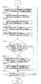
以下、図3、6のフローチャートを参照しながら、この発明の実施の形態2に係るレーダ装置におけるターゲット検出部1の動作について詳細に説明する。なお、この説明において、ターゲット21についての値には添え字aを付し、ターゲット22についての値には添え字bを付すこととする。また、上記実施の形態1と同様の処理については、説明を省略する。
Hereinafter, the operation of the
まず、ピーク周波数抽出部10は、FFT9からのビート信号の周波数解析結果(ビート周波数スペクトル)に基づいて、ピーク周波数を抽出する(ステップS101)。具体的には、ピーク周波数抽出部10は、ビート周波数スペクトルの振幅に対して検出閾値を設定し、振幅が検出閾値以上であり、かつ振幅が前後のビート周波数スペクトルよりも大きなビート周波数スペクトルのビート周波数を、ピーク周波数として抽出する。 First, the peak frequency extraction unit 10 extracts a peak frequency based on the frequency analysis result (beat frequency spectrum) of the beat signal from the FFT 9 (step S101). Specifically, the peak frequency extraction unit 10 sets a detection threshold for the amplitude of the beat frequency spectrum, and the beat of the beat frequency spectrum whose amplitude is equal to or larger than the detection threshold and whose amplitude is larger than the preceding and following beat frequency spectra. The frequency is extracted as a peak frequency.
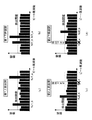
ここで、図7を参照しながら、ピーク周波数抽出部10でのピーク周波数の抽出処理についてさらに説明する。図7(a)は、第1上昇区間のビート周波数スペクトルを示し、図7(b)は、第1下降区間のビート周波数スペクトルを示し、図7(c)は、第2上昇区間のビート周波数スペクトルを示し、図7(d)は、第2下降区間のビート周波数スペクトルを示し、図7(a)〜(d)の横軸および縦軸は、それぞれビート周波数および振幅を示す。 Here, the peak frequency extraction processing in the peak frequency extraction unit 10 will be further described with reference to FIG. 7A shows the beat frequency spectrum in the first rising section, FIG. 7B shows the beat frequency spectrum in the first falling section, and FIG. 7C shows the beat frequency in the second rising section. 7 (d) shows the beat frequency spectrum in the second descending section, and the horizontal and vertical axes in FIGS. 7 (a) to 7 (d) show the beat frequency and amplitude, respectively.
図7において、ピーク周波数抽出部10は、第1上昇区間においてピーク周波数「fu1_a,fu1_b」を抽出し、第1下降区間において「fd1_a,fd1_b」を抽出し、第2上昇区間において「fu2_b」を抽出し、第2下降区間において「fd2_b」を抽出する。なお、図7は、第2上昇区間において、ターゲット21についてのピーク周波数を抽出できず、第2下降区間において、ターゲット21についてのピーク周波数を抽出できなかった場合を例示している。 In FIG. 7, the peak frequency extraction unit 10 extracts the peak frequencies “fu1_a, fu1_b” in the first rising section, extracts “fd1_a, fd1_b” in the first falling section, and “fu2_b” in the second rising section. Extract “fd2_b” in the second descending section. FIG. 7 illustrates a case where the peak frequency for the target 21 cannot be extracted in the second rising section and the peak frequency for the target 21 cannot be extracted in the second falling section.
図3に戻って、ステップS102から図6のステップS108までの処理は、上記実施の形態1と同様なので、説明を省略する。 Returning to FIG. 3, the processing from step S102 to step S108 in FIG. 6 is the same as that in the first embodiment, and the description thereof is omitted.
続いて、第1ペアピーク調査部17は、第1ペアピーク周波数推定部15で推定された第1ペアの2つのピーク周波数{fue1,fde1}が、それぞれピーク周波数抽出部10でピーク周波数として抽出されているか否かを調査する(ステップS109)。具体的には、第1ペアピーク調査部17は、第1ペアピーク周波数推定部15で推定されたピーク周波数{fue1,fde1}と、ピーク周波数抽出部10で抽出されたピーク周波数との差が所定範囲内(例えば0)である場合に、ピーク周波数として抽出されていると判定する。
Subsequently, the first pair
図7の例では、第1ペアピーク周波数推定部15で推定されたターゲット21についての第1ペアの2つのピーク周波数{fue1_a,fde1_a}は、ピーク周波数抽出部10によって両方がピーク周波数{fu1_a,fd1_a}として抽出されている。また、第1ペアピーク周波数推定部15で推定されたターゲット22についての第1ペアの2つのピーク周波数{fue1_b,fde1_b}は、ピーク周波数抽出部10によって両方がピーク周波数{fu1_b,fd1_b}として抽出されている。
In the example of FIG. 7, the two peak frequencies {fue1_a, fde1_a} of the first pair for the target 21 estimated by the first pair peak
次に、第2ペアピーク調査部18は、第2ペアピーク周波数推定部16で推定された第2ペアの2つのピーク周波数{fue2,fde2}が、それぞれピーク周波数抽出部10でピーク周波数として抽出されているか否かを調査する(ステップS110)。具体的には、第2ペアピーク調査部18は、第2ペアピーク周波数推定部16で推定されたピーク周波数{fue2,fde2}と、ピーク周波数抽出部10で抽出されたピーク周波数との差が所定範囲内(例えば0)である場合に、ピーク周波数として抽出されていると判定する。
Next, the second pair
図7の例では、第2ペアピーク周波数推定部16で推定されたターゲット21についての第2ペアの2つのピーク周波数{fue2_a,fde2_a}は、ともにピーク周波数として抽出されていない。また、第2ペアピーク周波数推定部16で推定されたターゲット22についての第2ペアの2つのピーク周波数{fue2_b,fde2_b}は、ピーク周波数抽出部10によって両方がピーク周波数{fu2_b,fd2_b}として抽出されている。
In the example of FIG. 7, the second pair of two peak frequencies {fue2_a, fde2_a} for the target 21 estimated by the second pair peak
続いて、ターゲット距離・相対速度算出部19は、第1ペアの2つのピーク周波数{fue1,fde1}の両方が、それぞれピーク周波数抽出部10でピーク周波数として抽出され、第2ペアの2つのピーク周波数{fue2,fde2}の両方が、ピーク周波数として抽出されていないか否かを判定する(ステップS211)。 Subsequently, the target distance / relative velocity calculation unit 19 extracts both of the two peak frequencies {fue1, fde1} of the first pair as the peak frequencies by the peak frequency extraction unit 10, respectively. It is determined whether or not both of the frequencies {fue2, fde2} are extracted as peak frequencies (step S211).
ステップS211において、Yesと判定された場合、ターゲット距離・相対速度算出部19は、第1ペアの2つのピーク周波数{fue1,fde1}の両方が、ピーク周波数抽出部10でそれぞれピーク周波数として抽出され、第2ペアの2つのピーク周波数{fue2,fde2}の両方が、ピーク周波数として抽出されていないので、ピーク周波数抽出部10で抽出された第1ペアの2つのピーク周波数{fu1,fd1}に基づいて、上記式(7)、(8)を用いて、ターゲット21、22までの距離RNおよびターゲット21、22との相対速度VNを算出する(ステップS112)。 When it is determined Yes in step S211, the target distance / relative speed calculation unit 19 extracts both of the two peak frequencies {fue1, fde1} of the first pair as peak frequencies by the peak frequency extraction unit 10, respectively. Since the two peak frequencies {fue2, fde2} of the second pair are not extracted as peak frequencies, the two peak frequencies {fu1, fd1} of the first pair extracted by the peak frequency extraction unit 10 are used. Based on the above formulas (7) and (8), the distance RN to the targets 21 and 22 and the relative speed VN with respect to the targets 21 and 22 are calculated (step S112).
図7の例では、ターゲット21についての第1ペアの2つのピーク周波数{fue1_a,fde1_a}の両方がそれぞれピーク周波数{fu1_a,fd1_a}として抽出され、ターゲット21についての第2ペアの2つのピーク周波数{fue2_a,fde2_a}の両方がピーク周波数として抽出されていないので、ターゲット距離・相対速度算出部19は、抽出された第1ペアのピーク周波数{fu1_a,fd1_a}に基づいて、ターゲット21までの距離RN_aおよびターゲット21との相対速度VN_aを算出する。 In the example of FIG. 7, both of the first pair of two peak frequencies {fue1_a, fde1_a} for the target 21 are extracted as peak frequencies {fu1_a, fd1_a}, respectively, and the second pair of two peak frequencies for the target 21 is extracted. Since both {fue2_a, fde2_a} are not extracted as peak frequencies, the target distance / relative speed calculation unit 19 determines the distance to the target 21 based on the extracted first pair of peak frequencies {fu1_a, fd1_a}. The relative speed VN_a between RN_a and the target 21 is calculated.
一方、ステップS211において、Noと判定された場合、ターゲット距離・相対速度算出部19は、第2ペアの2つのピーク周波数{fue2,fde2}の両方が、それぞれピーク周波数抽出部10でピーク周波数として抽出され、第1ペアの2つのピーク周波数{fue1,fde1}の両方が、ピーク周波数として抽出されていないか否かを判定する(ステップS213)。 On the other hand, when it is determined No in step S211, the target distance / relative speed calculation unit 19 determines that both of the two peak frequencies {fue2, fde2} of the second pair are peak frequencies in the peak frequency extraction unit 10, respectively. It is determined whether or not both of the two peak frequencies {fue1, fde1} of the first pair are extracted as peak frequencies (step S213).
ステップS213において、Yesと判定された場合、ターゲット距離・相対速度算出部19は、第2ペアの2つのピーク周波数{fue2,fde2}の両方が、ピーク周波数抽出部10でそれぞれピーク周波数として抽出され、第1ペアの2つのピーク周波数{fue1,fde1}の両方が、ピーク周波数として抽出されていないので、ピーク周波数抽出部10で抽出された第2ペアの2つのピーク周波数{fu2,fd2}に基づいて、上記式(7)、(8)を用いて、ターゲット21、22までの距離RNおよびターゲット21、22との相対速度VNを算出する(ステップS114)。 When it is determined as Yes in step S213, the target distance / relative speed calculation unit 19 extracts both of the two peak frequencies {fue2, fde2} of the second pair as peak frequencies by the peak frequency extraction unit 10, respectively. Since the two peak frequencies {fue1, fde1} of the first pair are not extracted as the peak frequencies, the two peak frequencies {fu2, fd2} extracted by the peak frequency extraction unit 10 Based on the above formulas (7) and (8), the distance RN to the targets 21 and 22 and the relative speed VN with respect to the targets 21 and 22 are calculated (step S114).
また、図7の例では、ターゲット22についての第1ペアの2つのピーク周波数{fue1_b,fde1_b}の両方がそれぞれピーク周波数{fu1_b,fd1_b}として抽出され、ターゲット22についての第2ペアの2つのピーク周波数{fue2_b,fde2_b}の両方がそれぞれピーク周波数{fu2_b,fd2_b}として抽出されているので、ステップS213において、Noと判定され、ステップS116に移行する。 In the example of FIG. 7, both of the first pair of two peak frequencies {fue1_b, fde1_b} for the target 22 are extracted as the peak frequencies {fu1_b, fd1_b}, respectively, and two of the second pair for the target 22 are extracted. Since both peak frequencies {fue2_b, fde2_b} are extracted as peak frequencies {fu2_b, fd2_b}, respectively, it is determined No in step S213, and the process proceeds to step S116.
次に、ターゲット確定部13は、ターゲット距離・相対速度算出部19で算出されたターゲット21、22までの距離RNおよびターゲット21、22との相対速度VNを、ターゲット21、22までの距離Rおよびターゲット21、22との相対速度Vと確定する(ステップS115)。図7の例では、ターゲット確定部13は、ターゲット距離・相対速度算出部19で算出されたターゲット21までの距離RN_aおよびターゲット21との相対速度VN_aを、ターゲット21までの距離R_aおよびターゲット21との相対速度V_aとして確定する。 Next, the target determination unit 13 calculates the distance RN to the targets 21 and 22 calculated by the target distance / relative speed calculation unit 19 and the relative speed VN to the targets 21 and 22 from the distance R and the targets 21 and 22. The relative speed V with respect to the targets 21 and 22 is determined (step S115). In the example of FIG. 7, the target determination unit 13 uses the distance RN_a to the target 21 calculated by the target distance / relative speed calculation unit 19 and the relative speed VN_a to the target 21 as the distance R_a to the target 21 and the target 21. Is determined as a relative speed V_a.
続いて、今回ターゲット距離・相対速度推定部14は、ステップS105でカウントした、前回のサイクルで確定されたターゲットの個数N分(図7の例では、「2」個分)の処理が終了したか否かを判定する(ステップS116)。 Subsequently, the current target distance / relative speed estimation unit 14 finishes the processing for the number N of targets determined in the previous cycle (in the example of FIG. 7, “2”) counted in step S105. Is determined (step S116).
ステップS116において、処理が終了した(すなわち、Yes)と判定された場合には、図6の処理を終了する。
一方、ステップS116において、処理が終了していない(すなわち、No)と判定された場合には、ステップS106に戻って、ステップS106〜ステップS116の処理が繰り返し実行される。
If it is determined in step S116 that the process has been completed (that is, Yes), the process in FIG. 6 is terminated.
On the other hand, if it is determined in step S116 that the process has not ended (that is, No), the process returns to step S106, and the processes in steps S106 to S116 are repeatedly executed.
以上のように、実施の形態2によれば、ターゲット推定部は、ビート信号のピーク周波数のうち、少なくとも1つのピーク周波数を抽出することができず、ピーク周波数のペアを生成することができない場合に、ターゲット確定部において前回のサイクルで確定されたターゲットまでの距離およびターゲットとの相対速度に基づいて、ターゲットまでの距離およびターゲットとの相対速度を推定する。
また、ターゲット距離・相対速度算出部は、第1ペアピーク周波数推定部で推定された第1ペアの2つのピーク周波数が、ピーク周波数抽出部でピーク周波数として抽出され、第2ペアピーク周波数推定部で推定された第2ペアの2つのピーク周波数が、ともにピーク周波数として抽出されていない場合に、第1ペアの2つのピーク周波数に基づいて、ターゲットまでの距離およびターゲットとの相対速度を算出する。
また、ターゲット距離・相対速度算出部は、第2ペアピーク周波数推定部で推定された第2ペアの2つのピーク周波数が、ピーク周波数抽出部でピーク周波数として抽出され、第1ペアピーク周波数推定部で推定された第1ペアの2つのピーク周波数が、ともにピーク周波数として抽出されていない場合に、第2ペアの2つのピーク周波数に基づいて、ターゲットまでの距離およびターゲットとの相対速度を算出する。
そのため、誤ペアリングの発生を防止するとともに、ビート信号のピーク周波数のうち、少なくとも1つのピーク周波数を抽出することができず、ピーク周波数のペアを生成することができない場合であっても、ターゲットまでの距離およびターゲットとの相対速度を得ることができる。
As described above, according to the second embodiment, the target estimation unit cannot extract at least one peak frequency among the peak frequencies of the beat signal and cannot generate a pair of peak frequencies. In addition, the distance to the target and the relative speed with respect to the target are estimated based on the distance to the target and the relative speed with the target determined in the previous cycle in the target determination unit.
Further, the target distance / relative velocity calculation unit extracts the two peak frequencies of the first pair estimated by the first pair peak frequency estimation unit as peak frequencies by the peak frequency extraction unit, and estimates by the second pair peak frequency estimation unit. When both of the two peak frequencies of the second pair that have been extracted are not extracted as peak frequencies, the distance to the target and the relative velocity with respect to the target are calculated based on the two peak frequencies of the first pair.
Further, the target distance / relative velocity calculation unit extracts the two peak frequencies of the second pair estimated by the second pair peak frequency estimation unit as peak frequencies by the peak frequency extraction unit, and estimates them by the first pair peak frequency estimation unit. When the two peak frequencies of the first pair that have been extracted are not extracted as peak frequencies, the distance to the target and the relative speed with respect to the target are calculated based on the two peak frequencies of the second pair.
Therefore, it is possible to prevent occurrence of erroneous pairing, and at least one of the beat signal peak frequencies cannot be extracted, and even if a pair of peak frequencies cannot be generated, Distance and relative speed with the target.
実施の形態3.
上記実施の形態1では、第1ペアピーク周波数推定部15で推定された第1ペアの2つのピーク周波数および第2ペアピーク周波数推定部16で推定された第2ペアの2つのピーク周波数のうち、1つのピーク周波数がピーク周波数として抽出されていない場合(図5の場合)について説明した。また、上記実施の形態2では、第1ペアの2つのピーク周波数または第2ペアの2つのピーク周波数が、ピーク周波数として抽出されていない場合(図7の場合)について説明した。
Embodiment 3 FIG.
In the first embodiment, among the two peak frequencies of the first pair estimated by the first pair peak
この実施の形態3では、第1ペアの2つのピーク周波数のうち一方のピーク周波数がピーク周波数として抽出されておらず、第2ペアの2つのピーク周波数のうち一方のピーク周波数がピーク周波数として抽出されていない場合(図9の場合)について説明する。なお、この発明の実施の形態3に係るレーダ装置を示すブロック構成図は、上記実施の形態1の図1と同様なので、説明を省略する。 In the third embodiment, one of the two peak frequencies of the first pair is not extracted as the peak frequency, and one of the two peak frequencies of the second pair is extracted as the peak frequency. A case where it is not performed (in the case of FIG. 9) will be described. The block diagram showing the radar apparatus according to Embodiment 3 of the present invention is the same as that of FIG.
以下、図3、8のフローチャートを参照しながら、この発明の実施の形態3に係るレーダ装置におけるターゲット検出部1の動作について詳細に説明する。なお、この説明において、ターゲット21についての値には添え字aを付し、ターゲット22についての値には添え字bを付すこととする。また、上記実施の形態1と同様の処理については、説明を省略する。
Hereinafter, the operation of the
まず、ピーク周波数抽出部10は、FFT9からのビート信号の周波数解析結果(ビート周波数スペクトル)に基づいて、ピーク周波数を抽出する(ステップS101)。具体的には、ピーク周波数抽出部10は、ビート周波数スペクトルの振幅に対して検出閾値を設定し、振幅が検出閾値以上であり、かつ振幅が前後のビート周波数スペクトルよりも大きなビート周波数スペクトルのビート周波数を、ピーク周波数として抽出する。 First, the peak frequency extraction unit 10 extracts a peak frequency based on the frequency analysis result (beat frequency spectrum) of the beat signal from the FFT 9 (step S101). Specifically, the peak frequency extraction unit 10 sets a detection threshold for the amplitude of the beat frequency spectrum, and the beat of the beat frequency spectrum whose amplitude is equal to or larger than the detection threshold and whose amplitude is larger than the preceding and following beat frequency spectra. The frequency is extracted as a peak frequency.
ここで、図9を参照しながら、ピーク周波数抽出部10でのピーク周波数の抽出処理についてさらに説明する。図9(a)は、第1上昇区間のビート周波数スペクトルを示し、図9(b)は、第1下降区間のビート周波数スペクトルを示し、図9(c)は、第2上昇区間のビート周波数スペクトルを示し、図9(d)は、第2下降区間のビート周波数スペクトルを示し、図9(a)〜(d)の横軸および縦軸は、それぞれビート周波数および振幅を示す。 Here, the peak frequency extraction processing in the peak frequency extraction unit 10 will be further described with reference to FIG. 9A shows the beat frequency spectrum in the first rising section, FIG. 9B shows the beat frequency spectrum in the first falling section, and FIG. 9C shows the beat frequency in the second rising section. 9 (d) shows the beat frequency spectrum in the second descending section, and the horizontal and vertical axes in FIGS. 9 (a) to 9 (d) show the beat frequency and amplitude, respectively.
図9において、ピーク周波数抽出部10は、第1上昇区間においてピーク周波数「fu1_a,fu1_b」を抽出し、第1下降区間において「fd1_b」を抽出し、第2上昇区間において「fu2_b」を抽出し、第2下降区間において「fd2_a,fd2_b」を抽出する。なお、図9は、第1下降区間において、ターゲット21についてのピーク周波数を抽出できず、第2上昇区間において、ターゲット21についてのピーク周波数を抽出できなかった場合を例示している。 In FIG. 9, the peak frequency extraction unit 10 extracts the peak frequencies “fu1_a, fu1_b” in the first rising section, extracts “fd1_b” in the first falling section, and extracts “fu2_b” in the second rising section. In the second descending section, “fd2_a, fd2_b” are extracted. FIG. 9 illustrates a case where the peak frequency for the target 21 cannot be extracted in the first descending section, and the peak frequency for the target 21 cannot be extracted in the second rising section.
図3に戻って、ステップS102から図8のステップS108までの処理は、上記実施の形態1と同様なので、説明を省略する。 Returning to FIG. 3, the processing from step S102 to step S108 in FIG. 8 is the same as that in the first embodiment, and the description thereof is omitted.
続いて、第1ペアピーク調査部17は、第1ペアピーク周波数推定部15で推定された第1ペアの2つのピーク周波数{fue1,fde1}が、それぞれピーク周波数抽出部10でピーク周波数として抽出されているか否かを調査する(ステップS109)。具体的には、第1ペアピーク調査部17は、第1ペアピーク周波数推定部15で推定されたピーク周波数{fue1,fde1}と、ピーク周波数抽出部10で抽出されたピーク周波数との差が所定範囲内(例えば0)である場合に、ピーク周波数として抽出されていると判定する。
Subsequently, the first pair
図9の例では、第1ペアピーク周波数推定部15で推定されたターゲット21についての第1ペアの2つのピーク周波数{fue1_a,fde1_a}は、ピーク周波数抽出部10によって一方のみがピーク周波数{fu1_a}として抽出されている。また、第1ペアピーク周波数推定部15で推定されたターゲット22についての第1ペアの2つのピーク周波数{fue1_b,fde1_b}は、ピーク周波数抽出部10によって両方がピーク周波数{fu1_b,fd1_b}として抽出されている。
In the example of FIG. 9, only one of the two peak frequencies {fue1_a, fde1_a} of the first pair for the target 21 estimated by the first pair peak
次に、第2ペアピーク調査部18は、第2ペアピーク周波数推定部16で推定された第2ペアの2つのピーク周波数{fue2,fde2}が、それぞれピーク周波数抽出部10でピーク周波数として抽出されているか否かを調査する(ステップS110)。具体的には、第2ペアピーク調査部18は、第2ペアピーク周波数推定部16で推定されたピーク周波数{fue2,fde2}と、ピーク周波数抽出部10で抽出されたピーク周波数との差が所定範囲内(例えば0)である場合に、ピーク周波数として抽出されていると判定する。
Next, the second pair
図9の例では、第2ペアピーク周波数推定部16で推定されたターゲット21についての第2ペアの2つのピーク周波数{fue2_a,fde2_a}は、ピーク周波数抽出部10によって一方のみがピーク周波数{fd2_a}として抽出されている。また、第2ペアピーク周波数推定部16で推定されたターゲット22についての第2ペアの2つのピーク周波数{fue2_b,fde2_b}は、ピーク周波数抽出部10によって両方がピーク周波数{fu2_b,fd2_b}として抽出されている。
In the example of FIG. 9, only one of the two peak frequencies {fue2_a, fde2_a} of the second pair for the target 21 estimated by the second pair peak
続いて、ターゲット距離・相対速度算出部19は、第1ペアの2つのピーク周波数{fue1,fde1}の一方のみが、ピーク周波数抽出部10でピーク周波数として抽出され、第2ペアの2つのピーク周波数{fue2,fde2}の一方のみが、ピーク周波数抽出部10でピーク周波数として抽出されているか否かを判定する(ステップS311)。 Subsequently, the target distance / relative velocity calculation unit 19 extracts only one of the two peak frequencies {fue1, fde1} of the first pair as the peak frequency by the peak frequency extraction unit 10, and the two peaks of the second pair. It is determined whether only one of the frequencies {fue2, fde2} has been extracted as a peak frequency by the peak frequency extraction unit 10 (step S311).
ステップS311において、Yesと判定された場合、ターゲット距離・相対速度算出部19は、第1ペアの2つのピーク周波数{fue1,fde1}の一方のみが、ピーク周波数抽出部10でピーク周波数として抽出され、第2ペアの2つのピーク周波数{fue2,fde2}の一方のみが、ピーク周波数抽出部10でピーク周波数として抽出されているので、ピーク周波数抽出部10で抽出された第1ペアの2つのピーク周波数{fu1,fd1}および第2ペアの2つのピーク周波数{fu2,fd2}に基づいて、上記式(9)〜(12)を用いて、ターゲット21、22までの距離RNおよびターゲット21、22との相対速度VNを算出する(ステップS312)。 When it is determined Yes in step S311, the target distance / relative speed calculation unit 19 extracts only one of the two peak frequencies {fue1, fde1} of the first pair as the peak frequency by the peak frequency extraction unit 10. Since only one of the two peak frequencies {fue2, fde2} of the second pair is extracted as the peak frequency by the peak frequency extraction unit 10, the two peaks of the first pair extracted by the peak frequency extraction unit 10 are extracted. Based on the frequency {fu1, fd1} and the second pair of two peak frequencies {fu2, fd2}, using the above formulas (9) to (12), the distance RN to the targets 21, 22 and the targets 21, 22 Relative speed VN is calculated (step S312).
このとき、ターゲット距離・相対速度算出部19は、第1上昇区間および第1下降区間では、繰り返し周波数fm1、変調幅△F1および中心周波数f0_1を用い、第2上昇区間および第2下降区間では、繰り返し周波数fm2、変調幅△F2および中心周波数f0_2を用いる。 At this time, the target distance / relative speed calculation unit 19 uses the repetition frequency fm1, the modulation width ΔF1 and the center frequency f0_1 in the first rising section and the first falling section, and in the second rising section and the second falling section. The repetition frequency fm2, the modulation width ΔF2, and the center frequency f0_2 are used.
図9の例では、ターゲット21についての第1ペアの2つのピーク周波数{fue1_a,fde1_a}の一方のみがピーク周波数{fu1_a}として抽出され、ターゲット21についての第2ペアの2つのピーク周波数{fue2_a,fde2_a}の一方のみがピーク周波数{fd2_a}として抽出されているので、ターゲット距離・相対速度算出部19は、抽出された第1ペアのピーク周波数{fu1_a}と抽出された第2ペアのピーク周波数{fd2_a}に基づいて、ターゲット21までの距離RN_aおよびターゲット21との相対速度VN_aを算出する。 In the example of FIG. 9, only one of the first pair of two peak frequencies {fue1_a, fde1_a} for the target 21 is extracted as the peak frequency {fu1_a}, and the second pair of two peak frequencies {fue2_a} for the target 21. , Fde2_a} is extracted as the peak frequency {fd2_a}, the target distance / relative velocity calculation unit 19 extracts the extracted first pair of peak frequencies {fu1_a} and the extracted second pair of peaks. Based on the frequency {fd2_a}, the distance RN_a to the target 21 and the relative speed VN_a to the target 21 are calculated.
具体的には、ターゲット距離・相対速度算出部19は、上記式(9)〜(12)から次式(15)〜(20)を導き、式(17)、(20)の連立方程式を解くことにより、ターゲット21までの距離RN_aおよびターゲット21との相対速度VN_aを算出する。 Specifically, the target distance / relative speed calculation unit 19 derives the following equations (15) to (20) from the above equations (9) to (12), and solves the simultaneous equations of the equations (17) and (20). Thus, the distance RN_a to the target 21 and the relative speed VN_a to the target 21 are calculated.
M11=C/(4・fm1・ΔF1) ・・・(15)
M21=C/(2・f0_1) ・・・(16)
fu1_a=RN_a/M11−VN_a/M21 ・・・(17)
M12=C/(4・fm2・ΔF2) ・・・(18)
M22=C/(2・f0_2) ・・・(19)
fd2_a=RN_a/M12+VN_a/M22 ・・・(20)
M11 = C / (4 · fm1 · ΔF1) (15)
M21 = C / (2 · f0_1) (16)
fu1_a = RN_a / M11−VN_a / M21 (17)
M12 = C / (4 · fm2 · ΔF2) (18)
M22 = C / (2 · f0_2) (19)
fd2_a = RN_a / M12 + VN_a / M22 (20)
また、図9の例では、ターゲット22についての第1ペアの2つのピーク周波数{fue1_b,fde1_b}の両方がそれぞれピーク周波数{fu1_b,fd1_b}として抽出され、ターゲット22についての第2ペアの2つのピーク周波数{fue2_b,fde2_b}の両方がそれぞれピーク周波数{fu2_b,fd2_b}として抽出されているので、ステップS311において、Noと判定され、ステップS116に移行する。 In the example of FIG. 9, both of the first pair of two peak frequencies {fue1_b, fde1_b} for the target 22 are extracted as the peak frequencies {fu1_b, fd1_b}, respectively, Since both peak frequencies {fue2_b, fde2_b} have been extracted as peak frequencies {fu2_b, fd2_b}, respectively, it is determined No in step S311, and the process proceeds to step S116.
次に、ターゲット確定部13は、ターゲット距離・相対速度算出部19で算出されたターゲット21、22までの距離RNおよびターゲット21、22との相対速度VNを、ターゲット21、22までの距離Rおよびターゲット21、22との相対速度Vと確定する(ステップS115)。図9の例では、ターゲット確定部13は、ターゲット距離・相対速度算出部19で算出されたターゲット21までの距離RN_aおよびターゲット21との相対速度VN_aを、ターゲット21までの距離R_aおよびターゲット21との相対速度V_aとして確定する。 Next, the target determination unit 13 calculates the distance RN to the targets 21 and 22 calculated by the target distance / relative speed calculation unit 19 and the relative speed VN to the targets 21 and 22 from the distance R and the targets 21 and 22. The relative speed V with respect to the targets 21 and 22 is determined (step S115). In the example of FIG. 9, the target determination unit 13 uses the distance RN_a to the target 21 calculated by the target distance / relative speed calculation unit 19 and the relative speed VN_a to the target 21 as the distance R_a to the target 21 and the target 21. Is determined as a relative speed V_a.
続いて、今回ターゲット距離・相対速度推定部14は、ステップS105でカウントした、前回のサイクルで確定されたターゲットの個数N分(図9の例では、「2」個分)の処理が終了したか否かを判定する(ステップS116)。 Subsequently, the current target distance / relative speed estimation unit 14 finishes the processing for the number N of targets determined in the previous cycle (in the example of FIG. 9, “2”) counted in step S105. Is determined (step S116).
ステップS116において、処理が終了した(すなわち、Yes)と判定された場合には、図8の処理を終了する。
一方、ステップS116において、処理が終了していない(すなわち、No)と判定された場合には、ステップS106に戻って、ステップS106〜ステップS116の処理が繰り返し実行される。
If it is determined in step S116 that the process has been completed (that is, Yes), the process in FIG. 8 is terminated.
On the other hand, if it is determined in step S116 that the process has not ended (that is, No), the process returns to step S106, and the processes in steps S106 to S116 are repeatedly executed.
以上のように、実施の形態3によれば、ターゲット推定部は、ビート信号のピーク周波数のうち、少なくとも1つのピーク周波数を抽出することができず、ピーク周波数のペアを生成することができない場合に、ターゲット確定部において前回のサイクルで確定されたターゲットまでの距離およびターゲットとの相対速度に基づいて、ターゲットまでの距離およびターゲットとの相対速度を推定する。
また、ターゲット距離・相対速度算出部は、第1ペアピーク周波数推定部で推定された第1ペアの一方のピーク周波数が、ピーク周波数抽出部でピーク周波数として抽出され、第1ペアの他方のピーク周波数がピーク周波数として抽出されておらず、第2ペアピーク周波数推定部で推定された第2ペアの一方のピーク周波数が、ピーク周波数抽出部でピーク周波数として抽出され、第2ペアの他方のピーク周波数がピーク周波数として抽出されていない場合に、第1ペアの抽出されたピーク周波数と第2ペアの抽出されたピーク周波数とに基づいて、ターゲットまでの距離およびターゲットとの相対速度を算出する。
そのため、誤ペアリングの発生を防止するとともに、ビート信号のピーク周波数のうち、少なくとも1つのピーク周波数を抽出することができず、ピーク周波数のペアを生成することができない場合であっても、ターゲットまでの距離およびターゲットとの相対速度を得ることができる。
As described above, according to the third embodiment, the target estimation unit cannot extract at least one of the peak frequencies of the beat signal and cannot generate a pair of peak frequencies. In addition, the distance to the target and the relative speed with respect to the target are estimated based on the distance to the target and the relative speed with the target determined in the previous cycle in the target determination unit.
Further, the target distance / relative speed calculation unit extracts one peak frequency of the first pair estimated by the first pair peak frequency estimation unit as a peak frequency by the peak frequency extraction unit, and the other peak frequency of the first pair. Is not extracted as a peak frequency, one peak frequency of the second pair estimated by the second pair peak frequency estimation unit is extracted as a peak frequency by the peak frequency extraction unit, and the other peak frequency of the second pair is When not extracted as the peak frequency, the distance to the target and the relative velocity with respect to the target are calculated based on the extracted peak frequency of the first pair and the extracted peak frequency of the second pair.
Therefore, it is possible to prevent occurrence of erroneous pairing, and at least one of the beat signal peak frequencies cannot be extracted, and even if a pair of peak frequencies cannot be generated, Distance and relative speed with the target.
なお、上記実施の形態1〜3では、ターゲット21、22までの距離Rおよびターゲット21、22との相対速度Vを算出する方式として、一般的なFM−CWレーダの原理を用いた方式を示したが、これに限定されず、送信信号をパルス状に区切って変調したFM−パルスドップラーレーダ方式や、その他のレーダ方式を用いてもよい。 In the first to third embodiments, a method using the principle of a general FM-CW radar is shown as a method for calculating the distance R to the targets 21 and 22 and the relative velocity V to the targets 21 and 22. However, the present invention is not limited to this, and an FM-pulse Doppler radar system in which a transmission signal is divided into pulses and modulated, or another radar system may be used.
また、上記実施の形態1〜3では、4つの変調区間として、三角状の第1上昇区間、第1下降区間、第2上昇区間および第2下降区間(第1上昇区間および第1下降区間では、繰り返し周波数fm1、変調幅△F1および中心周波数f0_1、第2上昇区間および第2下降区間では、繰り返し周波数fm2、変調幅△F2および中心周波数f0_2)を用いた場合を示したが、これに限定されない。変調区間は、区間毎に上昇または下降、繰り返し周波数fm、変調幅△Fまたは中心周波数f0が異なってもよいし、4つ以上の複数変調区間を有していてもよい。 In the first to third embodiments, the four modulation sections include a triangular first rising section, a first falling section, a second rising section, and a second falling section (in the first rising section and the first falling section). The repetition frequency fm1, the modulation width ΔF1 and the center frequency f0_1, and the repetition frequency fm2, the modulation width ΔF2 and the center frequency f0_2) are shown in the second rising section and the second falling section. However, the present invention is not limited to this. Not. The modulation period may increase or decrease, the repetition frequency fm, the modulation width ΔF, or the center frequency f0 may be different for each section, or may have four or more modulation sections.
1 ターゲット検出部、2 制御電圧発生器、3 VCO、4 分配器、5 送信アンテナ(送信部)、6 受信アンテナ(受信部)、7 ミキサ(ミキシング部)、8 A/Dコンバータ、9 FFT、10 ピーク周波数抽出部、11 第1ペア距離・相対速度算出部、12 第2ペア距離・相対速度算出部、13 ターゲット確定部、14 今回ターゲット距離・相対速度推定部、15 第1ペアピーク周波数推定部、16 第2ペアピーク周波数推定部、17 第1ペアピーク調査部、18 第2ペアピーク調査部、19 ターゲット距離・相対速度算出部、20 ターゲット推定部、21、22 ターゲット、W1 送信波、W2 反射波。 1 target detection unit, 2 control voltage generator, 3 VCO, 4 distributor, 5 transmission antenna (transmission unit), 6 reception antenna (reception unit), 7 mixer (mixing unit), 8 A / D converter, 9 FFT, DESCRIPTION OF SYMBOLS 10 Peak frequency extraction part, 11 1st pair distance and relative speed calculation part, 12 2nd pair distance and relative speed calculation part, 13 Target determination part, 14 This time target distance and relative speed estimation part, 15 1st pair peak frequency estimation part , 16 Second pair peak frequency estimation unit, 17 First pair peak survey unit, 18 Second pair peak survey unit, 19 Target distance / relative velocity calculation unit, 20 Target estimation unit, 21, 22 Target, W1 transmission wave, W2 reflected wave.
Claims (7)
前記送信波がターゲットで反射した反射波を受信信号として受信する受信部と、
前記送信信号と前記受信信号とをミキシングしてビート信号を生成するミキシング部と、
前記ビート信号に基づいて、前記ターゲットまでの距離および前記ターゲットとの相対速度を算出するターゲット検出部と、を備え、
前記ターゲット検出部は、
周波数解析された前記ビート信号から、前記変調区間の各々におけるピーク周波数を抽出するピーク周波数抽出部と、
前記ピーク周波数抽出部で抽出されたピーク周波数から、前記4つの変調区間のうち2つの変調区間のピーク周波数をペアリングして第1ペアを生成し、前記第1ペアの距離および相対速度をそれぞれ算出する第1ペア距離・相対速度算出部と、
前記ピーク周波数抽出部で抽出されたピーク周波数から、上記2つの変調区間とは異なる2つの変調区間のピーク周波数をペアリングして第2ペアを生成し、前記第2ペアの距離および相対速度をそれぞれ算出する第2ペア距離・相対速度算出部と、
前記第1ペアの距離および相対速度と前記第2ペアの距離および相対速度とがそれぞれ等しい場合に、前記ターゲットまでの距離および前記ターゲットとの相対速度を確定するターゲット確定部と、
前記ビート信号のピーク周波数のうち、少なくとも1つのピーク周波数を抽出することができず、ピーク周波数のペアを生成することができない場合に、前記ターゲット確定部において前回のサイクルで確定された前記ターゲットまでの距離および前記ターゲットとの相対速度に基づいて、前記ターゲットまでの距離および前記ターゲットとの相対速度を推定するターゲット推定部と、を有し、
前記ターゲット推定部は、
前記ターゲット確定部において前回のサイクルで確定された前記ターゲットまでの距離および前記ターゲットとの相対速度に基づいて、線形予測法を用いて、今回の距離および相対速度をそれぞれ推定する今回ターゲット距離・相対速度推定部と、
前記今回ターゲット距離・相対速度推定部で推定された前記今回の距離および相対速度に基づいて、第1ペアの2つのピーク周波数を推定する第1ペアピーク周波数推定部と、
前記今回ターゲット距離・相対速度推定部で推定された前記今回の距離および相対速度に基づいて、第2ペアの2つのピーク周波数を推定する第2ペアピーク周波数推定部と、
前記第1ペアピーク周波数推定部で推定された前記第1ペアの2つのピーク周波数が、前記ピーク周波数抽出部でピーク周波数として抽出されているか否かを調査する第1ペアピーク調査部と、
前記第2ペアピーク周波数推定部で推定された前記第2ペアの2つのピーク周波数が、前記ピーク周波数抽出部でピーク周波数として抽出されているか否かを調査する第2ペアピーク調査部と、
前記第1ペアピーク調査部および前記第2ペアピーク調査部の調査結果により、前記ビート信号のピーク周波数のうち、少なくとも1つのピーク周波数を抽出することができず、ピーク周波数のペアを生成することができない場合に、前記ターゲットまでの距離および前記ターゲットとの相対速度を算出するターゲット距離・相対速度算出部と、を含み、
前記ターゲット距離・相対速度算出部は、
前記第1ペアピーク周波数推定部で推定された前記第1ペアの2つのピーク周波数が、前記ピーク周波数抽出部でピーク周波数として抽出され、
前記第2ペアピーク周波数推定部で推定された前記第2ペアの一方のピーク周波数が、前記ピーク周波数抽出部でピーク周波数として抽出され、前記第2ペアの他方のピーク周波数がピーク周波数として抽出されていない場合に、
前記第1ペアの2つのピーク周波数に基づいて、前記ターゲットまでの距離および前記ターゲットとの相対速度を算出する
ことを特徴とするレーダ装置。 A transmitter that radiates a transmission signal having four modulation sections as a transmission wave;
A receiving unit that receives the reflected wave reflected by the target as a received signal;
A mixing unit that generates a beat signal by mixing the transmission signal and the reception signal;
A target detection unit that calculates a distance to the target and a relative speed with the target based on the beat signal;
The target detection unit
A peak frequency extraction unit for extracting a peak frequency in each of the modulation sections from the beat signal subjected to frequency analysis;
From the peak frequency extracted by the peak frequency extraction unit, pairing the peak frequencies of two modulation intervals among the four modulation intervals to generate a first pair, and the distance and relative velocity of the first pair are respectively determined. A first pair distance / relative speed calculator for calculating;
From the peak frequency extracted by the peak frequency extraction unit, pair the peak frequencies of two modulation sections different from the two modulation sections to generate a second pair, and calculate the distance and relative speed of the second pair. A second pair distance / relative speed calculation unit for calculating each;
A target determination unit for determining a distance to the target and a relative speed with respect to the target when the distance and relative speed of the first pair are equal to the distance and relative speed of the second pair;
If at least one of the peak frequencies of the beat signal cannot be extracted and a pair of peak frequencies cannot be generated, up to the target determined in the previous cycle in the target determination unit based on the distance and the relative speed with the target, we have a, a target estimation unit that estimates a relative speed between the distance and the target until the target,
The target estimator is
Based on the distance to the target determined in the previous cycle in the target determination unit and the relative speed with the target, the current target distance and relative speed are estimated using a linear prediction method, respectively. A speed estimator;
A first pair peak frequency estimation unit that estimates two peak frequencies of the first pair based on the current distance and relative speed estimated by the current target distance / relative speed estimation unit;
A second pair peak frequency estimation unit that estimates two peak frequencies of the second pair based on the current distance and relative speed estimated by the current target distance / relative speed estimation unit;
A first pair peak survey unit that investigates whether or not the two peak frequencies of the first pair estimated by the first pair peak frequency estimation unit are extracted as peak frequencies by the peak frequency extraction unit;
A second pair peak survey unit that investigates whether or not the two peak frequencies of the second pair estimated by the second pair peak frequency estimation unit are extracted as peak frequencies by the peak frequency extraction unit;
According to the investigation results of the first pair peak investigation unit and the second pair peak investigation unit, at least one peak frequency cannot be extracted from the peak frequencies of the beat signal, and a peak frequency pair cannot be generated. A target distance / relative speed calculation unit that calculates a distance to the target and a relative speed with the target, and
The target distance / relative speed calculator is
The two peak frequencies of the first pair estimated by the first pair peak frequency estimation unit are extracted as peak frequencies by the peak frequency extraction unit,
One peak frequency of the second pair estimated by the second pair peak frequency estimation unit is extracted as a peak frequency by the peak frequency extraction unit, and the other peak frequency of the second pair is extracted as a peak frequency. If not,
A radar apparatus , wherein a distance to the target and a relative speed with respect to the target are calculated based on the two peak frequencies of the first pair .
前記送信波がターゲットで反射した反射波を受信信号として受信する受信部と、
前記送信信号と前記受信信号とをミキシングしてビート信号を生成するミキシング部と、
前記ビート信号に基づいて、前記ターゲットまでの距離および前記ターゲットとの相対速度を算出するターゲット検出部と、を備え、
前記ターゲット検出部は、
周波数解析された前記ビート信号から、前記変調区間の各々におけるピーク周波数を抽出するピーク周波数抽出部と、
前記ピーク周波数抽出部で抽出されたピーク周波数から、前記4つの変調区間のうち2つの変調区間のピーク周波数をペアリングして第1ペアを生成し、前記第1ペアの距離および相対速度をそれぞれ算出する第1ペア距離・相対速度算出部と、
前記ピーク周波数抽出部で抽出されたピーク周波数から、上記2つの変調区間とは異なる2つの変調区間のピーク周波数をペアリングして第2ペアを生成し、前記第2ペアの距離および相対速度をそれぞれ算出する第2ペア距離・相対速度算出部と、
前記第1ペアの距離および相対速度と前記第2ペアの距離および相対速度とがそれぞれ等しい場合に、前記ターゲットまでの距離および前記ターゲットとの相対速度を確定するターゲット確定部と、
前記ビート信号のピーク周波数のうち、少なくとも1つのピーク周波数を抽出することができず、ピーク周波数のペアを生成することができない場合に、前記ターゲット確定部において前回のサイクルで確定された前記ターゲットまでの距離および前記ターゲットとの相対速度に基づいて、前記ターゲットまでの距離および前記ターゲットとの相対速度を推定するターゲット推定部と、を有し、
前記ターゲット推定部は、
前記ターゲット確定部において前回のサイクルで確定された前記ターゲットまでの距離および前記ターゲットとの相対速度に基づいて、線形予測法を用いて、今回の距離および相対速度をそれぞれ推定する今回ターゲット距離・相対速度推定部と、
前記今回ターゲット距離・相対速度推定部で推定された前記今回の距離および相対速度に基づいて、第1ペアの2つのピーク周波数を推定する第1ペアピーク周波数推定部と、
前記今回ターゲット距離・相対速度推定部で推定された前記今回の距離および相対速度に基づいて、第2ペアの2つのピーク周波数を推定する第2ペアピーク周波数推定部と、
前記第1ペアピーク周波数推定部で推定された前記第1ペアの2つのピーク周波数が、前記ピーク周波数抽出部でピーク周波数として抽出されているか否かを調査する第1ペアピーク調査部と、
前記第2ペアピーク周波数推定部で推定された前記第2ペアの2つのピーク周波数が、前記ピーク周波数抽出部でピーク周波数として抽出されているか否かを調査する第2ペアピーク調査部と、
前記第1ペアピーク調査部および前記第2ペアピーク調査部の調査結果により、前記ビート信号のピーク周波数のうち、少なくとも1つのピーク周波数を抽出することができず、ピーク周波数のペアを生成することができない場合に、前記ターゲットまでの距離および前記ターゲットとの相対速度を算出するターゲット距離・相対速度算出部と、を含み、
前記ターゲット距離・相対速度算出部は、
前記第2ペアピーク周波数推定部で推定された前記第2ペアの2つのピーク周波数が、前記ピーク周波数抽出部でピーク周波数として抽出され、
前記第1ペアピーク周波数推定部で推定された前記第1ペアの一方のピーク周波数が、前記ピーク周波数抽出部でピーク周波数として抽出され、前記第1ペアの他方のピーク周波数がピーク周波数として抽出されていない場合に、
前記第2ペアの2つのピーク周波数に基づいて、前記ターゲットまでの距離および前記ターゲットとの相対速度を算出する
ことを特徴とするレーダ装置。 A transmitter that radiates a transmission signal having four modulation sections as a transmission wave;
A receiving unit that receives the reflected wave reflected by the target as a received signal;
A mixing unit that generates a beat signal by mixing the transmission signal and the reception signal;
A target detection unit that calculates a distance to the target and a relative speed with the target based on the beat signal;
The target detection unit
A peak frequency extraction unit for extracting a peak frequency in each of the modulation sections from the beat signal subjected to frequency analysis;
From the peak frequency extracted by the peak frequency extraction unit, pairing the peak frequencies of two modulation intervals among the four modulation intervals to generate a first pair, and the distance and relative velocity of the first pair are respectively determined. A first pair distance / relative speed calculator for calculating;
From the peak frequency extracted by the peak frequency extraction unit, pair the peak frequencies of two modulation sections different from the two modulation sections to generate a second pair, and calculate the distance and relative speed of the second pair. A second pair distance / relative speed calculation unit for calculating each;
A target determination unit for determining a distance to the target and a relative speed with respect to the target when the distance and relative speed of the first pair are equal to the distance and relative speed of the second pair;
If at least one of the peak frequencies of the beat signal cannot be extracted and a pair of peak frequencies cannot be generated, up to the target determined in the previous cycle in the target determination unit based on the distance and the relative speed with the target, we have a, a target estimation unit that estimates a relative speed between the distance and the target until the target,
The target estimator is
Based on the distance to the target determined in the previous cycle in the target determination unit and the relative speed with the target, the current target distance and relative speed are estimated using a linear prediction method, respectively. A speed estimator;
A first pair peak frequency estimation unit that estimates two peak frequencies of the first pair based on the current distance and relative speed estimated by the current target distance / relative speed estimation unit;
A second pair peak frequency estimation unit that estimates two peak frequencies of the second pair based on the current distance and relative speed estimated by the current target distance / relative speed estimation unit;
A first pair peak survey unit that investigates whether or not the two peak frequencies of the first pair estimated by the first pair peak frequency estimation unit are extracted as peak frequencies by the peak frequency extraction unit;
A second pair peak survey unit that investigates whether or not the two peak frequencies of the second pair estimated by the second pair peak frequency estimation unit are extracted as peak frequencies by the peak frequency extraction unit;
According to the investigation results of the first pair peak investigation unit and the second pair peak investigation unit, at least one peak frequency cannot be extracted from the peak frequencies of the beat signal, and a peak frequency pair cannot be generated. A target distance / relative speed calculation unit that calculates a distance to the target and a relative speed with the target, and
The target distance / relative speed calculator is
Two peak frequencies of the second pair estimated by the second pair peak frequency estimation unit are extracted as peak frequencies by the peak frequency extraction unit,
One peak frequency of the first pair estimated by the first pair peak frequency estimation unit is extracted as a peak frequency by the peak frequency extraction unit, and the other peak frequency of the first pair is extracted as a peak frequency. If not,
A radar apparatus , wherein a distance to the target and a relative speed with respect to the target are calculated based on the two peak frequencies of the second pair .
前記送信波がターゲットで反射した反射波を受信信号として受信する受信部と、
前記送信信号と前記受信信号とをミキシングしてビート信号を生成するミキシング部と、
前記ビート信号に基づいて、前記ターゲットまでの距離および前記ターゲットとの相対速度を算出するターゲット検出部と、を備え、
前記ターゲット検出部は、
周波数解析された前記ビート信号から、前記変調区間の各々におけるピーク周波数を抽出するピーク周波数抽出部と、
前記ピーク周波数抽出部で抽出されたピーク周波数から、前記4つの変調区間のうち2つの変調区間のピーク周波数をペアリングして第1ペアを生成し、前記第1ペアの距離および相対速度をそれぞれ算出する第1ペア距離・相対速度算出部と、
前記ピーク周波数抽出部で抽出されたピーク周波数から、上記2つの変調区間とは異なる2つの変調区間のピーク周波数をペアリングして第2ペアを生成し、前記第2ペアの距離および相対速度をそれぞれ算出する第2ペア距離・相対速度算出部と、
前記第1ペアの距離および相対速度と前記第2ペアの距離および相対速度とがそれぞれ等しい場合に、前記ターゲットまでの距離および前記ターゲットとの相対速度を確定するターゲット確定部と、
前記ビート信号のピーク周波数のうち、少なくとも1つのピーク周波数を抽出することができず、ピーク周波数のペアを生成することができない場合に、前記ターゲット確定部において前回のサイクルで確定された前記ターゲットまでの距離および前記ターゲットとの相対速度に基づいて、前記ターゲットまでの距離および前記ターゲットとの相対速度を推定するターゲット推定部と、を有し、
前記ターゲット推定部は、
前記ターゲット確定部において前回のサイクルで確定された前記ターゲットまでの距離および前記ターゲットとの相対速度に基づいて、線形予測法を用いて、今回の距離および相対速度をそれぞれ推定する今回ターゲット距離・相対速度推定部と、
前記今回ターゲット距離・相対速度推定部で推定された前記今回の距離および相対速度に基づいて、第1ペアの2つのピーク周波数を推定する第1ペアピーク周波数推定部と、
前記今回ターゲット距離・相対速度推定部で推定された前記今回の距離および相対速度に基づいて、第2ペアの2つのピーク周波数を推定する第2ペアピーク周波数推定部と、
前記第1ペアピーク周波数推定部で推定された前記第1ペアの2つのピーク周波数が、前記ピーク周波数抽出部でピーク周波数として抽出されているか否かを調査する第1ペアピーク調査部と、
前記第2ペアピーク周波数推定部で推定された前記第2ペアの2つのピーク周波数が、前記ピーク周波数抽出部でピーク周波数として抽出されているか否かを調査する第2ペアピーク調査部と、
前記第1ペアピーク調査部および前記第2ペアピーク調査部の調査結果により、前記ビート信号のピーク周波数のうち、少なくとも1つのピーク周波数を抽出することができず、ピーク周波数のペアを生成することができない場合に、前記ターゲットまでの距離および前記ターゲットとの相対速度を算出するターゲット距離・相対速度算出部と、を含み、
前記ターゲット距離・相対速度算出部は、
前記第1ペアピーク周波数推定部で推定された前記第1ペアの2つのピーク周波数が、前記ピーク周波数抽出部でピーク周波数として抽出され、
前記第2ペアピーク周波数推定部で推定された前記第2ペアの2つのピーク周波数が、ともにピーク周波数として抽出されていない場合に、
前記第1ペアの2つのピーク周波数に基づいて、前記ターゲットまでの距離および前記ターゲットとの相対速度を算出する
ことを特徴とするレーダ装置。 A transmitter that radiates a transmission signal having four modulation sections as a transmission wave;
A receiving unit that receives the reflected wave reflected by the target as a received signal;
A mixing unit that generates a beat signal by mixing the transmission signal and the reception signal;
A target detection unit that calculates a distance to the target and a relative speed with the target based on the beat signal;
The target detection unit
A peak frequency extraction unit for extracting a peak frequency in each of the modulation sections from the beat signal subjected to frequency analysis;
From the peak frequency extracted by the peak frequency extraction unit, pairing the peak frequencies of two modulation intervals among the four modulation intervals to generate a first pair, and the distance and relative velocity of the first pair are respectively determined. A first pair distance / relative speed calculator for calculating;
From the peak frequency extracted by the peak frequency extraction unit, pair the peak frequencies of two modulation sections different from the two modulation sections to generate a second pair, and calculate the distance and relative speed of the second pair. A second pair distance / relative speed calculation unit for calculating each;
A target determination unit for determining a distance to the target and a relative speed with respect to the target when the distance and relative speed of the first pair are equal to the distance and relative speed of the second pair;
If at least one of the peak frequencies of the beat signal cannot be extracted and a pair of peak frequencies cannot be generated, up to the target determined in the previous cycle in the target determination unit based on the distance and the relative speed with the target, we have a, a target estimation unit that estimates a relative speed between the distance and the target until the target,
The target estimator is
Based on the distance to the target determined in the previous cycle in the target determination unit and the relative speed with the target, the current target distance and relative speed are estimated using a linear prediction method, respectively. A speed estimator;
A first pair peak frequency estimation unit that estimates two peak frequencies of the first pair based on the current distance and relative speed estimated by the current target distance / relative speed estimation unit;
A second pair peak frequency estimation unit that estimates two peak frequencies of the second pair based on the current distance and relative speed estimated by the current target distance / relative speed estimation unit;
A first pair peak survey unit that investigates whether or not the two peak frequencies of the first pair estimated by the first pair peak frequency estimation unit are extracted as peak frequencies by the peak frequency extraction unit;
A second pair peak survey unit that investigates whether or not the two peak frequencies of the second pair estimated by the second pair peak frequency estimation unit are extracted as peak frequencies by the peak frequency extraction unit;
According to the investigation results of the first pair peak investigation unit and the second pair peak investigation unit, at least one peak frequency cannot be extracted from the peak frequencies of the beat signal, and a peak frequency pair cannot be generated. A target distance / relative speed calculation unit that calculates a distance to the target and a relative speed with the target, and
The target distance / relative speed calculator is
The two peak frequencies of the first pair estimated by the first pair peak frequency estimation unit are extracted as peak frequencies by the peak frequency extraction unit,
When two peak frequencies of the second pair estimated by the second pair peak frequency estimation unit are not extracted as peak frequencies,
A radar apparatus , wherein a distance to the target and a relative speed with respect to the target are calculated based on the two peak frequencies of the first pair .
前記送信波がターゲットで反射した反射波を受信信号として受信する受信部と、
前記送信信号と前記受信信号とをミキシングしてビート信号を生成するミキシング部と、
前記ビート信号に基づいて、前記ターゲットまでの距離および前記ターゲットとの相対速度を算出するターゲット検出部と、を備え、
前記ターゲット検出部は、
周波数解析された前記ビート信号から、前記変調区間の各々におけるピーク周波数を抽出するピーク周波数抽出部と、
前記ピーク周波数抽出部で抽出されたピーク周波数から、前記4つの変調区間のうち2つの変調区間のピーク周波数をペアリングして第1ペアを生成し、前記第1ペアの距離および相対速度をそれぞれ算出する第1ペア距離・相対速度算出部と、
前記ピーク周波数抽出部で抽出されたピーク周波数から、上記2つの変調区間とは異なる2つの変調区間のピーク周波数をペアリングして第2ペアを生成し、前記第2ペアの距離および相対速度をそれぞれ算出する第2ペア距離・相対速度算出部と、
前記第1ペアの距離および相対速度と前記第2ペアの距離および相対速度とがそれぞれ等しい場合に、前記ターゲットまでの距離および前記ターゲットとの相対速度を確定するターゲット確定部と、
前記ビート信号のピーク周波数のうち、少なくとも1つのピーク周波数を抽出することができず、ピーク周波数のペアを生成することができない場合に、前記ターゲット確定部において前回のサイクルで確定された前記ターゲットまでの距離および前記ターゲットとの相対速度に基づいて、前記ターゲットまでの距離および前記ターゲットとの相対速度を推定するターゲット推定部と、を有し、
前記ターゲット推定部は、
前記ターゲット確定部において前回のサイクルで確定された前記ターゲットまでの距離および前記ターゲットとの相対速度に基づいて、線形予測法を用いて、今回の距離および相対速度をそれぞれ推定する今回ターゲット距離・相対速度推定部と、
前記今回ターゲット距離・相対速度推定部で推定された前記今回の距離および相対速度に基づいて、第1ペアの2つのピーク周波数を推定する第1ペアピーク周波数推定部と、
前記今回ターゲット距離・相対速度推定部で推定された前記今回の距離および相対速度に基づいて、第2ペアの2つのピーク周波数を推定する第2ペアピーク周波数推定部と、
前記第1ペアピーク周波数推定部で推定された前記第1ペアの2つのピーク周波数が、前記ピーク周波数抽出部でピーク周波数として抽出されているか否かを調査する第1ペアピーク調査部と、
前記第2ペアピーク周波数推定部で推定された前記第2ペアの2つのピーク周波数が、前記ピーク周波数抽出部でピーク周波数として抽出されているか否かを調査する第2ペアピーク調査部と、
前記第1ペアピーク調査部および前記第2ペアピーク調査部の調査結果により、前記ビート信号のピーク周波数のうち、少なくとも1つのピーク周波数を抽出することができず、ピーク周波数のペアを生成することができない場合に、前記ターゲットまでの距離および前記ターゲットとの相対速度を算出するターゲット距離・相対速度算出部と、を含み、
前記ターゲット距離・相対速度算出部は、
前記第2ペアピーク周波数推定部で推定された前記第2ペアの2つのピーク周波数が、前記ピーク周波数抽出部でピーク周波数として抽出され、
前記第1ペアピーク周波数推定部で推定された前記第1ペアの2つのピーク周波数が、ともにピーク周波数として抽出されていない場合に、
前記第2ペアの2つのピーク周波数に基づいて、前記ターゲットまでの距離および前記ターゲットとの相対速度を算出する
ことを特徴とするレーダ装置。 A transmitter that radiates a transmission signal having four modulation sections as a transmission wave;
A receiving unit that receives the reflected wave reflected by the target as a received signal;
A mixing unit that generates a beat signal by mixing the transmission signal and the reception signal;
A target detection unit that calculates a distance to the target and a relative speed with the target based on the beat signal;
The target detection unit
A peak frequency extraction unit for extracting a peak frequency in each of the modulation sections from the beat signal subjected to frequency analysis;
From the peak frequency extracted by the peak frequency extraction unit, pairing the peak frequencies of two modulation intervals among the four modulation intervals to generate a first pair, and the distance and relative velocity of the first pair are respectively determined. A first pair distance / relative speed calculator for calculating;
From the peak frequency extracted by the peak frequency extraction unit, pair the peak frequencies of two modulation sections different from the two modulation sections to generate a second pair, and calculate the distance and relative speed of the second pair. A second pair distance / relative speed calculation unit for calculating each;
A target determination unit for determining a distance to the target and a relative speed with respect to the target when the distance and relative speed of the first pair are equal to the distance and relative speed of the second pair;
If at least one of the peak frequencies of the beat signal cannot be extracted and a pair of peak frequencies cannot be generated, up to the target determined in the previous cycle in the target determination unit based on the distance and the relative speed with the target, we have a, a target estimation unit that estimates a relative speed between the distance and the target until the target,
The target estimator is
Based on the distance to the target determined in the previous cycle in the target determination unit and the relative speed with the target, the current target distance and relative speed are estimated using a linear prediction method, respectively. A speed estimator;
A first pair peak frequency estimation unit that estimates two peak frequencies of the first pair based on the current distance and relative speed estimated by the current target distance / relative speed estimation unit;
A second pair peak frequency estimation unit that estimates two peak frequencies of the second pair based on the current distance and relative speed estimated by the current target distance / relative speed estimation unit;
A first pair peak survey unit that investigates whether or not the two peak frequencies of the first pair estimated by the first pair peak frequency estimation unit are extracted as peak frequencies by the peak frequency extraction unit;
A second pair peak survey unit that investigates whether or not the two peak frequencies of the second pair estimated by the second pair peak frequency estimation unit are extracted as peak frequencies by the peak frequency extraction unit;
According to the investigation results of the first pair peak investigation unit and the second pair peak investigation unit, at least one peak frequency cannot be extracted from the peak frequencies of the beat signal, and a peak frequency pair cannot be generated. A target distance / relative speed calculation unit that calculates a distance to the target and a relative speed with the target, and
The target distance / relative speed calculator is
Two peak frequencies of the second pair estimated by the second pair peak frequency estimation unit are extracted as peak frequencies by the peak frequency extraction unit,
When the two peak frequencies of the first pair estimated by the first pair peak frequency estimation unit are not extracted as peak frequencies,
A radar apparatus , wherein a distance to the target and a relative speed with respect to the target are calculated based on the two peak frequencies of the second pair .
前記送信波がターゲットで反射した反射波を受信信号として受信する受信部と、
前記送信信号と前記受信信号とをミキシングしてビート信号を生成するミキシング部と、
前記ビート信号に基づいて、前記ターゲットまでの距離および前記ターゲットとの相対速度を算出するターゲット検出部と、を備え、
前記ターゲット検出部は、
周波数解析された前記ビート信号から、前記変調区間の各々におけるピーク周波数を抽出するピーク周波数抽出部と、
前記ピーク周波数抽出部で抽出されたピーク周波数から、前記4つの変調区間のうち2つの変調区間のピーク周波数をペアリングして第1ペアを生成し、前記第1ペアの距離および相対速度をそれぞれ算出する第1ペア距離・相対速度算出部と、
前記ピーク周波数抽出部で抽出されたピーク周波数から、上記2つの変調区間とは異なる2つの変調区間のピーク周波数をペアリングして第2ペアを生成し、前記第2ペアの距離および相対速度をそれぞれ算出する第2ペア距離・相対速度算出部と、
前記第1ペアの距離および相対速度と前記第2ペアの距離および相対速度とがそれぞれ等しい場合に、前記ターゲットまでの距離および前記ターゲットとの相対速度を確定するターゲット確定部と、
前記ビート信号のピーク周波数のうち、少なくとも1つのピーク周波数を抽出することができず、ピーク周波数のペアを生成することができない場合に、前記ターゲット確定部において前回のサイクルで確定された前記ターゲットまでの距離および前記ターゲットとの相対速度に基づいて、前記ターゲットまでの距離および前記ターゲットとの相対速度を推定するターゲット推定部と、を有し、
前記ターゲット推定部は、
前記ターゲット確定部において前回のサイクルで確定された前記ターゲットまでの距離および前記ターゲットとの相対速度に基づいて、線形予測法を用いて、今回の距離および相対速度をそれぞれ推定する今回ターゲット距離・相対速度推定部と、
前記今回ターゲット距離・相対速度推定部で推定された前記今回の距離および相対速度に基づいて、第1ペアの2つのピーク周波数を推定する第1ペアピーク周波数推定部と、
前記今回ターゲット距離・相対速度推定部で推定された前記今回の距離および相対速度に基づいて、第2ペアの2つのピーク周波数を推定する第2ペアピーク周波数推定部と、
前記第1ペアピーク周波数推定部で推定された前記第1ペアの2つのピーク周波数が、前記ピーク周波数抽出部でピーク周波数として抽出されているか否かを調査する第1ペアピーク調査部と、
前記第2ペアピーク周波数推定部で推定された前記第2ペアの2つのピーク周波数が、前記ピーク周波数抽出部でピーク周波数として抽出されているか否かを調査する第2ペアピーク調査部と、
前記第1ペアピーク調査部および前記第2ペアピーク調査部の調査結果により、前記ビート信号のピーク周波数のうち、少なくとも1つのピーク周波数を抽出することができず、ピーク周波数のペアを生成することができない場合に、前記ターゲットまでの距離および前記ターゲットとの相対速度を算出するターゲット距離・相対速度算出部と、を含み、
前記ターゲット距離・相対速度算出部は、
前記第1ペアピーク周波数推定部で推定された前記第1ペアの一方のピーク周波数が、前記ピーク周波数抽出部でピーク周波数として抽出され、前記第1ペアの他方のピーク周波数がピーク周波数として抽出されておらず、
前記第2ペアピーク周波数推定部で推定された前記第2ペアの一方のピーク周波数が、前記ピーク周波数抽出部でピーク周波数として抽出され、前記第2ペアの他方のピーク周波数がピーク周波数として抽出されていない場合に、
前記第1ペアの抽出されたピーク周波数と前記第2ペアの抽出されたピーク周波数とに基づいて、前記ターゲットまでの距離および前記ターゲットとの相対速度を算出する
ことを特徴とするレーダ装置。 A transmitter that radiates a transmission signal having four modulation sections as a transmission wave;
A receiving unit that receives the reflected wave reflected by the target as a received signal;
A mixing unit that generates a beat signal by mixing the transmission signal and the reception signal;
A target detection unit that calculates a distance to the target and a relative speed with the target based on the beat signal;
The target detection unit
A peak frequency extraction unit for extracting a peak frequency in each of the modulation sections from the beat signal subjected to frequency analysis;
From the peak frequency extracted by the peak frequency extraction unit, pairing the peak frequencies of two modulation intervals among the four modulation intervals to generate a first pair, and the distance and relative velocity of the first pair are respectively determined. A first pair distance / relative speed calculator for calculating;
From the peak frequency extracted by the peak frequency extraction unit, pair the peak frequencies of two modulation sections different from the two modulation sections to generate a second pair, and calculate the distance and relative speed of the second pair. A second pair distance / relative speed calculation unit for calculating each;
A target determination unit for determining a distance to the target and a relative speed with respect to the target when the distance and relative speed of the first pair are equal to the distance and relative speed of the second pair;
If at least one of the peak frequencies of the beat signal cannot be extracted and a pair of peak frequencies cannot be generated, up to the target determined in the previous cycle in the target determination unit based on the distance and the relative speed with the target, we have a, a target estimation unit that estimates a relative speed between the distance and the target until the target,
The target estimator is
Based on the distance to the target determined in the previous cycle in the target determination unit and the relative speed with the target, the current target distance and relative speed are estimated using a linear prediction method, respectively. A speed estimator;
A first pair peak frequency estimation unit that estimates two peak frequencies of the first pair based on the current distance and relative speed estimated by the current target distance / relative speed estimation unit;
A second pair peak frequency estimation unit that estimates two peak frequencies of the second pair based on the current distance and relative speed estimated by the current target distance / relative speed estimation unit;
A first pair peak survey unit that investigates whether or not the two peak frequencies of the first pair estimated by the first pair peak frequency estimation unit are extracted as peak frequencies by the peak frequency extraction unit;
A second pair peak survey unit that investigates whether or not the two peak frequencies of the second pair estimated by the second pair peak frequency estimation unit are extracted as peak frequencies by the peak frequency extraction unit;
According to the investigation results of the first pair peak investigation unit and the second pair peak investigation unit, at least one peak frequency cannot be extracted from the peak frequencies of the beat signal, and a peak frequency pair cannot be generated. A target distance / relative speed calculation unit that calculates a distance to the target and a relative speed with the target, and
The target distance / relative speed calculator is
One peak frequency of the first pair estimated by the first pair peak frequency estimation unit is extracted as a peak frequency by the peak frequency extraction unit, and the other peak frequency of the first pair is extracted as a peak frequency. Not
One peak frequency of the second pair estimated by the second pair peak frequency estimation unit is extracted as a peak frequency by the peak frequency extraction unit, and the other peak frequency of the second pair is extracted as a peak frequency. If not,
A radar apparatus , wherein a distance to the target and a relative speed with respect to the target are calculated based on the extracted peak frequency of the first pair and the extracted peak frequency of the second pair .
Priority Applications (2)
| Application Number | Priority Date | Filing Date | Title |
|---|---|---|---|
| JP2010230678A JP5693906B2 (en) | 2010-10-13 | 2010-10-13 | Radar equipment |
| US13/077,384 US8760341B2 (en) | 2010-10-13 | 2011-03-31 | Radar device |
Applications Claiming Priority (1)
| Application Number | Priority Date | Filing Date | Title |
|---|---|---|---|
| JP2010230678A JP5693906B2 (en) | 2010-10-13 | 2010-10-13 | Radar equipment |
Publications (2)
| Publication Number | Publication Date |
|---|---|
| JP2012083265A JP2012083265A (en) | 2012-04-26 |
| JP5693906B2 true JP5693906B2 (en) | 2015-04-01 |
Family
ID=45933685
Family Applications (1)
| Application Number | Title | Priority Date | Filing Date |
|---|---|---|---|
| JP2010230678A Active JP5693906B2 (en) | 2010-10-13 | 2010-10-13 | Radar equipment |
Country Status (2)
| Country | Link |
|---|---|
| US (1) | US8760341B2 (en) |
| JP (1) | JP5693906B2 (en) |
Families Citing this family (6)
| Publication number | Priority date | Publication date | Assignee | Title |
|---|---|---|---|---|
| JP2010204003A (en) * | 2009-03-05 | 2010-09-16 | Hitachi Kokusai Electric Inc | Multi-function radar device |
| JP2014115137A (en) * | 2012-12-07 | 2014-06-26 | Fujitsu Ten Ltd | Radar apparatus and signal processing method |
| DE102013212664A1 (en) * | 2013-06-28 | 2014-12-31 | Robert Bosch Gmbh | Radar sensor and method for operating a radar sensor |
| JP6857971B2 (en) * | 2016-06-13 | 2021-04-14 | 株式会社デンソーテン | Radar device and signal processing method |
| DE102018222629A1 (en) * | 2018-01-17 | 2019-07-18 | Carl Zeiss Industrielle Messtechnik Gmbh | Method and device for determining at least one spatial position and orientation of at least one object |
| US11143753B2 (en) * | 2019-05-09 | 2021-10-12 | GM Global Technology Operations LLC | Range extension with segmentation |
Family Cites Families (24)
| Publication number | Priority date | Publication date | Assignee | Title |
|---|---|---|---|---|
| DE69611278T2 (en) * | 1995-11-10 | 2001-05-23 | Toyota Motor Co Ltd | Radar device for detecting the direction of the center of a target |
| JP3206437B2 (en) * | 1996-07-04 | 2001-09-10 | 日本電気株式会社 | FM-CW radar apparatus and object distance measuring method |
| JP2935420B2 (en) * | 1996-11-19 | 1999-08-16 | 本田技研工業株式会社 | FM radar equipment |
| JP3305624B2 (en) * | 1997-07-16 | 2002-07-24 | 本田技研工業株式会社 | Object detection device |
| US6573859B2 (en) * | 2000-02-07 | 2003-06-03 | Toyota Jidosha Kabushiki Kaisha | Radar apparatus |
| JP2002236170A (en) | 2001-02-06 | 2002-08-23 | Fujitsu Ten Ltd | Fm-cw radar processing device |
| JP3988571B2 (en) * | 2001-09-17 | 2007-10-10 | 株式会社デンソー | Radar equipment |
| JP3753652B2 (en) * | 2001-12-04 | 2006-03-08 | 富士通テン株式会社 | Mispairing judgment and signal processing method of FM-CW radar |
| US6661370B2 (en) * | 2001-12-11 | 2003-12-09 | Fujitsu Ten Limited | Radar data processing apparatus and data processing method |
| JP3729127B2 (en) * | 2001-12-13 | 2005-12-21 | 株式会社村田製作所 | Radar |
| US6492938B1 (en) * | 2002-02-11 | 2002-12-10 | Delphi Technologies, Inc. | Method of associating target data in a multi-slope FMCW radar system |
| JP3801068B2 (en) * | 2002-02-19 | 2006-07-26 | 株式会社デンソー | FMCW radar device, program |
| US6606052B1 (en) * | 2002-03-07 | 2003-08-12 | Visteon Global Technologies, Inc. | Method and apparatus for detecting multiple objects with frequency modulated continuous wave radar |
| DE10231597A1 (en) * | 2002-07-12 | 2004-01-29 | Robert Bosch Gmbh | Method and radar system for determining the directional angle of radar objects |
| JP4223767B2 (en) * | 2002-08-30 | 2009-02-12 | 富士通株式会社 | Crossover detection method, radar apparatus, and crossover detection program |
| DE10243811A1 (en) * | 2002-09-20 | 2004-04-01 | Robert Bosch Gmbh | Process for distance and speed measurement on several objects using FMCW radar |
| JP4278507B2 (en) * | 2003-12-26 | 2009-06-17 | 富士通テン株式会社 | FM-CW radar equipment |
| TR201905416T4 (en) * | 2004-04-05 | 2019-05-21 | Weibel Scient A/S | System and method for detecting an object by radar. |
| JP4367557B2 (en) * | 2005-06-17 | 2009-11-18 | 株式会社村田製作所 | Radar equipment |
| DE102006028465A1 (en) * | 2006-06-21 | 2007-12-27 | Valeo Schalter Und Sensoren Gmbh | An automotive radar system and method for determining speeds and distances of objects relative to the one radar system |
| JP4871104B2 (en) * | 2006-11-24 | 2012-02-08 | 日立オートモティブシステムズ株式会社 | Radar apparatus and signal processing method |
| JP2010038705A (en) * | 2008-08-05 | 2010-02-18 | Fujitsu Ten Ltd | Signal processing apparatus, radar device, vehicle control device, and signal processing method |
| DE102009002243A1 (en) * | 2009-04-07 | 2010-10-14 | Robert Bosch Gmbh | FMCW radar sensor and frequency matching method |
| JP4905512B2 (en) * | 2009-07-09 | 2012-03-28 | 株式会社デンソー | Target information estimation device |
-
2010
- 2010-10-13 JP JP2010230678A patent/JP5693906B2/en active Active
-
2011
- 2011-03-31 US US13/077,384 patent/US8760341B2/en active Active
Also Published As
| Publication number | Publication date |
|---|---|
| US8760341B2 (en) | 2014-06-24 |
| US20120092209A1 (en) | 2012-04-19 |
| JP2012083265A (en) | 2012-04-26 |
Similar Documents
| Publication | Publication Date | Title |
|---|---|---|
| US11199617B2 (en) | Radar sensor for motor vehicles | |
| CN107027323B (en) | Radar measuring method | |
| JP4492628B2 (en) | Interference judgment method, FMCW radar | |
| JP4462060B2 (en) | FMCW radar equipment | |
| CN107076835B (en) | Radar measuring method with different sight distances | |
| US9400324B2 (en) | Radar device | |
| JP5693906B2 (en) | Radar equipment | |
| US10436890B2 (en) | Method for finding the position of objects using an FMCW radar | |
| JP4356758B2 (en) | FMCW radar | |
| JP4232570B2 (en) | Radar equipment for vehicles | |
| EP1881343B1 (en) | Radar | |
| JP6270901B2 (en) | FMCW radar equipment | |
| US11275172B2 (en) | Target detection device | |
| JP5978962B2 (en) | FMCW radar equipment | |
| US20030156055A1 (en) | FMCW radar system | |
| JP2008232832A (en) | Interference determination method and fmcw radar | |
| JP6231803B2 (en) | Radar apparatus and signal processing method | |
| WO2013150359A1 (en) | Phase monopulse radar system and target detecting method | |
| JP2016151424A (en) | Radar system | |
| JP2009014405A (en) | In-vehicle radar apparatus | |
| US20070153255A1 (en) | Radar | |
| US20230350012A1 (en) | Radar device | |
| JP6843568B2 (en) | Radar device and arrival direction estimation method | |
| JP5116746B2 (en) | Radar equipment | |
| US10451721B2 (en) | Radar device and signal processing method |
Legal Events
| Date | Code | Title | Description |
|---|---|---|---|
| A977 | Report on retrieval |
Free format text: JAPANESE INTERMEDIATE CODE: A971007 Effective date: 20121003 |
|
| A131 | Notification of reasons for refusal |
Free format text: JAPANESE INTERMEDIATE CODE: A131 Effective date: 20121218 |
|
| A521 | Request for written amendment filed |
Free format text: JAPANESE INTERMEDIATE CODE: A523 Effective date: 20130215 |
|
| A02 | Decision of refusal |
Free format text: JAPANESE INTERMEDIATE CODE: A02 Effective date: 20131126 |
|
| A61 | First payment of annual fees (during grant procedure) |
Free format text: JAPANESE INTERMEDIATE CODE: A61 Effective date: 20150204 |
|
| R150 | Certificate of patent or registration of utility model |
Ref document number: 5693906 Country of ref document: JP Free format text: JAPANESE INTERMEDIATE CODE: R150 |
|
| R250 | Receipt of annual fees |
Free format text: JAPANESE INTERMEDIATE CODE: R250 |
|
| R250 | Receipt of annual fees |
Free format text: JAPANESE INTERMEDIATE CODE: R250 |
|
| R250 | Receipt of annual fees |
Free format text: JAPANESE INTERMEDIATE CODE: R250 |
|
| R250 | Receipt of annual fees |
Free format text: JAPANESE INTERMEDIATE CODE: R250 |
|
| R250 | Receipt of annual fees |
Free format text: JAPANESE INTERMEDIATE CODE: R250 |
|
| R250 | Receipt of annual fees |
Free format text: JAPANESE INTERMEDIATE CODE: R250 |
|
| R250 | Receipt of annual fees |
Free format text: JAPANESE INTERMEDIATE CODE: R250 |