WO2014092021A1 - 窒化珪素焼結体およびそれを用いた摺動部材 - Google Patents
窒化珪素焼結体およびそれを用いた摺動部材 Download PDFInfo
- Publication number
- WO2014092021A1 WO2014092021A1 PCT/JP2013/082858 JP2013082858W WO2014092021A1 WO 2014092021 A1 WO2014092021 A1 WO 2014092021A1 JP 2013082858 W JP2013082858 W JP 2013082858W WO 2014092021 A1 WO2014092021 A1 WO 2014092021A1
- Authority
- WO
- WIPO (PCT)
- Prior art keywords
- silicon nitride
- sintered body
- nitride sintered
- phase
- crystal
- Prior art date
- Legal status (The legal status is an assumption and is not a legal conclusion. Google has not performed a legal analysis and makes no representation as to the accuracy of the status listed.)
- Ceased
Links
Images
Classifications
-
- F—MECHANICAL ENGINEERING; LIGHTING; HEATING; WEAPONS; BLASTING
- F16—ENGINEERING ELEMENTS AND UNITS; GENERAL MEASURES FOR PRODUCING AND MAINTAINING EFFECTIVE FUNCTIONING OF MACHINES OR INSTALLATIONS; THERMAL INSULATION IN GENERAL
- F16C—SHAFTS; FLEXIBLE SHAFTS; ELEMENTS OR CRANKSHAFT MECHANISMS; ROTARY BODIES OTHER THAN GEARING ELEMENTS; BEARINGS
- F16C33/00—Parts of bearings; Special methods for making bearings or parts thereof
- F16C33/30—Parts of ball or roller bearings
- F16C33/32—Balls
-
- C—CHEMISTRY; METALLURGY
- C04—CEMENTS; CONCRETE; ARTIFICIAL STONE; CERAMICS; REFRACTORIES
- C04B—LIME, MAGNESIA; SLAG; CEMENTS; COMPOSITIONS THEREOF, e.g. MORTARS, CONCRETE OR LIKE BUILDING MATERIALS; ARTIFICIAL STONE; CERAMICS; REFRACTORIES; TREATMENT OF NATURAL STONE
- C04B35/00—Shaped ceramic products characterised by their composition; Ceramics compositions; Processing powders of inorganic compounds preparatory to the manufacturing of ceramic products
- C04B35/515—Shaped ceramic products characterised by their composition; Ceramics compositions; Processing powders of inorganic compounds preparatory to the manufacturing of ceramic products based on non-oxide ceramics
- C04B35/58—Shaped ceramic products characterised by their composition; Ceramics compositions; Processing powders of inorganic compounds preparatory to the manufacturing of ceramic products based on non-oxide ceramics based on borides, nitrides, i.e. nitrides, oxynitrides, carbonitrides or oxycarbonitrides or silicides
- C04B35/597—Shaped ceramic products characterised by their composition; Ceramics compositions; Processing powders of inorganic compounds preparatory to the manufacturing of ceramic products based on non-oxide ceramics based on borides, nitrides, i.e. nitrides, oxynitrides, carbonitrides or oxycarbonitrides or silicides based on silicon oxynitride, e.g. SIALONS
-
- C—CHEMISTRY; METALLURGY
- C04—CEMENTS; CONCRETE; ARTIFICIAL STONE; CERAMICS; REFRACTORIES
- C04B—LIME, MAGNESIA; SLAG; CEMENTS; COMPOSITIONS THEREOF, e.g. MORTARS, CONCRETE OR LIKE BUILDING MATERIALS; ARTIFICIAL STONE; CERAMICS; REFRACTORIES; TREATMENT OF NATURAL STONE
- C04B2235/00—Aspects relating to ceramic starting mixtures or sintered ceramic products
- C04B2235/02—Composition of constituents of the starting material or of secondary phases of the final product
- C04B2235/30—Constituents and secondary phases not being of a fibrous nature
- C04B2235/32—Metal oxides, mixed metal oxides, or oxide-forming salts thereof, e.g. carbonates, nitrates, (oxy)hydroxides, chlorides
- C04B2235/3217—Aluminum oxide or oxide forming salts thereof, e.g. bauxite, alpha-alumina
-
- C—CHEMISTRY; METALLURGY
- C04—CEMENTS; CONCRETE; ARTIFICIAL STONE; CERAMICS; REFRACTORIES
- C04B—LIME, MAGNESIA; SLAG; CEMENTS; COMPOSITIONS THEREOF, e.g. MORTARS, CONCRETE OR LIKE BUILDING MATERIALS; ARTIFICIAL STONE; CERAMICS; REFRACTORIES; TREATMENT OF NATURAL STONE
- C04B2235/00—Aspects relating to ceramic starting mixtures or sintered ceramic products
- C04B2235/02—Composition of constituents of the starting material or of secondary phases of the final product
- C04B2235/30—Constituents and secondary phases not being of a fibrous nature
- C04B2235/32—Metal oxides, mixed metal oxides, or oxide-forming salts thereof, e.g. carbonates, nitrates, (oxy)hydroxides, chlorides
- C04B2235/3224—Rare earth oxide or oxide forming salts thereof, e.g. scandium oxide
- C04B2235/3225—Yttrium oxide or oxide-forming salts thereof
-
- C—CHEMISTRY; METALLURGY
- C04—CEMENTS; CONCRETE; ARTIFICIAL STONE; CERAMICS; REFRACTORIES
- C04B—LIME, MAGNESIA; SLAG; CEMENTS; COMPOSITIONS THEREOF, e.g. MORTARS, CONCRETE OR LIKE BUILDING MATERIALS; ARTIFICIAL STONE; CERAMICS; REFRACTORIES; TREATMENT OF NATURAL STONE
- C04B2235/00—Aspects relating to ceramic starting mixtures or sintered ceramic products
- C04B2235/02—Composition of constituents of the starting material or of secondary phases of the final product
- C04B2235/30—Constituents and secondary phases not being of a fibrous nature
- C04B2235/32—Metal oxides, mixed metal oxides, or oxide-forming salts thereof, e.g. carbonates, nitrates, (oxy)hydroxides, chlorides
- C04B2235/3231—Refractory metal oxides, their mixed metal oxides, or oxide-forming salts thereof
- C04B2235/3232—Titanium oxides or titanates, e.g. rutile or anatase
-
- C—CHEMISTRY; METALLURGY
- C04—CEMENTS; CONCRETE; ARTIFICIAL STONE; CERAMICS; REFRACTORIES
- C04B—LIME, MAGNESIA; SLAG; CEMENTS; COMPOSITIONS THEREOF, e.g. MORTARS, CONCRETE OR LIKE BUILDING MATERIALS; ARTIFICIAL STONE; CERAMICS; REFRACTORIES; TREATMENT OF NATURAL STONE
- C04B2235/00—Aspects relating to ceramic starting mixtures or sintered ceramic products
- C04B2235/02—Composition of constituents of the starting material or of secondary phases of the final product
- C04B2235/30—Constituents and secondary phases not being of a fibrous nature
- C04B2235/32—Metal oxides, mixed metal oxides, or oxide-forming salts thereof, e.g. carbonates, nitrates, (oxy)hydroxides, chlorides
- C04B2235/3231—Refractory metal oxides, their mixed metal oxides, or oxide-forming salts thereof
- C04B2235/3239—Vanadium oxides, vanadates or oxide forming salts thereof, e.g. magnesium vanadate
-
- C—CHEMISTRY; METALLURGY
- C04—CEMENTS; CONCRETE; ARTIFICIAL STONE; CERAMICS; REFRACTORIES
- C04B—LIME, MAGNESIA; SLAG; CEMENTS; COMPOSITIONS THEREOF, e.g. MORTARS, CONCRETE OR LIKE BUILDING MATERIALS; ARTIFICIAL STONE; CERAMICS; REFRACTORIES; TREATMENT OF NATURAL STONE
- C04B2235/00—Aspects relating to ceramic starting mixtures or sintered ceramic products
- C04B2235/02—Composition of constituents of the starting material or of secondary phases of the final product
- C04B2235/30—Constituents and secondary phases not being of a fibrous nature
- C04B2235/32—Metal oxides, mixed metal oxides, or oxide-forming salts thereof, e.g. carbonates, nitrates, (oxy)hydroxides, chlorides
- C04B2235/3231—Refractory metal oxides, their mixed metal oxides, or oxide-forming salts thereof
- C04B2235/3244—Zirconium oxides, zirconates, hafnium oxides, hafnates, or oxide-forming salts thereof
-
- C—CHEMISTRY; METALLURGY
- C04—CEMENTS; CONCRETE; ARTIFICIAL STONE; CERAMICS; REFRACTORIES
- C04B—LIME, MAGNESIA; SLAG; CEMENTS; COMPOSITIONS THEREOF, e.g. MORTARS, CONCRETE OR LIKE BUILDING MATERIALS; ARTIFICIAL STONE; CERAMICS; REFRACTORIES; TREATMENT OF NATURAL STONE
- C04B2235/00—Aspects relating to ceramic starting mixtures or sintered ceramic products
- C04B2235/02—Composition of constituents of the starting material or of secondary phases of the final product
- C04B2235/30—Constituents and secondary phases not being of a fibrous nature
- C04B2235/32—Metal oxides, mixed metal oxides, or oxide-forming salts thereof, e.g. carbonates, nitrates, (oxy)hydroxides, chlorides
- C04B2235/3231—Refractory metal oxides, their mixed metal oxides, or oxide-forming salts thereof
- C04B2235/3256—Molybdenum oxides, molybdates or oxide forming salts thereof, e.g. cadmium molybdate
-
- C—CHEMISTRY; METALLURGY
- C04—CEMENTS; CONCRETE; ARTIFICIAL STONE; CERAMICS; REFRACTORIES
- C04B—LIME, MAGNESIA; SLAG; CEMENTS; COMPOSITIONS THEREOF, e.g. MORTARS, CONCRETE OR LIKE BUILDING MATERIALS; ARTIFICIAL STONE; CERAMICS; REFRACTORIES; TREATMENT OF NATURAL STONE
- C04B2235/00—Aspects relating to ceramic starting mixtures or sintered ceramic products
- C04B2235/02—Composition of constituents of the starting material or of secondary phases of the final product
- C04B2235/30—Constituents and secondary phases not being of a fibrous nature
- C04B2235/32—Metal oxides, mixed metal oxides, or oxide-forming salts thereof, e.g. carbonates, nitrates, (oxy)hydroxides, chlorides
- C04B2235/3231—Refractory metal oxides, their mixed metal oxides, or oxide-forming salts thereof
- C04B2235/3258—Tungsten oxides, tungstates, or oxide-forming salts thereof
-
- C—CHEMISTRY; METALLURGY
- C04—CEMENTS; CONCRETE; ARTIFICIAL STONE; CERAMICS; REFRACTORIES
- C04B—LIME, MAGNESIA; SLAG; CEMENTS; COMPOSITIONS THEREOF, e.g. MORTARS, CONCRETE OR LIKE BUILDING MATERIALS; ARTIFICIAL STONE; CERAMICS; REFRACTORIES; TREATMENT OF NATURAL STONE
- C04B2235/00—Aspects relating to ceramic starting mixtures or sintered ceramic products
- C04B2235/02—Composition of constituents of the starting material or of secondary phases of the final product
- C04B2235/30—Constituents and secondary phases not being of a fibrous nature
- C04B2235/38—Non-oxide ceramic constituents or additives
- C04B2235/3817—Carbides
- C04B2235/3826—Silicon carbides
-
- C—CHEMISTRY; METALLURGY
- C04—CEMENTS; CONCRETE; ARTIFICIAL STONE; CERAMICS; REFRACTORIES
- C04B—LIME, MAGNESIA; SLAG; CEMENTS; COMPOSITIONS THEREOF, e.g. MORTARS, CONCRETE OR LIKE BUILDING MATERIALS; ARTIFICIAL STONE; CERAMICS; REFRACTORIES; TREATMENT OF NATURAL STONE
- C04B2235/00—Aspects relating to ceramic starting mixtures or sintered ceramic products
- C04B2235/02—Composition of constituents of the starting material or of secondary phases of the final product
- C04B2235/30—Constituents and secondary phases not being of a fibrous nature
- C04B2235/38—Non-oxide ceramic constituents or additives
- C04B2235/3817—Carbides
- C04B2235/3839—Refractory metal carbides
-
- C—CHEMISTRY; METALLURGY
- C04—CEMENTS; CONCRETE; ARTIFICIAL STONE; CERAMICS; REFRACTORIES
- C04B—LIME, MAGNESIA; SLAG; CEMENTS; COMPOSITIONS THEREOF, e.g. MORTARS, CONCRETE OR LIKE BUILDING MATERIALS; ARTIFICIAL STONE; CERAMICS; REFRACTORIES; TREATMENT OF NATURAL STONE
- C04B2235/00—Aspects relating to ceramic starting mixtures or sintered ceramic products
- C04B2235/02—Composition of constituents of the starting material or of secondary phases of the final product
- C04B2235/30—Constituents and secondary phases not being of a fibrous nature
- C04B2235/38—Non-oxide ceramic constituents or additives
- C04B2235/3817—Carbides
- C04B2235/3839—Refractory metal carbides
- C04B2235/3847—Tungsten carbides
-
- C—CHEMISTRY; METALLURGY
- C04—CEMENTS; CONCRETE; ARTIFICIAL STONE; CERAMICS; REFRACTORIES
- C04B—LIME, MAGNESIA; SLAG; CEMENTS; COMPOSITIONS THEREOF, e.g. MORTARS, CONCRETE OR LIKE BUILDING MATERIALS; ARTIFICIAL STONE; CERAMICS; REFRACTORIES; TREATMENT OF NATURAL STONE
- C04B2235/00—Aspects relating to ceramic starting mixtures or sintered ceramic products
- C04B2235/02—Composition of constituents of the starting material or of secondary phases of the final product
- C04B2235/30—Constituents and secondary phases not being of a fibrous nature
- C04B2235/38—Non-oxide ceramic constituents or additives
- C04B2235/3852—Nitrides, e.g. oxynitrides, carbonitrides, oxycarbonitrides, lithium nitride, magnesium nitride
- C04B2235/3865—Aluminium nitrides
-
- C—CHEMISTRY; METALLURGY
- C04—CEMENTS; CONCRETE; ARTIFICIAL STONE; CERAMICS; REFRACTORIES
- C04B—LIME, MAGNESIA; SLAG; CEMENTS; COMPOSITIONS THEREOF, e.g. MORTARS, CONCRETE OR LIKE BUILDING MATERIALS; ARTIFICIAL STONE; CERAMICS; REFRACTORIES; TREATMENT OF NATURAL STONE
- C04B2235/00—Aspects relating to ceramic starting mixtures or sintered ceramic products
- C04B2235/02—Composition of constituents of the starting material or of secondary phases of the final product
- C04B2235/30—Constituents and secondary phases not being of a fibrous nature
- C04B2235/38—Non-oxide ceramic constituents or additives
- C04B2235/3852—Nitrides, e.g. oxynitrides, carbonitrides, oxycarbonitrides, lithium nitride, magnesium nitride
- C04B2235/3873—Silicon nitrides, e.g. silicon carbonitride, silicon oxynitride
- C04B2235/3878—Alpha silicon nitrides
-
- C—CHEMISTRY; METALLURGY
- C04—CEMENTS; CONCRETE; ARTIFICIAL STONE; CERAMICS; REFRACTORIES
- C04B—LIME, MAGNESIA; SLAG; CEMENTS; COMPOSITIONS THEREOF, e.g. MORTARS, CONCRETE OR LIKE BUILDING MATERIALS; ARTIFICIAL STONE; CERAMICS; REFRACTORIES; TREATMENT OF NATURAL STONE
- C04B2235/00—Aspects relating to ceramic starting mixtures or sintered ceramic products
- C04B2235/02—Composition of constituents of the starting material or of secondary phases of the final product
- C04B2235/30—Constituents and secondary phases not being of a fibrous nature
- C04B2235/38—Non-oxide ceramic constituents or additives
- C04B2235/3895—Non-oxides with a defined oxygen content, e.g. SiOC, TiON
-
- C—CHEMISTRY; METALLURGY
- C04—CEMENTS; CONCRETE; ARTIFICIAL STONE; CERAMICS; REFRACTORIES
- C04B—LIME, MAGNESIA; SLAG; CEMENTS; COMPOSITIONS THEREOF, e.g. MORTARS, CONCRETE OR LIKE BUILDING MATERIALS; ARTIFICIAL STONE; CERAMICS; REFRACTORIES; TREATMENT OF NATURAL STONE
- C04B2235/00—Aspects relating to ceramic starting mixtures or sintered ceramic products
- C04B2235/02—Composition of constituents of the starting material or of secondary phases of the final product
- C04B2235/50—Constituents or additives of the starting mixture chosen for their shape or used because of their shape or their physical appearance
- C04B2235/54—Particle size related information
- C04B2235/5418—Particle size related information expressed by the size of the particles or aggregates thereof
- C04B2235/5436—Particle size related information expressed by the size of the particles or aggregates thereof micrometer sized, i.e. from 1 to 100 micron
-
- C—CHEMISTRY; METALLURGY
- C04—CEMENTS; CONCRETE; ARTIFICIAL STONE; CERAMICS; REFRACTORIES
- C04B—LIME, MAGNESIA; SLAG; CEMENTS; COMPOSITIONS THEREOF, e.g. MORTARS, CONCRETE OR LIKE BUILDING MATERIALS; ARTIFICIAL STONE; CERAMICS; REFRACTORIES; TREATMENT OF NATURAL STONE
- C04B2235/00—Aspects relating to ceramic starting mixtures or sintered ceramic products
- C04B2235/02—Composition of constituents of the starting material or of secondary phases of the final product
- C04B2235/50—Constituents or additives of the starting mixture chosen for their shape or used because of their shape or their physical appearance
- C04B2235/54—Particle size related information
- C04B2235/5418—Particle size related information expressed by the size of the particles or aggregates thereof
- C04B2235/5445—Particle size related information expressed by the size of the particles or aggregates thereof submicron sized, i.e. from 0,1 to 1 micron
-
- C—CHEMISTRY; METALLURGY
- C04—CEMENTS; CONCRETE; ARTIFICIAL STONE; CERAMICS; REFRACTORIES
- C04B—LIME, MAGNESIA; SLAG; CEMENTS; COMPOSITIONS THEREOF, e.g. MORTARS, CONCRETE OR LIKE BUILDING MATERIALS; ARTIFICIAL STONE; CERAMICS; REFRACTORIES; TREATMENT OF NATURAL STONE
- C04B2235/00—Aspects relating to ceramic starting mixtures or sintered ceramic products
- C04B2235/70—Aspects relating to sintered or melt-casted ceramic products
- C04B2235/80—Phases present in the sintered or melt-cast ceramic products other than the main phase
-
- C—CHEMISTRY; METALLURGY
- C04—CEMENTS; CONCRETE; ARTIFICIAL STONE; CERAMICS; REFRACTORIES
- C04B—LIME, MAGNESIA; SLAG; CEMENTS; COMPOSITIONS THEREOF, e.g. MORTARS, CONCRETE OR LIKE BUILDING MATERIALS; ARTIFICIAL STONE; CERAMICS; REFRACTORIES; TREATMENT OF NATURAL STONE
- C04B2235/00—Aspects relating to ceramic starting mixtures or sintered ceramic products
- C04B2235/70—Aspects relating to sintered or melt-casted ceramic products
- C04B2235/80—Phases present in the sintered or melt-cast ceramic products other than the main phase
- C04B2235/85—Intergranular or grain boundary phases
-
- C—CHEMISTRY; METALLURGY
- C04—CEMENTS; CONCRETE; ARTIFICIAL STONE; CERAMICS; REFRACTORIES
- C04B—LIME, MAGNESIA; SLAG; CEMENTS; COMPOSITIONS THEREOF, e.g. MORTARS, CONCRETE OR LIKE BUILDING MATERIALS; ARTIFICIAL STONE; CERAMICS; REFRACTORIES; TREATMENT OF NATURAL STONE
- C04B2235/00—Aspects relating to ceramic starting mixtures or sintered ceramic products
- C04B2235/70—Aspects relating to sintered or melt-casted ceramic products
- C04B2235/96—Properties of ceramic products, e.g. mechanical properties such as strength, toughness, wear resistance
-
- C—CHEMISTRY; METALLURGY
- C04—CEMENTS; CONCRETE; ARTIFICIAL STONE; CERAMICS; REFRACTORIES
- C04B—LIME, MAGNESIA; SLAG; CEMENTS; COMPOSITIONS THEREOF, e.g. MORTARS, CONCRETE OR LIKE BUILDING MATERIALS; ARTIFICIAL STONE; CERAMICS; REFRACTORIES; TREATMENT OF NATURAL STONE
- C04B2235/00—Aspects relating to ceramic starting mixtures or sintered ceramic products
- C04B2235/70—Aspects relating to sintered or melt-casted ceramic products
- C04B2235/96—Properties of ceramic products, e.g. mechanical properties such as strength, toughness, wear resistance
- C04B2235/963—Surface properties, e.g. surface roughness
-
- F—MECHANICAL ENGINEERING; LIGHTING; HEATING; WEAPONS; BLASTING
- F16—ENGINEERING ELEMENTS AND UNITS; GENERAL MEASURES FOR PRODUCING AND MAINTAINING EFFECTIVE FUNCTIONING OF MACHINES OR INSTALLATIONS; THERMAL INSULATION IN GENERAL
- F16C—SHAFTS; FLEXIBLE SHAFTS; ELEMENTS OR CRANKSHAFT MECHANISMS; ROTARY BODIES OTHER THAN GEARING ELEMENTS; BEARINGS
- F16C2240/00—Specified values or numerical ranges of parameters; Relations between them
- F16C2240/40—Linear dimensions, e.g. length, radius, thickness, gap
- F16C2240/54—Surface roughness
Definitions
- Embodiments of the present invention relate to a silicon nitride sintered body and a sliding member using the same.
- Silicon nitride sintered bodies are widely used as constituent materials for sliding members such as bearing balls and rollers.
- a metal material such as bearing steel has been generally used as a bearing (bearing) member for supporting a rotating shaft, particularly as a component of a bearing ball.
- metal materials such as bearing steel do not have sufficient wear resistance, there has been a problem that high-speed rotation drive with high reliability cannot be stably obtained due to large variations in bearing life.
- a silicon nitride sintered body As a means for solving the above problems, recently, a silicon nitride sintered body has been used as a component of a bearing ball. Since the silicon nitride sintered body is superior in sliding characteristics among ceramics, it has sufficient wear resistance in some usage modes, and even during high-speed rotation, a highly reliable rotational drive is performed for a certain period of time. It has been confirmed that this can be realized.
- silicon nitride sintered bodies include silicon nitride-rare earth oxide-aluminum oxide system, silicon nitride-yttrium oxide-aluminum oxide-aluminum nitride-titanium system, and the like.
- Sintering aids such as rare earth oxides such as yttrium oxide (Y 2 O 3 ) in the above-mentioned sintering composition have been conventionally used as sintering aids, and the sintered body is improved by increasing the sinterability. It is added to increase the strength.
- JP 2006-36554 A Patent Document 1
- Patent Document 2 discloses a silicon nitride sintered body that exhibits a long life of 400 hours or longer when a predetermined wear resistance test is performed.
- sliding members such as bearing balls using a silicon nitride sintered body are required to have a long life of 400 hours or more, and further about 800 hours. By extending the life of the bearing ball, it is possible to realize maintenance-free sliding parts such as bearings.
- Sliding members such as bearings are used in products in various fields such as machine tools, electronic devices, automobiles, aircraft, and even wind power generation.
- the service life of the sliding member is increased, the service life of various products can be increased and further maintenance-free can be achieved.
- the problem to be solved by the present invention is to provide a silicon nitride sintered body that can have further long-term reliability of sliding characteristics and a sliding member using the same.
- the temperature is 29.6 ⁇ 0.3 ° and 31.0 ⁇ 0.3 ° corresponding to the hexagonal ⁇ -SiAlON crystal.
- the detected strongest peak intensities are I 29.6 ° and I 31.0 ° , while 33.6 ⁇ 0.3 ° and 36.1 ⁇ 0.3 ° corresponding to ⁇ -Si 3 N 4 crystal.
- the area ratio of the grain boundary phase per unit area 100 ⁇ m ⁇ 100 ⁇ m in an arbitrary cross section of the silicon nitride sintered body is 25 to 40%, and the machinable coefficient is 0.100 to 0.120.
- a silicon nitride sintered body is obtained.
- XRD analysis when XRD analysis is performed on a silicon nitride sintered body, it corresponds to any one or more of Y 2 Si 3 O 12 N (H phase), YSiO 2 N (K phase), or Y 2 Si 3 O 3 N 4
- the XRD analysis is preferably performed on an arbitrary cross section of the silicon nitride sintered body.
- a grain boundary phase including an amorphous phase containing an Hf—Y—O-based compound crystal and Y—Al—O.
- particles of carbide, oxide, nitride or the like having an average particle diameter of 2 ⁇ m or less.
- the particles are preferably molybdenum compound particles.
- Al is 5 to 10% by mass in terms of oxide, and any one or more of rare earth elements is 1 to 10% by mass in terms of oxide, and any one or more of 4A, 5A, and 6A elements is oxide.
- the sliding member according to the embodiment is characterized by using the silicon nitride sintered body of the embodiment.
- the sliding member is preferably a bearing ball.
- the sliding surface is preferably a polished surface having a surface roughness (Ra) of 0.5 ⁇ m or less.
- This embodiment can provide a silicon nitride sintered body that can provide long-term reliability with respect to sliding characteristics.
- the machinable coefficient is adjusted, even if the surface is polished, it is easy to obtain a flat sliding surface because degranulation can be reduced. Therefore, long-term reliability can be obtained also with respect to the sliding member using the sintered body.
- the strongest peak intensity is I 33.6 ° and I 36.1 °
- the area ratio of the grain boundary phase per unit area 100 ⁇ m ⁇ 100 ⁇ m in an arbitrary cross section of the silicon nitride sintered body is 25 to 40%, and the machinable coefficient is 0.100 to 0.120. This is a silicon nitride sintered body.
- the measurement surface is an arbitrary surface or an arbitrary cross section of the sintered body, and is a polished surface having a surface roughness Ra of 1 ⁇ m or less.
- XRD analysis is performed with a Cu target (Cu-K ⁇ ), tube voltage 40 kV, tube current 40 mA, scan speed 2.0 ° / min, slit (RS) 0.15 mm, scan range (2 ⁇ ) 10 ° -60 °. Shall.
- the scanning range (2 ⁇ ) may be a wide range as long as it includes 10 ° to 60 °.
- the cross section of the sintered body is preferable. If it analyzes in a cross section, it can also be used as a surface for obtaining the area ratio of the grain boundary phase.
- the strongest peak intensities detected at 29.6 ⁇ 0.3 ° and 31.0 ⁇ 0.3 ° corresponding to the hexagonal ⁇ -SiAlON crystal are represented by I 29.6. ° , I 31.0 °
- the strongest peak intensities detected at 33.6 ⁇ 0.3 ° and 36.1 ⁇ 0.3 ° corresponding to ⁇ -Si 3 N 4 crystals are I 33.6 ° , I 36.1 °
- the peak position by XRD analysis is determined by the lattice constant of each crystal.
- (I 29.6 ° + I 31.0 ° ) / (I 33.6 ° + I 36.1 ° ) 0.10 to 0.30 is satisfied.
- the magnitude of the peak intensity is determined according to the abundance of each crystal. (Hexagonal ⁇ -SiAlON crystal / ⁇ -Si 3 N 4 crystal)
- the peak intensity ratio (I 29.6 ° + I 31.0 ° ) / (I 33.6 ° + I 36.1 ° ) is 0.10
- a value of ⁇ 0.30 means that a predetermined amount of hexagonal ⁇ -SiAlON crystal is present with respect to ⁇ -Si 3 N 4 crystal.
- ⁇ -SiAlON crystal If hexagonal ⁇ -SiAlON crystal is present, peaks are also detected in the vicinity of 34.4 ° and 35.1 °. If ⁇ -Si 3 N 4 crystals are present, peaks are also detected in the vicinity of 23.4 ° and 27.1 °. The presence / absence of the detection of the peak at this side may be used to grasp the presence / absence of the hexagonal ⁇ -SiAlON crystal and ⁇ -Si 3 N 4 crystal. Further, when it is difficult to discriminate due to overlapping with other crystal peaks described later, various qualitative analyzes may be combined.
- the presence of the hexagonal ⁇ -SiAlON crystal results in a structure in which a hexagonal ⁇ -SiAlON crystal and a ⁇ -Si 3 N 4 crystal are mixed, and the presence of grain boundary phases can be reduced.
- the phase can be strengthened. Therefore, hardness, toughness, etc. as a sintered body can be improved, and wear resistance can be improved.
- the hexagonal ⁇ -SiAlON crystal may have both a spherical shape and a columnar shape.
- the hexagonal ⁇ -SiAlON crystal preferably has an aspect ratio of 2 or less.
- the ⁇ -Si 3 N 4 crystal has a long columnar shape with an aspect ratio of 2 or more.
- ⁇ -Si 3 N 4 crystals are intertwined in a complex manner to form a silicon nitride sintered body having high hardness and toughness.
- ⁇ -Si 3 N 4 crystals have a long columnar shape, there is a large variation in grain boundary size between ⁇ -Si 3 N 4 crystals, and there are formed portions where there are some grain boundary phases and where there are few. It was. For this reason, the long-term life of sliding characteristics was reduced.
- the peak intensity ratio of (hexagonal ⁇ -SiAlON crystal / ⁇ -Si 3 N 4 crystal) is less than 0.10, the amount of hexagonal ⁇ -SiAlON crystal is too small and the variation in the presence ratio of the grain boundary phase becomes large.
- the peak intensity ratio of (hexagonal ⁇ -SiAlON crystal / ⁇ -Si 3 N 4 crystal) is larger than 0.30, the proportion of ⁇ -Si 3 N 4 crystal decreases, and ⁇ -Si 3 N The structure in which the four crystals are intertwined in a complicated manner is reduced, and the sliding characteristics are lowered.
- the area ratio of the grain boundary phase per unit area of 100 ⁇ m ⁇ 100 ⁇ m in an arbitrary cross section of the silicon nitride sintered body is set to 25 to 40%, it becomes easy to control the variation in the presence of the grain boundary phase.
- grains other than ⁇ -Si 3 N 4 crystal and hexagonal ⁇ -SiAlON crystal are used as the grain boundary phase.
- the area ratio of the grain boundary phase per unit area of 100 ⁇ m ⁇ 100 ⁇ m is in the range of 25 to 40% regardless of the cross section of any section, that is, any cross section. . Since the ratio of the grain boundary phase is controlled in a small region of unit area 100 ⁇ m ⁇ 100 ⁇ m, not only the hardness and fracture toughness of the sintered body can be improved, but also long-term reliability of sliding characteristics can be obtained.
- the measuring method of the area ratio of a grain boundary phase is as follows. First, an arbitrary cross section of the silicon nitride sintered body is obtained. This cross section is polished so that the surface roughness Ra is 1 ⁇ m or less. In order to clarify the region of the grain boundary phase with the ⁇ -Si 3 N 4 crystal and the hexagonal ⁇ -SiAlON crystal, a plasma etching process is performed on the obtained polished surface.
- the etching rate of the grain boundary phase is different from that of the ⁇ -Si 3 N 4 crystal and the hexagonal ⁇ -SiAlON crystal.
- ⁇ -Si 3 N 4 crystal and hexagonal ⁇ -SiAlON crystal have higher etching rates (easily etched), so ⁇ -Si 3 N 4 crystal and hexagonal ⁇ -
- the SiAlON crystal becomes a concave portion and the grain boundary phase becomes a convex portion.
- the etching process can also be chemical etching using acid and alkali.
- the mirror surface after the etching process is taken with an SEM image (magnification of 1000 times or more).
- SEM image magnification of 1000 times or more.
- ⁇ -Si 3 N 4 crystal and hexagonal ⁇ -SiAlON crystal and the grain boundary phase can be distinguished by the difference in contrast.
- the grain boundary phase appears white.
- the area ratio of the grain boundary phase per unit area can be measured by image analysis of the SEM photograph. For image analysis, it is effective to perform image analysis by color mapping the grain boundary phase portion.
- the image may be taken a plurality of times, and the unit area may be 100 ⁇ m ⁇ 100 ⁇ m in total.
- the silicon nitride sintered body of the first embodiment has a machinable coefficient of 0.100 to 0.120.
- the machinable coefficient Mc is a value calculated from the following equation (4).
- Fn is an indentation load, and is 20 kgf here.
- the indentation load Fn of 20 kgf is a suitable value for measuring the hardness and toughness of the silicon nitride sintered body.
- Vickers hardness (Hv) shall be measured according to JIS-R-1610.
- the fracture toughness value (K 1C ) is measured according to the indenter press-in method (IF method) of JIS-R-1607.
- IF method indenter press-in method
- Niihara's formula shall be used for the calculation of fracture toughness value.
- the bearing ball described later is measured using its cross section.
- the machinable coefficient Mc is a coefficient indicating workability using the indentation load (Fn), the Vickers hardness (Hv), and the fracture toughness value (K 1C ). This is a relational expression of the lateral crack fracture model, and Mc indicates the amount of material removed by one abrasive grain. This means that the larger the machinable coefficient Mc, the larger the amount that can be processed at one time.
- the lateral crack fracture model is a model proposed by Evans and Marshall as a material removal mechanism during grinding.
- the amount of material (Delta V) that is removed when one abrasive grain passes through the material surface is determined by the force Fn, Vickers hardness (Hv), and fracture toughness value that push the abrasive grain vertically into the material.
- Fn force
- Hv Vickers hardness
- Frazierness value fracture toughness value that push the abrasive grain vertically into the material.
- K 1C it is shown that the value is proportional to the value of [Fn 9/8 / (K 1c 1/2 ⁇ Hv 5/8 )].
- delta V is replaced with a machinable coefficient Mc.
- Processing is roughly divided into brittle mode and ductile mode.
- the brittle mode corresponds to so-called roughing
- the ductility mode corresponds to so-called finishing. Since wear is considered to correspond to ductility mode, in order to satisfy the required performance of wear resistant members, it is important to improve the workability of the brittle mode without reducing the workability of the ductile mode. . Further, as one of the wear models, a mechanism is considered in which minute precracks are generated at the grain boundaries and the propagation of the cracks leads to the destruction of the material surface, thereby causing wear.
- a parameter Sc Representing the severity of mechanical contact of the wear model.
- m is expressed by the following equation from the friction coefficient ⁇ , the maximum Hertz stress Pmax, the crystal grain size d of the material, and the fracture toughness value K 1c .
- the machinable coefficient Mc is preferably in the range of 0.100 to 0.120.
- the polishing time of the silicon nitride sintered body increases because the amount of polishing with abrasive grains is small.
- the machinable coefficient Mc exceeds 0.120, the polishing amount of the silicon nitride sintered body by the abrasive grains becomes too large.
- the polishing amount is large, the workability is improved, but the durability as a sliding member is lowered.
- a silicon nitride sintered body having a machinable coefficient Mc in the range of 0.100 to 0.120 can improve sliding properties while improving hardness and fracture toughness as a sintered body. Further, since the grain drop marks when polishing the sliding surface can be reduced, it is easy to obtain a flat surface with a surface roughness Ra of 0.5 ⁇ m or less, and further 0.1 ⁇ m or less.
- the machinable coefficient Mc is preferably in the range of 0.110 to 0.120.
- Y 4 Si 2 O 7 N 2 (J phase) is a crystal phase present in the grain boundary phase.
- the fact that a peak is detected at 39.5 ⁇ 0.3 ° means that Y 4 Si 2 O 7 N 2 (J phase) exists.
- the grain boundary phase can be strengthened.
- the long-term reliability of the sliding characteristics can be further improved.
- XRD analysis when XRD analysis is performed on a silicon nitride sintered body, it corresponds to any one or more of Y 2 Si 3 O 12 N (H phase), YSiO 2 N (K phase), or Y 2 Si 3 O 3 N 4
- Any one of Y 2 Si 3 O 12 N (H phase), YSiO 2 N (K phase), and Y 2 Si 3 O 3 N 4 is a crystal phase present in the grain boundary phase.
- the fact that a peak is detected at 31.9 ⁇ 0.3 ° means that any one of Y 2 Si 3 O 12 N (H phase), YSiO 2 N (K phase), and Y 2 Si 3 O 3 N 4 is detected. This means that there are more than one crystalline phase.
- the grain boundary phase can be strengthened.
- the long-term reliability of the sliding characteristics can be further improved.
- I 31.9 ° is selected is the peak corresponding to one or more of Y 2 Si 3 O 12 N (H phase), YSiO 2 N (K phase), or Y 2 Si 3 O 3 N 4. This is due to the fact that it is one of the strongest peaks.
- a grain boundary phase including an amorphous phase containing Hf—YO compound crystal and Y—Al—O.
- the Hf—Y—O-based compound crystal is a compound crystal containing hafnium, yttrium, and oxygen.
- the amorphous phase containing Y—Al—O is an amorphous phase containing at least yttrium, aluminum, and oxygen.
- Hafnium is an active component, reacts with yttrium and oxygen to form Hf—Y—O-based compound crystals, and promotes the growth reaction of Si 3 N 4 .
- formation of one or more of Y 4 Si 2 O 7 N 2 (J phase), Y 2 Si 3 O 12 N (H phase), YSiO 2 N (K phase), or Y 2 Si 3 O 3 N 4 It is thought that it contributes to.
- phase containing Y—Al—O an amorphous phase (glass phase)
- glass phase it becomes easy to control the homogeneous distribution of the grain boundary phase.
- the presence or absence of an amorphous phase containing Hf—Y—O-based compound crystals and Y—Al—O can be confirmed by TEM analysis.
- particles of carbide, oxide, nitride or the like having an average particle diameter of 2 ⁇ m or less.
- the particles are selected from silicon (Si), 5A group vanadium (V), niobium (Nb), tantalum (Ta), 6A group chromium (Cr), molybdenum (Mo), tungsten (W). It is preferable that the particles are at least one kind of particles.
- the above particles contribute to strengthening of the grain boundary phase by being present in the grain boundary phase. Further, in order to realize strengthening of the grain boundary phase, the average particle diameter is preferably 2 ⁇ m or less, more preferably 1.5 ⁇ m or less. If the average particle size is larger than 2 ⁇ m, the continuous distribution of grain boundaries is hindered, which may cause structural defects.
- the particles are preferably molybdenum compound particles. Since the molybdenum compound particles have lubricity, the presence of the molybdenum compound particles on the sliding surface (the surface of the silicon nitride sintered body) can improve the sliding characteristics of the sliding surface. Further, molybdenum compound particles (Mo 2 C) particles are excellent in lubricity.
- the ⁇ -Si 3 N 4 crystal preferably has a major axis of 2 ⁇ m or more and a maximum aspect ratio of 7 or less.
- the hexagonal ⁇ -SiAlON crystal preferably has an average particle diameter of 2 ⁇ m or less in both spherical and columnar shapes.
- the average particle diameter of the spherical shape and the columnar shape is obtained from the average value of 100 grains, with the diameter of the equivalent circle using the major axis as the particle diameter.
- Al is a component for improving the sinterability and is a component necessary for forming a hexagonal ⁇ -SiAlON crystal and a Y—Al—O-based compound amorphous phase.
- Al 2 O 3 aluminum oxide
- AlN aluminum nitride
- the rare earth elements are Y (yttrium), La (lanthanum), Ce (cerium), Pr (praseodymium), Nd (neodymium), Pm (promethium), Sm (samarium), Eu (europium), Gd (gadolinium), Tb. At least one of (terbium), Dy (dysprosium), Ho (holmium), Er (erbium), Tm (thulium), Yb (ytterbium), and Lu (lutetium) is preferable. Moreover, when adding as a sintering auxiliary agent, adding as a rare earth oxide is preferable. In addition, when one or more of rare earth elements is less than 1% by mass and more than 10% by mass in terms of oxide, the proportion of the grain boundary phase may be out of the range of the embodiment, It becomes difficult to adjust the molar ratio.
- yttrium is preferable.
- Y 4 Si 2 O 7 N 2 (J phase) Y 2 Si 3 O 12 N (H phase), YSiO 2 N (K phase), Y 2 Si 3 O 3 N 4 , Hf—Y
- J phase Y 4 Si 2 O 7 N 2
- H phase Y 2 Si 3 O 12 N
- K phase YSiO 2 N
- Y 2 Si 3 O 3 N 4 Hf—Y It functions as a component that forms an amorphous phase containing —O-based compound crystals and Y—Al—O. It also promotes the formation of ⁇ -SiAlON crystals.
- the 4A group elements are Ti (titanium), Zr (zirconium), and Hf (hafnium).
- the group 5A elements are V (vanadium), Nb (niobium), and Ta (tantalum).
- the 6A group elements are Cr (chromium), Mo (molybdenum), and W (tungsten).
- the oxide conversion of the group 4A element is converted with TiO 2 , ZrO 2 , and HfO 2 .
- oxide of the Group 5A element shall be converted by V 2 O 5, Nb 2 O 5, Ta 2 O 5.
- oxide of the Group 6A elements shall be converted in Cr 2 O 3, MoO 3, WO 3.
- the Group 4A element is preferably added as an oxide
- the Group 5A element and the Group 6A element are preferably added as carbides.
- the 4A group element is preferably Hf
- the 6A group element is preferably Mo.
- Hf functions as a component that forms Hf—YO compound crystals.
- Mo molybdenum carbide (Mo 2 C) particles.
- the molybdenum compound particles serve as a grain boundary phase strengthening component and function as a component for improving the lubricity of the sliding surface.
- the particles of the 5A group element and the 6A group element have lubricity, and among them, the molybdenum compound has the most excellent lubricity.
- silicon carbide is exemplified as the carbide particles.
- silicon carbide When silicon carbide is added, it is preferably in the range of 1 to 5 wt%.
- the total oxygen content of the sintering aid is in the range of 1.20 to 2.50 parts by mass when the amount of silicon nitride powder is 100 parts by mass. It is preferable to become.
- the amount added as an oxide can be made the said range by adjusting the ratio added as nitride or carbide as an addition form of various sintering aids.
- a method of adding an Al component with AlN and a Mo component with Mo 2 C or the like can be mentioned.
- a hexagonal ⁇ -SiAlON crystal can be easily formed by reducing the total amount of oxygen in the sintering aid and increasing the number of nitrides.
- the oxide sintering aid contributes to the formation of a grain boundary phase such as an amorphous phase containing Y—Al—O. Therefore, the area ratio of the grain boundary phase can also be controlled by setting the total oxygen content of the sintering aid within the above range.
- the Vickers hardness (Hv) is 1500 or more
- the fracture toughness value (K 1c ) is 6.0 MPa ⁇ m 1/2 or more
- the three-point bending strength is 900 MPa or more. Excellent properties can be shown.
- the Vickers hardness (Hv) is measured according to JIS-R-1610.
- the fracture toughness value (K 1C ) is measured according to the indenter press-in method (IF method) of JIS-R-1607.
- Niihara's formula is used to calculate the fracture toughness value.
- the three-point bending strength is measured according to JIS-R-1601.
- the second embodiment is a sliding member using the silicon nitride sintered body of the first embodiment.
- the sliding member include a bearing ball, a roller, a check ball, a wear pad, a plunger, and a roller.
- These sliding members slide with a mating member made of a metal member or ceramics.
- a polished surface having a surface roughness (Ra) of 0.5 ⁇ m or less, further 0.1 ⁇ m or less, more preferably 0.05 ⁇ m or less.
- the device incorporating the sliding member there are products in various fields such as machine tools, electronic devices, automobiles, airplanes, and even wind power generation.
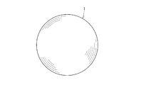
- FIG. 1 shows a bearing ball as an example of a sliding member and a rolling member.
- reference numeral 1 denotes a bearing ball.
- the bearing ball 1 is a true sphere.
- a bearing is configured by arranging a plurality of bearing balls.
- the entire surface of the bearing ball is a sliding surface.
- shape uniformity is also required.
- the area ratio of the grain boundary phase and the machinable coefficient Mc are adjusted to 0.100 to 0.120, so that the surface roughness (Ra) is 0.5 ⁇ m or less. Even if it is processed, there is little degranulation and the degranulation trace can be reduced. Therefore, when a polishing process using diamond abrasive grains is performed, a clean flat surface with few degranulation traces can be obtained.
- the sliding characteristics can be stabilized over a long period of time by controlling the area ratio of the grain boundary phase per unit area 100 ⁇ m ⁇ 100 ⁇ m, the crystal component, and the like.
- a durability of 700 hours or more, further 800 hours or more can be obtained.
- silicon nitride powder is prepared.
- the silicon nitride powder has an oxygen content of 1.7% by mass or less, contains ⁇ -phase type silicon nitride ( ⁇ -Si 3 N 4 ) of 85% by mass or more, has an average particle size of 1.0 ⁇ m or less, and further 0.8 ⁇ m.
- ⁇ -Si 3 N 4 ⁇ -phase type silicon nitride
- the following is preferable.
- a sintering aid powder is prepared.
- an Al component and a rare earth element component are essential components.
- at least 1 sort (s) chosen from a 4A group element component, a 5A group element component, and a 6A group element component and silicon carbide shall be added as needed.
- the total oxygen content of the sintering aid is preferably in the range of 1.20 to 2.50 parts by mass.
- the Al component is a sintering aid effective for reacting with ⁇ -Si 3 N 4 together with rare earth elements to form a hexagonal ⁇ -SiAlON crystal.
- the silicon nitride powder and the sintering aid powder are mixed.
- mixing is performed using a ball mill mixer or the like so as to obtain a uniform mixed state.
- hexagonal ⁇ -SiAlON crystals are easily formed uniformly.
- the index of dispersibility at this time is preferably managed using the following thixotropy index (TI value).
- TI value thixotropy index
- TI value ⁇ b / ⁇ a
- a binder is added to the raw material mixture obtained by mixing the silicon nitride powder and the sintering aid powder.
- the mixing of the raw material mixture and the binder is performed using a ball mill or the like while performing pulverization and granulation as necessary.
- the raw material mixture is formed into a desired shape.
- the molding process is performed by a die press, a cold isostatic press (CIP), or the like.
- the molding pressure is preferably 100 MPa or more.
- the molded body obtained in the molding process is degreased.
- the degreasing step is preferably performed at a temperature in the range of 300 to 600 ° C.
- the degreasing step is performed in the air or in a non-oxidizing atmosphere, and the atmosphere is not particularly limited.
- the degreased body obtained in the degreasing step is sintered at a temperature in the range of 1600 to 1900 ° C. If the sintering temperature is less than 1600 ° C., the crystal growth of silicon nitride crystal particles may be insufficient. That is, the reaction from ⁇ -Si 3 N 4 to ⁇ -Si 3 N 4 is insufficient, and a dense sintered body structure may not be obtained. In this case, the reliability as a material of the silicon nitride sintered body is lowered. If the sintering temperature exceeds 1900 ° C., the silicon nitride crystal grains grow too much, which may cause a decrease in strength and the ratio of the grain boundary phase may be out of the range.
- the above sintering step may be performed by either normal pressure sintering or pressure sintering.
- the sintering step is preferably performed in a non-oxidizing atmosphere.
- the non-oxidizing atmosphere include a nitrogen atmosphere and an argon atmosphere.
- HIP hot isostatic pressing
- non-oxidizing atmosphere examples include a nitrogen atmosphere and an argon atmosphere.
- the HIP treatment temperature is preferably in the range of 1500 to 1900 ° C.
- the silicon nitride sintered body thus manufactured is subjected to polishing processing at a necessary portion to produce a sliding member.
- the polishing process is preferably performed using diamond abrasive grains. Since the silicon nitride sintered body according to the embodiment has good workability, it is possible to reduce the processing cost when manufacturing the sliding member from the silicon nitride sintered body. Further, a flat surface having a surface roughness (Ra) of 0.5 ⁇ m or less, further 0.1 ⁇ m or less, and 0.05 ⁇ m or less can be obtained.
- Example 1 (Examples 1 to 13 and Comparative Examples 1 and 2)
- the silicon nitride powder one having an oxygen content of 1.2% by mass, an average particle diameter of 0.7 ⁇ m, and a ratio of ⁇ -Si 3 N 4 of 99% by mass was prepared.
- those shown in Table 1 were prepared as sintering aids.
- the sintering aid powder those having an average particle size of 1.3 ⁇ m or less were used.
- the silicon nitride powder and the sintering aid powder were blended and wet mixed for 50 hours by a ball mill. Mixing was performed so that the TI value at this time was 1.0 to 2.0. Next, after taking out from the solution and drying, it mixed with the binder and performed the mixing process for 20 hours with the ball mill, and mixed raw material powder was prepared, respectively.
- each raw material mixture was molded by a die press and degreased at 460 ° C.
- the degreased body was sintered in a nitrogen atmosphere at 1700 to 1800 ° C. for 4 to 6 hours.
- the obtained sintered body was subjected to HIP treatment.
- the HIP treatment was performed under the conditions of 1600 ° C. ⁇ 1 to 2 hours under a pressure of 100 MPa.
- silicon nitride sintered bodies according to Examples 1 to 13 and Comparative Examples 1 and 2 were produced.
- a sample for measuring three-point bending strength (silicon nitride sintered body) was used after being processed into a size of 3 mm ⁇ 4 mm ⁇ 50 mm.
- Example 1 to 13 and Comparative Examples 1 and 2 silicon nitride sintered bodies were polished to a surface roughness (Ra) of 0.1 ⁇ m or less. Thereafter, Vickers hardness (Hv), fracture toughness value (K 1C ), three-point bending strength, and machinable coefficient Mc were measured. Vickers hardness (Hv) was measured by a method according to JIS-R-1610 with an indentation load of 20 kgf. The fracture toughness value was measured according to the indenter press-fitting method (IF method) of JIS-R-1607 with an indentation load of 20 kgf and determined by the Niihara equation. The three-point bending strength was measured by a method according to JIS-R-1601. The results are shown in Table 2.
- the silicon nitride sintered body according to each example has a Vickers hardness (Hv) of 1500 or more and a fracture toughness value (K 1C ) of 6.0 MPa ⁇ m 1/2 or more, the three-point bending strength was 900 MPa or more, and the machinable coefficient Mc was in the range of 0.100 to 0.120.
- the area ratio of the grain boundary phase per unit area of 100 ⁇ m ⁇ 100 ⁇ m was determined using an SEM photograph of the polished surface of the cross section.
- the unit area of 100 ⁇ m ⁇ 100 ⁇ m was measured at five locations, and the upper limit and lower limit were described.
- the presence or absence of “Hf—Y—O-based compound crystal” and “Y—Al—O-based compound amorphous phase” in the grain boundary phase was examined by TEM analysis. The results are shown in Table 4 below.
- the silicon nitride sintered body according to each example had an area ratio of the grain boundary phase in the range of 25 to 40%.
- Example 1B to 13B and Comparative Examples 1B to 2B Using the same manufacturing method as in Examples 1 to 13 and Comparative Examples 1 and 2, bearing balls as sliding members were produced.
- the bearing ball was polished to have a diameter of 9.525 mm and a surface roughness (Ra) of 0.01 ⁇ m.
- the surface roughness (Ra) is prepared as a sample before polishing to 0.01 ⁇ m, and the surface roughness when the polishing process is performed using a diamond grindstone (# 120) is compared. did.
- the polishing conditions were as follows: the surface roughness after processing until the time when there was no change in the surface roughness (Ra), with the processing area of the sample being constant, the load being 40 N, the rotational speed of the grinding machine being 300 rpm, The thickness (Ra) was measured.
- the degranulation state can be measured by this polishing process.
- the degranulation state has a correlation with the surface roughness, meaning that the larger the value, the easier the degranulation occurs, and it is assumed that the reliability in the rolling life test tends to decrease.
- the rolling life and the change in crushing strength before and after the rolling life were measured.
- a bearing ball having a finished surface that was polished so that the surface roughness (Ra) was 0.01 ⁇ m was used.
- the rolling life three bearing balls according to each embodiment are prepared, and the three bearing balls are arranged at equal intervals on a track having a diameter of 40 mm set on the upper surface of the bearing steel SUJ2. This is the rolling life as the time until the surface of the bearing ball peels off at a rotational speed of 1200 rpm with a load applied so that the maximum contact stress of 5.9 GPa acts on the bearing ball under the oil bath lubrication condition of turbine oil. was measured. Note that the rolling life was measured with an upper limit of 800 hours continuous.
- the bearing balls according to the respective examples exhibited excellent sliding characteristics for 700 hours or more.
- Examples 1 to 6 having Hf—Y—O-based compound crystals and adding Mo 2 C as a sintering aid maintained excellent characteristics even after 800 hours.
- the bearing ball is a sliding member that uses the entire surface of the sintered body as a sliding surface. Therefore, if the characteristic as a bearing ball is excellent, even if it is used for other sliding members, the excellent characteristic is exhibited. Therefore, the silicon nitride sintered body of the embodiment can be applied to various sliding members.
- the silicon nitride sintered body and the sliding member using the same it is possible to provide a silicon nitride sintered body that can provide long-term reliability with respect to sliding characteristics.
- the machinable coefficient is adjusted, even if the surface is polished, it is easy to obtain a flat sliding surface because degranulation can be reduced. Therefore, long-term reliability can be obtained also with respect to the sliding member using the sintered body.
Landscapes
- Engineering & Computer Science (AREA)
- Chemical & Material Sciences (AREA)
- Ceramic Engineering (AREA)
- General Engineering & Computer Science (AREA)
- Manufacturing & Machinery (AREA)
- Materials Engineering (AREA)
- Structural Engineering (AREA)
- Organic Chemistry (AREA)
- Mechanical Engineering (AREA)
- Ceramic Products (AREA)
- Rolling Contact Bearings (AREA)
Abstract
窒化珪素焼結体をXRD分析した際に、六方晶系α-SiAlON結晶に対応する29.6±0.3°および31.0±0.3°に検出される最強ピーク強度をI29.6°、I31.0°とする一方、β-Si3N4結晶に対応する33.6±0.3°、36.1±0.3°に検出される最強ピーク強度をI33.6°、I36.1°としたときに、各最強ピーク強度が下記関係式:I29.6°+I31.0°)/(I33.6°+I36.1°)=0.10~0.30 …(1) を満たし、上記窒化珪素焼結体の任意の断面における単位面積100μm×100μm当りの粒界相の面積比が25~40%であり、マシナブル係数が0.100~0.120であることを特徴とする窒化珪素焼結体である。本発明によれば、摺動特性が長期間安定した摺動部材に好適な窒化珪素焼結体およびそれを用いた摺動部材を提供することができる。
Description
本発明の実施形態は窒化珪素焼結体およびそれを用いた摺動部材に関する。
窒化珪素焼結体は、ベアリングボール、ローラなどの摺動部材の構成材として広く用いられている。例えば、従来、回転軸を支持するベアリング(軸受)部材として、特にベアリングボールの構成材として、軸受鋼等の金属材料が一般に使用されていた。しかしながら、軸受鋼等の金属材料では耐摩耗性が十分ではないことから、軸受けの寿命のばらつきが大きくなり信頼性が高い高速回転駆動が安定して得られないという問題点があった。
上記のような問題点を解決する一手段として、近年になってベアリングボールの構成材として窒化珪素焼結体が用いられている。窒化珪素焼結体はセラミックスの中でも摺動特性に優れることから、一部の使用態様において耐摩耗性は十分であり、高速回転を行った場合においても信頼性が高い回転駆動をある程度の期間に亘って実現できることが確認されている。
従来の窒化珪素焼結体の焼結組成としては、窒化珪素-希土類酸化物-酸化アルミニウム系、窒化珪素-酸化イットリウム-酸化アルミニウム-窒化アルミニウム-チタニウム系等が知られている。上記焼結組成における酸化イットリウム(Y2O3)などの希土類酸化物等の焼結助剤は、従来から焼結助剤として一般に使用されており、焼結性を高めて焼結体を緻密化し高強度化するために添加されている。例えば、特開2006-36554号公報(特許文献1)に開示されている。
また、特開2002-326875号公報(特許文献2)には、所定の耐摩耗性試験を実施した場合に、400時間以上の長寿命を示す窒化珪素焼結体が開示されている。
一方、窒化珪素焼結体を使用したベアリングボールなどの摺動部材に対して、400時間以上、さらには800時間程度の長寿命が要求されるようになっている。ベアリングボールの長寿命化を行うことにより、軸受けなどの摺動部のメンテナンスフリー化を実現することができる。
軸受けなどの摺動部材は工作機器、電子機器、自動車、航空機さらには風力発電など様々な分野の製品に使用されている。摺動部材の長寿命化が実現すると、各種製品の長寿命化、さらにはメンテナンスフリー化を達成することができる。
本発明が解決しようとする課題は、摺動特性の更なる長期信頼性を具備させることが可能な窒化珪素焼結体およびそれを用いた摺動部材を提供することである。
本発明の一実施形態によれば、窒化珪素焼結体をXRD分析した際に、六方晶系α-SiAlON結晶に対応する29.6±0.3°および31.0±0.3°に検出される最強ピーク強度をI29.6°、I31.0°とする一方、β-Si3N4結晶に対応する33.6±0.3°、36.1±0.3°に検出される最強ピーク強度をI33.6°、I36.1°としたときに、各最強ピーク強度が下記関係式:
(I29.6°+I31.0°)/(I33.6°+I36.1°)=0.10~0.30 …(1)
を満たし、上記窒化珪素焼結体の任意の断面における単位面積100μm×100μm当りの粒界相の面積比が25~40%であり、マシナブル係数が0.100~0.120であることを特徴とする窒化珪素焼結体が得られる。
(I29.6°+I31.0°)/(I33.6°+I36.1°)=0.10~0.30 …(1)
を満たし、上記窒化珪素焼結体の任意の断面における単位面積100μm×100μm当りの粒界相の面積比が25~40%であり、マシナブル係数が0.100~0.120であることを特徴とする窒化珪素焼結体が得られる。
また、窒化珪素焼結体をXRD分析した際に、Y4Si2O7N2(J相)に対応する39.5±0.3°に検出される最強ピーク強度I39.5°が、下記関係式:
(I39.5°)/(I33.6°+I36.1°)=0.03~0.10 …(2)
を満たすことが好ましい。また、窒化珪素焼結体をXRD分析した際に、Y2Si3O12N(H相)、YSiO2N(K相)またはY2Si3O3N4のいずれか1種以上に対応する31.9±0.3°に検出される最強ピーク強度I31.9°が、下記関係式:
(I31.9°)/(I33.6°+I36.1°)=0.05~0.15 …(3)
を満たすことが好ましい。また、XRD分析は窒化珪素焼結体の任意の断面で行うことが好ましい。
(I39.5°)/(I33.6°+I36.1°)=0.03~0.10 …(2)
を満たすことが好ましい。また、窒化珪素焼結体をXRD分析した際に、Y2Si3O12N(H相)、YSiO2N(K相)またはY2Si3O3N4のいずれか1種以上に対応する31.9±0.3°に検出される最強ピーク強度I31.9°が、下記関係式:
(I31.9°)/(I33.6°+I36.1°)=0.05~0.15 …(3)
を満たすことが好ましい。また、XRD分析は窒化珪素焼結体の任意の断面で行うことが好ましい。
また、Hf-Y-O系化合物結晶とY-Al-Oとを含有する非晶質相を含む粒界相を具備することが好ましい。また、平均粒径2μm以下の炭化物、酸化物、窒化物等の粒子を具備することが好ましい。また、前記粒子がモリブデン化合物の粒子であることが好ましい。また、Alを酸化物換算値で5~10質量%、希土類元素のいずれか1種類以上を酸化物換算値で1~10質量%、4A、5A、6A元素のいずれか1種類以上を酸化物換算値で1~5質量%含有し、かつ、Alと希土類元素とのmol比が、Al(mol):希土類元素(mol)=1:1~8:1であることが好ましい。また、ビッカース硬度(Hv)が1500以上であり、破壊靭性値(K1C)が6.0MPa・m1/2以上であり、かつ、3点曲げ強度が900MPa以上であることが好ましい。
また、実施形態に係る摺動部材は、前記実施形態の窒化珪素焼結体を用いたことを特徴とするものである。また、摺動部材がベアリングボールであることが好ましい。また、摺動面は表面粗さ(Ra)が0.5μm以下の研磨面であることが好ましい。
本実施形態は、摺動特性に関して長期信頼性を付与できる窒化珪素焼結体を提供できる。また、マシナブル係数を調整してあるので表面研磨加工したとしても、脱粒を小さくできるので平坦な摺動面を得易い。そのため、その焼結体を使用した摺動部材に関しても長期信頼性を得ることができる。
以下、実施の形態について説明する。
(第一の実施形態)
第一の実施形態は、窒化珪素焼結体をXRD分析した際に、六方晶系α-SiAlON結晶に対応する29.6±0.3°および31.0±0.3°に検出される最強ピーク強度をI29.6°、I31.0°とする一方、β-Si3N4結晶に対応する33.6±0.3°、36.1±0.3°に検出される最強ピーク強度をI33.6°、I36.1°としたときに、各最強ピーク強度が関係式:
(I29.6°+I31.0°)/(I33.6°+I36.1°)=0.10~0.30 …(1)
を満たし、上記窒化珪素焼結体の任意の断面における単位面積100μm×100μm当りの粒界相の面積比が25~40%であり、マシナブル係数が0.100~0.120であることを特徴とする窒化珪素焼結体である。
第一の実施形態は、窒化珪素焼結体をXRD分析した際に、六方晶系α-SiAlON結晶に対応する29.6±0.3°および31.0±0.3°に検出される最強ピーク強度をI29.6°、I31.0°とする一方、β-Si3N4結晶に対応する33.6±0.3°、36.1±0.3°に検出される最強ピーク強度をI33.6°、I36.1°としたときに、各最強ピーク強度が関係式:
(I29.6°+I31.0°)/(I33.6°+I36.1°)=0.10~0.30 …(1)
を満たし、上記窒化珪素焼結体の任意の断面における単位面積100μm×100μm当りの粒界相の面積比が25~40%であり、マシナブル係数が0.100~0.120であることを特徴とする窒化珪素焼結体である。
まず、XRD分析を実施する条件について説明する。測定面は焼結体の任意の表面または任意の断面であり、表面粗さRaが1μm以下に研磨された研磨面とする。XRD分析は、Cuターゲット(Cu-Kα)、管電圧40kV、管電流40mA、スキャンスピート2.0°/min、スリット(RS)0.15mm、走査範囲(2θ)10°~60°にて行うものとする。なお、走査範囲(2θ)は、10°~60°を含んでいれば広い範囲を行ってもよいものとする。特に、焼結体の断面であることが好ましい。断面にて分析すれば、粒界相の面積比を求める面としても使用することができる。
第一の実施形態ではXRD分析したとき、六方晶系α-SiAlON結晶に対応する29.6±0.3°および31.0±0.3°に検出される最強ピーク強度をI29.6°、I31.0°とする一方、β-Si3N4結晶に対応する33.6±0.3°、36.1±0.3°に検出される最強ピーク強度をI33.6°、I36.1°としたときに各最強ピーク強度が下記関係式:(I29.6°+I31.0°)/(I33.6°+I36.1°)=0.10~0.30を満たすものとする。XRD分析によるピーク位置は、それぞれの結晶の格子定数によって決定される。
六方晶系α-SiAlON結晶が存在すれば、29.6±0.3°および31.0±0.3°にピークが検出される。言い換えると、29.6±0.3°および31.0±0.3°にピークが検出されると六方晶系α-SiAlON結晶が存在することを意味する。また、I29.6°およびI31.0°の両方のピーク強度を用いる理由は、結晶の配向性によるピーク強度の変化の影響を緩和するためである。
また、β-Si3N4結晶が存在すれば、33.6±0.3°および36.1±0.3°にピークが検出される。言い換えると、33.6±0.3°および36.1±0.3°にピークが検出されるとβ-Si3N4結晶が存在することを意味する。また、I33.6°およびI36.1°の両方のピーク強度を用いる理由は、結晶の配向性によるピーク強度の変化の影響を緩和するためである。
第一の実施形態では、(I29.6°+I31.0°)/(I33.6°+I36.1°)=0.10~0.30を満たすものである。ピーク強度の大きさは、それぞれの結晶の存在量に応じて決まる。(六方晶α-SiAlON結晶/β-Si3N4結晶)ピーク強度比である(I29.6°+I31.0°)/(I33.6°+I36.1°)が0.10~0.30であるということは、β-Si3N4結晶に対し六方晶系α-SiAlON結晶が所定量存在することを意味する。
また、六方晶α-SiAlON結晶が存在すれば、34.4°、35.1°付近にもピークが検出される。また、β-Si3N4結晶が存在すれば、23.4°、27.1°付近にもピークが検出される。この辺のピークの検出の有無も六方晶α-SiAlON結晶およびβ-Si3N4結晶の存在の有無を把握するのに使用してもよい。また、後述する他の結晶のピークと重なって判別しにくい時は、各種定性分析と組み合わせてもよい。
六方晶系α-SiAlON結晶を存在させることにより、六方晶系α-SiAlON結晶とβ-Si3N4結晶とが混在した組織となり、粒界相の存在バラツキを低減することができ、粒界相を強化することができる。そのため、焼結体としての硬度、靭性などが向上し、耐摩耗性も向上させることができる。六方晶系α-SiAlON結晶は、球状形状または柱状形状の両方があってもよい。
特に、六方晶α-SiAlON結晶はアスペクト比が2以下であることが好ましい。β-Si3N4結晶は、アスペクト比が2以上の長柱状形状である。特許文献1や特許文献2の窒化珪素焼結体は、β-Si3N4結晶が複雑に絡み合って硬度や靭性の高い窒化珪素焼結体を形成している。一方でβ-Si3N4結晶は長柱状形状であることから、β-Si3N4結晶同士の粒界サイズのバラツキが大きく、部分的に粒界相の多い箇所と少ない箇所が形成されていた。このため、摺動特性の長期寿命の低下がみられた。
第一の実施形態では、長柱状形状のβ-Si3N4結晶と、球状または柱状の六方晶α-SiAlON結晶が混在していることから、β-Si3N4結晶同士の隙間に六方晶α-SiAlON結晶が入り込む構造となり、粒界相の存在割合を安定させることができる。
(六方晶α-SiAlON結晶/β-Si3N4結晶)のピーク強度比が0.10未満では、六方晶α-SiAlON結晶が少な過ぎて粒界相の存在割合のバラツキが大きくなる。一方、(六方晶α-SiAlON結晶/β-Si3N4結晶)のピーク強度比が0.30を超えて大きいと、β-Si3N4結晶の割合が低下し、β-Si3N4結晶が複雑に絡み合った組織が減って摺動特性が低下する。
また、窒化珪素焼結体の任意の断面における単位面積100μm×100μm当りの粒界相の面積比を25~40%とすることにより、粒界相の存在バラツキを制御し易くなる。第一の実施形態において、β-Si3N4結晶と六方晶α-SiAlON結晶以外を粒界相とするものとする。第一の実施形態の窒化珪素焼結体は、任意の断面、つまりはどこの断面を測定したとしても単位面積100μm×100μm当りの粒界相の面積比が25~40%の範囲内となる。単位面積100μm×100μmという微小領域にて粒界相の割合を制御しているので焼結体の硬度や破壊靭性の向上のみならず、摺動特性の長期信頼性を得ることができる。
なお粒界相の面積比の測定方法は次の通りである。まず、窒化珪素焼結体の任意の断面を得る。この断面を表面粗さRaが1μm以下となるように研磨加工を施す。β-Si3N4結晶および六方晶α-SiAlON結晶と粒界相の領域を明確にするために、得られた研磨面にプラズマエッチング処理を行う。
プラズマエッチング処理を実施すると、β-Si3N4結晶および六方晶α-SiAlON結晶と粒界相のエッチングレートが異なるため、どちらか一方が多く削除される。例えばCF4を用いたプラズマエッチングでは、β-Si3N4結晶および六方晶α-SiAlON結晶の方が、エッチングレートが高い(エッチングされ易い)ので、β-Si3N4結晶および六方晶α-SiAlON結晶が凹部、粒界相が凸部となる。
なお、エッチング処理は酸およびアルカリを用いるケミカルエッチングでも可能である。エッチング処理後の鏡面をSEM画像撮影(1000倍以上の倍率)する。SEM写真では、β-Si3N4結晶および六方晶α-SiAlON結晶と粒界相がコントラストの差で区別できる。通常は、粒界相が白色に見える。エッチング処理を行うことにより、コントラストの差をより明瞭にすることができる。
SEM写真を画像解析することにより、単位面積当たりの粒界相の面積比を測定できる。なお、画像解析は、粒界相部分をカラーマッピングして画像解析する方法が有効である。また、一視野で単位面積100μm×100μmにならない場合は、複数回撮影し、合計で単位面積100μm×100μmにしてもよいものとする。
また、第一の実施形態の窒化珪素焼結体は、マシナブル係数が0.100~0.120である。
上記マシナブル係数Mcは下記の式(4)から算出される値である。
Mc=Fn9/8/(K1c
1/2・Hv5/8) …(4)
式(4)において、Fnは押込み荷重であり、ここでは20kgfとする。20kgfの押込み荷重Fnは、窒化珪素焼結体の硬度や靭性を測定する上で好適な値である。ビッカース硬度(Hv)は、JIS-R-1610に準じて測定するものとする。破壊靭性値(K1C)は、JIS-R-1607の圧子圧入法(IF法)に準じて測定するものとする。破壊靭性値の計算には、新原の式を用いるものとする。後述するベアリングボールについては、その断面を使用して測定するものとする。
式(4)において、Fnは押込み荷重であり、ここでは20kgfとする。20kgfの押込み荷重Fnは、窒化珪素焼結体の硬度や靭性を測定する上で好適な値である。ビッカース硬度(Hv)は、JIS-R-1610に準じて測定するものとする。破壊靭性値(K1C)は、JIS-R-1607の圧子圧入法(IF法)に準じて測定するものとする。破壊靭性値の計算には、新原の式を用いるものとする。後述するベアリングボールについては、その断面を使用して測定するものとする。
マシナブル係数Mcは、押込み荷重(Fn)、ビッカース硬度(Hv)および破壊靭性値(K1C)を使用した加工性を示す係数である。これはラテラル亀裂破壊モデルの関係式であり、Mcは1粒の砥粒により取り除かれる物質量を示している。マシナブル係数Mcが大きいほど一度に加工できる量が大きくなることを意味している。
ラテラル亀裂破壊モデルとは、研削加工時の材料の除去メカニズムとして、Evans氏とMarshall氏によって提案されたモデルである。このモデルにおいて、1つの研削砥粒が材料表面を通過するときに取り除かれる物質の量(デルタV)は、砥粒を材料に垂直方向に押し込む力Fnとビッカース硬さ(Hv)と破壊靭性値(K1C)との関係において、[Fn9/8/(K1c
1/2・Hv5/8)]の値に比例すると示されている。ここでは、デルタVをマシナブル係数Mcと置き換えている。
加工は大別して、脆性モードと延性モードとに分けられる。脆性モードはいわゆる粗加工に相当し、延性モードはいわゆる仕上げ加工に相当する。摩耗とは延性モードに相当すると考えられるので、耐摩耗性部材の要求性能を満足させるためには、延性モードの加工性を低下させることなく、脆性モードの加工性を改善することが重要となる。また、摩耗モデルの1つとしては、粒界に微小な予亀裂が発生し、その伝播により材料表面の破壊に至り、摩耗が発生する機構が考えられている。
摩耗モデルの機械的接触の過酷さを表すパラメータSc.mは、摩擦係数μ、最大ヘルツ応力Pmax、材料の結晶粒径d、破壊靭性値K1cから下式で表される。
Sc.m=[(1+10・μ)・Pmax・(d1/2)]/K1c
パラメータSc.mが大きいと摩耗が大きく、パラメータSc.mが小さいと摩耗が小さいことを意味する。材料の結晶粒径dを小さくすることや破壊靭性値K1cを大きくすることで、摩耗を抑えることが可能であることが分かる。
パラメータSc.mが大きいと摩耗が大きく、パラメータSc.mが小さいと摩耗が小さいことを意味する。材料の結晶粒径dを小さくすることや破壊靭性値K1cを大きくすることで、摩耗を抑えることが可能であることが分かる。
これらの点を考慮した場合、マシナブル係数Mcは0.100~0.120の範囲が好ましい。マシナブル係数Mcが0.100未満の場合には、砥粒による研磨加工量が少ないため、窒化珪素焼結体の研磨加工時間が増大する。マシナブル係数Mcが0.120を超えると、砥粒による窒化珪素焼結体の研磨加工量が大きくなりすぎる。研磨加工量が大きいと加工性は向上するものの、摺動部材としての耐久性が低下する。
マシナブル係数Mcが0.100~0.120の範囲である窒化珪素焼結体は、焼結体として硬度および破壊靭性を向上させた上で、摺動特性を向上させることができる。また、摺動面を研磨加工する際の脱粒痕を小さくすることができるので表面粗さRaが0.5μm以下、さらには0.1μm以下の平坦面が得易い。加工性を考慮するとマシナブル係数Mcは0.110~0.120の範囲であることが好ましい。
また、窒化珪素焼結体をXRD分析した際に、Y4Si2O7N2(J相)に対応する39.5±0.3°に検出される最強ピーク強度I39.5°は、関係式:(I39.5°)/(I33.6°+I36.1°)=0.03~0.10を満たすことが好ましい。
Y4Si2O7N2(J相)は粒界相に存在する結晶相である。39.5±0.3°にピークが検出されるということは、Y4Si2O7N2(J相)が存在するということを意味するものである。Y4Si2O7N2(J相)のピーク強度比(I39.5°)/(I33.6°+I36.1°)を0.03~0.10の範囲とすることにより、粒界相を強化することができる。粒界相を強化することにより摺動特性の長期信頼性をさらに向上させることができる。
なお、Y4Si2O7N2(J相)が存在すれば、31.0°、34.4°、36.1°、39.5°、44.5°付近(±0.3°)にもピークが検出される。I39.5°を選択したのは、J相に応じたピークの中で最強ピークを示す可能性が高いためである。
また、窒化珪素焼結体をXRD分析した際に、Y2Si3O12N(H相)、YSiO2N(K相)またはY2Si3O3N4のいずれか1種以上に対応する31.9±0.3°に検出される最強ピーク強度I31.9°は、(I31.9°)/(I33.6°+I36.1°)=0.05~0.15を満たすことが好ましい。
Y2Si3O12N(H相)、YSiO2N(K相)またはY2Si3O3N4のいずれか1種は、粒界相に存在する結晶相である。31.9±0.3°にピークが検出されるということは、Y2Si3O12N(H相)、YSiO2N(K相)またはY2Si3O3N4のいずれか1種以上の結晶相が存在することを意味するものである。
ピーク強度比(I31.9°)/(I33.6°+I36.1°)を0.05~0.15の範囲とすることにより、粒界相を強化することができる。粒界相を強化することにより摺動特性の長期信頼性をさらに向上させることができる。また、I31.9°を選択した理由はY2Si3O12N(H相)、YSiO2N(K相)またはY2Si3O3N4のいずれか1種以上に応じたピークの中の最強ピークの1つであることに起因している。
また、Hf-Y-O系化合物結晶とY-Al-Oとを含有する非晶質相を含む粒界相を具備することが好ましい。Hf-Y-O系化合物結晶は、ハフニウムとイットリウムと酸素とを含む化合物結晶である。また、Y-Al-Oを含有する非晶質相は、少なくともイットリウムとアルミニウムと酸素とを含む非晶質相である。
ハフニウムは、活性な成分であり、イットリウムや酸素と反応してHf-Y-O系化合物結晶を形成し、Si3N4の成長反応を促進する。このとき、Y4Si2O7N2(J相)、Y2Si3O12N(H相)、YSiO2N(K相)またはY2Si3O3N4の1種以上の形成にも寄与すると考えられる。
また、Y-Al-Oを含有する相を非晶質相(ガラス相)とすることにより、粒界相の均質な分布を制御しやすくなる。なお、Hf-Y-O系化合物結晶とY-Al-Oとを含有する非晶質相の存在の有無はTEM分析により確認できる。
また、平均粒径2μm以下の炭化物、酸化物、窒化物等の粒子を具備することが好ましい。上記粒子としては、珪素(Si)、5A族であるバナジウム(V)、ニオブ(Nb)、タンタル(Ta)、6A族であるクロム(Cr)、モリブデン(Mo)、タングステン(W)、から選ばれる少なくとも1種以上の粒子であることが好ましい。
上記粒子は、粒界相に存在することにより、粒界相の強化に資する。また、粒界相の強化を実現するためには平均粒径2μm以下、さらには1.5μm以下であることが好ましい。平均粒径が2μmを超えて大きいと、粒界の連続分布性を阻害し、構造欠陥の起因となるおそれがある。
また、上記粒子がモリブデン化合物粒子であることが好ましい。モリブデン化合物粒子は潤滑性があることから、摺動面(窒化珪素焼結体の表面)に存在することにより、摺動面の摺動特性を向上させることができる。また、モリブデン化合物粒子は炭化モリブデン(Mo2C)粒子が潤滑性に優れている。
また、β-Si3N4結晶は、長径が2μm以上であり、最大アスペクト比が7以下であることが好ましい。また、六方晶α-SiAlON結晶は球状形状、柱状形状のいずれも平均粒径が2μm以下であることが好ましい。なお球状形状、柱状形状(アスペクト比2以下)の平均粒径は長軸を使った等価円の直径を粒径とし、100粒の平均値により求めるものとする。
また、Alを酸化物換算値で5~10質量(wt)%、希土類元素のいずれか1種類以上を酸化物換算値で1~10質量%、4A、5A、6A元素のいずれか1種類以上を酸化物換算値で1~5質量%含有し、かつ、Alと希土類元素とのmol比が、Al(mol):希土類元素(mol)=1:1~8:1であることが好ましい。
Al(アルミニウム)は、焼結性を向上させる成分であると共に、六方晶α-SiAlON結晶やY-Al-O系化合物非晶質相を形成するのに必要な成分である。また、焼結助剤として添加する場合は、Al2O3(酸化アルミニウム)、AlN(窒化アルミニウム)であることが好ましい。Alが酸化物換算で5質量%未満であると、粒界相の割合が低下するおそれがあると共に、各種の結晶成分や非晶質成分の形成が不足するおそれがある。一方、10質量%を超えると粒界相が多くなり過ぎるおそれがある。
希土類元素は、Y(イットリウム)、La(ランタン)、Ce(セリウム)、Pr(プラセオジム)、Nd(ネオジウム)、Pm(プロメチウム)、Sm(サマリウム)、Eu(ユーロピウム)、Gd(ガドリウム)、Tb(テルビウム)、Dy(ジスプロシウム)、Ho(ホルミウム)、Er(エルビウム)、Tm(ツリウム)、Yb(イッテルビウム)、Lu(ルテチウム)の少なくとも1種以上であることが好ましい。また、焼結助剤として添加する場合は、希土類酸化物として添加することが好ましい。また、希土類元素のいずれか1種類以上を酸化物換算値で1質量%未満、10質量%を超えると粒界相の割合が実施形態の範囲外となるおそれがあり、また、Al元素とのモル比の調整が困難になる。
また、希土類元素の中ではイットリウムが好ましい。イットリウムであれば、Y4Si2O7N2(J相)、Y2Si3O12N(H相)、YSiO2N(K相)、Y2Si3O3N4、Hf-Y-O系化合物結晶、Y-Al-Oを含有する非晶質相を形成する成分として機能する。また、α-SiAlON結晶の生成も促進する。
また、4A、5A、6A元素のいずれか1種類以上を酸化物換算値で1~5質量%含むことが好ましい。4A族元素は、Ti(チタン)、Zr(ジルコニウム)、Hf(ハフニウム)である。また、5A族元素は、V(バナジウム)、Nb(ニオブ)、Ta(タンタル)である。また、6A族元素は、Cr(クロム)、Mo(モリブデン)、W(タングステン)である。4A族元素の酸化物換算は、TiO2、ZrO2、HfO2にて換算するものとする。また、5A族元素の酸化物換算は、V2O5,Nb2O5,Ta2O5にて換算するものとする。また、6A族元素の酸化物換算は、Cr2O3、MoO3、WO3にて換算するものとする。
また、焼結助剤として添加する場合は、酸化物、炭化物、窒化物のいずれか1種以上で添加することが好ましい。また、4A族元素は酸化物、5A族元素および6A族元素は炭化物として添加することが好ましい。また、4A族元素はHf、6A族元素はMoであることが好ましい。Hfは前述のようにHf-Y-O系化合物結晶を形成する成分として機能する。また、Moを炭化モリブデン(Mo2C)粒子として添加することが好ましい。前述のようにモリブデン化合物粒子は粒界相強化成分になると共に、摺動面の潤滑性を向上させる成分として機能する。5A族元素および6A族元素の粒子は潤滑性を有しているが、その中でもモリブデン化合物が最も優れた潤滑性を有する。
また、前記以外の成分としては、炭化物粒子として炭化珪素(SiC)が挙げられる。炭化珪素を添加する場合は1~5wt%の範囲内であることが好ましい。
また、Alと希土類元素のmol比がAl(mol):希土類元素(mol)=1:1~8:1であることが好ましい。Al量を希土類元素量の1~8倍存在させることにより、六方晶α-SiAlON結晶が形成され易くなる。また、Al(mol):希土類元素(mol)=1.4:1~7.0:1の範囲内であることが好ましい。
また、前述の各成分を焼結助剤として添加する場合、窒化珪素粉末量を100質量部としたとき、焼結助剤の合計の酸素量が1.20~2.50質量部の範囲となることが好ましい。各種焼結助剤の添加形態として窒化物または炭化物として添加する割合を調製することにより、酸化物として添加する量を上記範囲とすることができる。例えば、Al成分をAlN、Mo成分をMo2Cなどで添加する方法が挙げられる。燒結助剤の合計の酸素量を低減して、窒化物を増やすことによっても、六方晶α-SiAlON結晶を形成し易くなる。また、酸化物焼結助剤はY-Al-Oを含有する非晶質相などの粒界相の形成に寄与する。そのため、焼結助剤の合計酸素量を前記範囲にすることによっても、粒界相の面積比を制御することができる。
また、上記のような窒化珪素焼結体であれば、ビッカース硬度(Hv)が1500以上、破壊靭性値(K1c)が6.0MPa・m1/2以上、3点曲げ強度が900MPa以上と優れた特性を示すことができる。
なお、ビッカース硬度(Hv)は、JIS-R-1610に準じて測定するものとする。破壊靭性値(K1C)は、JIS-R-1607の圧子圧入法(IF法)に準じて測定するものとする。また、破壊靭性値の計算には、新原の式を用いるものとする。また、3点曲げ強度はJIS-R-1601に準じて測定する。
(第二の実施形体)
第二の実施形態は、第一の実施形態の窒化珪素焼結体を用いた摺動部材である。摺動部材としては、ベアリングボール、ローラ、チェックボール、ウエアパッド、プランジャー、コロなどが挙げられる。これら摺動部材は、金属部材やセラミックスなどからなる相手部材と摺動する。摺動面の耐久性を上げるためには、表面粗さ(Ra)が0.5μm以下、さらには0.1μm以下、より好ましくは0.05μm以下に研磨加工した研磨面とすることが好ましい。摺動面を平坦にすることにより、窒化珪素焼結体の耐久性を向上させると共に相手部材への攻撃性を低下させることができる。相手部材への攻撃性を低下させることにより、相手部材の消耗を低減できるので摺動部材を組み込んだ装置の耐久性を向上させることができる。
第二の実施形態は、第一の実施形態の窒化珪素焼結体を用いた摺動部材である。摺動部材としては、ベアリングボール、ローラ、チェックボール、ウエアパッド、プランジャー、コロなどが挙げられる。これら摺動部材は、金属部材やセラミックスなどからなる相手部材と摺動する。摺動面の耐久性を上げるためには、表面粗さ(Ra)が0.5μm以下、さらには0.1μm以下、より好ましくは0.05μm以下に研磨加工した研磨面とすることが好ましい。摺動面を平坦にすることにより、窒化珪素焼結体の耐久性を向上させると共に相手部材への攻撃性を低下させることができる。相手部材への攻撃性を低下させることにより、相手部材の消耗を低減できるので摺動部材を組み込んだ装置の耐久性を向上させることができる。
摺動部材を組み込んだ装置としては、工作機器、電子機器、自動車、航空機さらには風力発電など様々な分野の製品が挙げられる。
図1に、摺動部材および転動部材の一例としてベアリングボールを示した。図1中、符号1はベアリングボールである。ベアリングボール1は、真球状の球体である。一般的に、複数個のベアリングボールを配置して軸受けが構成される。ベアリングボールは表面全体が摺動面となる。また、軸受けを構成するにあたり、複数個のベアリングボールを用いることから、形状の均一性も求められる。第一の実施形態の窒化珪素焼結体は、粒界相の面積比およびマシナブル係数Mcを0.100~0.120に調整してあるので、表面粗さ(Ra)0.5μm以下の研磨加工を施したとしても脱粒が少なく、脱粒痕も小さくできる。そのため、ダイヤモンド砥粒を使った研磨加工を行った場合に、脱粒痕の少ない、きれいな平坦面が得られる。
また、単位面積100μm×100μmあたりの粒界相の面積比や、結晶成分などの制御により、摺動特性を長期に渡り安定化させることができる。例えば、従来、ベアリングボールの場合、連続運転にて400~500時間の耐久性であったものが、700時間以上、さらには800時間以上の耐久性を得ることができる。そのため、摺動部材の長期信頼性を維持するだけでなく、それを組み込んだ装置の長期信頼性またはメンテナンスフリー化などの効果も得られる。
(第一の実施形態の窒化珪素焼結体の製造方法)
次に製造方法について説明する。第一の実施形態の窒化珪素焼結体は上記構成を有すれば特に製造方法は限定されるものではないが効率的に得るための方法として次のものが挙げられる。
次に製造方法について説明する。第一の実施形態の窒化珪素焼結体は上記構成を有すれば特に製造方法は限定されるものではないが効率的に得るための方法として次のものが挙げられる。
まず、窒化珪素粉末を用意する。窒化珪素粉末は酸素含有量が1.7質量%以下で、α相型窒化珪素(α-Si3N4)を85質量%以上含み、平均粒子径が1.0μm以下、さらには0.8μm以下であることが好ましい。α-Si3N4粉末を焼結工程でβ-Si3N4結晶に粒成長させることにより、摺動特性の優れた窒化珪素焼結体を得ることができる。
次に、焼結助剤粉末を用意する。焼結助剤としては、Al成分および希土類元素成分を必須成分とする。また、必要に応じて、4A族元素成分、5A族元素成分および6A族元素成分から選ばれる少なくとも1種以上、および炭化珪素を添加するものとする。
また、前述のように、Alと希土類元素のmol比がAl(mol):希土類元素(mol)=1:1~8:1となるように添加することが好ましい。また、焼結助剤を添加する際、窒化珪素粉末量を100質量部としたとき、焼結助剤の合計の酸素量が1.20~2.50質量部の範囲となることが好ましい。焼結助剤として添加する成分の酸素量を制御するために、Al成分をAlN、5A族元素成分および6A族元素成分を炭化物として添加することが好ましい。特に、AlNは希土類元素と共にα-Si3N4と反応して六方晶α-SiAlON結晶を形成するのに有効な焼結助剤となる。
次に上記窒化珪素粉末と焼結助剤粉末とを混合する。混合工程は、ボールミル混合機などを使用して均一混合状態となるように混合する。特に、α-Si3N4粉末とAlN粉末および希土類化合物の分散状態が均一混合とすることにより、六方晶α-SiAlON結晶が均一に形成され易くなる。また、均一混合のためには、ボールミル混合機などを使った混合工程を50時間以上実施することが好ましい。また、混合工程を溶液中で行う湿式混合法とすることも均一混合には有効である。
また、湿式にて原料混合物を調製する工程において、Al系化合物および希土類化合物を予め分散性の良いスラリーに調製してから、主原料である窒化珪素粉末のスラリーに混合することが好ましい。この時の分散性の指標は、下記チクソトロピーインデックス(TI値)を用いて管理するのが好ましい。回転粘度計において連続的にせん断速度a、bを上げていくと、凝集性を持つ流体では粘度が低下するのが一般的である。この時、せん断速度aとbにおける粘度値ηの比がTI値となる。
TI値=ηb/ηa
せん断速度a,bの値には特に決まりはないが、TI値が1以上の値をとるように設定するのがよい。TI値が1に近づくほど、ニュートン流体の挙動に近くなり、凝集のない、あるいは凝集の極めて弱い高分散のスラリーであることを示唆する。本件ではa=6(1/s)、b=60(1/s)としたときのTI値が1.0~2.0の値をとるように調整した。なお、sは秒を示す。このような混合方式を用いることにより、焼結時の六方晶α-SiAlON結晶の均一な粒成長を効果的に行うことが可能となる。
せん断速度a,bの値には特に決まりはないが、TI値が1以上の値をとるように設定するのがよい。TI値が1に近づくほど、ニュートン流体の挙動に近くなり、凝集のない、あるいは凝集の極めて弱い高分散のスラリーであることを示唆する。本件ではa=6(1/s)、b=60(1/s)としたときのTI値が1.0~2.0の値をとるように調整した。なお、sは秒を示す。このような混合方式を用いることにより、焼結時の六方晶α-SiAlON結晶の均一な粒成長を効果的に行うことが可能となる。
次に、窒化珪素粉末と焼結助剤粉末とを混合した原料混合物にバインダを添加する。原料混合物とバインダとの混合はボールミル等を使用し、必要に応じて粉砕や造粒を行いながら実施する。原料混合物を所望の形状に成形する。成形工程は、金型プレスや冷間静水圧プレス(CIP)等により実施する。成形圧力は100MPa以上が好ましい。次に、成形工程で得た成形体を脱脂する。脱脂工程は300~600℃の範囲の温度で実施することが好ましい。脱脂工程は大気中や非酸化性雰囲気中で実施され、雰囲気は特に限定されるものではない。
次に、脱脂工程で得た脱脂体を1600~1900℃の範囲の温度で焼結する。焼結温度が1600℃未満であると、窒化珪素結晶粒子の粒成長が不十分になるおそれがある。すなわち、α-Si3N4からβ-Si3N4への反応が不十分であり、緻密な焼結体組織が得られないおそれがある。この場合、窒化珪素焼結体の材料としての信頼性が低下する。焼結温度が1900℃を超えると窒化珪素結晶粒子が粒成長し過ぎて、強度低下を引き起こすおそれや粒界相の割合が範囲外となるおそれがある。
上記焼結工程は、常圧焼結および加圧焼結のいずれで実施してもよい。焼結工程は非酸化性雰囲気中で実施することが好ましい。非酸化性雰囲気としては、窒素雰囲気やアルゴン雰囲気が挙げられる。
焼結工程の後に、非酸化性雰囲気中にて30MPa以上の熱間静水圧プレス(HIP)処理を施すことが好ましい。非酸化性雰囲気としては、窒素雰囲気やアルゴン雰囲気が挙げられる。HIP処理温度は1500~1900℃の範囲であることが好ましい。HIP処理を実施することによって、窒化珪素焼結体内の気孔を消滅させることができる。HIP処理圧力が30MPa未満であると、そのような効果を十分に得ることができない。
このようにして製造された窒化珪素焼結体に対して、必要な箇所に研磨加工を施して摺動部材を作製する。研磨加工は、ダイヤモンド砥粒を用いて実施することが好ましい。実施形態の窒化珪素焼結体は良好な加工性を有しているため、窒化珪素焼結体から摺動部材を作製する際の加工コストを低減することができる。また、表面粗さ(Ra)が0.5μm以下、さらには0.1μm以下、0.05μm以下の平坦面を得ることができる。
(実施例1)
(実施例1~13および比較例1~2)
窒化珪素粉末として、酸素含有量が1.2質量%であり、平均粒径が0.7μmであり、α-Si3N4の割合が99質量%のものを用意した。次に、焼結助剤として表1に示すものを用意した。なお、焼結助剤粉末は、いずれも平均粒径1.3μm以下のものを使用した。

(実施例1~13および比較例1~2)
窒化珪素粉末として、酸素含有量が1.2質量%であり、平均粒径が0.7μmであり、α-Si3N4の割合が99質量%のものを用意した。次に、焼結助剤として表1に示すものを用意した。なお、焼結助剤粉末は、いずれも平均粒径1.3μm以下のものを使用した。
次に上記窒化珪素粉末および焼結助剤粉末を配合し、ボールミルにより50時間の湿式混合を行った。このときのTI値が1.0~2.0なるように混合した。次に、溶液から取り出し乾燥した後、バインダと混合してボールミルにより20時間の混合工程を行って、混合原料粉末をそれぞれ調製した。
次に各原料混合物を金型プレスにより成形した後に460℃にて脱脂した。次に脱脂体を窒素雰囲気中1700~1800℃×4~6時間で焼結した。
次に得られた焼結体にHIP処理を施した。HIP処理は100MPaの圧力下で1600℃×1~2時間の条件で実施した。これにより実施例1~13および比較例1~2に係る窒化珪素焼結体を作製した。なお、3点曲げ強度測定用の試料(窒化珪素焼結体)は3mm×4mm×50mmのサイズに加工して使用した。
実施例1~13および比較例1~2の試料(窒化珪素焼結体)に対して表面粗さ(Ra)を0.1μm以下に研磨した。その後、ビッカース硬度(Hv)、破壊靭性値(K1C)、3点曲げ強度、マシナブル係数Mcを測定した。ビッカース硬度(Hv)は、押込み荷重20kgfによりJIS-R-1610に準じた方法により測定した。破壊靭性値は、押込み荷重20kgfによりJIS-R-1607の圧子圧入法(IF法)に準じて測定し、新原の式により求めた。また、3点曲げ強度はJIS-R-1601に準じた方法により測定した。その結果を表2に示す。
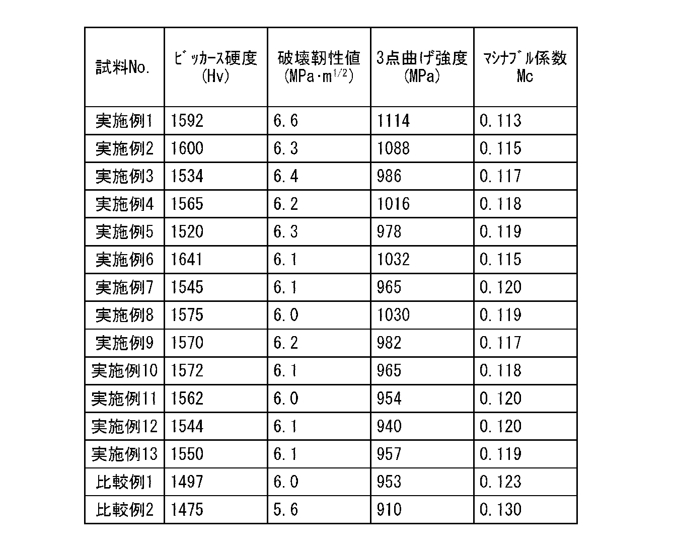
上記各表1-2に示す結果から明らかなように、各実施例に係る窒化珪素焼結体は、ビッカース硬度(Hv)が1500以上であり、破壊靭性値(K1C)が6.0MPa・m1/2以上であり、3点曲げ強度が900MPa以上であり、マシナブル係数Mcが0.100~0.120の範囲内であった。Mcの計算例として実施例1のマシナブル係数は押込み荷重Fn=20kgf、ビッカース硬度Hv=1592、破壊靭性値K1c=6.6MPa・m1/2として、Mc=209/8/(6.61/2・15925/8)より算出された値である。
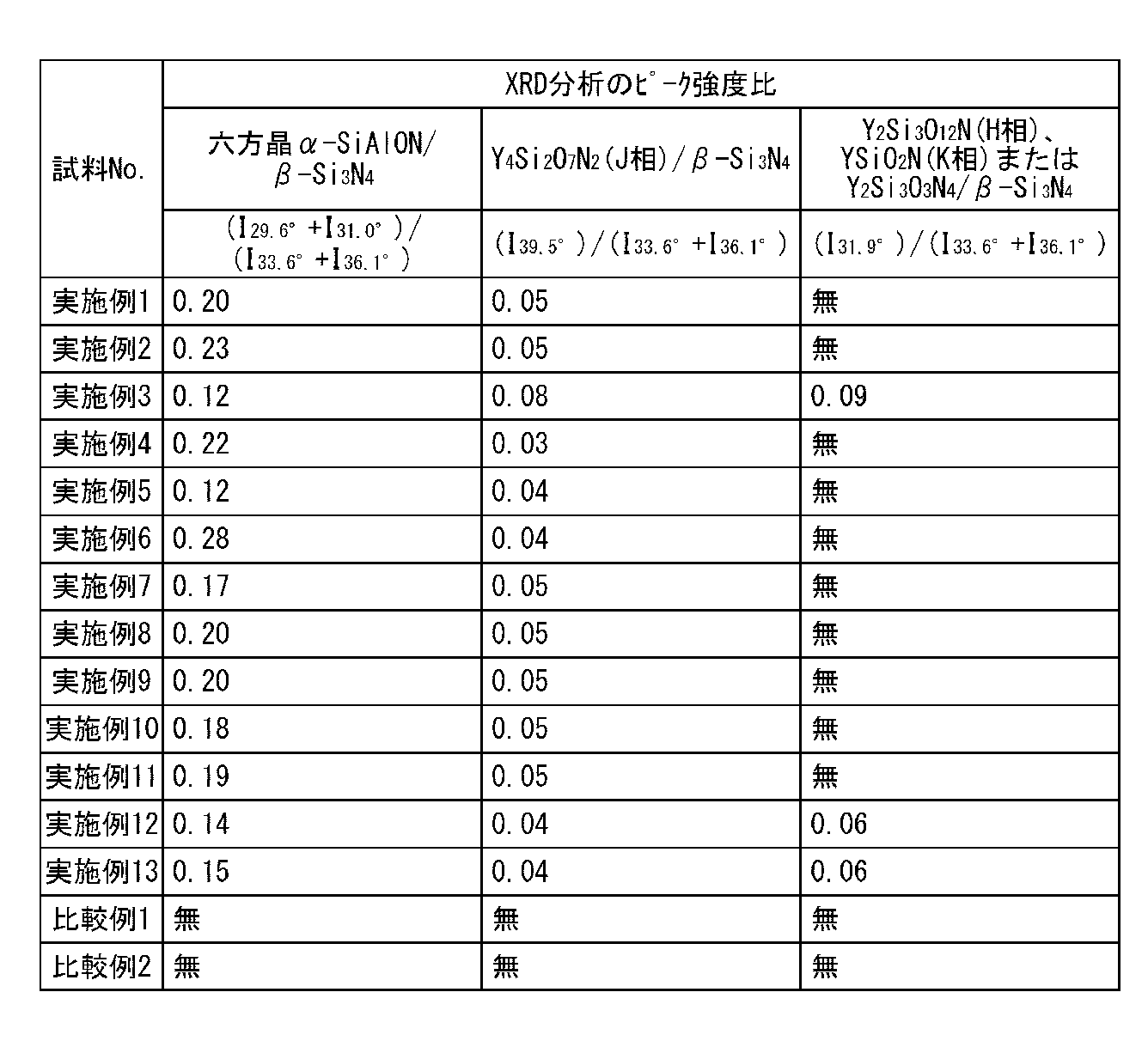
また、断面の研磨面を使ってXRD分析により各結晶のピーク強度比を求めた。その結果を表3に示す。
次に、断面の研磨面のSEM写真を使って単位面積100μm×100μmあたりの粒界相の面積比を求めた。粒界相の面積比は、単位面積100μm×100μmを5か所測定し、上限と下限を記載した。また、TEM分析により、粒界相に「Hf-Y-O系化合物結晶」「Y-Al-O系化合物非晶質相」の有無を調べた。その結果を下記表4に示す。
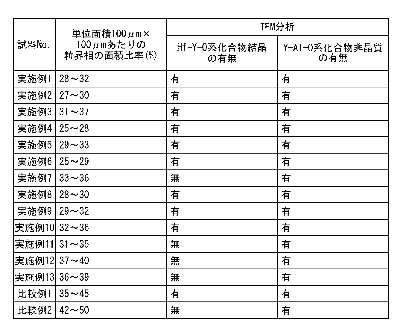
上記表4に示す結果から明らかなように、各実施例に係る窒化珪素焼結体は粒界相の面積比が25~40%の範囲内であった。
(実施例1B~13Bおよび比較例1B~2B)
実施例1~13および比較例1~2と同様の製造方法を用いて摺動部材であるベアリングボールを作製した。ベアリングボールの直径は9.525mm、表面粗さ(Ra)は0.01μmになるように研磨した。
実施例1~13および比較例1~2と同様の製造方法を用いて摺動部材であるベアリングボールを作製した。ベアリングボールの直径は9.525mm、表面粗さ(Ra)は0.01μmになるように研磨した。
研磨加工に関しては、試料として表面粗さ(Ra)は0.01μmに研磨加工する前のものを用意して、ダイヤモンド砥石(#120)を使って研磨加工を行った場合の表面粗さを比較した。研磨加工条件は、試料の加工面積を一定にして荷重を40Nとし、研削盤の回転速度を300rpmとして加工し、表面粗さ(Ra)の変化がなくなる時間まで加工を行った後の、表面粗さ(Ra)を測定した。この研磨加工により脱粒状態を測定できる。脱粒状態は表面粗さに相関性があり、数値が大きいほど脱粒が生じやすいことを意味し、転がり寿命テストにおける信頼性は低下傾向となることが想定される。
また、転がり寿命および転がり寿命の前後での圧砕強度の変化を測定した。転がり寿命および圧砕強度の測定を行うにあたり、ベアリングボールの表面を表面粗さ(Ra)が0.01μmになるように研磨加工した仕上げ加工面を有するものを使用した。
また、転がり寿命は、各実施例に係るベアリングボールを3個用意し、軸受鋼SUJ2の上面に設定した直径40mmの軌道上に上記3個のベアリングボールを等間隔で配置する。これをタービン油の油浴潤滑条件下でベアリングボールに5.9GPaの最大接触応力が作用するように荷重を印加した状態で回転数1200rpmにてベアリングボールの表面が剥離するまでの時間として転がり寿命を測定した。なお、転がり寿命の測定は連続800時間を上限として行った。
また、転がり試験の前後での圧砕強度に関しては2球圧砕法により、ベアリングボールが破壊される荷重を求めた。その結果を表5に示す。
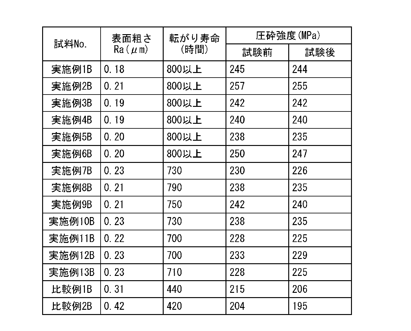
上記表5に示す結果から明らかなように、各実施例に係るベアリングボールは700時間以上の優れた摺動特性を示した。特にHf-Y-O系化合物結晶を具備し、焼結助剤としてMo2Cを添加した実施例1~6は800時間経過後も優れた特性を維持していることが判明した。
ベアリングボールは焼結体の全面を摺動面として使用される摺動部材である。そのため、ベアリングボールとしての特性が優れていれば他の摺動部材に用いたとしても同様に優れた特性を示すものである。従って、実施例の窒化珪素焼結体は様々な摺動部材に適用できる。
なお、本発明のいくつかの実施形態を説明したが、これらの実施形態は例として提示したものであり、発明の範囲を限定することは意図していない。これら新規な実施形態は、その他の様々な形態で実施し得るものであり、発明の要旨を逸脱しない範囲で、種々の省略、置き換え、変更を行うことができる。これら実施形態やその変形は、発明の範囲や要旨に含まれると共に、特許請求の範囲に記載された発明とその均等の範囲に含まれる。
本発明に係る窒化珪素焼結体およびそれを用いた摺動部材によれば、摺動特性に関して長期信頼性を付与できる窒化珪素焼結体を提供できる。また、マシナブル係数を調整してあるので表面研磨加工したとしても、脱粒を小さくできるので平坦な摺動面を得易い。そのため、その焼結体を使用した摺動部材に関しても長期信頼性を得ることができる。
1…ベアリングボール〈窒化珪素焼結体、摺動部材〉
Claims (12)
- 窒化珪素焼結体をXRD分析した際に、六方晶系α-SiAlON結晶に対応する29.6±0.3°および31.0±0.3°に検出される最強ピーク強度をI29.6°、I31.0°とする一方、β-Si3N4結晶に対応する33.6±0.3°、36.1±0.3°に検出される最強ピーク強度をI33.6°、I36.1°としたときに、各最強ピーク強度が下記関係式:
I29.6°+I31.0°)/(I33.6°+I36.1°)=0.10~0.30 …(1)
を満たし、
上記窒化珪素焼結体の任意の断面における単位面積100μm×100μm当りの粒界相の面積比が25~40%であり、マシナブル係数が0.100~0.120であることを特徴とする窒化珪素焼結体。 - 窒化珪素焼結体をXRD分析した際に、Y4Si2O7N2(J相)に対応する39.5±0.3°に検出される最強ピーク強度I39.5°が、下記関係式:
(I39.5°)/(I33.6°+I36.1°)=0.03~0.10 …(2)
を満たすことを特徴とする請求項1記載の窒化珪素焼結体。 - 窒化珪素焼結体をXRD分析した際に、Y2Si3O12N(H相)、YSiO2N(K相)またはY2Si3O3N4のいずれか1種以上に対応する31.9±0.3°に検出される最強ピーク強度I31.9°が、下記関係式:
(I31.9°)/(I33.6°+I36.1°)=0.05~0.15 …(3)
を満たすことを特徴とする請求項1ないし請求項2のいずれか1項に記載の窒化珪素焼結体。 - XRD分析は窒化珪素焼結体の任意の断面にて行うことを特徴とする請求項1ないし請求項3のいずれか1項に記載の窒化珪素焼結体。
- Hf-Y-O系化合物結晶とY-Al-Oとを含有する非晶質相を含む粒界相を具備することを特徴とする請求項1ないし請求項4のいずれか1項に記載の窒化珪素焼結体。
- 平均粒径2μm以下の酸化物、炭化物、窒化物のいずれか1種以上の粒子を具備することを特徴とする請求項1ないし請求項5のいずれか1項に記載の窒化珪素焼結体。
- 前記粒子がモリブデン化合物粒子であることを特徴とする請求項6記載の窒化珪素焼結体。
- Alを酸化物換算値で5~10質量%、希土類元素のいずれか1種類以上を酸化物換算値で1~10質量%、4A、5A、6A元素のいずれか1種類以上を酸化物換算値で1~5質量%含有し、かつ、Alと希土類元素とのmol比がAl(mol):希土類元素(mol)=1:1~8:1であることを特徴とする請求項1ないし請求項7のいずれか1項に記載の窒化珪素焼結体。
- ビッカース硬度(Hv)が1500以上であり、破壊靭性値(K1C)が6.0MPa・m1/2以上であり、かつ、3点曲げ強度が900MPa以上であることを特徴とする請求項1ないし請求項8のいずれか1項に記載の窒化珪素焼結体。
- 請求項1ないし請求項9のいずれか1項に記載の窒化珪素焼結体を用いたことを特徴とする摺動部材。
- 摺動部材がベアリングボールであることを特徴とする請求項10記載の摺動部材。
- 摺動面は表面粗さ(Ra)が0.5μm以下の研磨面であることを特徴とする請求項10ないし請求項11のいずれか1項に記載の摺動部材。
Priority Applications (2)
| Application Number | Priority Date | Filing Date | Title |
|---|---|---|---|
| CN201380057709.9A CN104768900B (zh) | 2012-12-14 | 2013-12-06 | 氮化硅烧结体以及使用该氮化硅烧结体的滑动构件 |
| JP2014552022A JP6334413B2 (ja) | 2012-12-14 | 2013-12-06 | 窒化珪素焼結体およびそれを用いた摺動部材 |
Applications Claiming Priority (2)
| Application Number | Priority Date | Filing Date | Title |
|---|---|---|---|
| JP2012-273964 | 2012-12-14 | ||
| JP2012273964 | 2012-12-14 |
Publications (1)
| Publication Number | Publication Date |
|---|---|
| WO2014092021A1 true WO2014092021A1 (ja) | 2014-06-19 |
Family
ID=50934312
Family Applications (1)
| Application Number | Title | Priority Date | Filing Date |
|---|---|---|---|
| PCT/JP2013/082858 Ceased WO2014092021A1 (ja) | 2012-12-14 | 2013-12-06 | 窒化珪素焼結体およびそれを用いた摺動部材 |
Country Status (3)
| Country | Link |
|---|---|
| JP (1) | JP6334413B2 (ja) |
| CN (1) | CN104768900B (ja) |
| WO (1) | WO2014092021A1 (ja) |
Cited By (7)
| Publication number | Priority date | Publication date | Assignee | Title |
|---|---|---|---|---|
| WO2016117553A1 (ja) * | 2015-01-23 | 2016-07-28 | 株式会社東芝 | 高熱伝導性窒化珪素焼結体、それを用いた窒化珪素基板および窒化珪素回路基板並びに半導体装置 |
| JP2017209716A (ja) * | 2016-05-27 | 2017-11-30 | 日本特殊陶業株式会社 | 摩擦攪拌接合用工具 |
| JP2019198895A (ja) * | 2014-09-25 | 2019-11-21 | 株式会社東芝 | 窒化珪素焼結体製摩擦攪拌接合ツール部材およびそれを用いた摩擦攪拌接合装置 |
| WO2023162746A1 (ja) * | 2022-02-25 | 2023-08-31 | 京セラ株式会社 | 窒化珪素質焼結体 |
| CN117083256A (zh) * | 2022-03-16 | 2023-11-17 | 株式会社东芝 | 氮化硅烧结体及使用了其的耐磨性构件 |
| WO2025041805A1 (ja) * | 2023-08-24 | 2025-02-27 | 株式会社 東芝 | 窒化珪素焼結体およびそれを用いた耐摩耗材部材 |
| WO2025173749A1 (ja) * | 2024-02-15 | 2025-08-21 | 株式会社Niterra Materials | 窒化珪素焼結体およびそれを用いた耐摩耗性部材 |
Families Citing this family (3)
| Publication number | Priority date | Publication date | Assignee | Title |
|---|---|---|---|---|
| CN108840687A (zh) * | 2018-07-26 | 2018-11-20 | 深圳市东川技术研究有限公司 | 一种高强度赛隆新材料的烧结工艺 |
| KR20220034894A (ko) | 2019-07-19 | 2022-03-18 | 에바텍 아크티엔게젤샤프트 | 압전 코팅 및 증착 공정 |
| CN116964021A (zh) * | 2021-03-30 | 2023-10-27 | 株式会社东芝 | 氮化硅烧结体、耐磨性构件及氮化硅烧结体的制造方法 |
Citations (7)
| Publication number | Priority date | Publication date | Assignee | Title |
|---|---|---|---|---|
| JPS59182276A (ja) * | 1983-03-31 | 1984-10-17 | 株式会社東芝 | 窒化ケイ素焼結体 |
| JPS60239365A (ja) * | 1984-04-06 | 1985-11-28 | サントレ−ド リミテイド | 窒化物系セラミツク材料 |
| JPS62275071A (ja) * | 1986-05-22 | 1987-11-30 | 日立金属株式会社 | 強靭性サイアロン |
| JPH0244066A (ja) * | 1988-04-07 | 1990-02-14 | Toyota Central Res & Dev Lab Inc | 窒化珪素質焼結体 |
| JPH04209764A (ja) * | 1990-11-30 | 1992-07-31 | Toyota Central Res & Dev Lab Inc | 窒化珪素質焼結体およびその製造方法 |
| JPH09506852A (ja) * | 1993-12-23 | 1997-07-08 | ザ・ダウ・ケミカル・カンパニー | SiAlON複合体およびそれの製造方法 |
| JP2007130700A (ja) * | 2005-11-08 | 2007-05-31 | Ngk Spark Plug Co Ltd | サイアロン製切削工具及びこれを備えた工具 |
Family Cites Families (2)
| Publication number | Priority date | Publication date | Assignee | Title |
|---|---|---|---|---|
| US8475944B2 (en) * | 2007-06-28 | 2013-07-02 | Kennametal Inc. | Coated ceramic cutting insert and method for making the same |
| JP5268750B2 (ja) * | 2009-04-01 | 2013-08-21 | 株式会社東芝 | 耐衝撃部材およびその製造方法 |
-
2013
- 2013-12-06 CN CN201380057709.9A patent/CN104768900B/zh active Active
- 2013-12-06 WO PCT/JP2013/082858 patent/WO2014092021A1/ja not_active Ceased
- 2013-12-06 JP JP2014552022A patent/JP6334413B2/ja active Active
Patent Citations (7)
| Publication number | Priority date | Publication date | Assignee | Title |
|---|---|---|---|---|
| JPS59182276A (ja) * | 1983-03-31 | 1984-10-17 | 株式会社東芝 | 窒化ケイ素焼結体 |
| JPS60239365A (ja) * | 1984-04-06 | 1985-11-28 | サントレ−ド リミテイド | 窒化物系セラミツク材料 |
| JPS62275071A (ja) * | 1986-05-22 | 1987-11-30 | 日立金属株式会社 | 強靭性サイアロン |
| JPH0244066A (ja) * | 1988-04-07 | 1990-02-14 | Toyota Central Res & Dev Lab Inc | 窒化珪素質焼結体 |
| JPH04209764A (ja) * | 1990-11-30 | 1992-07-31 | Toyota Central Res & Dev Lab Inc | 窒化珪素質焼結体およびその製造方法 |
| JPH09506852A (ja) * | 1993-12-23 | 1997-07-08 | ザ・ダウ・ケミカル・カンパニー | SiAlON複合体およびそれの製造方法 |
| JP2007130700A (ja) * | 2005-11-08 | 2007-05-31 | Ngk Spark Plug Co Ltd | サイアロン製切削工具及びこれを備えた工具 |
Non-Patent Citations (1)
| Title |
|---|
| SHIGETAKA WADA ET AL.: "Erosive wear of .ALPHA.'-.BETA.' sialon composites", JOURNAL OF THE JAPAN SOCIETY OF POWDER AND POWDER METALLURGY, vol. 37, no. 7, 25 September 1990 (1990-09-25), pages 166 - 169 * |
Cited By (12)
| Publication number | Priority date | Publication date | Assignee | Title |
|---|---|---|---|---|
| JP2019198895A (ja) * | 2014-09-25 | 2019-11-21 | 株式会社東芝 | 窒化珪素焼結体製摩擦攪拌接合ツール部材およびそれを用いた摩擦攪拌接合装置 |
| WO2016117553A1 (ja) * | 2015-01-23 | 2016-07-28 | 株式会社東芝 | 高熱伝導性窒化珪素焼結体、それを用いた窒化珪素基板および窒化珪素回路基板並びに半導体装置 |
| JPWO2016117553A1 (ja) * | 2015-01-23 | 2017-11-02 | 株式会社東芝 | 高熱伝導性窒化珪素焼結体、それを用いた窒化珪素基板および窒化珪素回路基板並びに半導体装置 |
| US10308560B2 (en) | 2015-01-23 | 2019-06-04 | Kabushiki Kaisha Toshiba | High thermal conductive silicon nitride sintered body, and silicon nitride substrate and silicon nitride circuit board and semiconductor apparatus using the same |
| JP2017209716A (ja) * | 2016-05-27 | 2017-11-30 | 日本特殊陶業株式会社 | 摩擦攪拌接合用工具 |
| WO2023162746A1 (ja) * | 2022-02-25 | 2023-08-31 | 京セラ株式会社 | 窒化珪素質焼結体 |
| JPWO2023162746A1 (ja) * | 2022-02-25 | 2023-08-31 | ||
| JP7794943B2 (ja) | 2022-02-25 | 2026-01-06 | 京セラ株式会社 | 窒化珪素質焼結体 |
| EP4484400A4 (en) * | 2022-02-25 | 2026-02-18 | Kyocera Corp | SINTERED SILICON NITRIDE BODY |
| CN117083256A (zh) * | 2022-03-16 | 2023-11-17 | 株式会社东芝 | 氮化硅烧结体及使用了其的耐磨性构件 |
| WO2025041805A1 (ja) * | 2023-08-24 | 2025-02-27 | 株式会社 東芝 | 窒化珪素焼結体およびそれを用いた耐摩耗材部材 |
| WO2025173749A1 (ja) * | 2024-02-15 | 2025-08-21 | 株式会社Niterra Materials | 窒化珪素焼結体およびそれを用いた耐摩耗性部材 |
Also Published As
| Publication number | Publication date |
|---|---|
| JP6334413B2 (ja) | 2018-05-30 |
| CN104768900B (zh) | 2016-05-25 |
| JPWO2014092021A1 (ja) | 2017-01-12 |
| CN104768900A (zh) | 2015-07-08 |
Similar Documents
| Publication | Publication Date | Title |
|---|---|---|
| JP6334413B2 (ja) | 窒化珪素焼結体およびそれを用いた摺動部材 | |
| JP6400478B2 (ja) | 耐磨耗性部材 | |
| JP5944910B2 (ja) | 窒化珪素焼結体とその製造方法、およびそれを用いた耐摩耗性部材とベアリング | |
| JP5886337B2 (ja) | 耐摩耗性部材およびそれを用いた耐摩耗性機器 | |
| JP5100201B2 (ja) | 窒化珪素焼結体とそれを用いた摺動部材 | |
| JPWO2011102298A1 (ja) | 耐摩耗性部材およびその製造方法 | |
| JP6491964B2 (ja) | 窒化珪素焼結体およびそれを用いた耐摩耗性部材 | |
| JP2011016716A (ja) | 窒化けい素焼結体 | |
| WO2005030674A1 (ja) | 窒化けい素製耐摩耗性部材およびその製造方法 | |
| JP4693374B2 (ja) | 窒化けい素焼結体の製造方法 | |
| JPWO2008032427A1 (ja) | 摺動部材とそれを用いた軸受 | |
| US9663407B2 (en) | Silicon nitride wear resistant member and method for producing silicon nitride sintered compact | |
| JP5989602B2 (ja) | 窒化珪素質焼結体及びその製造方法、並びにベアリング用転動体 | |
| JP2016104689A (ja) | 窒化珪素質焼結体、その製造方法、及びベアリング用転動体 | |
| JP5349525B2 (ja) | 転動体 | |
| JP7353820B2 (ja) | 窒化珪素焼結体およびそれを用いた耐摩耗性部材 | |
| JP2003300780A (ja) | 窒化けい素製耐摩耗性部材およびその製造方法 | |
| EP4155565A1 (en) | Silicon nitride sintered body, wear-resistant member using same, and method for manufacturing silicon nitride sintered body | |
| JP4939736B2 (ja) | 窒化けい素焼結体の製造方法 | |
| JP2007326745A (ja) | 耐磨耗性部材、耐磨耗性機器および耐磨耗性部材の製造方法 |
Legal Events
| Date | Code | Title | Description |
|---|---|---|---|
| 121 | Ep: the epo has been informed by wipo that ep was designated in this application |
Ref document number: 13863582 Country of ref document: EP Kind code of ref document: A1 |
|
| ENP | Entry into the national phase |
Ref document number: 2014552022 Country of ref document: JP Kind code of ref document: A |
|
| NENP | Non-entry into the national phase |
Ref country code: DE |
|
| 122 | Ep: pct application non-entry in european phase |
Ref document number: 13863582 Country of ref document: EP Kind code of ref document: A1 |