WO2014091759A1 - 光学フィルムとその製造方法、円偏光板および有機el表示装置 - Google Patents
光学フィルムとその製造方法、円偏光板および有機el表示装置 Download PDFInfo
- Publication number
- WO2014091759A1 WO2014091759A1 PCT/JP2013/007300 JP2013007300W WO2014091759A1 WO 2014091759 A1 WO2014091759 A1 WO 2014091759A1 JP 2013007300 W JP2013007300 W JP 2013007300W WO 2014091759 A1 WO2014091759 A1 WO 2014091759A1
- Authority
- WO
- WIPO (PCT)
- Prior art keywords
- optical film
- film
- layer
- cellulose acetate
- group
- Prior art date
- Legal status (The legal status is an assumption and is not a legal conclusion. Google has not performed a legal analysis and makes no representation as to the accuracy of the status listed.)
- Ceased
Links
Images


Classifications
-
- B—PERFORMING OPERATIONS; TRANSPORTING
- B32—LAYERED PRODUCTS
- B32B—LAYERED PRODUCTS, i.e. PRODUCTS BUILT-UP OF STRATA OF FLAT OR NON-FLAT, e.g. CELLULAR OR HONEYCOMB, FORM
- B32B23/00—Layered products comprising a layer of cellulosic plastic substances, i.e. substances obtained by chemical modification of cellulose, e.g. cellulose ethers, cellulose esters, viscose
- B32B23/04—Layered products comprising a layer of cellulosic plastic substances, i.e. substances obtained by chemical modification of cellulose, e.g. cellulose ethers, cellulose esters, viscose comprising such cellulosic plastic substance as the main or only constituent of a layer, which is next to another layer of the same or of a different material
- B32B23/08—Layered products comprising a layer of cellulosic plastic substances, i.e. substances obtained by chemical modification of cellulose, e.g. cellulose ethers, cellulose esters, viscose comprising such cellulosic plastic substance as the main or only constituent of a layer, which is next to another layer of the same or of a different material of synthetic resin
-
- B—PERFORMING OPERATIONS; TRANSPORTING
- B32—LAYERED PRODUCTS
- B32B—LAYERED PRODUCTS, i.e. PRODUCTS BUILT-UP OF STRATA OF FLAT OR NON-FLAT, e.g. CELLULAR OR HONEYCOMB, FORM
- B32B23/00—Layered products comprising a layer of cellulosic plastic substances, i.e. substances obtained by chemical modification of cellulose, e.g. cellulose ethers, cellulose esters, viscose
- B32B23/20—Layered products comprising a layer of cellulosic plastic substances, i.e. substances obtained by chemical modification of cellulose, e.g. cellulose ethers, cellulose esters, viscose comprising esters
-
- B—PERFORMING OPERATIONS; TRANSPORTING
- B32—LAYERED PRODUCTS
- B32B—LAYERED PRODUCTS, i.e. PRODUCTS BUILT-UP OF STRATA OF FLAT OR NON-FLAT, e.g. CELLULAR OR HONEYCOMB, FORM
- B32B27/00—Layered products comprising a layer of synthetic resin
- B32B27/18—Layered products comprising a layer of synthetic resin characterised by the use of special additives
- B32B27/22—Layered products comprising a layer of synthetic resin characterised by the use of special additives using plasticisers
-
- B—PERFORMING OPERATIONS; TRANSPORTING
- B32—LAYERED PRODUCTS
- B32B—LAYERED PRODUCTS, i.e. PRODUCTS BUILT-UP OF STRATA OF FLAT OR NON-FLAT, e.g. CELLULAR OR HONEYCOMB, FORM
- B32B27/00—Layered products comprising a layer of synthetic resin
- B32B27/36—Layered products comprising a layer of synthetic resin comprising polyesters
-
- H—ELECTRICITY
- H10—SEMICONDUCTOR DEVICES; ELECTRIC SOLID-STATE DEVICES NOT OTHERWISE PROVIDED FOR
- H10K—ORGANIC ELECTRIC SOLID-STATE DEVICES
- H10K59/00—Integrated devices, or assemblies of multiple devices, comprising at least one organic light-emitting element covered by group H10K50/00
- H10K59/80—Constructional details
- H10K59/8791—Arrangements for improving contrast, e.g. preventing reflection of ambient light
-
- B—PERFORMING OPERATIONS; TRANSPORTING
- B32—LAYERED PRODUCTS
- B32B—LAYERED PRODUCTS, i.e. PRODUCTS BUILT-UP OF STRATA OF FLAT OR NON-FLAT, e.g. CELLULAR OR HONEYCOMB, FORM
- B32B2250/00—Layers arrangement
- B32B2250/40—Symmetrical or sandwich layers, e.g. ABA, ABCBA, ABCCBA
-
- B—PERFORMING OPERATIONS; TRANSPORTING
- B32—LAYERED PRODUCTS
- B32B—LAYERED PRODUCTS, i.e. PRODUCTS BUILT-UP OF STRATA OF FLAT OR NON-FLAT, e.g. CELLULAR OR HONEYCOMB, FORM
- B32B2307/00—Properties of the layers or laminate
- B32B2307/40—Properties of the layers or laminate having particular optical properties
- B32B2307/42—Polarizing, birefringent, filtering
-
- B—PERFORMING OPERATIONS; TRANSPORTING
- B32—LAYERED PRODUCTS
- B32B—LAYERED PRODUCTS, i.e. PRODUCTS BUILT-UP OF STRATA OF FLAT OR NON-FLAT, e.g. CELLULAR OR HONEYCOMB, FORM
- B32B2307/00—Properties of the layers or laminate
- B32B2307/50—Properties of the layers or laminate having particular mechanical properties
- B32B2307/51—Elastic
-
- B—PERFORMING OPERATIONS; TRANSPORTING
- B32—LAYERED PRODUCTS
- B32B—LAYERED PRODUCTS, i.e. PRODUCTS BUILT-UP OF STRATA OF FLAT OR NON-FLAT, e.g. CELLULAR OR HONEYCOMB, FORM
- B32B2307/00—Properties of the layers or laminate
- B32B2307/50—Properties of the layers or laminate having particular mechanical properties
- B32B2307/54—Yield strength; Tensile strength
-
- B—PERFORMING OPERATIONS; TRANSPORTING
- B32—LAYERED PRODUCTS
- B32B—LAYERED PRODUCTS, i.e. PRODUCTS BUILT-UP OF STRATA OF FLAT OR NON-FLAT, e.g. CELLULAR OR HONEYCOMB, FORM
- B32B2457/00—Electrical equipment
- B32B2457/20—Displays, e.g. liquid crystal displays, plasma displays
- B32B2457/206—Organic displays, e.g. OLED
-
- B—PERFORMING OPERATIONS; TRANSPORTING
- B32—LAYERED PRODUCTS
- B32B—LAYERED PRODUCTS, i.e. PRODUCTS BUILT-UP OF STRATA OF FLAT OR NON-FLAT, e.g. CELLULAR OR HONEYCOMB, FORM
- B32B2551/00—Optical elements
-
- G—PHYSICS
- G02—OPTICS
- G02B—OPTICAL ELEMENTS, SYSTEMS OR APPARATUS
- G02B5/00—Optical elements other than lenses
- G02B5/30—Polarising elements
- G02B5/3025—Polarisers, i.e. arrangements capable of producing a definite output polarisation state from an unpolarised input state
- G02B5/3033—Polarisers, i.e. arrangements capable of producing a definite output polarisation state from an unpolarised input state in the form of a thin sheet or foil, e.g. Polaroid
Definitions
- the present invention relates to an optical film and a manufacturing method thereof, a circularly polarizing plate, and an organic EL display device.
- An organic EL display device for example, a top emission type organic EL display device usually includes an organic EL element in which a metal electrode (cathode), an organic light emitting layer, a transparent electrode (anode), and a transparent substrate are laminated in this order.
- a circularly polarizing plate In order to suppress such a decrease in visibility due to the reflection of external light, it has been studied to provide a circularly polarizing plate on the viewing side of the organic EL element.
- a ⁇ / 4 retardation film constituting the circularly polarizing plate for example, a laminated film of cellulose triacetate (TAC) has been proposed (for example, Patent Document 1).
- TAC / cellulose acetate propionate (CAP) / TAC laminated film for example, Patent Document 2
- CAP laminated film for example, Patent Document 3
- a laminated film of TAC for example, Patent Document 4
- JP 2003-014933 A JP 2011-158839 A JP 2002-265638 A JP 2001-131301 A
- the main component thereof is cellulose diacetate (DAC) having a high retardation development property, and cellulose acetate propionate which is easily stretched at a high magnification (CAP) is considered preferable.
- DAC cellulose diacetate
- CAP cellulose acetate propionate which is easily stretched at a high magnification
- the present inventors have found that the film surface containing CAP or DAC as a main component is more easily destroyed by saponification with an aqueous alkaline solution than the film containing TAC as a main component. It was found by observation of the film surface. Specifically, the destruction of the film surface means that a film containing CAP or DAC as a main component contains a relatively larger amount of hydroxyl groups than a film containing TAC as a main component. It is thought that it is caused by excessive hydrolysis of the cellulose ester. Therefore, it has been found that the film mainly composed of CAP and DAC is inferior in adhesiveness to the polarizer of the saponified film than the film mainly composed of TAC.
- a laminated film having a base material layer mainly composed of CAP or DAC and a surface layer mainly composed of TAC has a polarizing layer because the surface layer mainly composed of TAC is not easily damaged by saponification. It is thought that the adhesion with the child can be improved.
- the present invention has been made in view of the above circumstances, and provides an optical film that has few cracks caused by oblique stretching, has good flatness, and can suppress wrinkles in an oblique direction that occur when an organic EL display device is bent. With the goal.
- An optical film for an organic EL display device comprising a cellulose acetate having a degree of substitution of more than 2.6 and not more than 3.0 and a surface layer containing a plasticizer, and an in-plane slow axis direction of the optical film Is an oblique direction with respect to the width direction of the film, and the ratio X / Y of the tensile elastic modulus X in the slow axis direction to the tensile elastic modulus Y in the direction orthogonal to the slow axis direction is 1.5 or more
- the optical film which is 5.0 or less and the mass ratio of the amount of the plasticizer contained in the surface layer to the amount of the plasticizer contained in the base material layer is 1.2 times or more and 5.5 times or less
- the cellulose acetate propionate contained in the base material layer or cellulose acetate having a substitution degree of acetyl group of 2.0 or more and 2.6 or less has a weight average molecular weight Mw of 150,000 to 300,000 and a number average
- the optical film according to any one of [1] to [5], wherein the plasticizer contained in the surface layer is a polyester compound obtained by a polycondensation reaction between a diol and a dicarboxylic acid.
- the optical film according to [6] wherein the polyester compound has a weight average molecular weight of 700 to 2,000.
- the optical film has a retardation Ro in the in-plane direction at a wavelength of 550 nm defined by the formula (I) in the range of 120 to 180 nm, defined by the formula (II), and in the thickness direction at the wavelength of 550 nm.
- the step of obtaining the laminated film includes cellulose acetate propionate or cellulose acetate having a substitution degree of acetyl group of 2.0 or more and 2.6 or less, a first layer dope containing a plasticizer and an organic solvent.
- Obtaining a second layer dope containing cellulose acetate having a substitution degree of acetyl group of more than 2.6 and not more than 3.0, a plasticizer and an organic solvent; and the second layer dope and the second dope A step of casting the layer dope simultaneously or sequentially on the casting support; and the organic solvent contained in the laminated first layer dope and the second layer dope.
- an optical film that has few cracks caused by oblique stretching and can suppress wrinkles in an oblique direction that occurs when the organic EL display device is bent.
- optical film of the present invention comprises a substrate layer and at least one surface thereof; preferably a surface layer disposed on both surfaces.
- the optical film of the present invention is preferably used as an optical film constituting a circularly polarizing plate of an organic EL display device.
- the base material layer contains cellulose acetate propionate A1 or cellulose acetate A2 having a substitution degree of acetyl group of 2.0 or more and 2.6 or less, and a plasticizer.
- the cellulose acetate propionate A1 contained in the base material layer is a cellulose ester in which an acyl group is composed of a propionyl group and an acetyl group.
- the total substitution degree of the acyl group of cellulose acetate propionate A1 is preferably 2.0 or more and 3.0 or less, more preferably 2.2 or more and 2.9 or less, and 2.4 or more and 2. It is more preferably 8 or less, and particularly preferably 2.4 or more and 2.5 or less.
- the total substitution degree of the acyl group is low, the expression of retardation Ro in the in-plane direction is high, but the wavelength dispersion characteristic of Ro tends to be flat.
- the total substitution degree of the acyl group is high, the expression of retardation Ro in the in-plane direction is low, but the wavelength dispersion characteristic of Ro tends to be reverse dispersion.
- the degree of substitution of the propionyl group of cellulose acetate propionate A1 is preferably 0.5 or more, and more preferably 0.8 or more in order to make the stretchability of the film constant or more.
- the substitution degree of the propionyl group is preferably 1.5 or less, and more preferably 1.0 or less.
- the method for measuring the total degree of acyl group substitution can be measured according to ASTM-D817-96.
- the cellulose acetate A2 contained in the base material layer is a cellulose ester in which all of the acyl groups are acetyl groups, and the total substitution degree of the acyl groups (acetyl substitution degree) is 2.0 or more and 2.6 or less.
- the total substitution degree (acyl group substitution degree) of the acyl group of cellulose acetate A2 is more preferably 2.2 or more and 2.5 or less in order to obtain a certain retardation or more.
- the weight average molecular weight Mw of cellulose acetate propionate A1 and cellulose acetate A2 is preferably 120,000 to 350,000, and preferably 150,000 to 300,000 in order to easily form a film and obtain the mechanical strength of the film. It is preferable that the average particle diameter is 18 to 250,000. Further, the number average molecular weight Mn of cellulose acetate propionate A1 and cellulose acetate A2 is preferably 40,000 to 210,000, preferably 50,000 to 200,000, and preferably 60,000 to 100,000. More preferred.
- the molecular weight distribution (weight average molecular weight Mw / number average molecular weight Mn) of cellulose acetate propionate A1 and cellulose acetate A2 is preferably 1.0 to 3.0. More preferably, it is 2.2 or more and 2.9 or less.
- the weight average molecular weights of cellulose acetate propionate A1 and cellulose acetate A2 can be measured by gel permeation chromatography (GPC).
- the measurement conditions are as follows. Solvent: Methylene chloride Column: Three Shodex K806, K805, K803G (manufactured by Showa Denko KK) are connected and used.
- cellulose acetate propionate A1 contains a propionyl group
- the stretchability is relatively high.
- all of the acyl groups of the cellulose acetate A2 are acetyl groups and have a low degree of substitution, the phase difference developability due to stretching is high. Therefore, cellulose acetate propionate A1 and cellulose acetate A2 are both suitable as optical films for organic EL display devices having a certain retardation or more.
- Plasticizers contained in the base material layer include polyester compounds, sugar ester compounds, ester compounds (including fatty acid ester compounds and phosphate ester compounds), polyhydric alcohol ester compounds, polycarboxylic acid ester compounds (phthalate ester compounds) And a glycolate compound.
- a polyester compound is preferable from the viewpoint of high compatibility with the cellulose ester and improvement in mechanical strength.
- the polyester compound contains a repeating unit derived from a condensate of dicarboxylic acid and diol.
- the dicarboxylic acid constituting the polyester compound can be an aliphatic dicarboxylic acid, an alicyclic dicarboxylic acid, or an aromatic dicarboxylic acid.
- the carbon number of the aliphatic dicarboxylic acid is preferably 4 to 20, and more preferably 4 to 12.
- Examples of the aliphatic dicarboxylic acid include malonic acid, succinic acid, glutaric acid, adipic acid, pimelic acid, suberic acid, azelaic acid, sebacic acid, undecanedicarboxylic acid, dodecanedicarboxylic acid and the like.
- the carbon number of the aromatic dicarboxylic acid is preferably 8 to 20, and more preferably 8 to 12.
- aromatic dicarboxylic acids include 1,2-benzenedicarboxylic acid (phthalic acid), 1,3-benzenedicarboxylic acid (isophthalic acid), 1,4-benzenedicarboxylic acid (terephthalic acid), 1,5-naphthalene Dicarboxylic acid, 1,4-xylidene dicarboxylic acid and the like are included, and 1,4-benzenedicarboxylic acid (terephthalic acid) is preferable.
- the carbon number of the alicyclic dicarboxylic acid is preferably 6 to 20, and more preferably 6 to 12.
- Examples of the alicyclic dicarboxylic acid include 1,3-cyclobutane dicarboxylic acid, 1,3-cyclopentane dicarboxylic acid, 1,4-cyclohexane dicarboxylic acid, 1,4-cyclohexane diacetic acid and the like.
- the dicarboxylic acid constituting the polyester compound may be one type or two or more types.
- the dicarboxylic acid constituting the polyester compound preferably contains an aromatic dicarboxylic acid in order to enhance the compatibility with the cellulose ester; and in order to impart flexibility, it preferably contains an aliphatic dicarboxylic acid.
- the dicarboxylic acid constituting the polyester compound preferably contains both an aromatic dicarboxylic acid and an aliphatic dicarboxylic acid.
- the molar ratio of aromatic dicarboxylic acid to aliphatic dicarboxylic acid can be in the range of 5/95 to 95/5, preferably in the range of 30/70 to 70/30.
- the diol constituting the polyester compound can be an aliphatic diol, an alkyl ether diol, an alicyclic diol, or an aromatic diol.
- the carbon number of the aliphatic diol is preferably 2 to 20, more preferably 2 to 12, and further preferably 2 to 4.
- aliphatic diols examples include ethylene glycol, 1,2-propylene glycol, 1,3-propylene glycol, 1,2-butanediol, 1,3-butanediol, 1,2-propanediol, 2-methyl- 1,3-propanediol, 1,4-butanediol, 1,5-pentanediol, 2,2-dimethyl-1,3-propanediol (neopentyl glycol), 2,2-diethyl-1,3-propane Diol (3,3-dimethylolpentane), 2-n-butyl-2-ethyl-1,3-propanediol (3,3-dimethylolheptane), 3-methyl-1,5-pentanediol, 1, 6-hexanediol, 2,2,4-trimethyl-1,3-pentanediol, 2-ethyl-1,3-hexanediol
- the carbon number of the alkyl ether diol is preferably 4 to 20, and more preferably 4 to 12.
- Examples of the alkyl ether diol include polytetramethylene ether glycol, polyethylene ether glycol and polypropylene ether glycol.
- the carbon number of the alicyclic diol is preferably 4 to 20, and more preferably 4 to 12.
- Examples of the alicyclic diol include 1,4-cyclohexanediol, 1,4-cyclohexanedimethanol and the like.
- the carbon number of the aromatic diol is preferably 6 to 20, and more preferably 6 to 12.
- aromatic diols include 1,2-dihydroxybenzene (catechol), 1,3-dihydroxybenzene (resorcinol), 1,4-dihydroxybenzene (hydroquinone), and the like.
- the diol constituting the polyester compound may be one type or two or more types.
- the diol constituting the polyester compound preferably contains an aliphatic diol.
- the molecular terminal of the polyester compound may be sealed with monocarboxylic acid or monoalcohol as necessary.
- the monocarboxylic acid can be an aliphatic monocarboxylic acid, an alicyclic monocarboxylic acid or an aromatic monocarboxylic acid.
- the carbon number of the aliphatic monocarboxylic acid can be preferably 2 to 30, more preferably 2 to 4.
- Examples of the aliphatic carboxylic acid include acetic acid, propionic acid, butanoic acid, caprylic acid, caproic acid, decanoic acid, dodecanoic acid, stearic acid, oleic acid and the like.
- Examples of the alicyclic monocarboxylic acid include cyclohexyl monocarboxylic acid.
- aromatic monocarboxylic acids examples include benzoic acid, para-tert-butyl benzoic acid, orthotoluic acid, metatoluic acid, p-toluic acid, dimethyl benzoic acid, ethyl benzoic acid, normal propyl benzoic acid, aminobenzoic acid, acetoxybenzoic acid, Phenylacetic acid, 3-phenylpropionic acid and the like are included.
- the monoalcohol can be an aliphatic monoalcohol, an alicyclic monoalcohol or an aromatic monoalcohol.
- the aliphatic monoalcohol has 1 to 30 carbon atoms, preferably 1 to 3 carbon atoms.
- Examples of aliphatic monoalcohols are methanol, ethanol, propanol, isopropanol, butanol, isobutanol, pentanol, isopentanol, hexanol, isohexanol, octanol, isooctanol, 2-ethylhexyl alcohol, nonyl alcohol, isononyl alcohol Tert-nonyl alcohol, decanol, dodecanol, dodecahexanol, dodecaoctanol, allyl alcohol, oleyl alcohol and the like.
- Examples of the alicyclic monoalcohol include cyclohexyl alcohol and the like
- the molecular terminal of the polyester compound is unsealed or is sealed with an aliphatic monocarboxylic acid (preferably acetic acid); More preferably, it is sealed with a monocarboxylic acid (preferably acetic acid).
- the weight average molecular weight of the polyester compound is preferably 500 to 2000, and more preferably 700 to 2000. If the weight average molecular weight is too small, bleeding out may occur. If the weight average molecular weight is too large, the compatibility with the cellulose ester may be lowered.
- polyester compound having a ring structure examples include the following.
- TPA terephthalic acid
- PA phthalic acid
- SA succinic acid
- AA adipic acid
- SEA sebacic acid
- the sugar ester compound is preferably a compound represented by the following formula (FA).
- R 1 to R 8 in the formula (FA) each represents a substituted or unsubstituted alkylcarbonyl group or a substituted or unsubstituted arylcarbonyl group.
- R 1 to R 8 may be the same as or different from each other.
- the substituted or unsubstituted alkylcarbonyl group is preferably a substituted or unsubstituted alkylcarbonyl group having 2 or more carbon atoms.
- Examples of the substituted or unsubstituted alkylcarbonyl group include a methylcarbonyl group (acetyl group) and an ethylcarbonyl group.
- Examples of the substituent that the alkyl group has include an aryl group such as a phenyl group.
- the substituted or unsubstituted arylcarbonyl group is preferably a substituted or unsubstituted arylcarbonyl group having 7 or more carbon atoms.
- the arylcarbonyl group include a phenylcarbonyl group.
- the substituent that the aryl group has include an alkyl group such as a methyl group.
- R represents R 1 to R 8 in the formula (FA).
- the ester compound includes a fatty acid ester compound, a citrate ester compound, a phosphate ester compound, and the like.
- the fatty acid ester compound include butyl oleate, methylacetyl ricinoleate, and dibutyl sebacate.
- the citrate ester compound include acetyltrimethyl citrate, acetyltriethyl citrate, and acetyltributyl citrate.
- phosphate ester compound examples include triphenyl phosphate, tricresyl phosphate, cresyl diphenyl phosphate, octyl diphenyl phosphate, biphenyl diphenyl phosphate, trioctyl phosphate, tributyl phosphate, etc., preferably triphenyl phosphate .
- plasticizers may be used alone or in combination of two or more.
- the content of the plasticizer in the base material layer may be a range in which the ratio of the content of the plasticizer in the surface layer / the content of the plasticizer in the base material layer falls within the range described later, and is preferably the cellulose ester It is 1 to 45% by mass, and more preferably 1.5 to 40% by mass. If the content of the plasticizer is less than 1% by mass, the effect of imparting plasticity may not be sufficient. From the viewpoint of reducing the moisture permeability of the film, the plasticizer content is preferably 20% by mass or more. On the other hand, when the content of the plasticizer is more than 45% by mass, the plasticizer may ooze out from the optical film.
- the base material layer may further contain a wavelength dispersing agent, an ultraviolet absorber, a matting agent, a retardation adjusting agent, a deterioration preventing agent and the like as required.
- the wavelength dispersing agent contained in the base material layer is preferably a compound represented by the following general formula (A).
- L 1 and L 2 each independently represent a single bond or a divalent linking group.
- R 1 , R 2 and R 3 each independently represent a substituent.
- n represents an integer from 0 to 2.
- Wa and Wb each represent a hydrogen atom or a substituent. Wa and Wb may combine with each other to form a ring; at least one of Wa and Wb may have a ring structure; at least one of Wa and Wb is an alkenyl group or an alkynyl group; Also good.
- substituent represented by Wa and Wb include halogen atoms (eg, fluorine atom, chlorine atom, bromine atom, iodine atom), alkyl groups (eg, methyl group, ethyl group, n-propyl group, Isopropyl group, tert-butyl group, n-octyl group, 2-ethylhexyl group, etc.), cycloalkyl group (for example, cyclohexyl group, cyclopentyl group, 4-n-dodecylcyclohexyl group, etc.), alkenyl group (for example, vinyl group, Allyl group), cycloalkenyl group (eg 2-cyclopenten-1-yl, 2-cyclohexen-1-yl group, etc.), alkynyl group (eg ethynyl group, propargyl group etc.), aryl group (eg phenyl group) ,
- R 4 , R 5 and R 6 each represent a hydrogen atom or a substituent.
- substituents include the same groups as the specific examples of the substituent represented by R 1 , R 2 and R 3 .
- the ring formed by bonding of Wa and Wb to each other is preferably a nitrogen-containing 5-membered ring or a sulfur-containing 5-membered ring.
- the compound in which Wa and Wb are bonded to each other to form a ring is preferably a compound represented by the following general formula (1).
- a 1 and A 2 in the general formula (1) each independently represent O, S, NR X (R X represents a hydrogen atom or a substituent) or CO.
- R X represents a hydrogen atom or a substituent
- Examples of the substituent represented by R X has the same meaning as specific examples of substituents represented by the Wa and Wb.
- R X is preferably a hydrogen atom, an alkyl group, an aryl group, or a heterocyclic group.
- X in the general formula (1) may be a non-metal atom of Group 14 to 16 after the third period, or a substituent containing a non-metal atom of Group 14 to 16 or a conjugated system after the third period.
- X is preferably O, S, NRc, or C (Rd) Re.
- Rc, Rd and Re represent substituents, and specific examples of the substituents represented by Wa and Wb are given as examples.
- L 1, L 2, R 1 , R 2, R 3 and n in the general formula (1) is a L 1, L 2, R 1 , R 2, R 3 and n as defined in formula (A) .
- the content of the wavelength dispersing agent contained in the base material layer is preferably 0.5 to 15% by mass with respect to the cellulose ester contained in the base material layer in order to impart desired wavelength dispersibility.
- the content is more preferably 1 to 10% by mass, and further preferably 2 to 6% by mass.
- the ultraviolet absorber contained in the base material layer a compound that is excellent in the ability to absorb ultraviolet rays having a wavelength of 370 nm or less and that has good liquid crystal display properties and that absorbs less visible light having a wavelength of 400 nm or more is preferably used.
- the ultraviolet absorber include hindered phenol compounds, oxybenzophenone compounds, benzotriazole compounds, salicylic acid ester compounds, benzophenone compounds, cyanoacrylate compounds, nickel complex compounds, and the like.
- ultraviolet absorber examples include the following UV-1 to UV-3.
- the content of the ultraviolet absorber is preferably 1 ppm to 1.0% by mass relative to the cellulose ester, more preferably 10 to 1000 ppm.
- the optical film of the present invention may further contain a matting agent (fine particles) in order to improve the surface slipperiness.
- Matting agents (fine particles) contained in the base material layer are silicon dioxide, titanium dioxide, aluminum oxide, zirconium oxide, calcium carbonate, kaolin, talc, calcined calcium silicate, hydrated calcium silicate, aluminum silicate, magnesium silicate Inorganic fine particles such as calcium phosphate, and organic fine particles such as a crosslinked polymer. Among these, fine particles of silicon dioxide are preferable because the haze increase of the film is small.
- the primary average particle diameter of the fine particles is preferably 20 nm or less, preferably 5 to 18 nm, and more preferably 5 to 16 nm.
- the primary particle diameter of the fine particles can be obtained as an average value of the particle diameters of 100 primary particles by observing the primary particles with a transmission electron microscope at a magnification of 500,000 to 2,000,000 times.
- the content of fine particles in the base material layer can be 0.05 to 1.0% by mass, preferably 0.1 to 0.8% by mass with respect to the cellulose ester contained in the base material layer.
- the surface layer contains cellulose acetate B having a substitution degree of acetyl group of more than 2.6 and 3.0 or less, and a plasticizer.
- Cellulose acetate B contained in the surface layer is a cellulose ester in which all of the acyl groups are acetyl groups, and the total substitution degree of the acyl groups (substitution degree of acetyl groups) is more than 2.6 and not more than 3.0. Since the surface of such a film containing cellulose acetate B as a main component is not easily broken by saponification with an alkaline aqueous solution, the adhesion between the polarizer and the optical film can be improved.
- the total substitution degree of the acyl group of cellulose acetate B is preferably 2.65 or more and 2.95 or less, more preferably 2.7 or more and 2.95 or less.
- plasticizer contained in the surface layer examples include the same plasticizers contained in the base material layer. Especially, since the compatibility with cellulose acetate B is favorable, the above-mentioned polyester compound and phosphoric acid ester compound are preferable, and the above-mentioned polyester compound is more preferable.
- the dicarboxylic acid constituting the polyester compound contained in the surface layer is to add flexibility and suppress cracks, and to improve compatibility with the cellulose ester, both aromatic dicarboxylic acid and aliphatic dicarboxylic acid are used. It is preferable to include.
- the molecular terminal of the polyester compound contained in the surface layer may be sealed as described above.
- the molecular end of the polyester compound is preferably unsealed or preferably sealed with an aliphatic monocarboxylic acid (preferably acetic acid); an aliphatic monocarboxylic acid More preferably, it is sealed with (preferably acetic acid).
- the weight average molecular weight of the polyester compound contained in the surface layer is preferably 500 to 2000, and more preferably 700 to 2000. If the weight average molecular weight is too small, bleeding out may occur. If the weight average molecular weight is too large, the compatibility with the cellulose ester may be lowered.
- the optical film of the present invention functions as a ⁇ / 4 retardation film of a circularly polarizing plate of an organic EL display device as will be described later. Therefore, the optical film of this invention is obtained through the process of extending
- cracks may occur in the surface layer of the obtained optical film.
- the organic EL display device having the optical film is folded, wrinkles in an oblique direction may occur in the optical film.
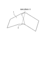
- FIG. 1 is a schematic view showing an example of an oblique wrinkle generated in an optical film when an organic EL display device is bent. As shown in FIG. 1, wrinkles occur in an oblique direction (slow axis direction) with respect to the bending axis C of the optical film 1.
- the cause of the occurrence of wrinkles in the oblique direction due to such bending is not necessarily clear, but is estimated as follows. That is, 1) the film after being stretched at a high magnification in an oblique direction due to the relatively high tensile elastic modulus of the laminated film being stretched, 2) the tensile elastic modulus of each layer of the laminated film being stretched being different, etc. It is thought that distortion tends to remain in the film. It is considered that when the film is bent, wrinkles are generated in an oblique direction in the bent portion due to the distortion remaining in the stretched film.
- a plasticizer to the surface layer and the base material layer of the laminated film.
- the content of the plasticizer in the surface layer is preferably 15 to 50% by mass and more preferably 25 to 45% by mass with respect to the cellulose ester.
- the wrinkles in the oblique direction at the time of bending as described above may not be sufficiently suppressed only by reducing the tensile elastic modulus of the laminated film to be stretched. That is, in order to sufficiently suppress wrinkles in an oblique direction during bending, not only 1) lowering the tensile elastic modulus of the laminated film to be stretched; 2) the tensile elastic modulus of each layer of the laminated film to be stretched It is important to reduce the difference.
- the absolute value of the difference in tensile elastic modulus between the surface layer and the base material layer is preferably 1 GPa or less, and more preferably 0.5 GPa or less.
- the tensile elastic modulus of the surface layer and the base material layer can be measured using Tensilon RTC-1225A manufactured by Orientec Co. in accordance with JIS K7127.
- the measurement conditions may be a distance between chucks of 50 mm under 23 ° C. and 50% RH.
- the difference in tensile elastic modulus between the surface layer and the base material layer can be preferably adjusted by the ratio between the amount of plasticizer contained in the surface layer and the amount of plasticizer contained in the base material layer. That is, the amount of the plasticizer contained in the surface layer is preferably larger than the amount of the plasticizer contained in the base material layer, and preferably 1.2 times or more the amount of the plasticizer contained in the base material layer. 1.4 times or more is more preferable. Even if the amount of the plasticizer contained in the surface layer is too much relative to the amount of the plasticizer contained in the base material layer, the difference in tensile modulus between the surface layer and the base material layer may not be reduced. Therefore, the amount of the plasticizer contained in the surface layer is preferably 5 times or less, more preferably 2.5 times or less of the amount of the plasticizer contained in the base material layer.
- a plasticizer is contained in both the surface layer and the base material layer (preferably the amount of plasticizer contained in the surface layer is set to a certain level or more) and is contained in the surface layer It is preferable that the ratio (mass ratio) of the plasticizer amount to the plasticizer amount contained in the base material layer is a certain level or more.
- the surface layer may further contain the same additive as the base material layer as necessary.
- the substrate layer and the surface layer may each be a single layer or two or more layers.
- the optical film preferably has one base material layer and two surface layers sandwiching the base material layer (having a three-layer structure) in order to reduce the film thickness and to prevent distortion. .
- the total thickness of the optical film is preferably 10 to 250 ⁇ m, more preferably 15 to 100 ⁇ m, and still more preferably 20 to 80 ⁇ m, in order to obtain a sufficient retardation as a ⁇ / 4 retardation film. Particularly preferably, it may be 25 to 65 ⁇ m.
- the ratio of the thickness of the base material layer to the total thickness of the optical film is preferably in the range of 30 to 90%, more preferably 50 to 85%. If the thickness ratio of the base material layer is too low, the retardation of the optical film may not be sufficient. If the thickness ratio of the base material layer is too high, breakage due to saponification of the optical film surface may not be sufficiently suppressed.
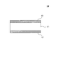
- FIG. 2 is a schematic diagram showing an example of a preferable laminated structure of the optical film.
- the optical film 10 includes a base material layer 11 and a pair of surface layers 13 and 13 ′ that sandwich the base material layer 11.
- compositions and thicknesses of the surface layers 13 and 13 ′ may be the same or different from each other. However, in order to suppress warping of the film, the compositions and thicknesses of the surface layers 13 and 13 ′ may be the same. preferable.
- optical film In-plane slow axis
- a polarizer usually has an absorption axis in the longitudinal direction. Therefore, in the film plane, the optical film has a slow axis in an oblique direction with respect to the width direction (or longitudinal direction) of the film; preferably 40 to 50 °; more preferably 45 ⁇ 2 °.
- the in-plane slow axis of the optical film is an axis in the direction in which the refractive index is maximum in the film plane; it can be measured by an automatic birefringence meter AxoScan or the like.
- the optical film of the present invention is obtained through a step of stretching at a high magnification in an oblique direction in order to obtain a sufficient retardation as a ⁇ / 4 retardation film. Therefore, the tensile modulus of elasticity of the optical film of the present invention; that is, the in-plane slow axis direction is high.
- the ratio X / Y of the tensile elastic modulus X in the in-plane slow axis direction to the tensile elastic modulus Y in the direction orthogonal thereto is preferably 1.5 or more and 5.0 or less, more preferably It may be 1.6 or more and 3.0 or less, more preferably 1.7 or more and 2.5 or less.
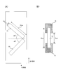
- FIG. 3 is a schematic diagram showing a method for measuring the tensile elastic modulus.
- FIG. 3 illustrates an example in which the slow axis of the optical film is + 45 ° with respect to the TD direction.
- the sample film S1 is cut into a size of 1 cm ⁇ 10 cm parallel to the slow axis direction of the optical film (in FIG. 3A, + 45 ° direction with respect to the TD direction).
- the sample film S2 is cut to a size of 1 cm ⁇ 10 cm parallel to the direction orthogonal to the slow axis direction of the optical film (in FIG. 3A, the direction of ⁇ 45 ° to the TD direction).
- the sample films S1 and S2 are conditioned for 24 hours in an environment of 25 ° C. and 55% RH. 2)
- the sample film S1 after humidity adjustment was set in a tensile tester 15 (Tensilon RTC-1225A manufactured by Orientec Co., Ltd.) and the distance between chucks was set to 50 mm. Based on K7127, the sample film is pulled in the longitudinal direction, and the tensile elastic modulus X is measured.
- the tensile modulus Y is measured by pulling the sample film S2 in the longitudinal direction. The tensile modulus can be measured at 25 ° C. and 55% RH.
- the retardation Ro (550) in the in-plane direction measured at a wavelength of 550 nm in an environment of 23 ° C. and 55% RH is preferably in the range of 120 to 180 nm, preferably 120 to 160 nm. More preferably, it is within the range, and further preferably within the range of 130 to 150 nm.
- the retardation Rth in the thickness direction is preferably 40 to 120 nm, and more preferably 50 to 100 nm.
- An optical film having such a retardation is suitable, for example, as a ⁇ / 4 retardation film for a circularly polarizing plate.
- Retardation Ro and Rth are defined by the following equations, respectively.
- Formula (I) Ro (nx ⁇ ny) ⁇ d
- Formula (II) Rth ⁇ (nx + ny) / 2 ⁇ nz ⁇ ⁇ d (Nx: refractive index in the slow axis direction x in the film plane, ny: refractive index in the direction y perpendicular to the slow axis direction x in the film plane, nz: refractive index in the thickness direction z of the film, d: Film thickness (nm))
- Retardation Ro and Rth can be measured, for example, by the following method. 1) Condition the optical film at 23 ° C. and 55% RH. The average refractive index of the optical film after humidity adjustment is measured with an Abbe refractometer or the like. 2) The Ro when the light having a measurement wavelength of 550 nm is incident on the optical film after humidity adjustment in parallel to the normal line of the film surface is measured with an AxoScan manufactured by Axometric.
- nx, ny and nz are calculated from the measured Ro and R ( ⁇ ) and the above-mentioned average refractive index and film thickness by AxoScan manufactured by Axometric, and Rth at a measurement wavelength of 590 nm is calculated. .
- the measurement of retardation can be performed under conditions of 23 ° C. and 55% RH.
- the internal haze of the optical film measured according to JIS K-7136 is preferably 0.01 to 0.1.
- the visible light transmittance of the optical film is preferably 90% or more, and more preferably 93% or more.
- the optical film of the present invention is 1) a first layer (layer serving as a base material layer) containing the above-mentioned cellulose acetate propionate A1 or cellulose acetate A2 and a plasticizer, and at least one of them.
- a step of obtaining a laminated film comprising a second layer (layer that becomes a surface layer) containing cellulose acetate B and a plasticizer; 2) at least obliquely with respect to the width direction It can be obtained through a step of obtaining an optical film including the base material layer and the surface layer by stretching at a magnification of 1.5 times or more and 3.0 times or less.
- the step of obtaining a laminated film is preferably performed by a co-casting method because it is relatively easy to manufacture.
- the co-casting method may be a solution casting method or a melt casting method, and since an optical film having a good surface shape can be easily obtained, the solution casting method may be preferable.
- the step of obtaining a laminated film is as follows: 1-1) the first dope (the base layer dope) containing the cellulose acetate propionate A1 or cellulose acetate A2, the plasticizer and the organic solvent.
- Step for preparing a dope A cellulose ester, a plasticizer, and, if necessary, other components are dissolved in an organic solvent, and a first dope mainly composed of cellulose ester (dope for base material layer) A second dope (surface layer dope) is obtained.
- the organic solvent used for the preparation of the dope may be a conventionally known organic solvent.
- a solubility parameter in the range of 17 to 22 is preferable. Solubility parameters are described in, for example, J. Brandrup, E.I. “Polymer Handbook (4th. Edition)” such as H, and the like described in VII / 671 to VII / 714.
- the organic solvent may be used alone or in combination of two or more. When combining two or more types, it is preferable to use a mixture of a good solvent and a poor solvent in order to stably obtain an optical film having a good surface shape.
- the mixing ratio of the good solvent and the poor solvent is preferably 60 to 99% by mass for the good solvent and 40 to 1% by mass for the poor solvent.
- a good solvent is one that dissolves the resin used alone, and a poor solvent is one that swells or does not dissolve the resin used alone.
- good solvents include organic halogen compounds such as methylene chloride and dioxolanes.
- the poor solvent methanol, ethanol, n-butanol, cyclohexane and the like are preferably used.
- the poor solvent contained in the first and second dopes is preferably alcohol, and preferably methanol, in order to shorten the drying time of the dope on the casting support.
- the content of methanol in the organic solvent contained in the base layer dope A and the surface layer dope B can be 20 to 35% by mass, preferably 21 to 35% by mass, more preferably 25 to 30% by mass. It can be.
- the solid content concentration of the first and second dopes can be appropriately set according to the molecular weight of the resin.
- the solid content concentration is preferably 16 to 30% by mass, and more preferably 18 to 25% by mass.
- the solid content concentrations of the first and second dopes are approximately the same.
- the difference in solid content concentration between the first and second dopes is preferably within 10% by mass, and more preferably within 5% by mass.
- the dissolution of each component in an organic solvent can be performed by a room temperature dissolution method, a cooling dissolution method, or a high temperature dissolution method.
- a method for dissolving cellulose ester in an organic solvent is described, for example, in JP-A-5-163301. In the case of dissolving at a high temperature, it is preferably carried out at a pressure higher than the boiling point of the organic solvent to be used.
- the obtained dope can be concentrated and filtered as necessary.
- the solution concentration and filtration method is described in detail on page 25 of Kokai No. 2001-1745.
- Step of casting while laminating simultaneously or sequentially The first and second dopes are cast while being laminated simultaneously or sequentially on a casting support.
- the co-casting of the first and second dopes can be performed by a known co-casting method.
- each dope may be sequentially cast from a plurality of casting openings provided at intervals in the traveling direction of the casting support, and laminated, for example, Japanese Patent Laid-Open Nos. 61-158414 and 1-
- the methods described in JP-A No. 122419 and JP-A No. 11-198285 can be applied.
- the dope may be cast from two casting ports simultaneously and laminated, for example, Japanese Patent Publication No. 60-27562, Japanese Patent Laid-Open No. 61-94724, Japanese Patent Laid-Open No. 61-947245, Japanese Patent Laid-Open No. 61-
- the methods described in JP-A-104813, JP-A-61-158413, and JP-A-6-134933 can be applied.
- the second dope (surface layer dope) can be co-cast.
- the composition of the plurality of second dopes in the laminate may be the same as or different from each other.
- the casting support is not particularly limited, but is preferably a drum or a band.
- the surface of the support is preferably finished in a mirror state.
- the casting and drying methods in the solvent cast method are described in US Pat. No. 2,336,310.
- the surface temperature of the casting support on which the first and second dopes are cast is preferably 5 ° C. or less, more preferably ⁇ 30 to 5 ° C., and ⁇ 10 to 2 ° C. Is more preferable.
- Step of removing the organic solvent contained in the dope to obtain a laminated film The cast first and second dopes may be dried by heating with a temperature control plate; 2 seconds or more It may be dried in the wind.
- the obtained laminated film may be peeled off from the casting support, and dried with high-temperature air while sequentially changing the temperature from 100 ° C. to 160 ° C. to evaporate the residual solvent. This drying method is described in Japanese Patent Publication No. 5-17844.
- Step of stretching the laminated film The aforementioned laminated film is stretched at a high magnification in an oblique direction with respect to at least the width direction (or longitudinal direction) of the film, and disposed on the base material layer and at least one surface thereof. An optical film including the surface layer is obtained. Diagonal stretching may be performed continuously without winding up the formed laminated film; it may be performed after winding up the formed laminated film.
- the residual solvent amount at the start of stretching of the laminated film is preferably 1 to 50% by mass, more preferably 10 to 50% by mass, and further preferably 12 to 35% by mass.
- the residual solvent amount exceeds 50%, the effect of increasing the elastic modulus is reduced, and sufficient surface hardness cannot be obtained.
- Residual solvent amount (% by mass) ⁇ (MN) / N ⁇ ⁇ 100 M is a mass at an arbitrary point of the laminate, and N is a mass when the laminate for which M is measured is dried at 110 ° C. for 3 hours.
- Stretching is preferably performed in an oblique direction with respect to at least the width direction (or the long direction) of the film as described above.
- a polarizer unwound from the roll body and having an absorption axis in the longitudinal direction of the film, and an optical film unwound from the roll body and having a slow axis in an oblique direction with respect to the longitudinal direction of the film can be easily manufactured by simply laminating them in a roll-to-roll manner so that their longitudinal directions overlap each other. Therefore, the cut loss of the film can be reduced, which is advantageous in production.
- the oblique direction with respect to the width direction (or length direction) of the film is specifically a direction of 40 to 50 ° with respect to the width direction (or length direction) of the film; preferably 45 ⁇ 2 °.
- the stretching ratio in the oblique direction is preferably 1.5 times or more and 3.0 times or less, for obtaining a sufficient retardation as a ⁇ / 4 retardation film, and is preferably 1.7 times or more and 2.3 times or less. It is more preferable that
- the tensile elastic modulus of the laminated film can be lowered and the occurrence of cracks in the surface layer can be suppressed.
- Stretching in the oblique direction can be performed with an oblique stretching machine.
- the oblique stretching machine usually has a pair of rails arranged on both ends in the width direction of the film and a number of gripping tools that run on the rails and grip both ends in the width direction of the film.
- the pair of rails each have an endless continuous track, and the gripping tool that has released the grip of the film at the exit of the tenter travels outside and is sequentially returned to the entrance.
- the rail pattern of the pair of rails has an asymmetric shape on the left and right, and the rail pattern can be adjusted according to the orientation angle ⁇ , the draw ratio, and the like given to the long stretched film to be manufactured.
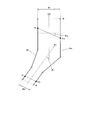
- FIG. 4 is a schematic view showing an example of a rail pattern of an oblique stretching machine.
- the feeding direction D1 of the long original film is different from the winding direction D2 of the stretched film after stretching, and the feeding angle ⁇ i is formed.
- the feeding angle ⁇ i can be arbitrarily set to a desired angle within a range of more than 0 ° and less than 90 °.
- the both ends of the long laminated film described above are gripped with the left and right grippers (tenters) and run.
- the left and right gripping tools Ci and Co facing the direction substantially orthogonal to the film transport direction (feeding direction D1) at the entrance of the oblique stretching machine (position A in the drawing) are: Each travels on asymmetrical rails Ri and Ro.
- the left and right gripping tools release the gripped film at the position at the end of stretching (position B in the figure).
- the gripping tool Ci traveling on the Ri side travels on the Ro side.
- the gripping tool Co Proceed with respect to the gripping tool Co. That is, at the entrance of the oblique stretching machine (the gripping start position by the film gripping tool) A, the straight line connecting the gripping tools Ci and Co is substantially perpendicular to the film feeding direction D1.
- the straight line connecting the grippers Ci and Co is inclined by an angle ⁇ L with respect to a direction substantially perpendicular to the film winding direction D2. .
- the laminated film is obliquely stretched in the direction of ⁇ L.
- substantially vertical indicates a range of 90 ⁇ 1 °.
- a section that travels with a constant interval between the gripping tools gripping both ends is a “preheating zone”. Further, the interval between the gripping tools gripping both ends is opened, and a section until the predetermined interval is reached becomes an “extension zone”. Furthermore, in a period in which the interval between the gripping tools after the stretching zone becomes constant again, a section in which the gripping tools at both ends travel while being parallel to each other is a “heat fixing zone or heat fixing / cooling zone”.
- the temperature of the preheating zone and the stretching zone is preferably in the range of Tg to Tg + 30 ° C. when the glass transition temperature of the cellulose ester is Tg; the temperature of the heat setting zone or heat setting / cooling zone is Tg-30 It is preferable to set within the range of ⁇ Tg ° C.
- the length of the preheating zone, stretching zone, and heat setting zone can be selected as appropriate.
- the length of the preheating zone can usually be in the range of 100-150% with respect to the length of the drawing zone; the length of the heat setting zone should normally be in the range of 50-100% Can do.
- FIG. 5 is a schematic diagram showing an example of an oblique stretching machine having a different rail pattern.
- An oblique stretching machine 20 shown in FIGS. 5A to 5C includes a film feeding device 21, a transport direction changing device 23, and a winding device 25.
- the obtained long optical film is wound up in the long direction (perpendicular to the width direction) of the film using a winder.
- the winding method is not particularly limited, and may be a constant torque method, a constant tension method, a taper tension method, or the like.
- the winding tension at the time of winding the optical film can be about 50 to 170N.
- Circularly polarizing plate contains a polarizer and the optical film of this invention arrange
- a polarizer is an element that allows only light of a polarization plane in a certain direction to pass through.
- a typical example of the polarizer is a polyvinyl alcohol-based polarizing film, and there are one in which a polyvinyl alcohol-based film is dyed with iodine and one in which a dichroic dye is dyed.
- the polarizer can be obtained by uniaxially stretching a polyvinyl alcohol film and then dyeing; or after dying a polyvinyl alcohol film and uniaxially stretching, and preferably by further performing a durability treatment with a boron compound.
- the film thickness of the polarizer is preferably in the range of 5 to 30 ⁇ m, and more preferably in the range of 5 to 20 ⁇ m.
- polyvinyl alcohol film examples include an ethylene unit content of 1 to 4 mol%, a degree of polymerization of 2000 to 4000, a degree of saponification of 99.0 to 99 described in JP2003-248123A, JP2003-342322A, and the like. 99 mol% ethylene-modified polyvinyl alcohol is preferably used.
- the optical film of the present invention is disposed on one surface of the polarizer.
- the in-plane slow axis of the optical film of the present invention is preferably 40 to 50 °; more preferably 45 ⁇ 2 ° with respect to the absorption axis of the polarizer.
- a protective film is further disposed on the other surface of the polarizer.
- the protective film include commercially available cellulose ester films such as Konica Minoltak KC8UX, KC5UX, KC4UX, KC8UCR3, KC4SR, KC4BR, KC4CR, KC4DR, KC4FR, KC4KR, KC8UY, KC6UY, KC, HA, KC2UA, KC4UA, KC6UAKC, 2UAH, KC4UAH, KC6UAH (above Konica Minolta Advanced Layer Co., Ltd.); FUJIFILM Corporation).
- the circularly polarizing plate of the present invention can be obtained through a step of bonding a polarizer and the optical film of the present invention through an adhesive.
- the optical film of the present invention has an in-plane slow axis in an oblique direction with respect to the width direction (or longitudinal direction) of the film. Therefore, it is possible to easily manufacture a circularly polarizing plate of a polarizer simply by laminating with a roll-to-roll so that the longitudinal direction of the polarizer having the absorption axis in the longitudinal direction of the film and the longitudinal direction of the optical film overlap. it can.
- the adhesive used for bonding is an aqueous adhesive such as a fully saponified polyvinyl alcohol adhesive or an active energy ray-curable adhesive, and is preferably an aqueous adhesive.
- the surface layer of the optical film of the present invention contains the above-mentioned cellulose acetate B as a main component, it is difficult to be destroyed by the saponification treatment that is performed before bonding with a polarizer using an aqueous adhesive. Therefore, the optical film of the present invention can be in good contact with the polarizer via the aqueous adhesive.
- the active energy ray-curable adhesive further includes an ultraviolet light sensitizer.
- the curable compound contained in the active energy ray-curable adhesive is a cationic polymerizable compound or a radical polymerizable compound, and a cationic polymerizable compound (for example, an epoxy compound) is preferable from the viewpoint of improving adhesiveness.
- the active energy ray-curable adhesive preferably further contains a photosensitizer that exhibits maximum absorption in light having a wavelength longer than 380 nm.
- the composition of the active energy ray-curable adhesive is described in, for example, JP-A-2011-28234.
- Organic EL Display Device has an organic EL element and the circularly polarizing plate of the present invention disposed on the surface on the viewing side.
- FIG. 6 is a schematic diagram illustrating an example of a basic configuration of an organic EL display device.
- the organic EL display device 30 includes an organic EL element 50 and a circularly polarizing plate 70 of the present invention disposed on the surface on the viewing side.
- the organic EL element 50 may have a substrate 51, a metal electrode 53, a TFT 55, an organic light emitting layer 57, a transparent electrode (ITO or the like) 59, an insulating layer 61, a sealing layer 63, and a film 65 (optional) in this order.
- the substrate 51 can be a glass substrate or a plastic film such as polyimide.
- the substrate 51 is preferably a flexible glass film or resin film.
- the metal electrode 53 preferably functions as a cathode and is made of a metal material having high light reflectivity.
- the metal material include Mg, MgAg, MgIn, Al, LiAl, and the like.
- the organic light emitting layer 57 may be a laminate of various organic thin films, for example, a hole injection layer made of a triphenylamine derivative / a light emitting layer laminate made of a fluorescent organic solid such as anthracene; A light emitting layer made of a fluorescent organic solid / a laminate of an electron injection layer made of a perylene derivative or the like; a laminate of the hole injection layer / the light emitting layer / the electron injection layer, or the like.
- the thickness of the organic light emitting layer 57 may be about 10 nm. For this reason, the organic light emitting layer 57 also transmits light almost completely like the transparent electrode 59.
- the transparent electrode 59 is an anode and is made of a transparent conductor such as indium tin oxide (ITO) in order to extract light emitted from the organic light emitting layer 57.
- ITO indium tin oxide
- the film 65 may be any material that can transmit light (transparent), and may be a glass substrate, a plastic film, a thin film, or the like. Especially, when the organic EL display apparatus 30 is a flexible type, it is preferable that the film 65 is a flexible glass film or resin film.
- the organic EL element 50 injects holes and electrons into the organic light emitting layer 57 by applying a voltage between the transparent electrode 59 and the metal electrode 53, and recombines these holes and electrons. Emits light.
- the circularly polarizing plate 70 includes a polarizer 71, an optical film 73 of the present invention disposed on the surface of the polarizer 71 on the organic EL element 50 side, and a protective film 75 disposed on the surface of the polarizer 71 on the viewing side.
- the optical film 73 of the present invention has the above-described base material layer 73-1 and surface layers 73-3 and 73-3 'disposed on both surfaces thereof.
- FIG. 7 is a schematic diagram for explaining the antireflection function by the circularly polarizing plate 70.
- the same members as those in FIG. First when light (including a1 and b1) is incident from the outside in parallel to the normal line of the display screen of the organic EL display device, only linearly polarized light (b1) parallel to the transmission axis direction of the polarizer (LP) 71 is obtained. Passes through a polarizer (LP) 71. The other linearly polarized light (a1) that is not parallel to the transmission axis direction of the polarizer (LP) 71 is absorbed by the polarizer (LP) 71.
- the linearly polarized light component (b2) that has passed through the polarizer (LP) 71 is converted into circularly polarized light (c2) by passing through the optical film 73.
- the circularly polarized light (c2) passes through the film 65, the sealing layer 63, the insulating layer 61, the transparent electrode 59, the organic light emitting layer 57, and the TFT 55, is reflected by the metal electrode 53 (see FIG. 6), and is reversely circularly polarized light. (C3).
- the reversely circularly polarized light (c3) passes through the TFT 55, the organic light emitting layer 57, the transparent electrode 59, the insulating layer 61, the sealing layer 63, and the film 65, and further passes through the optical film 73, whereby the polarizer (LP). 71 is converted into linearly polarized light (b3) in a direction orthogonal to the transmission axis direction of 71. This linearly polarized light (b3) cannot be passed through the polarizer (LP) 71 and is absorbed.
- the optical film 73 of the present invention is stretched obliquely at a high magnification because the difference in tensile elastic modulus between the base material layer 73-1 and the surface layer 73-3 disposed on both surfaces thereof is small (see FIG. 6). Therefore, there is little residual distortion. Therefore, the generation of wrinkles in an oblique direction as shown in FIG. 1 when the organic EL display device 30 including the optical film 73 of the present invention is folded can be suppressed.
- Optical Film Material 1 Cellulose Ester
- Dac represents the acetyl group substitution degree
- Dpr represents the propionyl group substitution degree
- Dall represents the total substitution degree.
- Example 1 Preparation of dope The following components were put into a sealed container and completely dissolved while heating and stirring. The obtained solution was used as Azumi filter paper No. manufactured by Azumi Filter Paper Co., Ltd. After filtration at 24, the mixture was further filtered with Finemet NF manufactured by Nippon Seisen Co., Ltd. to obtain a dope solution for the base material layer.
- composition of dope for substrate layer CAP1: 100 parts by weight PE-A: 10 parts by weight Wavelength dispersion adjusting agent Compound (24): 4.0 parts by weight Matting agent dispersion (AEROSIL R972, manufactured by Nippon Aerosil Co., Ltd., secondary average particle size of 1.0 ⁇ m or less) ): 0.13 parts by weight of solid content with respect to 100 parts by weight of cellulose ester Dichloromethane: 406 parts by weight Methanol: 61 parts by weight Butanol: 2 parts by weight
- the obtained film was dried with hot air at 140 ° C. until the residual solvent amount was less than 1.0%, and then the film was wound up. Next, the wound film was unwound and stretched in the direction of 45 ° with respect to the width direction of the film at a stretch ratio of 2.0 times at 180 ° C. Thereby, an optical film 101 having a three-layer structure of surface layer / base material layer / surface layer was obtained.
- Examples 2 to 6, Comparative Examples 3 to 4 The optical films 104 to 100 were formed in the same manner as in Example 1 except that the ratio of the amount of plasticizer contained in the surface layer to the amount of plasticizer contained in the base material layer (plasticizer content ratio) was changed as shown in Table 4. 110 was obtained.
- Example 7 An optical film 111 was obtained in the same manner as in Example 1 except that the base material layer did not contain a wavelength dispersing agent.
- Example 8 to 10 Comparative Examples 5 to 7
- Optical films 112 to 117 were obtained in the same manner as in Example 1 except that the type of cellulose ester contained in the base material layer or the surface layer was changed as shown in Table 4.
- Optical films 118 to 121 were obtained in the same manner as in Example 1 except that the type of plasticizer contained in the base material layer or the surface layer was changed as shown in Table 4.
- Example 15 to 16 Optical films 122 to 123 were obtained in the same manner as in Example 1 except that the thickness ratio and total thickness of each layer were changed as shown in Table 4.
- Optical films 131 to 133 were obtained in the same manner as in Example 1 except that the amounts of the plasticizer contained in the surface layer and the base material layer were changed as shown in Table 5.
- the in-plane elastic modulus ratio of the obtained optical film, the elastic modulus difference between the surface layer and the base material layer, cracks, flatness and retardation were evaluated by the following methods.
- the sample film was cut into a size of 1 cm ⁇ 10 cm parallel to the slow axis direction (+ 45 ° direction with respect to the TD direction) of the optical film to obtain a sample film S1.
- a sample film S2 was cut out to a size of 1 cm ⁇ 10 cm parallel to a direction perpendicular to the slow axis direction of the optical film ( ⁇ 45 ° direction with respect to the TD direction).
- the sample films S1 and S2 were conditioned for 24 hours in an environment of 25 ° C. and 55% RH.
- the sample film S1 after humidity control was set to 50 mm between the chucks using Tensilon RTC-1225A manufactured by Orientec Co., Ltd., and the longitudinal direction (slow axis direction) of the sample film
- the tensile elastic modulus X in the slow axis direction was measured.
- the sample film S2 was pulled in the longitudinal direction (direction perpendicular to the slow axis direction), and the tensile elastic modulus Y in the direction perpendicular to the slow axis direction was measured.
- the tensile modulus was measured at 25 ° C. and 55% RH.
- Retardation Ro and Rth were measured by the following methods. 1) The optical film was conditioned at 23 ° C. and 55% RH. The average refractive index of the optical film after humidity control was measured with an Abbe refractometer. 2) Ro was measured with an AxoScan manufactured by Axometric, when light having a measurement wavelength of 550 nm was incident on the optical film after humidity control in parallel with the normal line of the film surface.
- nx, ny and nz were calculated by AxoScan manufactured by Axometric, and Rth at a measurement wavelength of 590 nm was calculated. .
- the retardation was measured under the conditions of 23 ° C. and 55% RH.
- the optical films of Examples 1 to 23 do not cause cracks in the surface layer even when stretched at a high magnification in an oblique direction; the optical films of Comparative Examples 2 to 5 It turns out that a crack arises.
- the reason why no cracks occurred in the optical films of Examples 1 to 24 is considered that the tensile elastic modulus of the surface layer was lowered by relatively increasing the amount of plasticizer contained in the surface layer.
- the reason why cracks occurred in the optical film of Comparative Example 2 is considered that the stretch ratio in the oblique direction was too high. It is considered that the cracks occurred in the optical films of Comparative Examples 3 and 4 because the amount of the plasticizer in the surface layer was small.
- the optical film of Comparative Example 5 is considered to have cracks due to the high tensile elastic modulus of the film. It is considered that the optical films of Comparative Examples 6 and 7 were slightly inferior in compatibility between the cellulose ester and the plasticizer in the surface layer than the optical film of Comparative Example 5, and thus the planarity of the film was lowered.
- the retardation Ro in the in-plane direction at a wavelength of 550 nm of the optical film of Example 1 was 135 nm; the retardation Rth in the thickness direction was 70 nm.
- Ro of the optical films of Examples 2 to 24 was 120 to 140 nm, and Rth was 65 to 100 nm.
- the difference between the tensile elastic modulus of the film constituting the surface layer and the tensile elastic modulus of the film constituting the base material layer is 0.2 GPa in Example 1; ⁇ 0.4 GPa; in Comparative Example 3, it was 1.3 GPa.
- Example 25 Production of Polarizer A long polyvinyl alcohol film having a thickness of 120 ⁇ m was uniaxially stretched under conditions of a stretching temperature of 110 ° C. and a stretching ratio of 5 times. The obtained film was immersed in an aqueous solution consisting of 0.075 g of iodine, 5 g of potassium iodide and 100 g of water for 60 seconds, and then immersed in an aqueous solution of 68 ° C. consisting of 6 g of potassium iodide, 7.5 g of boric acid and 100 g of water. . The obtained film was washed with water and dried to obtain a long polarizer having a thickness of 20 ⁇ m.
- Circular Polarizing Plate 201 The surface of the produced optical film 101 bonded to the polarizer was subjected to alkali saponification treatment. Then, the optical film 101 was bonded to one surface of the long polarizer through a 5% aqueous solution of a completely saponified polyvinyl alcohol as an adhesive. The bonding was performed by aligning the longitudinal direction of the polarizer and the longitudinal direction of the optical film so that the transmission axis of the polarizer and the slow axis of the optical film 101 form 45 °.
- Konica Minolta Tack Film KC4UA (manufactured by Konica Minolta Opto Co., Ltd.) was prepared, and the bonding surface with the polarizer was subjected to alkali saponification treatment. Then, KC4UA (manufactured by Konica Minolta Opto Co., Ltd.) was bonded to the other surface of the polarizer through a completely saponified polyvinyl alcohol 5% aqueous solution in the same manner as described above. Thereby, a circularly polarizing plate 201 was obtained.
- a metal electrode made of chromium having a thickness of 80 nm was formed on a PET film by sputtering; a thin film of ITO having a thickness of 40 nm was formed on the metal electrode as an anode.
- a hole transport layer made of poly (3,4-ethylenedioxythiophene) -polystyrene sulfonate (PEDOT: PSS) having a thickness of 80 nm is formed on the anode by sputtering;
- RGB light emitting layers red light emitting layer, green light emitting layer, and blue light emitting layer
- the thickness of the light emitting layer was 100 nm for each color.
- the red light-emitting layer contains tris (8-hydroxyquinolinate) aluminum (Alq 3 ) as a host and a light-emitting compound [4- (dicyanomethylene) -2-methyl-6 (p-dimethylaminostyryl) -4H-pyran] (DCM).
- the green light-emitting layer is formed by co-evaporating Alq 3 and the luminescent compound coumarin 6 (mass ratio 99: 1) as a host;
- the layer was formed by co-evaporating BAlq and a luminescent compound Perylene as a host (mass ratio 90:10).
- a thin film having a thickness of 4 nm made of calcium is formed as a first cathode having a low work function so that electrons can be efficiently injected by a vacuum deposition method;
- a thin film made of aluminum having a thickness of 2 nm was formed as a second cathode to obtain an organic light emitting layer.
- the aluminum used as the second cathode has a role of preventing the first cathode calcium from being chemically altered when a transparent electrode is formed thereon by sputtering.
- a transparent conductive film made of ITO and having a thickness of 80 nm (the first cathode, the second cathode, and the transparent conductive film were combined to form a transparent electrode layer) was formed on the second cathode by sputtering. Furthermore, a thin film having a thickness of 200 nm made of silicon nitride was formed on the transparent conductive film by a CVD method to obtain an insulating film (transparent substrate). Thereby, an organic EL element was obtained.
- a circularly polarizing plate 201 was bonded to the obtained insulating film (transparent substrate) of the organic EL element with an adhesive to obtain an organic EL display device 301.
- the circularly polarizing plate 201 was bonded so that the optical film 101 was on the insulating film side of the organic EL element.
- Circularly polarizing plates 202 to 233 and organic EL display devices 302 to 333 were obtained in the same manner as in Example 25 except that the optical film 101 was changed as shown in Table 6.
- the wrinkles and display performance during bending of the obtained organic EL display device were evaluated by the following methods.
- Table 6 shows the evaluation results of the organic EL display devices of Examples 25 to 48 and Comparative Examples 10 to 18.
- the organic EL display devices of Examples 25 to 48 have almost no wrinkles in the oblique direction when bent, and the display performance is good; the organic EL displays of Comparative Examples 11 to 18 It can be seen that the display device is wrinkled in an oblique direction at least when bent, and the display performance is low.
- Comparative Example 10 it is considered that the display performance of the organic EL display device is low because the stretch ratio of the optical film 102 is low and the desired retardation is not obtained.
- Comparative Examples 11 to 13 it can be seen that wrinkles in an oblique direction at the time of bending occur because the difference in tensile elastic modulus of each layer of the optical film is large as described above.
- the display devices of Comparative Examples 14 to 16 have low display performance. This is because the main component of the surface layer of the optical film used in Comparative Example 15 is CAP; the main component of the surface layer of the optical film used in Comparative Example 16 is DAC. This is probably because the surface was destroyed.
Landscapes
- Polarising Elements (AREA)
- Electroluminescent Light Sources (AREA)
- Laminated Bodies (AREA)
Abstract
本発明の目的は、斜め延伸によって生じるクラックが少なく、有機EL表示装置を折り曲げた時に生じる斜め方向のシワを抑制できる光学フィルムを提供することである。本発明の光学フィルムは、セルロースアセテートプロピオネートまたはアセチル基の置換度が2.0以上2.6以下のセルロースアセテートと可塑剤とを含有する基材層と、前記基材層の両面に配置され、アセチル基の置換度が2.6超3.0以下のセルロースアセテートと可塑剤とを含有する表層とを含む、有機EL表示装置用の光学フィルムであって、前記光学フィルムの面内の遅相軸方向が、フィルムの幅方向に対して斜め方向であり、前記遅相軸方向の引張弾性率Xの、前記遅相軸方向と直交する方向の引張弾性率Yに対する比X/Yが1.5以上5.0以下であり、前記表層に含まれる可塑剤の量が、前記基材層に含まれる可塑剤の量の1.2倍以上5.5倍以下である。
Description
本発明は、光学フィルムとその製造方法、円偏光板および有機EL表示装置に関する。
有機EL表示装置(例えばトップエミッション型の有機EL表示装置)は、通常、金属電極(陰極)、有機発光層、透明電極(陽極)および透明基板がこの順に積層された有機EL素子を含む。
このような有機EL表示装置では、発光層で発光した光だけでなく、透明基板を介して入射する外光も、金属電極表面で鏡面反射し、出射光として取り出される。そのため、室内照明などの外光が映り込み、視認性が低下するという問題があった。
このような外光の映り込みによる視認性の低下を抑制するために、有機EL素子の視認側に円偏光板を設けることが検討されている。円偏光板を構成するλ/4位相差フィルムとしては、例えばセルローストリアセテート(TAC)の積層フィルムなどが提案されている(例えば特許文献1)。
その他、液晶表示装置の位相差フィルムなどに用いられる積層フィルムとして、TAC/セルロースアセテートプロピオネート(CAP)/TACの積層フィルム(例えば特許文献2)、CAPの積層フィルム(例えば特許文献3)、およびTACの積層フィルム(例えば特許文献4)などが提案されている。
ところで、λ/4位相差フィルムは比較的大きな位相差を有することから、その主成分は、位相差発現性が高いセルロースジアセテート(DAC)や、高倍率に延伸しやすいセルロースアセテートプロピオネート(CAP)であることが好ましいと考えられる。
一方で、本発明者らは、CAPやDACを主成分とするフィルムは、いずれもアルカリ水溶液による鹸化により、TACを主成分とするフィルムよりも、フィルム表面が破壊されやすいことを、鹸化後のフィルム表面の観察により見出した。フィルム表面の破壊とは、具体的には、CAPやDACを主成分とするフィルムは、TACを主成分とするフィルムよりも水酸基を比較的多く含むことから、アルカリ水溶液(鹸化液)がフィルム内部まで浸透しやすく、セルロースエステルが過剰に加水分解されることに起因すると考えられる。そのため、CAPやDACを主成分とするフィルムは、TACを主成分とするフィルムよりも、鹸化後のフィルムの偏光子との接着性が劣ることが分かった。
これに対して、CAPやDACを主成分とする基材層と、TACを主成分とする表層とを有する積層フィルムは、TACを主成分とする表層が、鹸化による破壊を受けにくいため、偏光子との密着性を改善できると考えられる。
しかしながら、上記積層フィルムを斜め方向に高倍率で延伸すると、表層にクラックが生じることがあった。さらに、上記積層フィルムを含むフレキシブルタイプの有機EL表示装置を折り曲げた時に、折り曲げ部分の積層フィルムに斜め方向のシワが生じることがあった。斜め方向のシワは、表示性能を低下させる原因となりやすい。
本発明は、上記事情に鑑みてなされたものであり、斜め延伸によって生じるクラックが少なく、平面性がよく、有機EL表示装置を折り曲げた時に生じる斜め方向のシワを抑制できる光学フィルムを提供することを目的とする。
[1] セルロースアセテートプロピオネートまたはアセチル基の置換度が2.0以上2.6以下のセルロースアセテートと可塑剤とを含有する基材層と、前記基材層の両面に配置され、アセチル基の置換度が2.6超3.0以下のセルロースアセテートと可塑剤とを含有する表層とを含む、有機EL表示装置用の光学フィルムであって、前記光学フィルムの面内の遅相軸方向が、フィルムの幅方向に対して斜め方向であり、前記遅相軸方向の引張弾性率Xの、前記遅相軸方向と直交する方向の引張弾性率Yに対する比X/Yが1.5以上5.0以下であり、前記表層に含まれる可塑剤の量の前記基材層に含まれる可塑剤の量に対する質量比が、1.2倍以上5.5倍以下である、光学フィルム。
[2] 前記光学フィルムの面内の遅相軸方向が、フィルムの幅方向に対して40~50°の範囲である、[1]に記載の光学フィルム。
[3] 前記基材層が、波長分散調整剤をさらに含有する、[1]または[2]に記載の光学フィルム。
[4] 前記表層に含まれる可塑剤の量が、前記表層に含まれる前記アセチル基の置換度が2.6超3.0以下のセルロースアセテートに対して15~50質量%である、[1]~[3]のいずれかに記載の光学フィルム。
[5] 前記基材層に含まれるセルロースアセテートプロピオネートまたはアセチル基の置換度が2.0以上2.6以下のセルロースアセテートの重量平均分子量Mwが15万~30万であり、かつ数平均分子量Mnが5万~20万である、[1]~[4]のいずれかに記載の光学フィルム。
[6] 前記表層に含まれる可塑剤が、ジオールとジカルボン酸とを重縮合反応させて得られるポリエステル化合物である、[1]~[5]のいずれかに記載の光学フィルム。
[7] 前記ポリエステル化合物の重量平均分子量が700~2000である、[6]に記載の光学フィルム。
[8] 前記ポリエステル化合物の分子末端は、水酸基であるか、アセチル基で封止されている、[6]または[7]に記載の光学フィルム。
[9] 前記ポリエステル化合物を構成する前記ジカルボン酸が、芳香族ジカルボン酸と、脂肪族ジカルボン酸とを含有する、[6]~[8]のいずれかに記載の光学フィルム。
[10] 前記光学フィルムの、式(I)で定義され、波長550nmにおける面内方向のレターデーションRoが120~180nmの範囲内であり、式(II)で定義され、波長550nmにおける厚み方向のレターデーションRthが50~100nmである、[1]~[9]のいずれかに記載の光学フィルム。
式(I) Ro=(nx-ny)×d
式(II) Rth={(nx+ny)/2-nz}×d
(nx:フィルム面内の遅相軸方向xの屈折率、ny:フィルム面内において、遅相軸方向xに対して直交する方向yの屈折率、nz:フィルムの厚み方向zの屈折率、d:フィルムの厚み(nm))
[11] [1]~[10]のいずれかに記載の光学フィルムを含む、円偏光板。
[12] [1]~[10]のいずれかに記載の光学フィルムを含む、有機EL表示装置。
[2] 前記光学フィルムの面内の遅相軸方向が、フィルムの幅方向に対して40~50°の範囲である、[1]に記載の光学フィルム。
[3] 前記基材層が、波長分散調整剤をさらに含有する、[1]または[2]に記載の光学フィルム。
[4] 前記表層に含まれる可塑剤の量が、前記表層に含まれる前記アセチル基の置換度が2.6超3.0以下のセルロースアセテートに対して15~50質量%である、[1]~[3]のいずれかに記載の光学フィルム。
[5] 前記基材層に含まれるセルロースアセテートプロピオネートまたはアセチル基の置換度が2.0以上2.6以下のセルロースアセテートの重量平均分子量Mwが15万~30万であり、かつ数平均分子量Mnが5万~20万である、[1]~[4]のいずれかに記載の光学フィルム。
[6] 前記表層に含まれる可塑剤が、ジオールとジカルボン酸とを重縮合反応させて得られるポリエステル化合物である、[1]~[5]のいずれかに記載の光学フィルム。
[7] 前記ポリエステル化合物の重量平均分子量が700~2000である、[6]に記載の光学フィルム。
[8] 前記ポリエステル化合物の分子末端は、水酸基であるか、アセチル基で封止されている、[6]または[7]に記載の光学フィルム。
[9] 前記ポリエステル化合物を構成する前記ジカルボン酸が、芳香族ジカルボン酸と、脂肪族ジカルボン酸とを含有する、[6]~[8]のいずれかに記載の光学フィルム。
[10] 前記光学フィルムの、式(I)で定義され、波長550nmにおける面内方向のレターデーションRoが120~180nmの範囲内であり、式(II)で定義され、波長550nmにおける厚み方向のレターデーションRthが50~100nmである、[1]~[9]のいずれかに記載の光学フィルム。
式(I) Ro=(nx-ny)×d
式(II) Rth={(nx+ny)/2-nz}×d
(nx:フィルム面内の遅相軸方向xの屈折率、ny:フィルム面内において、遅相軸方向xに対して直交する方向yの屈折率、nz:フィルムの厚み方向zの屈折率、d:フィルムの厚み(nm))
[11] [1]~[10]のいずれかに記載の光学フィルムを含む、円偏光板。
[12] [1]~[10]のいずれかに記載の光学フィルムを含む、有機EL表示装置。
[13] [1]~[10]のいずれかに記載の光学フィルムの製造方法であって、セルロースアセテートプロピオネートまたはアセチル基の置換度が2.0以上2.6以下のセルロースアセテートと可塑剤とを含有する第一の層と、前記第一の層の両面に配置され、アセチル基の置換度が2.6超3.0以下のセルロースアセテートと可塑剤とを含有する第二の層とを含む積層フィルムを得る工程と、前記積層フィルムを、少なくとも前記積層フィルムの幅方向に対して斜め方向に1.5倍以上3.0倍以下の倍率で延伸して、光学フィルムを得る工程とを含む、光学フィルムの製造方法。
[14] 前記積層フィルムを得る工程は、セルロースアセテートプロピオネートまたはアセチル基の置換度が2.0以上2.6以下のセルロースアセテート、可塑剤および有機溶媒を含有する第一の層用ドープと、アセチル基の置換度が2.6超3.0以下のセルロースアセテート、可塑剤および有機溶媒を含有する第二の層用ドープとを得る工程と;前記第一の層用ドープと前記第二の層用ドープとを、流延支持体上に同時または逐次に積層しながら流延する工程と;前記積層された前記第一の層用ドープと前記第二の層用ドープに含まれる有機溶媒を除去して、積層フィルムを得る工程とを含む、[13]に記載の光学フィルムの製造方法。
[15] 前記積層フィルムの延伸は、フィルムの幅方向に対して40~50°の方向に行う、[13]または[14]に記載の光学フィルムの製造方法。
[14] 前記積層フィルムを得る工程は、セルロースアセテートプロピオネートまたはアセチル基の置換度が2.0以上2.6以下のセルロースアセテート、可塑剤および有機溶媒を含有する第一の層用ドープと、アセチル基の置換度が2.6超3.0以下のセルロースアセテート、可塑剤および有機溶媒を含有する第二の層用ドープとを得る工程と;前記第一の層用ドープと前記第二の層用ドープとを、流延支持体上に同時または逐次に積層しながら流延する工程と;前記積層された前記第一の層用ドープと前記第二の層用ドープに含まれる有機溶媒を除去して、積層フィルムを得る工程とを含む、[13]に記載の光学フィルムの製造方法。
[15] 前記積層フィルムの延伸は、フィルムの幅方向に対して40~50°の方向に行う、[13]または[14]に記載の光学フィルムの製造方法。
本発明によれば、斜め延伸によって生じるクラックが少なく、有機EL表示装置を折り曲げた時に生じる斜め方向のシワを抑制できる光学フィルムを提供することができる。
1.光学フィルム
本発明の光学フィルムは、基材層と、その少なくとも一方の面;好ましくは両面に配置される表層とを含む。本発明の光学フィルムは、有機EL表示装置の円偏光板を構成する光学フィルムとして好ましく用いられる。
本発明の光学フィルムは、基材層と、その少なくとも一方の面;好ましくは両面に配置される表層とを含む。本発明の光学フィルムは、有機EL表示装置の円偏光板を構成する光学フィルムとして好ましく用いられる。
基材層について
基材層は、セルロースアセテートプロピオネートA1またはアセチル基の置換度が2.0以上2.6以下のセルロースアセテートA2と、可塑剤とを含む。
基材層は、セルロースアセテートプロピオネートA1またはアセチル基の置換度が2.0以上2.6以下のセルロースアセテートA2と、可塑剤とを含む。
基材層に含まれるセルロースアセテートプロピオネートA1は、アシル基がプロピオニル基とアセチル基とからなるセルロースエステルである。
セルロースアセテートプロピオネートA1のアシル基の総置換度は、2.0以上3.0以下であることが好ましく、2.2以上2.9以下であることがより好ましく、2.4以上2.8以下であることがさらに好ましく、2.4以上2.5以下であることが特に好ましい。アシル基の総置換度が低いと、面内方向のレターデーションRoの発現性は高いが、Roの波長分散特性はフラットになりやすい。一方、アシル基の総置換度が高いと、面内方向のレターデーションRoの発現性は低いが、Roの波長分散特性は逆分散となりやすい。
セルロースアセテートプロピオネートA1のプロピオニル基の置換度は、フィルムの延伸性を一定以上とするためには、0.5以上であることが好ましく、0.8以上であることがより好ましい。一方、フィルムの強度を確保するためには、プロピオニル基の置換度は、1.5以下であることが好ましく、1.0以下であることがより好ましい。
アシル基の総置換度(アセチル基置換度)の測定方法は、ASTM-D817-96に準じて測定することができる。
基材層に含まれるセルロースアセテートA2は、アシル基の全てがアセチル基であり、アシル基の総置換度(アセチル基の置換度)が2.0以上2.6以下のセルロースエステルである。
セルロースアセテートA2のアシル基の総置換度(アセチル基の置換度)は、一定以上の位相差発現性を得るためには、2.2以上2.5以下であることがより好ましい。
セルロースアセテートプロピオネートA1およびセルロースアセテートA2の重量平均分子量Mwは、製膜しやすく、フィルムの機械的強度を得るために、12万~35万であることが好ましく、15万~30万であることが好ましく、18~25万であることがより好ましい。また、セルロースアセテートプロピオネートA1およびセルロースアセテートA2の数平均分子量Mnは、4万~21万であることが好ましく、5万~20万であることが好ましく、6万~10万であることがより好ましい。
セルロースアセテートプロピオネートA1およびセルロースアセテートA2の分子量分布(重量平均分子量Mw/数平均分子量Mn)は、1.0~3.0であることが好ましい。さらに好ましくは2.2以上2.9以下である。
セルロースアセテートプロピオネートA1およびセルロースアセテートA2の重量平均分子量は、ゲルパーミエーションクロマトグラフィー(GPC)により測定することができる。測定条件は以下の通りである。
溶媒:メチレンクロライド
カラム:Shodex K806、K805、K803G(昭和電工(株)製)を3本接続して使用する。
カラム温度:25℃
試料濃度:0.1質量%
検出器:RI Model 504(GLサイエンス社製)
ポンプ:L6000(日立製作所(株)製)
流量:1.0ml/min
校正曲線:標準ポリスチレンSTK standardポリスチレン(東ソー(株)製)Mw=1.0×10⁶~5.0×10²までの13サンプルによる校正曲線を使用する。13サンプルは、ほぼ等間隔に選択することが好ましい。
溶媒:メチレンクロライド
カラム:Shodex K806、K805、K803G(昭和電工(株)製)を3本接続して使用する。
カラム温度:25℃
試料濃度:0.1質量%
検出器:RI Model 504(GLサイエンス社製)
ポンプ:L6000(日立製作所(株)製)
流量:1.0ml/min
校正曲線:標準ポリスチレンSTK standardポリスチレン(東ソー(株)製)Mw=1.0×10⁶~5.0×10²までの13サンプルによる校正曲線を使用する。13サンプルは、ほぼ等間隔に選択することが好ましい。
セルロースアセテートプロピオネートA1は、プロピオニル基を含むため、延伸性が比較的高い。また、セルロースアセテートA2は、アシル基の全てがアセチル基であり、かつ低置換度であるため、延伸による位相差発現性が高い。そのため、セルロースアセテートプロピオネートA1およびセルロースアセテートA2は、いずれも一定以上の位相差を有する有機EL表示装置用の光学フィルムとして好適である。
基材層に含まれる可塑剤は、ポリエステル化合物、糖エステル化合物、エステル化合物(脂肪酸エステル化合物やリン酸エステル化合物などを含む)、多価アルコールエステル化合物、多価カルボン酸エステル化合物(フタル酸エステル化合物を含む)、グリコレート化合物などでありうる。なかでも、セルロースエステルとの相溶性が高いこと、機械的強度を向上させる点から、ポリエステル化合物が好ましい。
ポリエステル化合物は、ジカルボン酸とジオールとの縮合物に由来する繰り返し単位を含む。ポリエステル化合物を構成するジカルボン酸は、脂肪族ジカルボン酸、脂環式ジカルボン酸または芳香族ジカルボン酸でありうる。脂肪族ジカルボン酸の炭素数は、好ましくは4~20であり、より好ましくは4~12である。脂肪族ジカルボン酸の例には、マロン酸、コハク酸、グルタル酸、アジピン酸、ピメリン酸、スベリン酸、アゼライン酸、セバシン酸、ウンデカンジカルボン酸、ドデカンジカルボン酸等が含まれる。
芳香族ジカルボン酸の炭素数は、好ましくは8~20であり、より好ましくは8~12である。芳香族ジカルボン酸の例には、1,2-ベンゼンジカルボン酸(フタル酸)、1,3-ベンゼンジカルボン酸(イソフタル酸)、1,4-ベンゼンジカルボン酸(テレフタル酸)、1,5-ナフタレンジカルボン酸、1,4-キシリデンジカルボン酸等が含まれ、好ましくは1,4-ベンゼンジカルボン酸(テレフタル酸)である。
脂環式ジカルボン酸の炭素数は、好ましくは6~20であり、より好ましくは6~12である。脂環式ジカルボン酸の例には、1,3-シクロブタンジカルボン酸、1,3-シクロペンタンジカルボン酸、1,4-シクロヘキサンジカルボン酸、1,4-シクロヘキサンジ酢酸等が含まれる。
ポリエステル化合物を構成するジカルボン酸は、一種類であっても、二種類以上あってもよい。ポリエステル化合物を構成するジカルボン酸は、セルロースエステルとの相溶性を高めるためには芳香族ジカルボン酸を含むことが好ましく;可とう性を付与するためには、脂肪族ジカルボン酸を含むことが好ましい。フィルムに十分な可とう性を付与し、クラックを抑制しやすくするためには、ポリエステル化合物を構成するジカルボン酸は、芳香族ジカルボン酸と脂肪族ジカルボン酸の両方を含有することが好ましい。芳香族ジカルボン酸と脂肪族ジカルボン酸のモル比は、5/95~95/5の範囲、好ましくは30/70~70/30の範囲としうる。
ポリエステル化合物を構成するジオールは、脂肪族ジオール、アルキルエーテルジオール、脂環式ジオールまたは芳香族ジオールでありうる。脂肪族ジオールの炭素数は、好ましくは2~20であり、より好ましくは2~12であり、さらに好ましくは2~4である。脂肪族ジオールの例には、エチレングリコール、1,2-プロピレングリコール、1,3-プロピレングリコール、1,2-ブタンジオール、1,3-ブタンジオール、1,2-プロパンジオール、2-メチル-1,3-プロパンジオール、1,4-ブタンジオール、1,5-ペンタンジオール、2,2-ジメチル-1,3-プロパンジオール(ネオペンチルグリコール)、2,2-ジエチル-1,3-プロパンジオール(3,3-ジメチロールペンタン)、2-n-ブチル-2-エチル-1,3-プロパンジオール(3,3-ジメチロールヘプタン)、3-メチル-1,5-ペンタンジオール、1,6-ヘキサンジオール、2,2,4-トリメチル-1,3-ペンタンジオール、2-エチル-1,3-ヘキサンジオール、2-メチル-1,8-オクタンジオール、1,9-ノナンジオール、1,10-デカンジオール、および1,12-オクタデカンジオールなどが含まれる。アルキルエーテルジオールの炭素数は、好ましくは4~20であり、より好ましくは4~12である。アルキルエーテルジオールの例には、ポリテトラメチレンエーテルグリコール、ポリエチレンエーテルグリコールおよびポリプロピレンエーテルグリコールなどが含まれる。
脂環式ジオールの炭素数は、好ましくは4~20であり、より好ましくは4~12である。脂環式ジオールの例には、1,4-シクロヘキサンジオール、1,4-シクロヘキサンジメタノールなどが含まれる。
芳香族ジオールの炭素数は、好ましくは6~20であり、より好ましくは6~12である。芳香族ジオールの例には、1,2-ジヒドロキシベンゼン(カテコール)、1,3-ジヒドロキシベンゼン(レゾルシノール)、1,4-ジヒドロキシベンゼン(ヒドロキノン)などが含まれる。
ポリエステル化合物を構成するジオールは、一種類であっても、二種類以上あってもよい。ポリエステル化合物を構成するジオールは、脂肪族ジオールを含むことが好ましい。
ポリエステル化合物の分子末端は、必要に応じてモノカルボン酸またはモノアルコールで封止されていてもよい。
モノカルボン酸は、脂肪族モノカルボン酸、脂環式モノカルボン酸または芳香族モノカルボン酸でありうる。脂肪族モノカルボン酸の炭素数は、好ましくは2~30、より好ましくは2~4でありうる。脂肪族カルボン酸の例には、酢酸、プロピオン酸、ブタン酸、カプリル酸、カプロン酸、デカン酸、ドデカン酸、ステアリン酸、オレイン酸などが含まれる。脂環式モノカルボン酸の例には、シクロヘキシルモノカルボン酸などが含まれる。芳香族モノカルボン酸の例には、安息香酸、パラターシャリブチル安息香酸、オルソトルイル酸、メタトルイル酸、パラトルイル酸、ジメチル安息香酸、エチル安息香酸、ノルマルプロピル安息香酸、アミノ安息香酸、アセトキシ安息香酸、フェニル酢酸、3-フェニルプロピオン酸などが含まれる。
モノアルコールは、脂肪族モノアルコール、脂環式モノアルコールまたは芳香族モノアルコールでありうる。脂肪族モノアルコールの炭素数は1~30であり、好ましくは1~3でありうる。脂肪族モノアルコールの例には、メタノール、エタノール、プロパノール、イソプロパノール、ブタノール、イソブタノール、ペンタノール、イソペンタノール、ヘキサノール、イソヘキサノール、オクタノール、イソオクタノール、2-エチルヘキシルアルコール、ノニルアルコール、イソノニルアルコール、tert-ノニルアルコール、デカノール、ドデカノール、ドデカヘキサノール、ドデカオクタノール、アリルアルコール、オレイルアルコールなどが含まれる。脂環式モノアルコールの例には、シクロヘキシルアルコールなどが含まれる。芳香族モノアルコールの例には、ベンジルアルコール、3-フェニルプロパノールなどが含まれる。
なかでも、セルロースエステルとの親和性を高めるためには、ポリエステル化合物の分子末端が未封止であるか、脂肪族モノカルボン酸(好ましくは酢酸)で封止されていることが好ましく;脂肪族モノカルボン酸(好ましくは酢酸)で封止されていることがより好ましい。
ポリエステル化合物の重量平均分子量は、500~2000であることが好ましく、700~2000であることがより好ましい。重量平均分子量が小さすぎるとブリードアウトが生じる可能性がある。重量平均分子量が大きすぎると、セルロースエステルとの相溶性が低下する可能性がある。
環構造を有するポリエステル化合物の具体例には、以下のものが含まれる。後述の表1において、TPA:テレフタル酸、PA:フタル酸、SA:コハク酸、AA:アジピン酸、SEA:セバシン酸を示す。
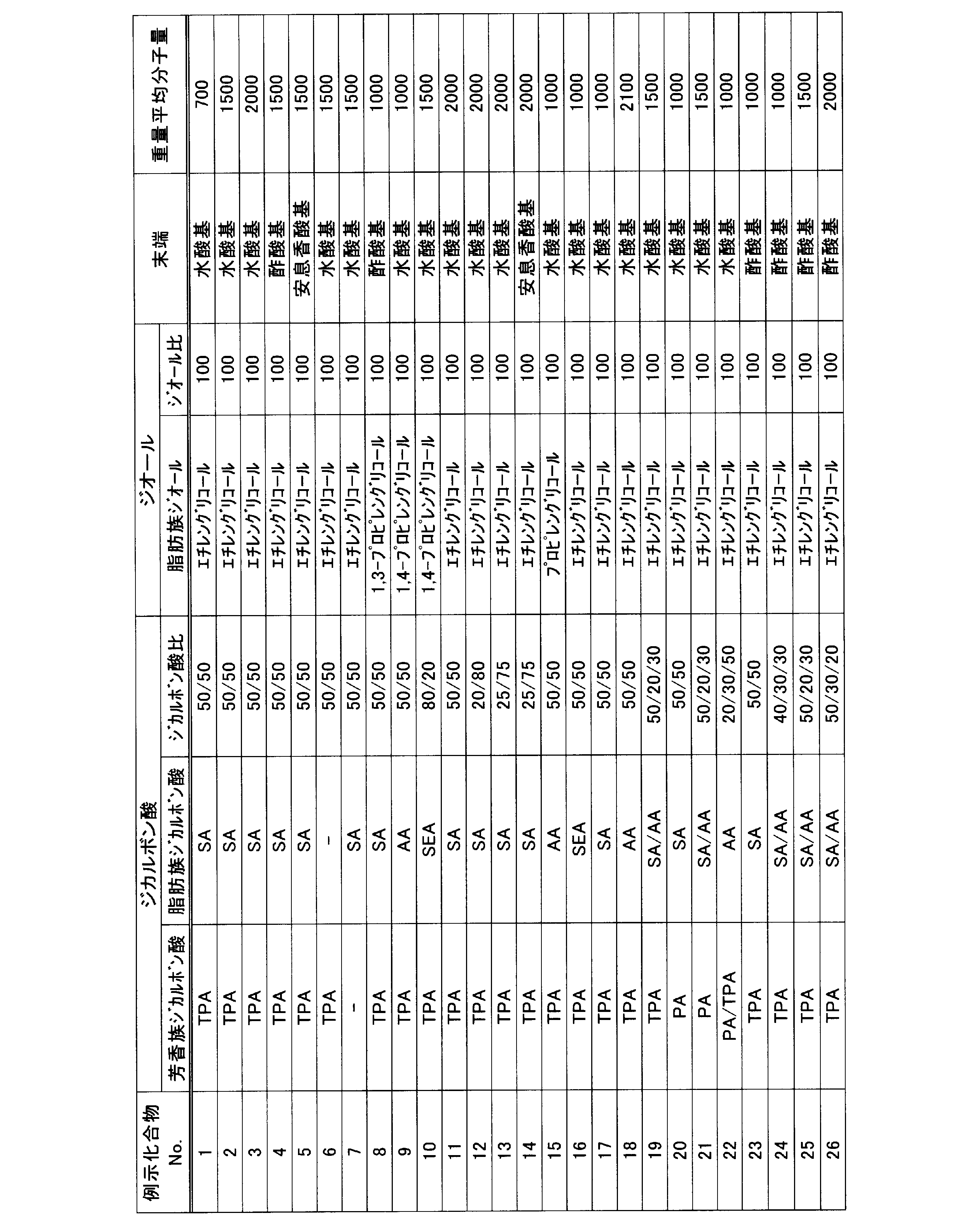
糖エステル化合物は、下記式(FA)で表される化合物であることが好ましい。

式(FA)のR1~R8は、置換もしくは無置換のアルキルカルボニル基、または置換もしくは無置換のアリールカルボニル基を表わす。R1~R8は、互いに同じであっても、異なってもよい。
置換もしくは無置換のアルキルカルボニル基は、炭素原子数2以上の置換もしくは無置換のアルキルカルボニル基であることが好ましい。置換もしくは無置換のアルキルカルボニル基の例には、メチルカルボニル基(アセチル基)、エチルカルボニル基などが含まれる。アルキル基が有する置換基の例には、フェニル基などのアリール基が含まれる。
置換もしくは無置換のアリールカルボニル基は、炭素原子数7以上の置換もしくは無置換のアリールカルボニル基であることが好ましい。アリールカルボニル基の例には、フェニルカルボニル基が含まれる。アリール基が有する置換基の例には、メチル基などのアルキル基が含まれる。
式(FA)で示される化合物の具体例には、以下のものが含まれる。Rは、式(FA)におけるR1~R8を表す。
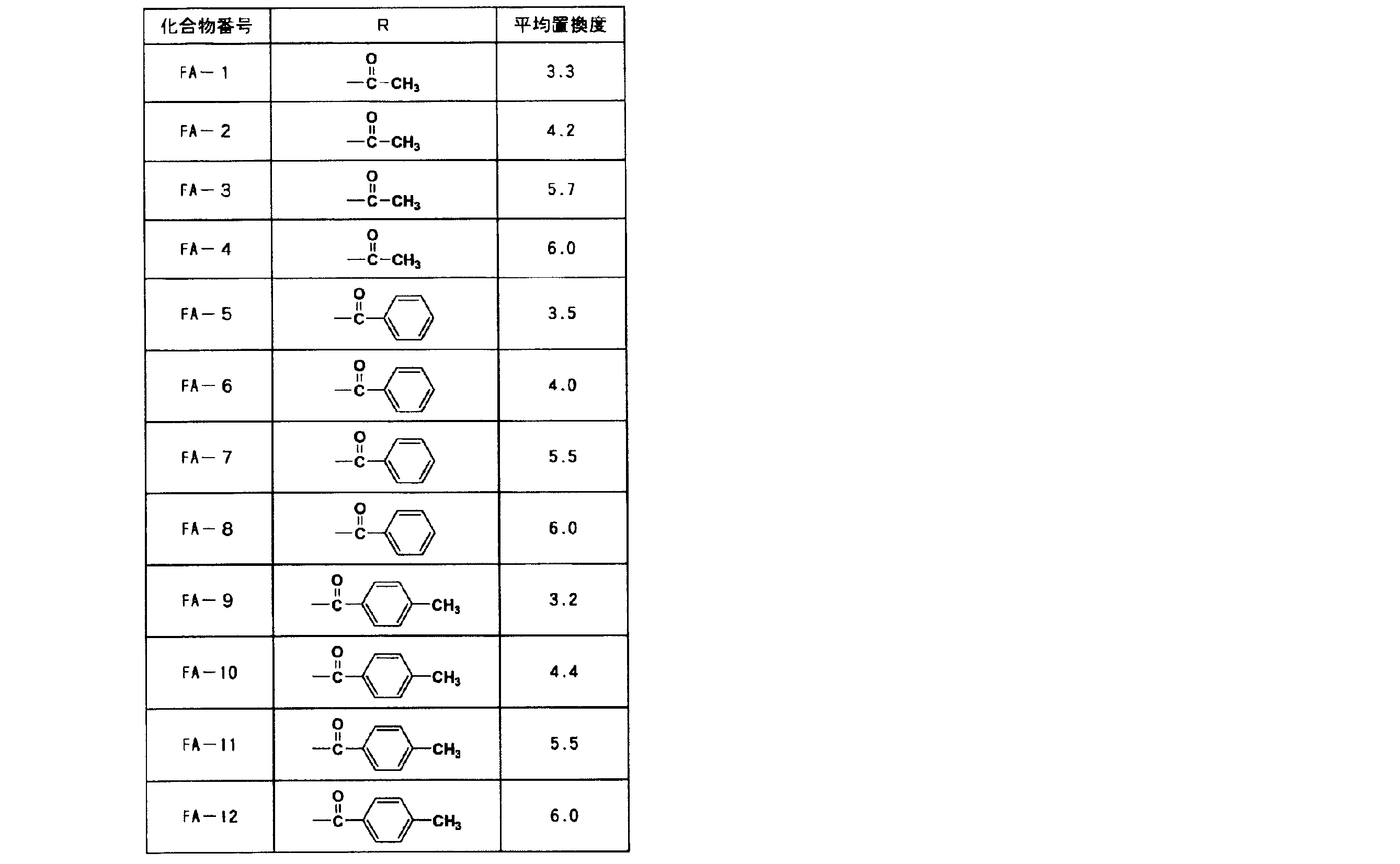
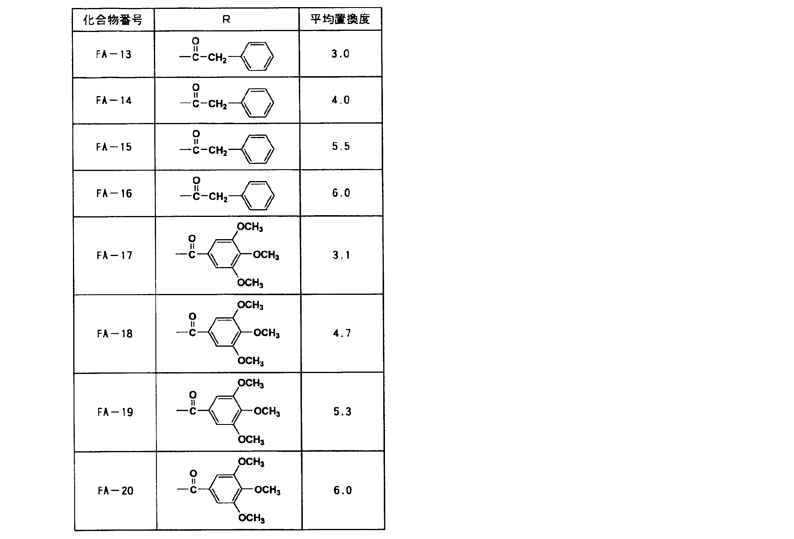
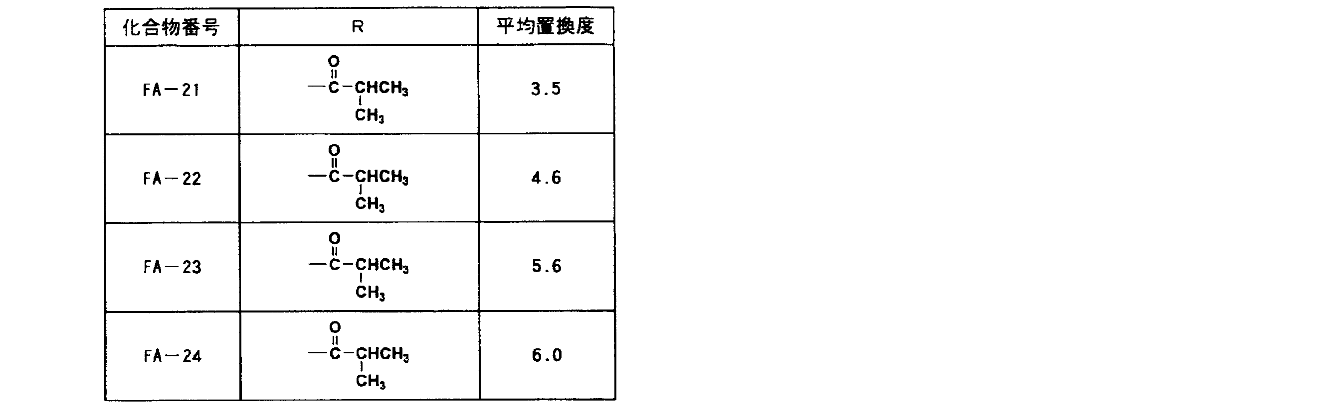
エステル化合物には、脂肪酸エステル化合物、クエン酸エステル化合物やリン酸エステル化合物などが含まれる。脂肪酸エステル化合物の例には、オレイン酸ブチル、リシノール酸メチルアセチル、およびセバシン酸ジブチル等が含まれる。クエン酸エステル化合物の例には、クエン酸アセチルトリメチル、クエン酸アセチルトリエチル、およびクエン酸アセチルトリブチル等が含まれる。リン酸エステル化合物の例には、トリフェニルホスフェート、トリクレジルホスフェート、クレジルジフェニルホスフェート、オクチルジフェニルホスフェート、ビフェニルジフェニルホスフェート、トリオクチルホスフェート、およびトリブチルホスフェート等が含まれ、好ましくはトリフェニルホスフェートである。
これらの可塑剤は、単独で用いても、二種類以上を組み合わせて用いてもよい。
基材層における可塑剤の含有量は、表層における可塑剤の含有量/基材層における可塑剤の含有量との比が後述する範囲となる範囲であればよく、セルロースエステルに対して好ましくは1~45質量%であり、より好ましくは1.5~40質量%である。可塑剤の含有量が1質量%未満であると、可塑性の付与効果が十分でない可能性がある。また、フィルムの透湿性を低下させる観点からは、可塑剤の含有量は20質量%以上であることが好ましい。一方、可塑剤の含有量が45質量%超であると、光学フィルムから可塑剤が染み出す可能性がある。
基材層は、必要に応じて波長分散剤、紫外線吸収剤、マット剤、レターデーション調整剤、劣化防止剤などをさらに含有してもよい。
基材層に含まれる波長分散剤は、下記一般式(A)で表される化合物であることが好ましい。

一般式(A)において、L1およびL2は、それぞれ独立に単結合または2価の連結基を示す。R1、R2およびR3は、それぞれ独立に置換基を示す。nは、0から2までの整数を示す。WaおよびWbは、それぞれ水素原子または置換基を示す。WaとWbが、互いに結合して環を形成してもよいし;WaとWbの少なくとも一つが環構造を有してもよいし;WaとWbの少なくとも一つがアルケニル基またはアルキニル基であってもよい。
WaおよびWbで表される置換基の具体例としては、ハロゲン原子(例えば、フッ素原子、塩素原子、臭素原子、ヨウ素原子等)、アルキル基(例えば、メチル基、エチル基、n-プロピル基、イソプロピル基、tert-ブチル基、n-オクチル基、2-エチルヘキシル基等)、シクロアルキル基(例えば、シクロヘキシル基、シクロペンチル基、4-n-ドデシルシクロヘキシル基等)、アルケニル基(例えば、ビニル基、アリル基等)、シクロアルケニル基(例えば、2-シクロペンテン-1-イル、2-シクロヘキセン-1-イル基等)、アルキニル基(例えば、エチニル基、プロパルギル基等)、アリール基(例えば、フェニル基、p-トリル基、ナフチル基等)、ヘテロ環基(例えば、2-フリル基、2-チエニル基、2-ピリミジニル基、2-ベンゾチアゾリル基等)、シアノ基、ヒドロキシル基、ニトロ基、カルボキシル基、アルコキシ基(例えば、メトキシ基、エトキシ基、イソプロポキシ基、tert-ブトキシ基、n-オクチルオキシ基、2-メトキシエトキシ基等)、アリールオキシ基(例えば、フェノキシ基、2-メチルフェノキシ基、4-tert-ブチルフェノキシ基、3-ニトロフェノキシ基、2-テトラデカノイルアミノフェノキシ基等)、アシルオキシ基(例えば、ホルミルオキシ基、アセチルオキシ基、ピバロイルオキシ基、ステアロイルオキシ基、ベンゾイルオキシ基、p-メトキシフェニルカルボニルオキシ基等)、アミノ基(例えば、アミノ基、メチルアミノ基、ジメチルアミノ基、アニリノ基、N-メチル-アニリノ基、ジフェニルアミノ基等)、アシルアミノ基(例えば、ホルミルアミノ基、アセチルアミノ基、ピバロイルアミノ基、ラウロイルアミノ基、ベンゾイルアミノ基等)、アルキル及びアリールスルホニルアミノ基(例えば、メチルスルホニルアミノ基、ブチルスルホニルアミノ基、フェニルスルホニルアミノ基、2,3,5-トリクロロフェニルスルホニルアミノ基、p-メチルフェニルスルホニルアミノ基等)、メルカプト基、アルキルチオ基(例えば、メチルチオ基、エチルチオ基、n-ヘキサデシルチオ基等)、アリールチオ基(例えば、フェニルチオ基、p-クロロフェニルチオ基、m-メトキシフェニルチオ基等)、スルファモイル基(例えば、N-エチルスルファモイル基、N-(3-ドデシルオキシプロピル)スルファモイル基、N,N-ジメチルスルファモイル基、N-アセチルスルファモイル基、N-ベンゾイルスルファモイル基、N-(N′フェニルカルバモイル)スルファモイル基等)、スルホ基、アシル基(例えば、アセチル基ピバロイルベンゾイル基等)、カルバモイル基(例えば、カルバモイル基、N-メチルカルバモイル基、N,N-ジメチルカルバモイル基、N,N-ジ-n-オクチルカルバモイル基、N-(メチルスルホニル)カルバモイル基等)を挙げることができる。これらの置換基は、上記の基でさらに置換されていてもよい。
WaおよびWbが互いに結合して環を形成する場合、以下のような構造が挙げられる。

式中、R4、R5およびR6は、それぞれ水素原子または置換基を示す。置換基は、上記R1、R2およびR3で表される置換基の具体例と同様の基を挙げることができる。
一般式(A)において、WaおよびWbが互いに結合して形成する環は、好ましくは、含窒素5員環または含硫黄5員環である。一般式(A)において、WaおよびWbが互いに結合して環を形成する化合物は、下記一般式(1)で表される化合物であることが好ましい。
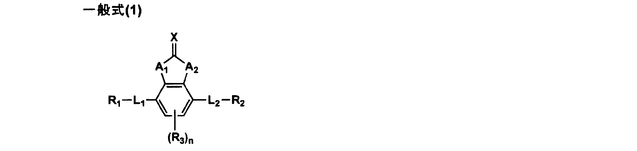
一般式(1)のA1およびA2は、それぞれ独立にO、S、NRX(RXは水素原子または置換基を表す)またはCOを示す。RXで表される置換基の例は、上記WaおよびWbで表される置換基の具体例と同義である。RXは、好ましくは水素原子、アルキル基、アリール基またはヘテロ環基である。
一般式(1)のXは、第3周期以降で第14~16族の非金属原子、または第3周期以降で第14~16族の非金属原子または共役系を含む置換基でありうる。Xは、O、S、NRc、またはC(Rd)Reであることが好ましい。Rc、RdおよびReは置換基を表し、その例には上記WaおよびWbで表される置換基の具体例が挙げられる。
一般式(1)のL1、L2、R1、R2、R3およびnは、一般式(A)のL1、L2、R1、R2、R3およびnと同義である。
以下に、一般式(A)で表される化合物の具体例を示す。
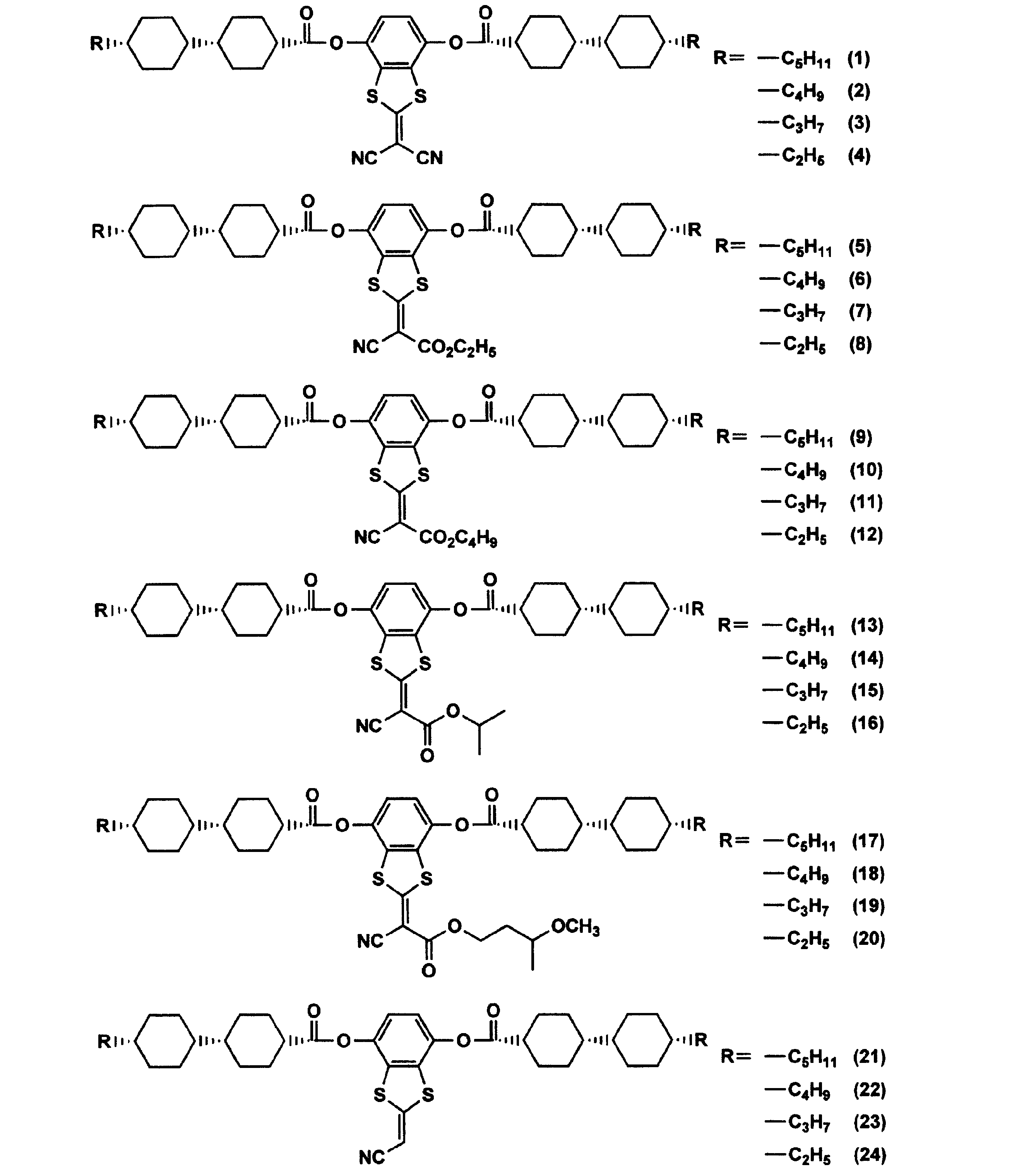
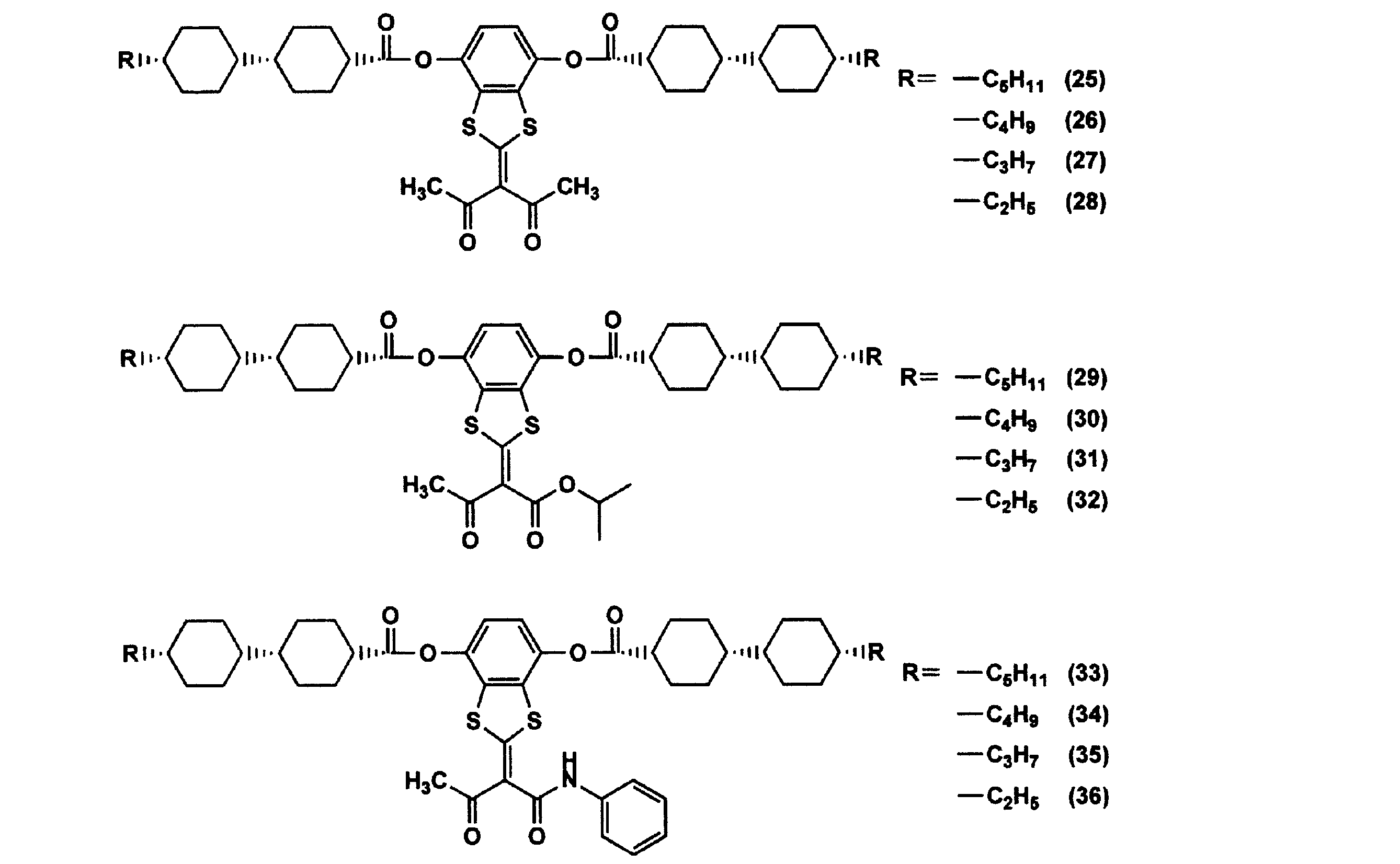
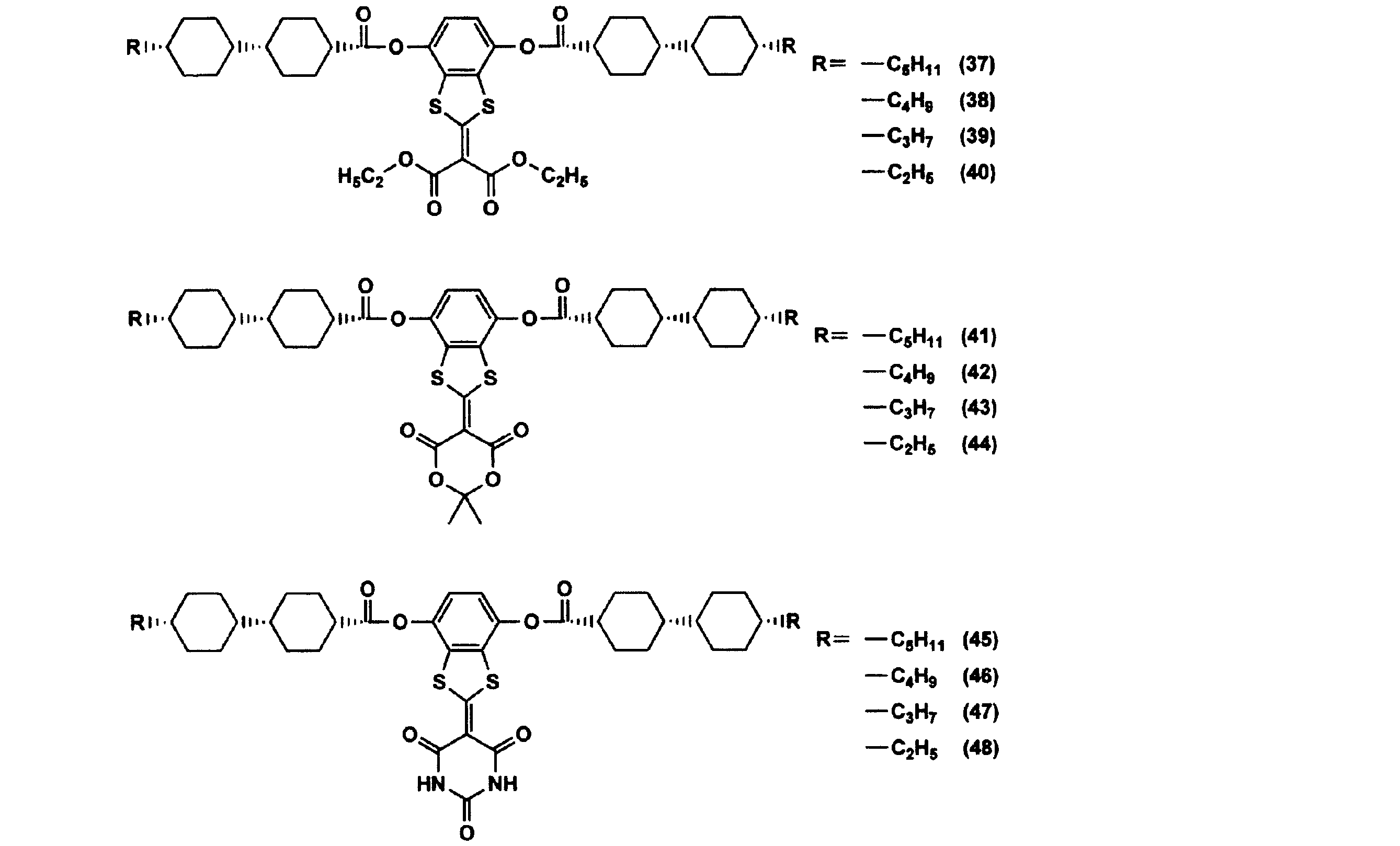
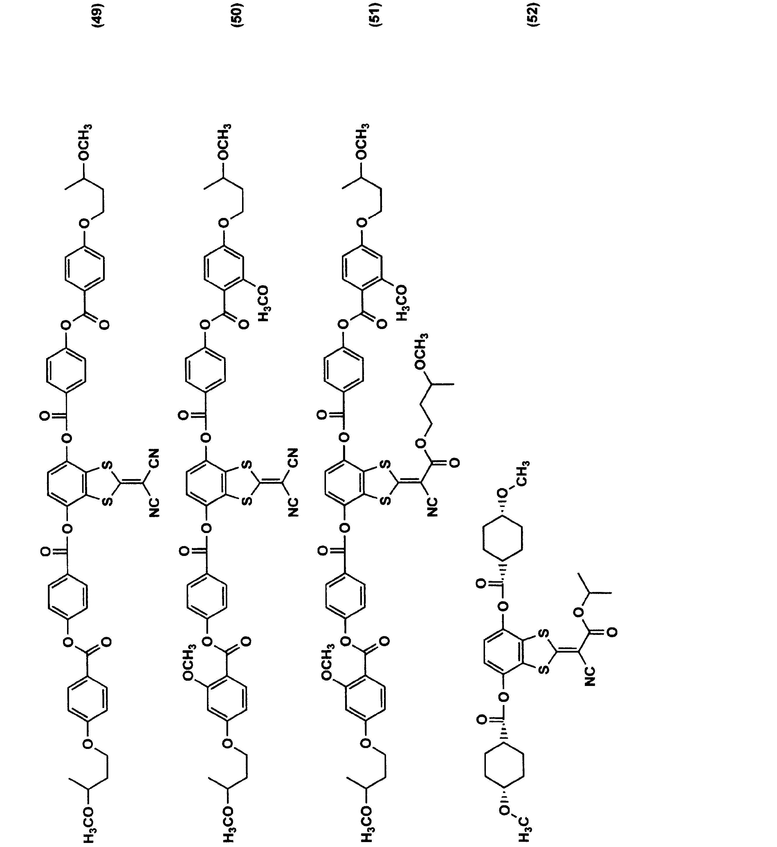
基材層に含まれる波長分散剤の含有量は、所望の波長分散性を付与するためなどから、基材層に含まれるセルロースエステルに対して0.5~15質量%であることが好ましく、1~10質量%であることがより好ましく、2~6質量%であることがさらに好ましい。
基材層に含まれる紫外線吸収剤は、波長370nm以下の紫外線の吸収能に優れ、かつ良好な液晶表示性を得る観点から、波長400nm以上の可視光の吸収が少ない化合物が好ましく用いられる。紫外線吸収剤の例には、ヒンダードフェノール系化合物、オキシベンゾフェノン系化合物、ベンゾトリアゾール系化合物、サリチル酸エステル系化合物、ベンゾフェノン系化合物、シアノアクリレート系化合物、ニッケル錯塩系化合物などが挙げられる。
紫外線吸収剤の具体例には、下記のUV-1~3が含まれる。

紫外線吸収剤の含有量は、セルロースエステルに対して質量割合で1ppm~1.0%が好ましく、10~1000ppmがより好ましい。
本発明の光学フィルムは、表面の滑り性を向上させるためなどから、マット剤(微粒子)をさらに含有してもよい。
基材層に含まれるマット剤(微粒子)は、二酸化ケイ素、二酸化チタン、酸化アルミニウム、酸化ジルコニウム、炭酸カルシウム、カオリン、タルク、焼成ケイ酸カルシウム、水和ケイ酸カルシウム、ケイ酸アルミニウム、ケイ酸マグネシウム、リン酸カルシウム等の無機微粒子や、架橋高分子などの有機微粒子などでありうる。中でも、フィルムのヘイズの増大が少ないことから、二酸化ケイ素の微粒子が好ましい。
微粒子の一次平均粒子径は、20nm以下であることが好ましく、好ましくは5~18nmであり、より好ましくは5~16nmである。微粒子の一次粒子径は、透過型電子顕微鏡にて倍率50万~200万倍で一次粒子を観察し、一次粒子100個の粒子径の平均値として求めることができる。
基材層における微粒子の含有量は、基材層に含まれるセルロースエステルに対して0.05~1.0質量%とすることができ、好ましくは0.1~0.8質量%としうる。
表層について
表層は、アセチル基の置換度が2.6超3.0以下のセルロースアセテートBと、可塑剤とを含む。
表層は、アセチル基の置換度が2.6超3.0以下のセルロースアセテートBと、可塑剤とを含む。
表層に含まれるセルロースアセテートBは、アシル基の全てがアセチル基であり、アシル基の総置換度(アセチル基の置換度)が2.6超3.0以下のセルロースエステルである。このようなセルロースアセテートBを主成分とするフィルムの表面は、アルカリ水溶液による鹸化によって破壊されにくいため、偏光子と光学フィルムの密着性を高めうる。
セルロースアセテートBのアシル基の総置換度(アセチル基の置換度)は、好ましくは2.65以上2.95以下であり、より好ましくは2.7以上2.95以下でありうる。
表層に含まれる可塑剤は、基材層に含まれる可塑剤と同様のものが挙げられる。なかでも、セルロースアセテートBとの相溶性が良好であることから、前述のポリエステル化合物やリン酸エステル化合物が好ましく、前述のポリエステル化合物がより好ましい。
表層に含まれるポリエステル化合物を構成するジカルボン酸は、可とう性を付与してクラックを抑制し、かつセルロースエステルとの相溶性を高めるためには、芳香族ジカルボン酸と脂肪族ジカルボン酸の両方を含むことが好ましい。
表層に含まれるポリエステル化合物の分子末端は、前述と同様に、封止されていてもよい。セルロースエステルとの親和性を高めるためには、ポリエステル化合物の分子末端が未封止であるか、脂肪族モノカルボン酸(好ましくは酢酸)で封止されていることが好ましく;脂肪族モノカルボン酸(好ましくは酢酸)で封止されていることがより好ましい。
表層に含まれるポリエステル化合物の重量平均分子量は、500~2000であることが好ましく、700~2000であることがより好ましい。重量平均分子量が小さすぎるとブリードアウトが生じる可能性がある。重量平均分子量が大きすぎると、セルロースエステルとの相溶性が低下する可能性がある。
本発明の光学フィルムは、後述するように有機EL表示装置の円偏光板のλ/4位相差フィルムとして機能する。そのため、本発明の光学フィルムは、積層フィルムを斜め方向に高倍率で延伸する工程を経て得られる。しかしながら、積層フィルムを斜め方向に高倍率で延伸すると、得られる光学フィルムの表層にクラックが生じることがあった。また、その光学フィルムを有する有機EL表示装置を折り曲げた際に、光学フィルムに斜め方向のシワが生じることがあった。
図1は、有機EL表示装置を折り曲げた際に、光学フィルムに生じる斜め方向のシワの一例を示す模式図である。図1に示されるように、光学フィルム1の折り曲げ軸Cに対して斜め方向(遅相軸方向)にシワが生じる。
このような折り曲げによる斜め方向のシワが生じる原因は、必ずしも明らかではないものの、以下のように推測される。即ち、1)延伸される積層フィルムの引張弾性率が比較的高いこと、2)延伸される積層フィルムの各層の引張弾性率が異なることなどにより、斜め方向に高倍率に延伸された後のフィルムに歪みが残留しやすいと考えられる。この延伸後のフィルムに残留する歪みによって、フィルムを折り曲げた際に、折り曲げ部分に斜め方向にシワが生じると考えられる。
延伸後のフィルムに残留する歪みを少なくするためには、1)延伸される積層フィルムの引張弾性率を低くすることが好ましい。
積層フィルムの引張弾性率を低くするためには、積層フィルムの表層と基材層に可塑剤をそれぞれ含有させることが好ましい。表層における可塑剤の含有量は、セルロースエステルに対して15~50質量%であることが好ましく、25~45質量%であることがより好ましい。それにより、延伸後のフィルムの表層に生じやすいクラックも一層抑制しやすいと考えられる。
しかしながら、1)延伸される積層フィルムの引張弾性率を低くするだけでは、前述のような折り曲げ時の斜め方向のシワを十分には抑制できないことがある。即ち、折り曲げ時の斜め方向のシワを十分に抑制するためには、1)延伸される積層フィルムの引張弾性率を低くするだけでなく;2)延伸される積層フィルムの各層の引張弾性率の差を小さくすることが重要である。
表層と基材層との引張弾性率の差の絶対値は、1GPa以下であることが好ましく、0.5GPa以下であることがより好ましい。表層と基材層の引張弾性率は、JIS K7127に準拠して、オリエンテック社製テンシロンRTC-1225Aを用いて測定することができる。測定条件は、23℃50%RH下、チャック間距離50mmとしうる。
表層と基材層の引張弾性率の差は、表層に含まれる可塑剤の量と基材層に含まれる可塑剤の量との比によって好ましく調整できる。即ち、表層に含まれる可塑剤の量が、基材層に含まれる可塑剤の量よりも多いことが好ましく、基材層に含まれる可塑剤の量の1.2倍以上であることが好ましく、1.4倍以上であることがより好ましい。表層に含まれる可塑剤の量が、基材層に含まれる可塑剤の量に対して多すぎても、表層と基材層の引張弾性率の差を小さくできないことがある。そのため、表層に含まれる可塑剤の量は、基材層に含まれる可塑剤の量の5倍以下であることが好ましく、2.5倍以下であることがより好ましい。
即ち、折り曲げ時の斜め方向のシワを抑制するためには、表層と基材層の両方に可塑剤を含有させ(好ましくは表層に含まれる可塑剤量を一定以上とし)、かつ表層に含まれる可塑剤量の基材層に含まれる可塑剤量に対する比(質量比)を一定以上とすることが好ましい。
表層は、必要に応じて基材層と同様の添加剤をさらに含有してもよい。
基材層および表層は、それぞれ一層のみであってもよいし、二層以上であってもよい。なかでも、薄い膜厚で、かつ歪みを生じにくくするためなどから、光学フィルムは、1つの基材層と、それを挟持する2つの表層とを有すること(3層構造を有すること)が好ましい。
光学フィルムの総厚みは、λ/4位相差フィルムとして十分な位相差を得るためなどから、10~250μmであることが好ましく、より好ましくは15~100μmであり、さらに好ましくは20~80μmであり、特に好ましくは25~65μmでありうる。
光学フィルムの総厚みに対する基材層の厚みの割合は、30~90%の範囲内であることが好ましく、50~85%であることがより好ましい。基材層の厚みの割合が低すぎると、光学フィルムの位相差が十分でないことがある。基材層の厚みの割合が高すぎると、光学フィルム表面の鹸化による破壊を十分には抑制できないことがある。
図2は、光学フィルムの好ましい積層構造の例を示す模式図である。図2に示されるように、光学フィルム10は、基材層11と、それを挟持する一対の表層13および13’とを含む。
表層13および13’の組成や厚みは、互いに同じであっても異なってもよいが、フィルムの反りなどを抑制するためには、表層13および13’の組成や厚みが互いに同じであることが好ましい。
光学フィルムの物性
[面内遅相軸]
本発明では、後述するように、光学フィルムと偏光子とをロールtoロールで貼り合わせて、円偏光板を作製することが好ましい。偏光子は、通常、長尺方向に吸収軸を有する。そのため、光学フィルムは、フィルム面内において、フィルムの幅方向(または長尺方向)に対して斜め方向;好ましくは40~50°;より好ましくは45±2°に遅相軸を有する。
[面内遅相軸]
本発明では、後述するように、光学フィルムと偏光子とをロールtoロールで貼り合わせて、円偏光板を作製することが好ましい。偏光子は、通常、長尺方向に吸収軸を有する。そのため、光学フィルムは、フィルム面内において、フィルムの幅方向(または長尺方向)に対して斜め方向;好ましくは40~50°;より好ましくは45±2°に遅相軸を有する。
光学フィルムの面内遅相軸は、フィルム面内において屈折率が最大となる方向の軸をいい;自動複屈折計Axometric社製のAxoScanなどによって測定することができる。
[引張弾性率の比]
本発明の光学フィルムは、後述するように、λ/4位相差フィルムとして十分な位相差を得るために、斜め方向に高倍率に延伸する工程を経て得られる。そのため、本発明の光学フィルムの斜め方向;即ち、面内遅相軸方向の引張弾性率が高くなっている。具体的には、面内遅相軸方向の引張弾性率Xの、それと直交する方向の引張弾性率Yに対する比X/Yが、好ましくは1.5以上5.0以下であり、より好ましくは1.6以上3.0以下、さらに好ましくは1.7以上2.5以下でありうる。
本発明の光学フィルムは、後述するように、λ/4位相差フィルムとして十分な位相差を得るために、斜め方向に高倍率に延伸する工程を経て得られる。そのため、本発明の光学フィルムの斜め方向;即ち、面内遅相軸方向の引張弾性率が高くなっている。具体的には、面内遅相軸方向の引張弾性率Xの、それと直交する方向の引張弾性率Yに対する比X/Yが、好ましくは1.5以上5.0以下であり、より好ましくは1.6以上3.0以下、さらに好ましくは1.7以上2.5以下でありうる。
引張弾性率の比は、以下の手順で測定することができる。図3は、引張弾性率の測定方法を示す模式図である。図3では、光学フィルムの遅相軸が、TD方向に対して+45°である例について説明する。
1)まず、光学フィルムの遅相軸方向(図3(A)では、TD方向に対して+45°方向)に平行に1cm×10cmのサイズに切り取り、サンプルフィルムS1とする。一方、光学フィルムの遅相軸方向と直交する方向(図3(A)では、TD方向に対して-45°方向)に平行に1cm×10cmのサイズに切り取り、サンプルフィルムS2とする。このサンプルフィルムS1およびS2を、25℃55%RHの環境下で24時間調湿する。
2)次いで、図3(B)に示されるように、調湿後のサンプルフィルムS1を、引張試験機15(オリエンテック社製テンシロンRTC-1225A)にセットし、チャック間距離を50mmとして、JIS K7127に準拠して、サンプルフィルムの長手方向に引っ張り、引張弾性率Xを測定する。
3)同様に、サンプルフィルムS2を長手方向に引っ張って、引張弾性率Yを測定する。引張弾性率の測定は、25℃55%RH下で行うことができる。
4)前記2)および3)で得られた引張弾性率XおよびYを、下記式に当てはめて、引張弾性率の比X/Yを算出する。
引張弾性率の比X/Y=引張弾性率X/引張弾性率Y
1)まず、光学フィルムの遅相軸方向(図3(A)では、TD方向に対して+45°方向)に平行に1cm×10cmのサイズに切り取り、サンプルフィルムS1とする。一方、光学フィルムの遅相軸方向と直交する方向(図3(A)では、TD方向に対して-45°方向)に平行に1cm×10cmのサイズに切り取り、サンプルフィルムS2とする。このサンプルフィルムS1およびS2を、25℃55%RHの環境下で24時間調湿する。
2)次いで、図3(B)に示されるように、調湿後のサンプルフィルムS1を、引張試験機15(オリエンテック社製テンシロンRTC-1225A)にセットし、チャック間距離を50mmとして、JIS K7127に準拠して、サンプルフィルムの長手方向に引っ張り、引張弾性率Xを測定する。
3)同様に、サンプルフィルムS2を長手方向に引っ張って、引張弾性率Yを測定する。引張弾性率の測定は、25℃55%RH下で行うことができる。
4)前記2)および3)で得られた引張弾性率XおよびYを、下記式に当てはめて、引張弾性率の比X/Yを算出する。
引張弾性率の比X/Y=引張弾性率X/引張弾性率Y
[位相差]
本発明の光学フィルムは、23℃55%RHの環境下で、波長550nmで測定される面内方向のレターデーションRo(550)が120~180nmの範囲内であることが好ましく、120~160nmの範囲内であることがより好ましく、130~150nmの範囲内であることがさらに好ましい。厚み方向のレターデーションRthは、40~120nmであることが好ましく、50~100nmであることがより好ましい。このようなレターデーションを有する光学フィルムは、例えば円偏光板のλ/4位相差フィルムとして好適である。
本発明の光学フィルムは、23℃55%RHの環境下で、波長550nmで測定される面内方向のレターデーションRo(550)が120~180nmの範囲内であることが好ましく、120~160nmの範囲内であることがより好ましく、130~150nmの範囲内であることがさらに好ましい。厚み方向のレターデーションRthは、40~120nmであることが好ましく、50~100nmであることがより好ましい。このようなレターデーションを有する光学フィルムは、例えば円偏光板のλ/4位相差フィルムとして好適である。
レターデーションRoおよびRthは、それぞれ以下の式で定義される。
式(I) Ro=(nx-ny)×d
式(II) Rth={(nx+ny)/2-nz}×d
(nx:フィルム面内の遅相軸方向xの屈折率、ny:フィルム面内において、遅相軸方向xに対して直交する方向yの屈折率、nz:フィルムの厚み方向zの屈折率、d:フィルムの厚み(nm))
式(I) Ro=(nx-ny)×d
式(II) Rth={(nx+ny)/2-nz}×d
(nx:フィルム面内の遅相軸方向xの屈折率、ny:フィルム面内において、遅相軸方向xに対して直交する方向yの屈折率、nz:フィルムの厚み方向zの屈折率、d:フィルムの厚み(nm))
レターデーションRoおよびRthは、例えば以下の方法によって測定することができる。
1)光学フィルムを23℃55%RHで調湿する。調湿後の光学フィルムの平均屈折率をアッベ屈折計などで測定する。
2)調湿後の光学フィルムに、当該フィルム表面の法線に平行に測定波長550nmの光を入射させたときのRoを、Axometric社製のAxoScanにて測定する。
3)Axometric社製のAxoScanにより、光学フィルムの面内の遅相軸を傾斜軸(回転軸)として、光学フィルムの表面の法線に対してθの角度(入射角(θ))から測定波長590nmの光を入射させたときのレターデーション値R(θ)を測定する。レターデーション値R(θ)の測定は、θが0°~50°の範囲で、10°毎に6点行うことができる。光学フィルムの面内の遅相軸は、Axometric社製のAxoScanにより確認することができる。
4)測定されたRoおよびR(θ)と、前述の平均屈折率と膜厚とから、Axometric社製のAxoScanにより、nx、nyおよびnzを算出して、測定波長590nmでのRthを算出する。レターデーションの測定は、23℃55%RH条件下で行うことができる。
1)光学フィルムを23℃55%RHで調湿する。調湿後の光学フィルムの平均屈折率をアッベ屈折計などで測定する。
2)調湿後の光学フィルムに、当該フィルム表面の法線に平行に測定波長550nmの光を入射させたときのRoを、Axometric社製のAxoScanにて測定する。
3)Axometric社製のAxoScanにより、光学フィルムの面内の遅相軸を傾斜軸(回転軸)として、光学フィルムの表面の法線に対してθの角度(入射角(θ))から測定波長590nmの光を入射させたときのレターデーション値R(θ)を測定する。レターデーション値R(θ)の測定は、θが0°~50°の範囲で、10°毎に6点行うことができる。光学フィルムの面内の遅相軸は、Axometric社製のAxoScanにより確認することができる。
4)測定されたRoおよびR(θ)と、前述の平均屈折率と膜厚とから、Axometric社製のAxoScanにより、nx、nyおよびnzを算出して、測定波長590nmでのRthを算出する。レターデーションの測定は、23℃55%RH条件下で行うことができる。
光学フィルムの、JIS K-7136に準拠して測定される内部ヘイズは、0.01~0.1であることが好ましい。光学フィルムの可視光透過率は、90%以上であることが好ましく、93%以上であることがより好ましい。
2.光学フィルムの製造方法
本発明の光学フィルムは、1)前述のセルロースアセテートプロピオネートA1またはセルロースアセテートA2と可塑剤とを含有する第一の層(基材層となる層)と、その少なくとも一方の面に配置され、セルロースアセテートBと可塑剤とを含有する第二の層(表層となる層)とを含む積層フィルムを得る工程;2)積層フィルムを、少なくとも幅方向に対して斜め方向に1.5倍以上3.0倍以下の倍率で延伸して、前述の基材層と表層とを含む光学フィルムを得る工程を経て得ることができる。
本発明の光学フィルムは、1)前述のセルロースアセテートプロピオネートA1またはセルロースアセテートA2と可塑剤とを含有する第一の層(基材層となる層)と、その少なくとも一方の面に配置され、セルロースアセテートBと可塑剤とを含有する第二の層(表層となる層)とを含む積層フィルムを得る工程;2)積層フィルムを、少なくとも幅方向に対して斜め方向に1.5倍以上3.0倍以下の倍率で延伸して、前述の基材層と表層とを含む光学フィルムを得る工程を経て得ることができる。
1)積層フィルムを得る工程は、製造が比較的容易であることなどから、共流延法で行うことが好ましい。共流延法は、溶液流延法であっても溶融流延法であってもよく、面状が良好な光学フィルムが得られやすいことから、好ましくは溶液流延法でありうる。
即ち、1)積層フィルムを得る工程は、1-1)前述のセルロースアセテートプロピオネートA1またはセルロースアセテートA2、可塑剤および有機溶媒を含有する第一のドープ(基材層用ドープ)と、前述のセルロースアセテートB、可塑剤および有機溶媒を含有する第二のドープ(表層用ドープ)とを得る工程;1-2)第一および第二のドープを、流延支持体上に同時または逐次に積層しながら流延する工程;1-3)積層された第一および第二のドープ中の有機溶媒を除去して積層フィルムを得る工程、を含むことが好ましい。
1-1)ドープを準備する工程
セルロースエステル、可塑剤、および必要に応じて他の成分を有機溶媒に溶解させて、セルロースエステルを主成分とする第一のドープ(基材層用ドープ)と第二のドープ(表層用ドープ)を得る。
セルロースエステル、可塑剤、および必要に応じて他の成分を有機溶媒に溶解させて、セルロースエステルを主成分とする第一のドープ(基材層用ドープ)と第二のドープ(表層用ドープ)を得る。
ドープの調製に用いられる有機溶媒は、従来公知の有機溶媒であってよく、例えば溶解度パラメーターで17~22の範囲ものが好ましい。溶解度パラメーターは、例えばJ.Brandrup、E.H等の「PolymerHandbook(4th.edition)」、VII/671~VII/714に記載の内容のものを表す。低級脂肪族炭化水素の塩化物、低級脂肪族アルコール、炭素原子数3~12までのケトン、炭素原子数3~12のエステル、炭素原子数3~12のエーテル、炭素原子数5~8の脂肪族炭化水素類、炭素数6~12の芳香族炭化水素類、フルオロアルコール類(例えば、特開平8-143709号公報 段落番号[0020]、同11-60807号公報 段落番号[0037]等に記載の化合物)等が挙げられる。
有機溶媒は、一種類で用いられてもよいが、二種類以上を組み合わせてもよい。二種類以上を組み合わせる場合、面状が良好な光学フィルムを安定に得るために、良溶剤と貧溶剤を混合して使用することが好ましい。良溶剤と貧溶剤の混合比率は、良溶剤が60~99質量%であり、貧溶剤が40~1質量%であることが好ましい。
良溶剤とは、使用する樹脂を単独で溶解するもの、貧溶剤とは使用する樹脂を単独で膨潤するかまたは溶解しないものをいう。良溶剤の例には、メチレンクロライド等の有機ハロゲン化合物やジオキソラン類が含まれる。貧溶剤の例には、メタノール、エタノール、n-ブタノール、シクロヘキサン等が好ましく用いられる。
第一および第二のドープに含まれる貧溶媒は、流延支持体上でのドープの乾燥時間を短縮するためなどから、アルコールであることが好ましく、メタノールであることが好ましい。基材層用ドープAおよび表層用ドープBに含まれる有機溶媒のうちメタノールの含有割合は20~35質量%とすることができ、好ましくは21~35質量%、より好ましくは25~30質量%としうる。
第一および第二のドープの固形分濃度(ドープを乾燥した後、固体となる成分の濃度)は、樹脂の分子量に応じて適切に設定されうる。溶液流延製膜を行うのに適切な粘度のドープを得るためには、固形分濃度が16~30質量%であることが好ましく、18~25質量%であることがより好ましい。
共流延製膜にて良好な面状のフィルムを得るためには、第一および第二のドープの固形分濃度が同程度であることが好ましい。第一および第二のドープの固形分濃度の差が10質量%以内であることが好ましく、5質量%以内であることがより好ましい。
各成分の有機溶媒への溶解は、室温溶解法、冷却溶解法または高温溶解方法で行うことができる。セルロースエステルの有機溶媒への溶解方法は、例えば特開平5-163301号公報などに記載されている。高温で溶解する場合は、使用する有機溶媒の沸点以上かつ加圧状態で行うことが好ましい。
得られたドープは、必要に応じて溶液濃縮および濾過されうる。溶液濃縮および濾過方法は、公技番号2001-1745号公報の25頁に詳細に記載されている。
1-2)同時または逐次に積層しながら流延する工程
第一および第二のドープを、流延支持体上に同時または逐次に積層しながら流延する。
第一および第二のドープを、流延支持体上に同時または逐次に積層しながら流延する。
第一および第二のドープの共流延は、公知の共流延方法で行うことができる。例えば、流延支持体の進行方向に間隔を置いて設けた複数の流延口から各ドープをそれぞれ逐次流延させて積層させてもよく、例えば特開昭61-158414号、特開平1-122419号、特開平11-198285号の各公報などに記載の方法が適用できる。また、2つの流延口からドープを同時に流延して積層させてもよく、例えば特公昭60-27562号、特開昭61-94724号、特開昭61-947245号、特開昭61-104813号、特開昭61-158413号、特開平6-134933号の各公報に記載の方法を適用できる。
例えば、表層/基材層/表層の3層構造を有する光学フィルムを得る場合、流延支持体側から順に、第二のドープ(表層用ドープ)/第一のドープ(基材層用ドープ)/第二のドープ(表層用ドープ)を共流延することができる。積層物における複数の第二のドープの組成は、互いに同一であってもよいし、異なっていてもよい。
流延支持体は、特に制限はないが、ドラムまたはバンドであることが好ましい。支持体の表面は、鏡面状態に仕上げておくことが好ましい。ソルベントキャスト法における流延及び乾燥方法については、米国特許2336310号などに記載されている。
第一および第二のドープが流延される流延支持体の表面温度は、5℃以下であることが好ましく、-30~5℃であることがより好ましく、-10~2℃であることがさらに好ましい。
1-3)ドープに含まれる有機溶媒を除去して、積層フィルムを得る工程
流延された第一および第二のドープを、温調板で加熱して乾燥させてもよいし;2秒以上風に当てて乾燥させてもよい。得られた積層フィルムを流延支持体から剥ぎ取り、100℃から160℃まで逐次温度を変えながら高温風で乾燥させて残留溶媒を蒸発させてもよい。この乾燥方法は、特公平5-17844号公報に記載されている。
流延された第一および第二のドープを、温調板で加熱して乾燥させてもよいし;2秒以上風に当てて乾燥させてもよい。得られた積層フィルムを流延支持体から剥ぎ取り、100℃から160℃まで逐次温度を変えながら高温風で乾燥させて残留溶媒を蒸発させてもよい。この乾燥方法は、特公平5-17844号公報に記載されている。
2)積層フィルムを延伸する工程
前述の積層フィルムを、少なくともフィルムの幅方向(または長尺方向)に対して斜め方向に高倍率で延伸して、基材層とその少なくとも一方の面上に配置された表層とを含む光学フィルムを得る。斜め延伸は、製膜された積層フィルムを巻き取らずに連続的に行ってもよいし;製膜された積層フィルムを一旦巻き取った後、巻き出して行ってもよい。
前述の積層フィルムを、少なくともフィルムの幅方向(または長尺方向)に対して斜め方向に高倍率で延伸して、基材層とその少なくとも一方の面上に配置された表層とを含む光学フィルムを得る。斜め延伸は、製膜された積層フィルムを巻き取らずに連続的に行ってもよいし;製膜された積層フィルムを一旦巻き取った後、巻き出して行ってもよい。
積層フィルムの延伸開始時の残留溶媒量は、1~50質量%であることが好ましく、10~50質量%であることがより好ましく、12~35質量%であることがさらに好ましい。残留溶媒量が1%未満である積層フィルムを延伸すると、延伸が困難になるだけでなく、フィルムが破断する場合があり好ましくない。残留溶媒量が50%を超えて延伸した場合、弾性率増加の効果が小さくなってしまい、十分な表面硬度が得られない。
なお、残留溶媒量は下記の式で表される。
残留溶媒量(質量%)={(M-N)/N}×100
Mは積層物の任意時点での質量、NはMを測定した積層物を110℃で3時間乾燥させた時の質量である。
残留溶媒量(質量%)={(M-N)/N}×100
Mは積層物の任意時点での質量、NはMを測定した積層物を110℃で3時間乾燥させた時の質量である。
延伸は、前述の通り、少なくともフィルムの幅方向(または長尺方向)に対して斜め方向に行うことが好ましい。それにより、ロール体から巻き出され、フィルムの長尺方向に吸収軸を有する偏光子と、ロール体から巻き出され、フィルムの長尺方向に対して斜め方向に遅相軸を有する光学フィルムとを、長尺方向が互いに重なり合うようにロールtoロールで貼り合わせするだけで、円偏光板を容易に製造できる。そのため、フィルムのカットロスが少なくすることができ、生産上有利である。
フィルムの幅方向(または長尺方向)に対して斜め方向とは、具体的にはフィルムの幅方向(または長尺方向)に対して40~50°の方向であり;好ましくは45±2°の方向をいう。必要に応じて、斜め方向の延伸と、幅方向または長手方向の延伸とを組み合わせてもよい。
斜め方向の延伸倍率は、λ/4位相差フィルムとして十分な位相差を得るためなどから、1.5倍以上3.0倍以下であることが好ましく、1.7倍以上2.3倍以下であることがより好ましい。
前述の通り、延伸される積層フィルムに一定以上の可塑剤を含有させることで、積層フィルムの引張弾性率を低くすることができ、表層にクラックが生じるのを抑制できる。
斜め方向の延伸は、斜め延伸機により行うことができる。斜め延伸機は、通常、フィルムの幅方向両端側に配置された一対のレールと、該レール上を走行し、フィルムの幅方向両端部を把持する多数の把持具とを有している。
一対のレールは、それぞれ無端状の連続軌道を有し、テンターの出口部でフィルムの把持を開放した把持具は、外側を走行して順次入口部に戻されるようになっている。一対のレールのレールパターンは、左右で非対称な形状となっており、製造すべき長尺延伸フィルムに与える配向角θ、延伸倍率等に応じて、そのレールパターンは調整できるようになっている。
図4は、斜め延伸機のレールパターンの一例を示す概略図である。図4に示されるように、通常、斜め延伸機では、長尺のフィルム原反の繰出方向D1と、延伸後の延伸フィルムの巻取方向D2とは異なっており、繰出角度θiをなしている。繰出し角度θiは、0°超90°未満の範囲で、所望の角度に任意に設定することができる。
斜め延伸機の入口(図中Aの位置)では、前述の長尺状の積層フィルムの両端部を、左右の把持具(テンター)で把持して走行させる。左右の把持具は、斜め延伸機の入口(図中Aの位置)で、フィルムの搬送方向(繰出方向D1)に対して略直交する方向に対向している左右の把持具CiおよびCoは、それぞれ互いに非対称な形状のレールRi、Ro上を走行する。そして、左右の把持具は、延伸終了時の位置(図中Bの位置)で、把持したフィルムを解放する。
斜め延伸機入口(図中Aの位置)で対向していた左右の把持具は、左右非対称なレールRi、Ro上を走行するにつれて、Ri側を走行する把持具Ciは、Ro側を走行する把持具Coに対して進行する。即ち、斜め延伸機入口(フィルムの把持具による把持開始位置)Aでは、把持具CiおよびCoを結んだ直線が、フィルムの繰出方向D1に対して略垂直となる。一方、フィルムの延伸終了時の位置Bにある状態では、該把持具CiおよびCoを結んだ直線が、フィルムの巻取方向D2に対して略垂直な方向に対して角度θLだけ傾斜している。それにより、積層フィルムがθLの方向に斜め延伸されることとなる。略垂直とは、90±1°の範囲にあることを示す。
そして、一対のレール間に形成されるゾーンのうち、両端を把持した把持具の間隔が一定の間隔を保ったまま走行する区間が「予熱ゾーン」となる。また、両端を把持した把持具の間隔が開きだし、所定の間隔になるまでの区間が「延伸ゾーン」となる。さらに、延伸ゾーンより後の把持具の間隔が再び一定となる期間において、両端の把持具が互いに平行を保ったまま走行する区間が「熱固定ゾーンまたは熱固定・冷却ゾーン」となる。
予熱ゾーンと延伸ゾーンの温度は、セルロースエステルのガラス転移温度をTgとしたとき、Tg~Tg+30℃の範囲内とすることが好ましく;熱固定ゾーンまたは熱固定・冷却ゾーンの温度は、Tg-30~Tg℃の範囲内に設定することが好ましい。
予熱ゾーン、延伸ゾーン、熱固定ゾーンの長さは、適宜選択されうる。予熱ゾーンの長さは、延伸ゾーンの長さに対して、通常100~150%の範囲内とすることができ;熱固定ゾーンの長さは、通常、50~100%の範囲内とすることができる。
図5は、レールパターンの異なる斜め延伸機の例を示す模式図である。図5の(a)~(c)の斜め延伸機20は、フィルム繰り出し装置21と、搬送方向変更装置23と、巻き取り装置25とを有する。
得られた長尺状の光学フィルムを、巻き取り機を用いて、フィルムの長尺方向(幅方向に対して垂直方向)に巻き取る。巻き取り方法は、特に制限されず、定トルク法、定テンション法、テーパーテンション法などでありうる。光学フィルムを巻き取る際の、巻き取り張力は、50~170N程度としうる。
3.円偏光板
本発明の偏光板は、偏光子と、その一方の面に配置された、本発明の光学フィルムとを含む。
本発明の偏光板は、偏光子と、その一方の面に配置された、本発明の光学フィルムとを含む。
偏光子は、一定方向の偏波面の光のみを通過させる素子である。偏光子の代表的な例は、ポリビニルアルコール系偏光フィルムであり、ポリビニルアルコール系フィルムにヨウ素を染色させたものと、二色性染料を染色させたものと、がある。
偏光子は、ポリビニルアルコールフィルムを一軸延伸した後、染色するか;あるいはポリビニルアルコールフィルムを染色した後、一軸延伸して、好ましくはホウ素化合物で耐久性処理をさらに行って得ることができる。偏光子の膜厚は、5~30μmの範囲内が好ましく、5~20μmの範囲内であることがより好ましい。
ポリビニルアルコールフィルムとしては、特開2003-248123号公報、特開2003-342322号公報等に記載のエチレン単位の含有量1~4モル%、重合度2000~4000、ケン化度99.0~99.99モル%のエチレン変性ポリビニルアルコールが好ましく用いられる。
本発明の光学フィルムは、偏光子の一方の面に配置されている。そして、本発明の光学フィルムの面内遅相軸は、偏光子の吸収軸に対して好ましくは40~50°;より好ましくは45±2°をなしている。
偏光子の他方の面には、保護フィルムがさらに配置されていることが好ましい。保護フィルムの例には、市販のセルロースエステルフィルム、例えば、コニカミノルタタック KC8UX、KC5UX、KC4UX、KC8UCR3、KC4SR、KC4BR、KC4CR、KC4DR、KC4FR、KC4KR、KC8UY、KC6UY、KC4UY、KC4UE、KC8UE、KC8UY-HA、KC2UA、KC4UA、KC6UAKC、2UAH、KC4UAH、KC6UAH(以上コニカミノルタアドバンストレイヤー(株)製);フジタックT40UZ、フジタックT60UZ、フジタックT80UZ、フジタックTD80UL、フジタックTD60UL、フジタックTD40UL、フジタックR02、フジタックR06(以上富士フイルム(株)製)が含まれる。
本発明の円偏光板は、偏光子と本発明の光学フィルムとを接着剤を介して貼り合わせる工程を経て得ることができる。
本発明の光学フィルムは、フィルムの幅方向(または長手方向)に対して斜め方向に面内遅相軸を有する。そのため、フィルムの長手方向に吸収軸を有する偏光子の長手方向と、光学フィルムの長手方向とが重なり合うようにロールtoロールで貼り合わせるだけで、偏光子の円偏光板を容易に製造することができる。
貼り合わせに用いられる接着剤は、完全鹸化型のポリビニルアルコ-ル系接着剤などの水系接着剤や活性エネルギー線硬化性接着剤などであり、好ましくは水系接着剤である。
本発明の光学フィルムの表層は、前述のセルロースアセテートBを主成分として含むため、水系接着剤を用いて偏光子と接着させる前に行う鹸化処理によって、破壊されにくい。そのため、本発明の光学フィルムは、水系接着剤を介して偏光子と良好に密着しうる。
また、水系接着剤だけでなく、得られる偏光板の透湿性を効果的に制御できる点などから、活性エネルギー線硬化性接着剤を用いてもよい。活性エネルギー線硬化性接着剤を用いて偏光板を作製する場合、活性エネルギー線硬化性接着剤は、紫外線光の増感剤をさらに含むことが好ましい。
活性エネルギー線硬化性接着剤に含まれる硬化性化合物は、カチオン重合型化合物またはラジカル重合型化合物であり、接着性を高める観点では、カチオン重合性化合物(例えばエポキシ化合物)が好ましい。また、活性エネルギー線硬化性接着剤は、380nmより長い波長の光に極大吸収を示す光増感剤をさらに含有することが好ましい。活性エネルギー線硬化性接着剤の組成は、例えば特開2011-28234号公報に記載されている。
4.有機EL表示装置
本発明の有機EL表示装置は、有機EL素子と、その視認側の面に配置された本発明の円偏光板とを有する。
本発明の有機EL表示装置は、有機EL素子と、その視認側の面に配置された本発明の円偏光板とを有する。
図6は、有機EL表示装置の基本的な構成の一例を示す模式図である。図6に示されるように、有機EL表示装置30は、有機EL素子50と、その視認側の面に配置された本発明の円偏光板70とを有する。
有機EL素子50は、基板51、金属電極53、TFT55、有機発光層57、透明電極(ITO等)59、絶縁層61、封止層63およびフィルム65(省略可)をこの順に有しうる。
基板51は、ガラス基板またはポリイミド等のプラスチックフィルムなどでありうる。中でも、有機EL表示装置30がフレキシブルタイプである場合、基板51は、可とう性を有するガラスフィルムまたは樹脂フィルムであることが好ましい。
金属電極53は、陰極として機能し、光反射率の高い金属材料で構成されていることが好ましい。金属材料の例には、Mg、MgAg、MgIn、Al、LiAl等が含まれる。
有機発光層57は、種々の有機薄膜の積層物であってよく、例えばトリフェニルアミン誘導体等からなる正孔注入層/アントラセン等の蛍光性の有機固体からなる発光層の積層物;アントラセン等の蛍光性の有機固体からなる発光層/ペリレン誘導体等からなる電子注入層の積層物;上記正孔注入層/上記発光層/上記電子注入層の積層物などでありうる。有機発光層57の厚みは、10nm程度でありうる。このため、有機発光層57も、透明電極59と同様、光をほぼ完全に透過する。
透明電極59は、陽極であり、有機発光層57での発光を取り出すために、酸化インジウムスズ(ITO)などの透明導電体で構成されている。
フィルム65は、光を透過させうるもの(透明なもの)であればよく、ガラス基板、プラスチックフィルムまたは薄膜などでありうる。中でも、有機EL表示装置30がフレキシブルタイプである場合、フィルム65は、可とう性を有するガラスフィルムまたは樹脂フィルムであることが好ましい。
そして、有機EL素子50は、透明電極59と金属電極53との間に電圧を印加することで、有機発光層57に正孔と電子とを注入し、これら正孔と電子との再結合によって発光する。
円偏光板70は、偏光子71と、偏光子71の有機EL素子50側の面に配置される本発明の光学フィルム73と、偏光子71の視認側の面に配置される保護フィルム75とを有する。
本発明の光学フィルム73は、前述の基材層73-1と、その両面に配置された表層73-3および73-3’とを有する。
図7は、円偏光板70による反射防止機能を説明する模式図である。図7において、図6と同じ部材は、同一の符号を付する。まず、有機EL表示装置の表示画面の法線に平行に、外部から光(a1およびb1を含む)が入射すると、偏光子(LP)71の透過軸方向と平行な直線偏光(b1)のみが偏光子(LP)71を通過する。偏光子(LP)71の透過軸方向と平行でない他の直線偏光(a1)は、偏光子(LP)71に吸収される。偏光子(LP)71を通過した直線偏光成分(b2)は、光学フィルム73を通過することで、円偏光(c2)に変換される。円偏光(c2)は、フィルム65、封止層63、絶縁層61、透明電極59、有機発光層57、TFT55を透過し、金属電極53(図6参照)で反射されて逆回りの円偏光(c3)となる。逆回りの円偏光(c3)は、TFT55、有機発光層57、透明電極59、絶縁層61、封止層63およびフィルム65を通過し、さらに光学フィルム73を通過することで偏光子(LP)71の透過軸方向に対して直交する方向の直線偏光(b3)に変換される。この直線偏光(b3)は、偏光子(LP)71を通過できずに、吸収される。
このように、有機EL表示装置に外部から入射する光(a1およびb1を含む)は、すべて偏光子(LP)71に吸収されるため、有機EL表示装置の金属電極53で反射しても、外部に出射しない。したがって、背景の映り込みによる画像表示特性の低下を防止することができる。
そして、本発明の光学フィルム73は、基材層73-1と、その両面に配置された表層73-3の引張弾性率の差が小さいため(図6参照)、高倍率で斜め延伸されることにより残留する歪みが少ない。そのため、本発明の光学フィルム73を含む有機EL表示装置30を折り曲げた時の、図1に示されるような斜め方向のシワの発生を抑制できる。
以下において、実施例を参照して本発明をより詳細に説明する。これらの実施例によって、本発明の範囲は限定して解釈されない。
1.光学フィルムの材料
1)セルロースエステル
下記表のセルロースエステルを準備した。下記表において、Dacはアセチル基置換度、Dprはプロピオニル基置換度、Dallは総置換度をそれぞれ示す。

1)セルロースエステル
下記表のセルロースエステルを準備した。下記表において、Dacはアセチル基置換度、Dprはプロピオニル基置換度、Dallは総置換度をそれぞれ示す。
2)可塑剤
下記表のポリエステル化合物を準備した。

下記表のポリエステル化合物を準備した。
3)波長分散調整剤
下記化合物(24)

下記化合物(24)
(実施例1)
ドープの調製
下記成分を密閉容器に投入し、加熱および攪拌しながら、完全に溶解させた。得られた溶液を、安積濾紙(株)製の安積濾紙No.24にて濾過した後、日本精線(株)製のファインメットNFにてさらに濾過して、基材層用ドープ液を得た。
(基材層用ドープの組成)
CAP1:100質量部
PE-A:10質量部
波長分散調整剤 上記化合物(24):4.0質量部
マット剤分散液(AEROSIL R972、日本エアロジル株式会社製、2次平均粒子サイズ1.0μm以下):セルロースエステル100質量部に対して固形分0.13質量部
ジクロロメタン:406質量部
メタノール:61質量部
ブタノール:2質量部
ドープの調製
下記成分を密閉容器に投入し、加熱および攪拌しながら、完全に溶解させた。得られた溶液を、安積濾紙(株)製の安積濾紙No.24にて濾過した後、日本精線(株)製のファインメットNFにてさらに濾過して、基材層用ドープ液を得た。
(基材層用ドープの組成)
CAP1:100質量部
PE-A:10質量部
波長分散調整剤 上記化合物(24):4.0質量部
マット剤分散液(AEROSIL R972、日本エアロジル株式会社製、2次平均粒子サイズ1.0μm以下):セルロースエステル100質量部に対して固形分0.13質量部
ジクロロメタン:406質量部
メタノール:61質量部
ブタノール:2質量部
一方、下記成分を別の密閉容器に投入し、加熱および攪拌しながら、完全に溶解させた。得られた溶液を、前述と同様に濾過し、表層用ドープ液を得た。
(表層用ドープの組成)
TAC1:100質量部
PE-A:20質量部
マット剤分散液(AEROSIL R972、日本エアロジル株式会社製、2次平均粒子サイズ1.0μm以下):セルロースエステル100質量部に対して固形分0.13質量部
ジクロロメタン:406質量部
メタノール:61質量部
ブタノール:2質量部
(表層用ドープの組成)
TAC1:100質量部
PE-A:20質量部
マット剤分散液(AEROSIL R972、日本エアロジル株式会社製、2次平均粒子サイズ1.0μm以下):セルロースエステル100質量部に対して固形分0.13質量部
ジクロロメタン:406質量部
メタノール:61質量部
ブタノール:2質量部
光学フィルムの作製
得られた基材層用ドープと表層用ドープを、ベルト流延装置を用いて、表層用ドープ/基材層用ドープ/表層用ドープの順に積層されるように同時多層流延させた。ベルト上に流延したドープを、残留溶剤量が約30質量%となるまで乾燥させた後、ベルトから剥ぎ取って膜状物を得た。
得られた基材層用ドープと表層用ドープを、ベルト流延装置を用いて、表層用ドープ/基材層用ドープ/表層用ドープの順に積層されるように同時多層流延させた。ベルト上に流延したドープを、残留溶剤量が約30質量%となるまで乾燥させた後、ベルトから剥ぎ取って膜状物を得た。
得られた膜状物を、140℃の熱風で残留溶媒量が1.0%未満になるまで乾燥させた後、フィルムを巻き取った。次いで、巻き取ったフィルムを繰り出して、180℃で2.0倍の延伸倍率でフィルムの幅方向に対して45°の方向に延伸した。それにより、表層/基材層/表層の3層構造を有する光学フィルム101を得た。得られた光学フィルム101の総厚みは41μmであり、各層の厚みは表層/基材層/表層=3μm/35μm/3μmであった。
(比較例1~2)
延伸倍率を表4に示されるように変更した以外は実施例1と同様にして光学フィルム102~103を得た。
延伸倍率を表4に示されるように変更した以外は実施例1と同様にして光学フィルム102~103を得た。
(実施例2~6、比較例3~4)
表層に含まれる可塑剤量の、基材層に含まれる可塑剤量に対する比(可塑剤含有比)を、表4に示されるように変更した以外は実施例1と同様にして光学フィルム104~110を得た。
表層に含まれる可塑剤量の、基材層に含まれる可塑剤量に対する比(可塑剤含有比)を、表4に示されるように変更した以外は実施例1と同様にして光学フィルム104~110を得た。
(実施例7)
基材層に波長分散剤を含有させなかった以外は実施例1と同様にして光学フィルム111を得た。
基材層に波長分散剤を含有させなかった以外は実施例1と同様にして光学フィルム111を得た。
(実施例8~10、比較例5~7)
基材層または表層に含まれるセルロースエステルの種類を表4に示されるように変更した以外は実施例1と同様にして光学フィルム112~117を得た。
基材層または表層に含まれるセルロースエステルの種類を表4に示されるように変更した以外は実施例1と同様にして光学フィルム112~117を得た。
(実施例11~14)
基材層または表層に含まれる可塑剤の種類を表4に示されるように変更した以外は実施例1と同様にして光学フィルム118~121を得た。
基材層または表層に含まれる可塑剤の種類を表4に示されるように変更した以外は実施例1と同様にして光学フィルム118~121を得た。
(実施例15~16)
各層の厚み比および総厚みを表4に示されるように変更した以外は実施例1と同様にして光学フィルム122~123を得た。
各層の厚み比および総厚みを表4に示されるように変更した以外は実施例1と同様にして光学フィルム122~123を得た。
(実施例17~23)
表層に含まれる可塑剤の種類を表5に示されるように変更した以外は実施例1と同様にして光学フィルム124~130を得た。
表層に含まれる可塑剤の種類を表5に示されるように変更した以外は実施例1と同様にして光学フィルム124~130を得た。
(実施例24、比較例8~9)
表層と基材層に含まれる可塑剤の量を表5に示されるようにそれぞれ変更した以外は実施例1と同様にして光学フィルム131~133を得た。
表層と基材層に含まれる可塑剤の量を表5に示されるようにそれぞれ変更した以外は実施例1と同様にして光学フィルム131~133を得た。
得られた光学フィルムの面内の弾性率比、表層と基材層の弾性率差、クラック、平面性およびレターデーションを、以下の方法で評価した。
[面内の弾性率比]
1)まず、図3(A)に示されるように、光学フィルムの遅相軸方向(TD方向に対して+45°方向)に平行に1cm×10cmのサイズに切り取り、サンプルフィルムS1とした。一方、光学フィルムの遅相軸方向と直交する方向(TD方向に対して-45°方向)に平行に1cm×10cmのサイズに切り取り、サンプルフィルムS2とした。このサンプルフィルムS1およびS2を、25℃55%RHの環境下で24時間調湿した。
2)次いで、調湿後のサンプルフィルムS1を、JIS K7127に準拠して、オリエンテック社製テンシロンRTC-1225Aを用いて、チャック間距離を50mmとし、サンプルフィルムの長手方向(遅相軸方向)に引っ張り、遅相軸方向の引張弾性率Xを測定した。
3)同様に、サンプルフィルムS2を、長手方向(遅相軸方向と直交する方向)に引っ張って、遅相軸方向と直交する方向の引張弾性率Yを測定した。引張弾性率の測定は、25℃55%RH下で行った。
4)前記2)および3)で得られた引張弾性率XおよびYを、下記式に当てはめて、引張弾性率の比X/Yを算出した。
引張弾性率の比X/Y=引張弾性率X/引張弾性率Y
1)まず、図3(A)に示されるように、光学フィルムの遅相軸方向(TD方向に対して+45°方向)に平行に1cm×10cmのサイズに切り取り、サンプルフィルムS1とした。一方、光学フィルムの遅相軸方向と直交する方向(TD方向に対して-45°方向)に平行に1cm×10cmのサイズに切り取り、サンプルフィルムS2とした。このサンプルフィルムS1およびS2を、25℃55%RHの環境下で24時間調湿した。
2)次いで、調湿後のサンプルフィルムS1を、JIS K7127に準拠して、オリエンテック社製テンシロンRTC-1225Aを用いて、チャック間距離を50mmとし、サンプルフィルムの長手方向(遅相軸方向)に引っ張り、遅相軸方向の引張弾性率Xを測定した。
3)同様に、サンプルフィルムS2を、長手方向(遅相軸方向と直交する方向)に引っ張って、遅相軸方向と直交する方向の引張弾性率Yを測定した。引張弾性率の測定は、25℃55%RH下で行った。
4)前記2)および3)で得られた引張弾性率XおよびYを、下記式に当てはめて、引張弾性率の比X/Yを算出した。
引張弾性率の比X/Y=引張弾性率X/引張弾性率Y
[表層と基材層の弾性率差]
表層を構成する材料からなる厚み30μmのフィルムと、基材層を構成する材料からなる厚み30μmのフィルムの引張弾性率を、それぞれJIS K7127に準拠して、オリエンテック社製テンシロンRTC-1225Aを用いて測定した。測定条件は、23℃50%RH下、チャック間距離50mmとした。得られた引張弾性率の値から、表層と基材層の弾性率差(=表層の引張弾性率-基材層の引張弾性率)を求めた。
表層を構成する材料からなる厚み30μmのフィルムと、基材層を構成する材料からなる厚み30μmのフィルムの引張弾性率を、それぞれJIS K7127に準拠して、オリエンテック社製テンシロンRTC-1225Aを用いて測定した。測定条件は、23℃50%RH下、チャック間距離50mmとした。得られた引張弾性率の値から、表層と基材層の弾性率差(=表層の引張弾性率-基材層の引張弾性率)を求めた。
[クラック]
光学フィルムの一方の面に、黒色のスプレーを吹き付けた。そして、光学フィルムの他方の面(スプレーを吹き付けていない面)を、光学顕微鏡にて100倍、観察領域100mm2で観察し、クラックの有無を評価した。
◎:観察領域内でクラックが全く観察されなかった
○:観察領域内で浅いクラックが観察された
△:観察領域内で深いクラックが1個以上10個以下観察された
×:観察領域内で深いクラックが11個以上観察された
光学フィルムの一方の面に、黒色のスプレーを吹き付けた。そして、光学フィルムの他方の面(スプレーを吹き付けていない面)を、光学顕微鏡にて100倍、観察領域100mm2で観察し、クラックの有無を評価した。
◎:観察領域内でクラックが全く観察されなかった
○:観察領域内で浅いクラックが観察された
△:観察領域内で深いクラックが1個以上10個以下観察された
×:観察領域内で深いクラックが11個以上観察された
[平面性]
光学フィルムの一方の面に、黒色のスプレーを吹き付けた。そして、光学フィルムの他方の面(スプレーを吹き付けていない面)を蛍光灯下で目視にて観察し、光学フィルムの平面性を評価した。
○:表面が平滑であった
×:目視にて表面に微小な凹凸が観察された
光学フィルムの一方の面に、黒色のスプレーを吹き付けた。そして、光学フィルムの他方の面(スプレーを吹き付けていない面)を蛍光灯下で目視にて観察し、光学フィルムの平面性を評価した。
○:表面が平滑であった
×:目視にて表面に微小な凹凸が観察された
[レターデーションRoおよびRth]
レターデーションRoおよびRthは、以下の方法によって測定した。
1)光学フィルムを23℃55%RHで調湿した。調湿後の光学フィルムの平均屈折率をアッベ屈折計などで測定した。
2)調湿後の光学フィルムに、当該フィルム表面の法線に平行に測定波長550nmの光を入射させたときのRoを、Axometric社製のAxoScanにて測定した。
3)Axometric社製のAxoScanにより、光学フィルムの面内の遅相軸を傾斜軸(回転軸)として、光学フィルムの表面の法線に対してθの角度(入射角(θ))から測定波長590nmの光を入射させたときのレターデーション値R(θ)を測定した。レターデーション値R(θ)の測定は、θが0°~50°の範囲で、10°毎に6点行った。光学フィルムの面内の遅相軸は、Axometric社製のAxoScanにより確認した。
4)測定されたRoおよびR(θ)と、前述の平均屈折率と膜厚とから、Axometric社製のAxoScanにより、nx、nyおよびnzを算出して、測定波長590nmでのRthを算出した。レターデーションの測定は、23℃55%RH条件下で行った。
レターデーションRoおよびRthは、以下の方法によって測定した。
1)光学フィルムを23℃55%RHで調湿した。調湿後の光学フィルムの平均屈折率をアッベ屈折計などで測定した。
2)調湿後の光学フィルムに、当該フィルム表面の法線に平行に測定波長550nmの光を入射させたときのRoを、Axometric社製のAxoScanにて測定した。
3)Axometric社製のAxoScanにより、光学フィルムの面内の遅相軸を傾斜軸(回転軸)として、光学フィルムの表面の法線に対してθの角度(入射角(θ))から測定波長590nmの光を入射させたときのレターデーション値R(θ)を測定した。レターデーション値R(θ)の測定は、θが0°~50°の範囲で、10°毎に6点行った。光学フィルムの面内の遅相軸は、Axometric社製のAxoScanにより確認した。
4)測定されたRoおよびR(θ)と、前述の平均屈折率と膜厚とから、Axometric社製のAxoScanにより、nx、nyおよびnzを算出して、測定波長590nmでのRthを算出した。レターデーションの測定は、23℃55%RH条件下で行った。
実施例1~16と比較例1~7の光学フィルムの製造条件および評価結果を表4に示し;実施例17~24と比較例8~9の光学フィルムの製造条件および評価結果を表5に示す。表4および5において、DSPは波長分散剤を示す。
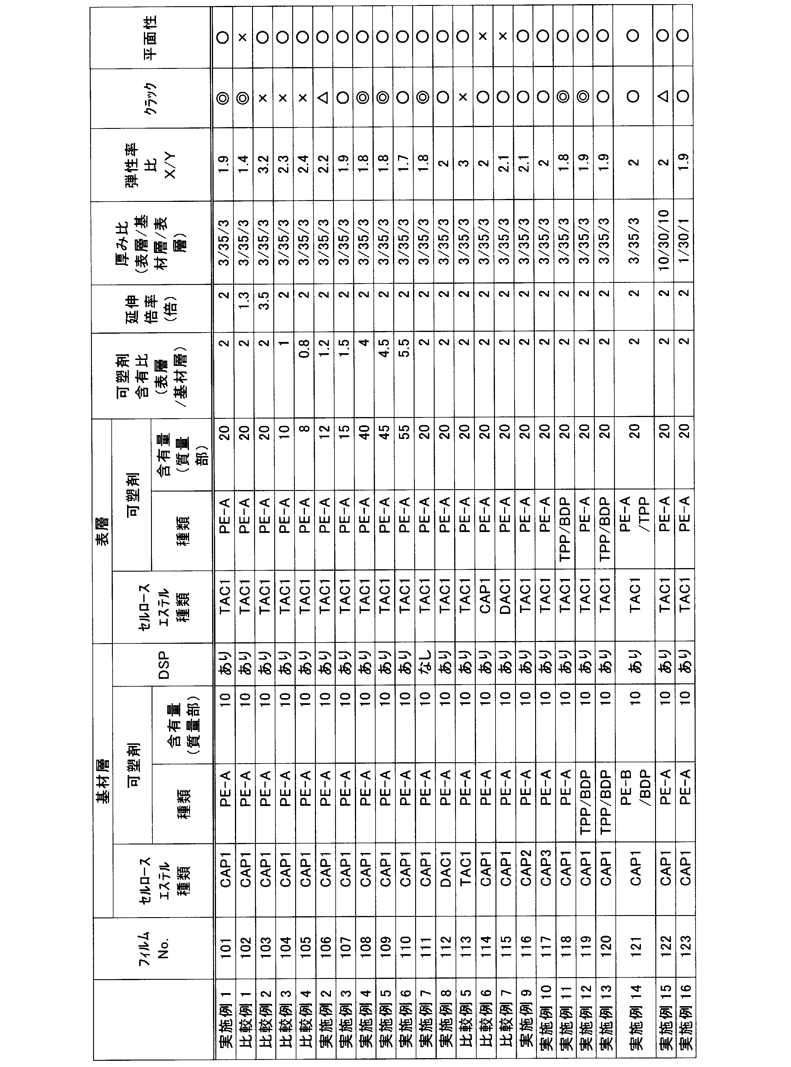

表4および5に示されるように、実施例1~23の光学フィルムは、斜め方向に高倍率で延伸しても表層にクラックが生じないのに対し;比較例2~5の光学フィルムは、クラックが生じることがわかる。
実施例1~24の光学フィルムでクラックが生じなかったのは、表層に含まれる可塑剤量を比較的多くしたことで、表層の引張弾性率が低下したためと考えられる。一方、比較例2の光学フィルムでクラックが生じたのは、斜め方向の延伸倍率が高すぎたためと考えられる。比較例3および4の光学フィルムでクラックが生じたのは、表層の可塑剤量が少ないためと考えられる。比較例5の光学フィルムは、フィルムの引張弾性率が高いことから、クラックが生じたと考えられる。比較例6および7の光学フィルムは、比較例5の光学フィルムよりも、表層におけるセルロースエステルと可塑剤の相溶性が若干劣るため、フィルムの平面性が低下したと考えられる。
また、実施例1の光学フィルムの550nm波長での面内方向のレターデーションRoは135nmであり;厚み方向のレターデーションRthは70nmであった。同様に、実施例2~24の光学フィルムのRoは120~140nmであり、Rthは65~100nmであった。
また、表層を構成するフィルムの引張弾性率と基材層を構成するフィルムの引張弾性率の差(表層と基材層の弾性率差)は、実施例1では0.2GPa;実施例4では-0.4GPa;比較例3では1.3GPaであった。
(実施例25)
偏光子の作製
厚さ120μmの長尺状のポリビニルアルコールフィルムを、延伸温度110℃、延伸倍率5倍の条件で一軸延伸した。得られたフィルムを、ヨウ素0.075g、ヨウ化カリウム5g、水100gからなる水溶液に60秒間浸漬した後、ヨウ化カリウム6g、ホウ酸7.5g、水100gからなる68℃の水溶液に浸漬した。得られたフィルムを、水洗、乾燥して、厚さ20μmの長尺状の偏光子を得た。
偏光子の作製
厚さ120μmの長尺状のポリビニルアルコールフィルムを、延伸温度110℃、延伸倍率5倍の条件で一軸延伸した。得られたフィルムを、ヨウ素0.075g、ヨウ化カリウム5g、水100gからなる水溶液に60秒間浸漬した後、ヨウ化カリウム6g、ホウ酸7.5g、水100gからなる68℃の水溶液に浸漬した。得られたフィルムを、水洗、乾燥して、厚さ20μmの長尺状の偏光子を得た。
円偏光板201の作製
作製した光学フィルム101の、偏光子との貼り合わせ面をアルカリけん化処理した。そして、長尺状の偏光子の一方の面に、光学フィルム101を、接着剤としての完全ケン化型ポリビニルアルコール5%水溶液を介して貼り合わせた。貼り合わせは、偏光子の長手方向と光学フィルムの長手方向とを合わせることで、偏光子の透過軸と光学フィルム101の遅相軸とが45°をなすように行った。
作製した光学フィルム101の、偏光子との貼り合わせ面をアルカリけん化処理した。そして、長尺状の偏光子の一方の面に、光学フィルム101を、接着剤としての完全ケン化型ポリビニルアルコール5%水溶液を介して貼り合わせた。貼り合わせは、偏光子の長手方向と光学フィルムの長手方向とを合わせることで、偏光子の透過軸と光学フィルム101の遅相軸とが45°をなすように行った。
一方、コニカミノルタタックフィルムKC4UA(コニカミノルタオプト(株)製)を準備し、その偏光子との貼り合わせ面をアルカリケン化処理した。そして、偏光子の他方の面に、前述と同様にして、KC4UA(コニカミノルタオプト(株)製)を完全ケン化型ポリビニルアルコール5%水溶液を介して貼り合わせた。それにより、円偏光板201を得た。
有機EL表示装置301の作製
PETフィルム上に、スパッタリング法により、厚さ80nmのクロムからなる金属電極を形成し;この金属電極上に、陽極として厚さ40nmのITOの薄膜を形成した。次いで、この陽極上に、スパッタリング法により、厚さ80nmのポリ(3,4-エチレンジオキシチオフェン)-ポリスチレンスルホネート(PEDOT:PSS)からなる正孔輸送層を形成し;この正孔輸送層上に、シャドーマスクを用いて、RGBの発光層(赤色発光層、緑色発光層および青色発光層)をそれぞれパターニング形成した。発光層の厚みは、各色毎に100nmとした。赤色発光層は、ホストとしてトリス(8-ヒドロキシキノリナート)アルミニウム(Alq3)と発光性化合物[4-(dicyanomethylene)-2-methyl-6(p-dimethylaminostyryl)-4H-pyran](DCM)とを共蒸着(質量比99:1)して形成し;緑色発光層は、ホストとしてAlq3と、発光性化合物クマリン6とを共蒸着(質量比99:1)して形成し;青色発光層は、ホストとしてBAlqと発光性化合物Peryleneとを共蒸着(質量比90:10)して形成した。

PETフィルム上に、スパッタリング法により、厚さ80nmのクロムからなる金属電極を形成し;この金属電極上に、陽極として厚さ40nmのITOの薄膜を形成した。次いで、この陽極上に、スパッタリング法により、厚さ80nmのポリ(3,4-エチレンジオキシチオフェン)-ポリスチレンスルホネート(PEDOT:PSS)からなる正孔輸送層を形成し;この正孔輸送層上に、シャドーマスクを用いて、RGBの発光層(赤色発光層、緑色発光層および青色発光層)をそれぞれパターニング形成した。発光層の厚みは、各色毎に100nmとした。赤色発光層は、ホストとしてトリス(8-ヒドロキシキノリナート)アルミニウム(Alq3)と発光性化合物[4-(dicyanomethylene)-2-methyl-6(p-dimethylaminostyryl)-4H-pyran](DCM)とを共蒸着(質量比99:1)して形成し;緑色発光層は、ホストとしてAlq3と、発光性化合物クマリン6とを共蒸着(質量比99:1)して形成し;青色発光層は、ホストとしてBAlqと発光性化合物Peryleneとを共蒸着(質量比90:10)して形成した。
得られたRGBの発光層上に、真空蒸着法により、電子が効率的に注入できるような仕事関数の低い第1の陰極として、カルシウムからなる厚み4nmの薄膜を形成し;この第1の陰極上に、第2の陰極として厚み2nmのアルミニウムからなる薄膜を形成し、有機発光層を得た。第2の陰極として用いたアルミニウムは、その上に透明電極をスパッタリング法で成膜する際に、第1の陰極であるカルシウムが化学的に変質するのを防ぐ役割がある。
次いで、第2の陰極上に、スパッタリング法により、ITOからなる厚み80nmの透明導電膜(第1の陰極、第2の陰極および透明導電膜を、合わせて透明電極層とする)を形成した。さらに、透明導電膜上に、CVD法により、窒化珪素からなる厚み200nmの薄膜を形成し、絶縁膜(透明基板)とした。それにより、有機EL素子を得た。
得られた有機EL素子の絶縁膜(透明基板)上に、円偏光板201を、接着剤を介して貼り合わせて、有機EL表示装置301を得た。円偏光板201の貼り合わせは、光学フィルム101が、有機EL素子の絶縁膜側となるように行った。
(実施例26~48、比較例10~18)
光学フィルム101を表6に示されるように変更した以外は実施例25と同様にして円偏光板202~233および有機EL表示装置302~333を得た。
光学フィルム101を表6に示されるように変更した以外は実施例25と同様にして円偏光板202~233および有機EL表示装置302~333を得た。
得られた有機EL表示装置の折り曲げ時のシワおよび表示性能を、以下の方法で評価した。
[折り曲げ時の斜め方向のシワ]
得られた有機EL表示装置301を、前述の図1に示されるように、光学フィルムの幅方向(または長尺方向)を折り曲げ軸Cとして、90°に折り曲げ、閉じたり開いたりする操作を10回繰り返した。その後、表示装置の折り曲げ部付近を目視観察して、折り曲げ軸Cに対して斜め方向に生じるシワの有無を、下記の基準で評価した。
◎:斜め方向のシワが全く観察出来ない
○:斜め方向の弱いシワが観察された
△:斜め方向の強いシワが観察された
×:斜め方向の筋状の強いシワが観察された
得られた有機EL表示装置301を、前述の図1に示されるように、光学フィルムの幅方向(または長尺方向)を折り曲げ軸Cとして、90°に折り曲げ、閉じたり開いたりする操作を10回繰り返した。その後、表示装置の折り曲げ部付近を目視観察して、折り曲げ軸Cに対して斜め方向に生じるシワの有無を、下記の基準で評価した。
◎:斜め方向のシワが全く観察出来ない
○:斜め方向の弱いシワが観察された
△:斜め方向の強いシワが観察された
×:斜め方向の筋状の強いシワが観察された
[表示性能]
得られた有機EL表示装置301を、発光させた状態で目視観察し、画面における外光反射の有無を、以下の基準で評価した。
◎:全く外光反射が認知出来ない
○:僅かに外光反射による赤味が見られるが、気にならない程度
△:外光反射による赤味が気になる状態
×:外光反射による赤味が極めて気になる状態。
得られた有機EL表示装置301を、発光させた状態で目視観察し、画面における外光反射の有無を、以下の基準で評価した。
◎:全く外光反射が認知出来ない
○:僅かに外光反射による赤味が見られるが、気にならない程度
△:外光反射による赤味が気になる状態
×:外光反射による赤味が極めて気になる状態。
実施例25~48および比較例10~18の有機EL表示装置の評価結果を表6に示す。
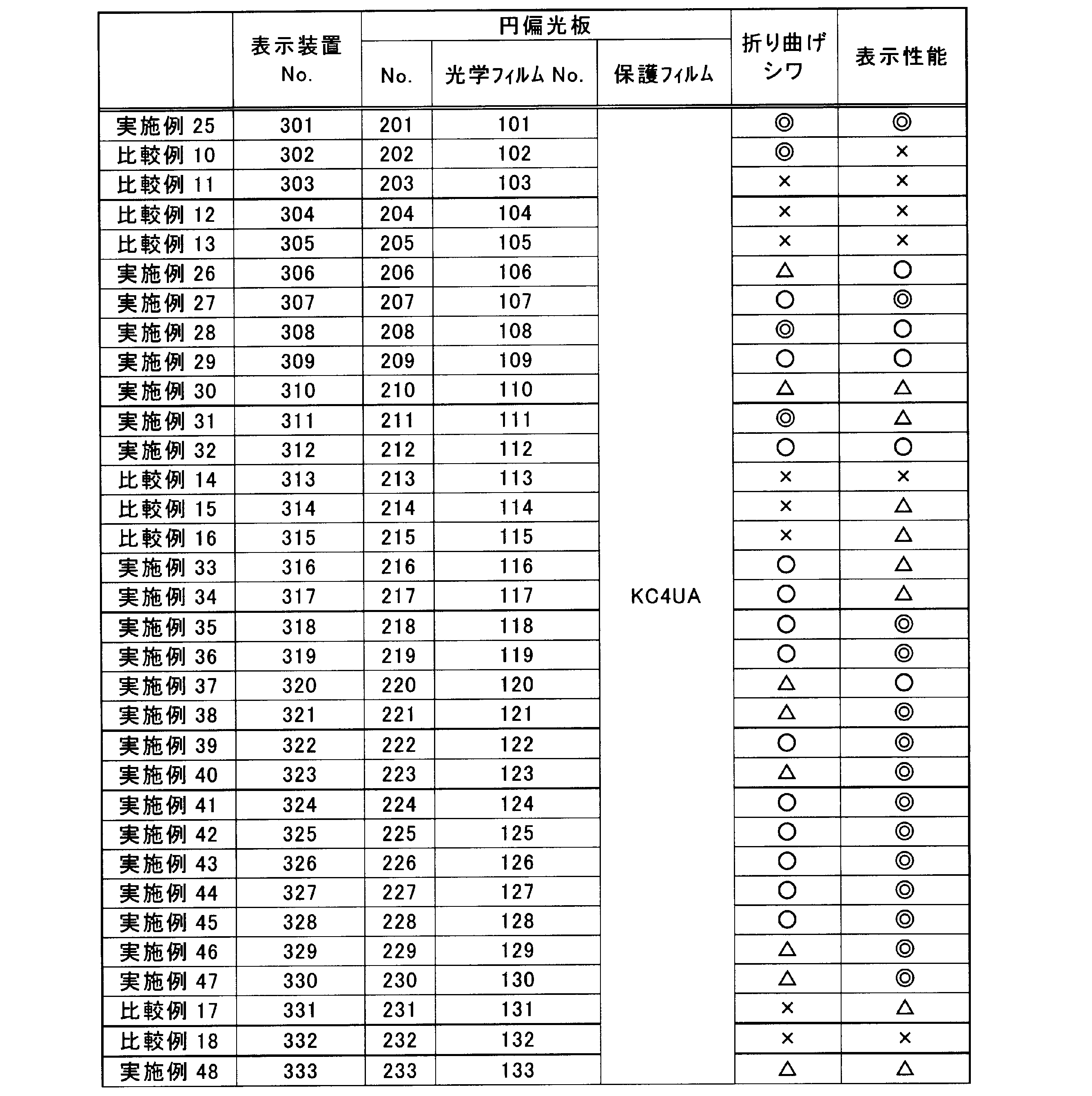
表6に示されるように、実施例25~48の有機EL表示装置は、折り曲げ時の斜め方向のシワがほとんど生じず、表示性能が良好であるのに対し;比較例11~18の有機EL表示装置は、少なくとも折り曲げ時の斜め方向のシワが生じ、表示性能も低いことがわかる。
比較例10では、光学フィルム102の延伸倍率が低く、所望の位相差を有しないことから、有機EL表示装置の表示性能が低いと考えられる。比較例11~13では、前述の通り、光学フィルムの各層の引張弾性率差が大きいことから、折り曲げ時の斜め方向のシワが生じることがわかる。
比較例14~16の表示装置は、いずれも表示性能が低いことがわかる。これは、比較例15に用いられる光学フィルムの表層の主成分がCAPであり;比較例16に用いられる光学フィルムの表層の主成分がDACであるため、いずれもアルカリ水溶液による鹸化処理により、フィルム表面が破壊されたためと考えられる。
また、実施例25、48および比較例17~18の対比から、「表層の可塑剤量/基材層の可塑剤量の比が一定以上」であり、かつ「表層の可塑剤量が一定以上」とすることで、表示装置の折り曲げ時のシワや表示特性を高めることができることがわかる。
本出願は、2012年12月14日出願の特願2012-273508に基づく優先権を主張する。当該出願明細書および図面に記載された内容は、すべて本願明細書に援用される。
本発明によれば、厚みが薄くても、加工時に裂けにくい光学フィルムを提供することができる。
1、10、73 光学フィルム
C 折り曲げ軸
11、73-1 基材層
13、13’、73-3、73-3’ 表層
15 引張試験機
20 斜め延伸機
21 フィルム繰り出し装置
23 搬送方向変更装置
25 巻き取り装置
30 有機EL表示装置
50 有機EL素子
51 基板
53 金属電極
55 TFT
57 有機発光層
59 透明電極(ITO等)
61 絶縁層
63 封止層
65 フィルム
70 円偏光板
71 偏光子
75 保護フィルム
S1、S2 サンプルフィルム
C 折り曲げ軸
11、73-1 基材層
13、13’、73-3、73-3’ 表層
15 引張試験機
20 斜め延伸機
21 フィルム繰り出し装置
23 搬送方向変更装置
25 巻き取り装置
30 有機EL表示装置
50 有機EL素子
51 基板
53 金属電極
55 TFT
57 有機発光層
59 透明電極(ITO等)
61 絶縁層
63 封止層
65 フィルム
70 円偏光板
71 偏光子
75 保護フィルム
S1、S2 サンプルフィルム
Claims (15)
- セルロースアセテートプロピオネートまたはアセチル基の置換度が2.0以上2.6以下のセルロースアセテートと可塑剤とを含有する基材層と、前記基材層の両面に配置され、アセチル基の置換度が2.6超3.0以下のセルロースアセテートと可塑剤とを含有する表層とを含む、有機EL表示装置用の光学フィルムであって、
前記光学フィルムの面内の遅相軸方向が、フィルムの幅方向に対して斜め方向であり、
前記遅相軸方向の引張弾性率Xの、前記遅相軸方向と直交する方向の引張弾性率Yに対する比X/Yが1.5以上5.0以下であり、
前記表層に含まれる可塑剤の量の前記基材層に含まれる可塑剤の量に対する質量比が、1.2倍以上5.5倍以下である、光学フィルム。 - 前記光学フィルムの面内の遅相軸方向が、フィルムの幅方向に対して40~50°の範囲である、請求項1に記載の光学フィルム。
- 前記基材層が、波長分散調整剤をさらに含有する、請求項1に記載の光学フィルム。
- 前記表層に含まれる可塑剤の量が、前記表層に含まれる前記アセチル基の置換度が2.6超3.0以下のセルロースアセテートに対して15~50質量%である、請求項1に記載の光学フィルム。
- 前記基材層に含まれる前記セルロースアセテートプロピオネートまたは前記アセチル基の置換度が2.0以上2.6以下のセルロースアセテートの重量平均分子量Mwが15万~30万であり、かつ数平均分子量Mnが5万~20万である、請求項1に記載の光学フィルム。
- 前記表層に含まれる可塑剤が、ジオールとジカルボン酸とを重縮合反応させて得られるポリエステル化合物である、請求項1に記載の光学フィルム。
- 前記ポリエステル化合物の重量平均分子量が700~2000である、請求項6に記載の光学フィルム。
- 前記ポリエステル化合物の分子末端は、水酸基であるか、アセチル基で封止されている、請求項6に記載の光学フィルム。
- 前記ポリエステル化合物を構成する前記ジカルボン酸が、芳香族ジカルボン酸と、脂肪族ジカルボン酸とを含有する、請求項6に記載の光学フィルム。
- 前記光学フィルムの、式(I)で定義され、波長550nmにおける面内方向のレターデーションRoが120~180nmの範囲内であり、式(II)で定義され、波長550nmにおける厚み方向のレターデーションRthが40~120nmである、請求項1に記載の光学フィルム。
式(I) Ro=(nx-ny)×d
式(II) Rth={(nx+ny)/2-nz}×d
(nx:フィルム面内の遅相軸方向xの屈折率、ny:フィルム面内において、遅相軸方向xに対して直交する方向yの屈折率、nz:フィルムの厚み方向zの屈折率、d:フィルムの厚み(nm)) - 請求項1に記載の光学フィルムを含む、円偏光板。
- 請求項1に記載の光学フィルムを含む、有機EL表示装置。
- 請求項1に記載の光学フィルムの製造方法であって、
セルロースアセテートプロピオネートまたはアセチル基の置換度が2.0以上2.6以下のセルロースアセテートと可塑剤とを含有する第一の層と、前記第一の層の両面に配置され、アセチル基の置換度が2.6超3.0以下のセルロースアセテートと可塑剤とを含有する第二の層とを含む積層フィルムを得る工程と、
前記積層フィルムを、少なくとも前記積層フィルムの幅方向に対して斜め方向に1.5倍以上3.0倍以下の倍率で延伸して光学フィルムを得る工程と、を含む、光学フィルムの製造方法。 - 前記積層フィルムを得る工程は、
セルロースアセテートプロピオネートまたはアセチル基の置換度が2.0以上2.6以下のセルロースアセテート、可塑剤および有機溶媒を含有する第一の層用ドープと、アセチル基の置換度が2.6超3.0以下のセルロースアセテート、可塑剤および有機溶媒を含有する第二の層用ドープとを得る工程と、
前記第一の層用ドープと前記第二の層用ドープとを、流延支持体上に同時または逐次に積層しながら流延する工程と、
前記積層された前記第一の層用ドープと前記第二の層用ドープに含まれる有機溶媒を除去して、積層フィルムを得る工程とを含む、請求項13に記載の光学フィルムの製造方法。 - 前記積層フィルムの延伸は、フィルムの幅方向に対して40~50°の方向に行う、請求項13に記載の光学フィルムの製造方法。
Priority Applications (1)
| Application Number | Priority Date | Filing Date | Title |
|---|---|---|---|
| JP2014551895A JPWO2014091759A1 (ja) | 2012-12-14 | 2013-12-11 | 光学フィルムとその製造方法、円偏光板および有機el表示装置 |
Applications Claiming Priority (2)
| Application Number | Priority Date | Filing Date | Title |
|---|---|---|---|
| JP2012-273508 | 2012-12-14 | ||
| JP2012273508 | 2012-12-14 |
Publications (1)
| Publication Number | Publication Date |
|---|---|
| WO2014091759A1 true WO2014091759A1 (ja) | 2014-06-19 |
Family
ID=50934066
Family Applications (1)
| Application Number | Title | Priority Date | Filing Date |
|---|---|---|---|
| PCT/JP2013/007300 Ceased WO2014091759A1 (ja) | 2012-12-14 | 2013-12-11 | 光学フィルムとその製造方法、円偏光板および有機el表示装置 |
Country Status (2)
| Country | Link |
|---|---|
| JP (1) | JPWO2014091759A1 (ja) |
| WO (1) | WO2014091759A1 (ja) |
Cited By (6)
| Publication number | Priority date | Publication date | Assignee | Title |
|---|---|---|---|---|
| JP2017009713A (ja) * | 2015-06-18 | 2017-01-12 | 富士フイルム株式会社 | 偏光板及び液晶表示装置 |
| JP2017207596A (ja) * | 2016-05-17 | 2017-11-24 | 日東電工株式会社 | 光学積層体 |
| JP2018151425A (ja) * | 2017-03-09 | 2018-09-27 | 昭和電工株式会社 | 光制御パネルおよび光学結像装置ならびに光制御パネルの製造方法 |
| JP2018168306A (ja) * | 2017-03-30 | 2018-11-01 | 東ソー株式会社 | 樹脂溶液およびそれを用いた光学フィルムの製造方法 |
| CN110249376A (zh) * | 2017-01-06 | 2019-09-17 | 大日本印刷株式会社 | 光学膜和图像显示装置 |
| WO2020121708A1 (ja) * | 2018-12-10 | 2020-06-18 | 日本ゼオン株式会社 | 積層体及びその製造方法、円偏光板、表示装置並びにタッチパネル |
Citations (8)
| Publication number | Priority date | Publication date | Assignee | Title |
|---|---|---|---|---|
| JPH08207210A (ja) * | 1995-02-03 | 1996-08-13 | Fuji Photo Film Co Ltd | セルロースアセテート積層フイルムおよびその製造方法 |
| JP2002131542A (ja) * | 2000-10-24 | 2002-05-09 | Fuji Photo Film Co Ltd | 位相差板、円偏光板、及び位相差板の製造方法 |
| JP2006083357A (ja) * | 2004-09-17 | 2006-03-30 | Fuji Photo Film Co Ltd | セルロースアシレートフイルム、光学補償フイルム、偏光板および液晶表示装置 |
| JP2006199855A (ja) * | 2005-01-21 | 2006-08-03 | Fuji Photo Film Co Ltd | 高分子フィルム、光学補償フィルム、これらの製造方法、偏光板および液晶表示装置 |
| JP2006291186A (ja) * | 2005-03-14 | 2006-10-26 | Fuji Photo Film Co Ltd | セルロースアシレートフィルム及びその製造方法、光学補償フィルム、偏光板および液晶表示装置 |
| WO2009107407A1 (ja) * | 2008-02-26 | 2009-09-03 | コニカミノルタオプト株式会社 | 位相差フィルム、偏光板および液晶表示装置 |
| JP2012066571A (ja) * | 2010-08-25 | 2012-04-05 | Fujifilm Corp | セルロースアシレートフィルムおよびその製造方法、偏光板および液晶表示装置 |
| JP2012215688A (ja) * | 2011-03-31 | 2012-11-08 | Fujifilm Corp | 光学フィルムとその製造方法、偏光板および液晶表示装置 |
-
2013
- 2013-12-11 WO PCT/JP2013/007300 patent/WO2014091759A1/ja not_active Ceased
- 2013-12-11 JP JP2014551895A patent/JPWO2014091759A1/ja active Pending
Patent Citations (8)
| Publication number | Priority date | Publication date | Assignee | Title |
|---|---|---|---|---|
| JPH08207210A (ja) * | 1995-02-03 | 1996-08-13 | Fuji Photo Film Co Ltd | セルロースアセテート積層フイルムおよびその製造方法 |
| JP2002131542A (ja) * | 2000-10-24 | 2002-05-09 | Fuji Photo Film Co Ltd | 位相差板、円偏光板、及び位相差板の製造方法 |
| JP2006083357A (ja) * | 2004-09-17 | 2006-03-30 | Fuji Photo Film Co Ltd | セルロースアシレートフイルム、光学補償フイルム、偏光板および液晶表示装置 |
| JP2006199855A (ja) * | 2005-01-21 | 2006-08-03 | Fuji Photo Film Co Ltd | 高分子フィルム、光学補償フィルム、これらの製造方法、偏光板および液晶表示装置 |
| JP2006291186A (ja) * | 2005-03-14 | 2006-10-26 | Fuji Photo Film Co Ltd | セルロースアシレートフィルム及びその製造方法、光学補償フィルム、偏光板および液晶表示装置 |
| WO2009107407A1 (ja) * | 2008-02-26 | 2009-09-03 | コニカミノルタオプト株式会社 | 位相差フィルム、偏光板および液晶表示装置 |
| JP2012066571A (ja) * | 2010-08-25 | 2012-04-05 | Fujifilm Corp | セルロースアシレートフィルムおよびその製造方法、偏光板および液晶表示装置 |
| JP2012215688A (ja) * | 2011-03-31 | 2012-11-08 | Fujifilm Corp | 光学フィルムとその製造方法、偏光板および液晶表示装置 |
Cited By (11)
| Publication number | Priority date | Publication date | Assignee | Title |
|---|---|---|---|---|
| JP2017009713A (ja) * | 2015-06-18 | 2017-01-12 | 富士フイルム株式会社 | 偏光板及び液晶表示装置 |
| JP2017207596A (ja) * | 2016-05-17 | 2017-11-24 | 日東電工株式会社 | 光学積層体 |
| CN110249376A (zh) * | 2017-01-06 | 2019-09-17 | 大日本印刷株式会社 | 光学膜和图像显示装置 |
| CN110249376B (zh) * | 2017-01-06 | 2021-08-24 | 大日本印刷株式会社 | 光学膜和图像显示装置 |
| JP2018151425A (ja) * | 2017-03-09 | 2018-09-27 | 昭和電工株式会社 | 光制御パネルおよび光学結像装置ならびに光制御パネルの製造方法 |
| JP2018168306A (ja) * | 2017-03-30 | 2018-11-01 | 東ソー株式会社 | 樹脂溶液およびそれを用いた光学フィルムの製造方法 |
| WO2020121708A1 (ja) * | 2018-12-10 | 2020-06-18 | 日本ゼオン株式会社 | 積層体及びその製造方法、円偏光板、表示装置並びにタッチパネル |
| CN112996657A (zh) * | 2018-12-10 | 2021-06-18 | 日本瑞翁株式会社 | 层叠体及其制造方法、圆偏振片、显示装置以及触控面板 |
| JPWO2020121708A1 (ja) * | 2018-12-10 | 2021-11-04 | 日本ゼオン株式会社 | 積層体及びその製造方法、円偏光板、表示装置並びにタッチパネル |
| JP7355036B2 (ja) | 2018-12-10 | 2023-10-03 | 日本ゼオン株式会社 | 積層体及びその製造方法、円偏光板、表示装置並びにタッチパネル |
| TWI829817B (zh) * | 2018-12-10 | 2024-01-21 | 日商日本瑞翁股份有限公司 | 堆疊體及其製造方法、圓偏光板、顯示裝置以及觸控面板 |
Also Published As
| Publication number | Publication date |
|---|---|
| JPWO2014091759A1 (ja) | 2017-01-05 |
Similar Documents
| Publication | Publication Date | Title |
|---|---|---|
| JP6623737B2 (ja) | 光学フィルムの製造方法および製造装置 | |
| CN104903406B (zh) | 树脂组合物、三唑化合物、光学膜、偏振片、光学透镜、圆偏振片及图像显示装置 | |
| JP6935840B2 (ja) | 斜め延伸フィルムの製造方法 | |
| WO2014091759A1 (ja) | 光学フィルムとその製造方法、円偏光板および有機el表示装置 | |
| JP6123676B2 (ja) | 円偏光板を具備する有機エレクトロルミネッセンス表示装置 | |
| JP6299224B2 (ja) | 有機エレクトロルミネッセンス表示装置 | |
| JP6923048B2 (ja) | 斜め延伸フィルムの製造方法 | |
| KR101677866B1 (ko) | 위상차 필름, 원편광판 및 화상 표시 장치 | |
| WO2014061215A1 (ja) | 位相差フィルム、該位相差フィルムを用いて作製した円偏光板および有機elディスプレイ | |
| TW201711828A (zh) | 斜面延伸薄膜之製造方法 | |
| JP6102738B2 (ja) | 有機エレクトロルミネッセンス表示装置、円偏光板の製造方法及び長尺状のλ/4板 | |
| WO2014049954A1 (ja) | 位相差フィルム、該位相差フィルムを用いて作製した長尺円偏光板および有機elディスプレイ | |
| KR101662920B1 (ko) | λ/4 위상차 필름과 그의 제조 방법, 원 편광판 및 유기 일렉트로루미네센스 표시 장치 | |
| JP6048349B2 (ja) | 位相差フィルムの製造方法 | |
| JP6136929B2 (ja) | 有機エレクトロルミネッセンス画像表示装置 | |
| JP5724847B2 (ja) | 有機エレクトロルミネッセンス立体画像表示システム | |
| WO2013137123A1 (ja) | λ/4位相差フィルム、円偏光板及び有機エレクトロルミネッセンス表示装置 | |
| WO2013137058A1 (ja) | λ/4位相差フィルム及び有機エレクトロルミネッセンス画像表示装置 | |
| JP5970781B2 (ja) | 有機エレクトロルミネッセンス表示装置 | |
| WO2014087593A1 (ja) | 位相差フィルム、円偏光板、及び画像表示装置 | |
| WO2016132893A1 (ja) | 長尺斜め延伸フィルムの製造方法 | |
| JP2016018021A (ja) | 円偏光板、有機エレクトロルミネッセンス表示装置及び円偏光板の製造方法 |
Legal Events
| Date | Code | Title | Description |
|---|---|---|---|
| 121 | Ep: the epo has been informed by wipo that ep was designated in this application |
Ref document number: 13862775 Country of ref document: EP Kind code of ref document: A1 |
|
| ENP | Entry into the national phase |
Ref document number: 2014551895 Country of ref document: JP Kind code of ref document: A |
|
| NENP | Non-entry into the national phase |
Ref country code: DE |
|
| 122 | Ep: pct application non-entry in european phase |
Ref document number: 13862775 Country of ref document: EP Kind code of ref document: A1 |