WO2014087476A1 - 電子部品装着機 - Google Patents
電子部品装着機 Download PDFInfo
- Publication number
- WO2014087476A1 WO2014087476A1 PCT/JP2012/081336 JP2012081336W WO2014087476A1 WO 2014087476 A1 WO2014087476 A1 WO 2014087476A1 JP 2012081336 W JP2012081336 W JP 2012081336W WO 2014087476 A1 WO2014087476 A1 WO 2014087476A1
- Authority
- WO
- WIPO (PCT)
- Prior art keywords
- electronic component
- mounting machine
- electronic components
- electronic
- mounting
- Prior art date
- Legal status (The legal status is an assumption and is not a legal conclusion. Google has not performed a legal analysis and makes no representation as to the accuracy of the status listed.)
- Ceased
Links
Images






Classifications
-
- H—ELECTRICITY
- H05—ELECTRIC TECHNIQUES NOT OTHERWISE PROVIDED FOR
- H05K—PRINTED CIRCUITS; CASINGS OR CONSTRUCTIONAL DETAILS OF ELECTRIC APPARATUS; MANUFACTURE OF ASSEMBLAGES OF ELECTRICAL COMPONENTS
- H05K13/00—Apparatus or processes specially adapted for manufacturing or adjusting assemblages of electric components
- H05K13/04—Mounting of components, e.g. of leadless components
- H05K13/0404—Pick-and-place heads or apparatus, e.g. with jaws
-
- H—ELECTRICITY
- H05—ELECTRIC TECHNIQUES NOT OTHERWISE PROVIDED FOR
- H05K—PRINTED CIRCUITS; CASINGS OR CONSTRUCTIONAL DETAILS OF ELECTRIC APPARATUS; MANUFACTURE OF ASSEMBLAGES OF ELECTRICAL COMPONENTS
- H05K13/00—Apparatus or processes specially adapted for manufacturing or adjusting assemblages of electric components
- H05K13/08—Monitoring manufacture of assemblages
- H05K13/0895—Maintenance systems or processes, e.g. indicating need for maintenance
Definitions
- the present invention relates to an electronic component mounting machine including a holder for holding an electronic component to be mounted on a circuit board, and a detachable component storage unit for storing an electronic component detached from the holder.
- the electronic components are held by a holder, and the electronic components are mounted on the circuit board.
- the mounting component held by the holder may be a defective product. In such a case, it is necessary to discard the mounting component. For this reason, as described in Patent Document 1 below, a component storage unit such as a disposal box is provided in the work machine, and the holder releases the electronic component above the component storage unit. The electronic component is discarded in the component storage unit.
- the electronic component is intentionally detached from the holder, but the electronic component may be unexpectedly detached from the holder. That is, the electronic component may fall from the holder. As described above, when the electronic component is unexpectedly detached from the holder, the electronic component may fall on the circuit board. For this reason, in the electronic component mounting machine described in Patent Document 2 below, a component housing portion is disposed below the holder. Thereby, the electronic component dropped from the holder is accommodated in the component accommodating portion, and the electronic component is prevented from dropping onto the circuit board.
- the electronic component mounting machine described in the above-mentioned patent document it becomes possible to dispose of poor electronic components and the like suitably. Further, it is possible to suitably prevent the electronic component that has unexpectedly detached from the holder from falling onto the circuit board.
- the component accommodating portion for accommodating discarded components and the component accommodating portion for accommodating dropped electronic components are generally small and cannot accommodate a large amount of components. For this reason, it is necessary for an operator to collect the electronic component from the component housing portion. However, it is a wasteful work to collect the electronic components from the component housing portion that is in an almost empty state. On the other hand, when many electronic components are discarded or dropped in the component housing portion, there is a possibility that the electronic components overflow from the component housing portion.
- This invention is made
- an electronic component mounting machine accommodates a holder for holding an electronic component mounted on a circuit board and an electronic component detached from the holder.
- An electronic component mounting machine including a detached component storage unit, wherein the number of electronic components stored in the detached component storage unit is acquired, and the electronic component acquired by the stored number acquisition unit And a recovery timing determining unit that determines a recovery timing for recovering the electronic component from the detached component accommodating unit based on the number and a preset threshold number set in advance.
- the electronic component mounting machine includes a waste component storage portion that stores the electronic component discarded by the holder, and the waste component storage portion.
- the electronic component discarded by the holder is accommodated as an electronic component detached from the holder, thereby functioning as the detached component accommodating portion.
- an electronic component mounting machine stores a plurality of electronic components in a state of being separated and an electronic component stored in the storage portion. And a supply passage that leads the electronic component to a supply position in a line, and a bulk feeder that supplies the electronic component at the supply position; a mounting head that has the holder; and The bulk feeder and the waste component storage unit are fixedly connected to the mounting head, and can be moved to an arbitrary position by the moving device together with the mounting head. It is characterized by that.
- the ratio of the volume of the storage unit to the number of electronic components that can be stored in the storage unit by the control device in the electronic component mounting machine according to claim 4, the ratio of the volume of the storage unit to the number of electronic components that can be stored in the storage unit by the control device. And a set threshold number determining unit that determines the set threshold number based on the volume of the waste component storage unit.
- the collection timing determination unit is an electronic device discarded at the time of mounting work on one circuit board.
- the collection timing determination unit is acquired by the accommodation number acquisition unit at the end of the mounting operation on one circuit board. Even if the total number of electronic components to be acquired and the number of electronic components acquired by the discarded component number acquisition unit exceeds the set threshold number, circuit boards subsequent to that one circuit board When the electronic component is replenished to the storage unit during the mounting operation, the supply timing of the electronic component to the storage unit is determined as the collection timing.
- the electronic component mounting machine is the electronic component mounting machine according to claim 1, wherein the electronic component mounting machine is provided below the mounting tool and a mounting head that holds the holding tool, and falls from the holding tool.
- the stacking mechanism causes the electronic component dropped on the receiving portion to pass through a hole formed in the receiving portion. It is characterized by accumulating toward.
- the mounting head holds the plurality of holders in an annular shape. It is characterized by doing.
- the receiving surface on which the stacking mechanism receives the electronic component of the receiving portion is swept up by the cleaning member.
- the mounting head detachably holds the holder and the cleaning member can also be detached. It is characterized by holding.
- the cleaning member is fixed to the mounting head so as to be movable in the vertical direction.
- An electronic component mounting machine is the electronic component mounting machine according to any one of claims 10 to 12, wherein the mounting head is disposed above the receiving portion. And an image pickup device that picks up an image of an electronic component held by the holder, and a lens cleaner for wiping a lens of the image pickup device, and the lens cleaner is fixed to the cleaning member. And the lens is wiped by the operation of the accumulating mechanism.
- the cleaning member is a cleaning brush in which a plurality of hairs are bundled, and the lens cleaner is the plurality of lens cleaners. It is attached to the upper part of the said cleaning brush integrally with the hair of No ..
- the plurality of hairs are bundled in a cylindrical shape, and the lens cleaner is bundled in a cylindrical shape. It was attached to the outer peripheral part of several hair.
- the imaging device in the electronic component mounting machine according to claim 16, in the electronic component mounting machine according to claim 14 or 15, the imaging device includes a lens support base that supports the lens, and the lens support base Has a taper surface for scraping the plurality of hairs.
- the stacking mechanism has a rod-shaped holding member that holds the cleaning member at a lower end portion thereof, and holds the holding member.
- the member has a bent portion bent in a crank shape, and holds the lens cleaner at an upper end portion of the bent portion.
- An electronic component mounting machine is the electronic component mounting machine according to any one of claims 7 to 17, wherein a storage unit that stores a plurality of electronic components in a loose state; A supply passage that leads the electronic components stored in the storage unit to the electronic component supply position in a state of being aligned in a row, and a bulk feeder that supplies the electronic components at the supply position; The bulk feeder is fixedly connected to the mounting head, and can be moved to an arbitrary position by the moving device together with the mounting head.
- the collection timing of the electronic component from the detached component accommodating portion is based on the number of electronic components accommodated in the detached component accommodating portion and a preset threshold number. It is determined. Thereby, it becomes possible to collect the electronic component from the detached component accommodating portion at a suitable timing.
- the set threshold number is desirably set to the number of electronic components that can be accommodated in the detached component accommodating portion.
- the detached component accommodating portion is limited to the discarded component accommodating portion that accommodates the electronic component discarded by the holder. Thereby, it becomes possible to collect the discarded parts at a suitable timing.
- the bulk feeder and the waste component storage unit are fixedly connected to the mounting head. This makes it possible to shorten the movement time of the mounting head when the holder holds the electronic component from the bulk feeder and when the electronic component held by the holder is discarded in the waste component storage unit. Become. Therefore, according to the electronic component mounting machine of the third aspect, efficient mounting work and disposal work can be performed.
- the set threshold number is based on the ratio of the volume of the storage unit to the number of electronic components that can be stored in the storage unit of the bulk feeder and the volume of the waste component storage unit. Is determined. It is desirable to set the set threshold number to the number of electronic components that can be accommodated in the waste component accommodating portion. However, since there is a gap between a plurality of electronic components housed in the waste component housing part, it is not possible to appropriately set the number of waste parts that can be housed in the waste part housing part, that is, the set threshold number. Have difficulty. However, if the volume required for one electronic component in the waste component storage unit can be estimated appropriately, the set threshold number can be set appropriately.
- the electronic component discarded in the discarded component storage unit is the same as the electronic component stored in the storage unit of the bulk feeder. Further, the ratio of the volume of the storage unit to the number of electronic components that can be stored in the storage unit of the bulk feeder is an average value of the volume required for one electronic component in the storage unit. For this reason, the ratio can be considered as an average value of the volume required for one electronic component in the discarded component storage unit. In other words, by setting the value obtained by dividing the volume of the waste component storage unit by the above ratio as the set threshold number, the set threshold number is set to a value that approximates the number of electronic components that can be stored in the waste component storage unit.
- the number of electronic components accommodated in the discarded component accommodating portion at the end of the mounting operation, and the number of electronic components discarded during the mounting operation on one circuit board is determined as the collection timing. That is, it is determined whether or not the waste component overflows from the waste component storage portion during the mounting operation on the next circuit board. And when it determines with overflowing, the time of replacement
- the operator can suppress a decrease in throughput associated with the recovery operation of the waste components by performing the recovery operation of the waste components using the replacement time of the circuit board.
- the electronic component to the bulk feeder is mounted during the subsequent mounting operation on the circuit board.
- the electronic component replenishment time is determined as the collection timing.
- the detached component accommodating portion is limited to the receiving portion that accommodates the electronic component dropped from the holder.
- a collection timing is determined based on the number of dropped electronic components and the set threshold number, and the electronic components accommodated in the receiving unit are accumulated by the accumulation mechanism at that timing. That is, when the number of electronic components accommodated in the receiving unit reaches a predetermined number, the electronic components accommodated in the receiving unit are automatically accumulated. As a result, it is possible to accumulate the electronic components accommodated in the receiving unit at a suitable timing to form a new space. In addition, the work can be automatically performed.
- the through hole is formed in the receiving portion, and the electronic components accommodated in the receiving portion are integrated toward the through hole. That is, by moving the receiving unit onto the disposal box and dropping the electronic component from the through hole, the electronic component accommodated in the receiving unit is discarded in the disposal box. This makes it possible to remove the electronic component from the receiving unit at an appropriate timing and to automate the removal operation of the electronic component.
- the plurality of holders are held by the mounting head in a state of being arranged in an annular shape. As the number of holders increases, the number of electronic components falling from the holders also increases. For this reason, in the electronic component mounting machine according to the ninth aspect, the effect of automatically removing the electronic component from the receiving portion is fully utilized.
- the electronic components dropped on the receiving unit are swept up by the cleaning member that moves along the receiving surface of the receiving unit.
- the electronic components accommodated in the receiving unit can be appropriately integrated.
- the holder and the cleaning member are detachably mounted on the mounting head.
- the holder can be mounted on the mounting head during the mounting operation
- the cleaning member can be mounted on the mounting head during the cleaning operation.
- the cleaning member is fixed to the mounting head so as to be movable in the vertical direction. Thereby, the cleaning member can be moved downward during the cleaning operation, and the cleaning member can be moved upward during the mounting operation.
- the lens cleaner is fixedly connected to the cleaning member. And the lens of the imaging device fixedly connected with the mounting head is cleaned by the lens cleaner by the accumulation mechanism operating the cleaning member. This makes it possible to automatically clean the lens as well as the receiving portion.
- the cleaning brush in which a plurality of hairs are bundled functions as a cleaning member, and the lens cleaner is integrated with the plurality of hairs of the brush on the upper part of the cleaning brush. Is attached. Thereby, the structure of the cleaning member having the cleaning brush and the lens cleaner can be simplified.
- the plurality of hairs of the cleaning brush are bundled in a cylindrical shape, and the lens cleaner is attached to the outer peripheral portion of the cylindrical cleaning brush.
- the cleaning member has a generally cylindrical shape, and the directionality of the work can be eliminated.
- the electronic component mounting machine is provided with a lens support base for supporting the lens of the imaging device, and the lens support base has a tape support for scraping the hair of the cleaning brush.
- a flat surface is formed.
- the hair of the cleaning brush is relatively hard, and the contact between the hair of the cleaning brush and the lens is not preferable. For this reason, the hair of the cleaning brush is separated from the side of the lens by the taper surface of the lens support, thereby preventing the cleaning brush from contacting the lens.
- the cleaning member is held at the lower end portion of the rod-like holding member, and the holding member is formed with a bent portion bent in a crank shape.
- a lens cleaner is attached to the upper end of the bent portion. For this reason, when the lens is cleaned by the lens cleaner, the imaging device is positioned between both ends of the portion of the holding member bent in a crank shape. Accordingly, it is possible to perform the lens cleaning operation while avoiding contact between the manufacturing member and the imaging device.
- the electronic component mounting machine in the electronic component mounting machine according to claim 18, it is fixedly connected to the bulk feeder mounting head. Thereby, when the holder holds the electronic component from the bulk feeder, it is possible to reduce the movement time of the mounting head. Therefore, according to the electronic component mounting machine of the eighteenth aspect, it is possible to perform an efficient mounting operation.
- FIG. 5 shows the receiving tray shown in FIG. 5 in the viewpoint from upper direction.
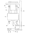
- a side view shows a 2nd parts camera (3rd parts camera) attached to the mounting head and its mounting head.
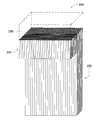
- FIG. 1 It is a perspective view which shows a bulk feeder. It is a side view which shows a bulk feeder. It is sectional drawing in the AA line shown in FIG. It is sectional drawing in the BB line shown in FIG. It is a side view showing a mounting head in a state where a cleaning tool is mounted on the mounting unit. It is a block diagram which shows the control apparatus with which an electronic component mounting machine is provided. It is a figure which shows the relationship between the replacement timing of a circuit board, the number of electronic components discarded in a 1st disposal box, and the collection timing of the electronic components from a 1st disposal box.
- the figure which shows the relationship between the replenishment timing of the electronic component to a bulk feeder, the replacement timing of a circuit board, the number of electronic components discarded to a 1st disposal box, and the collection timing of the electronic component from a 1st disposal box. is there. It is a perspective view which shows the cleaning tool of the modification 1. It is a side view which shows the mounting head of the state with which the cleaning tool of the modification 1 was mounted
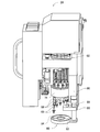
- FIG. 1 shows an electronic component mounting apparatus (hereinafter sometimes abbreviated as “mounting apparatus”) 10.
- the figure is a perspective view in which a part of the exterior component of the mounting apparatus 10 has been removed.
- the mounting apparatus 10 includes one system base 12 and two electronic component mounting machines (hereinafter, may be abbreviated as “mounting machines”) 16. These two mounting machines 16 are arranged side by side on the system base 12 and perform an operation of mounting electronic components on the circuit board.
- the direction in which the mounting machines 16 are arranged is referred to as an X-axis direction
- a horizontal direction perpendicular to the direction is referred to as a Y-axis direction.
- Each of the mounting machines 16 mainly includes a mounting machine main body 20, a transport device 22, a mounting head moving device (hereinafter sometimes abbreviated as “moving device”) 24, a supply device 26, and a mounting head 28.
- the mounting machine main body 20 includes a frame portion 30 and a beam portion 32 that is overlaid on the frame portion 30.
- the transport device 22 includes two conveyor devices 40 and 42.
- the two conveyor devices 40 and 42 are disposed in the frame portion 30 so as to be parallel to each other and extend in the X-axis direction.
- Each of the two conveyor devices 40 and 42 conveys the circuit board in the X-axis direction by an electromagnetic motor (see FIG. 14) 46.
- the circuit board is fixedly held by a board holding device (see FIG. 14) 48 at a predetermined position.
- the moving device 24 is an XY robot type moving device.
- the moving device 24 includes an electromagnetic motor (see FIG. 14) 52 that slides the slider 50 in the X-axis direction and an electromagnetic motor (see FIG. 14) 54 that slides in the Y-axis direction.
- a mounting head 28 is attached to the slider 50, and the mounting head 28 is moved to an arbitrary position on the frame unit 30 by the operation of the two electromagnetic motors 52 and 54.
- the supply device 26 is a feeder-type supply device, and is disposed at the front end of the frame portion 30.
- the supply device 26 has a tape feeder 60.
- the tape feeder 60 accommodates the taped component in a wound state.
- the taped component is a taped electronic component.
- the tape feeder 60 sends out the taped parts by the delivery device 62 (see FIG. 14).
- the feeder type supply device 26 supplies the electronic component at the supply position by feeding the taped component.
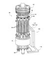
- the mounting head 28 mounts electronic components on the circuit board held by the transport device 22. As shown in FIGS. 2 to 4, the mounting head 28 includes twelve mounting units 66, and a suction nozzle 68 is mounted at the tip of each mounting unit 66. The suction nozzle 68 is attachable to and detachable from the mounting unit 66, and can be changed according to the size and shape of the electronic component. Furthermore, a cleaning tool (see FIG. 13) 70 described later can be attached to and detached from the mounting unit 66 and can be replaced with the suction nozzle 68.
- FIG. 2 is a perspective view showing the mounting head 28 in a state where it is detached from the slider 50.
- FIG. 3 is a perspective view showing the mounting head 28 with the cover removed.
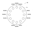
- FIG. 4 is a bottom view of the mounting head 28 as seen from the viewpoint of the mounting head 28 from below.
- Each suction nozzle 68 communicates with a positive / negative pressure supply device 72 (see FIG. 14) via negative pressure air and positive pressure air passages. Each suction nozzle 68 sucks and holds the electronic component by negative pressure, and releases the held electronic component by positive pressure.
- the mounting unit 66 having a generally shaft shape is held at an outer peripheral portion of the unit holder 74 at an equiangular pitch. The mounting unit 66 is held in a state where the axial direction is vertical.
- the suction nozzle 68 held at the tip of the mounting unit 66 extends downward from the lower surface of the unit holder 74. Thereby, as shown in FIG. 4, the 12 suction nozzles 68 are arranged on the circumference of 12 equally spaced.
- each of the twelve mounting units 66 is simultaneously rotated around each axis by a unit rotation device 76.
- the unit rotation device 76 includes a plurality of gears 78 provided at the upper ends of the plurality of mounting units 66 and one gear (not shown) that meshes with the plurality of gears 78. It is configured. Then, the plurality of gears 78 are rotated by the rotation of the one gear, so that the respective mounting units 66 are simultaneously rotated around the respective axis centers. Thereby, the holding posture of the electronic component sucked and held by each suction nozzle 68 can be changed.
- the unit holder 74 is supported by the head main body 80 of the mounting head 28 so as to be rotatable around its own axis.
- the unit holder 74 is rotated at an arbitrary angle by the holder rotating device 82.
- the plurality of suction nozzles 68 arranged on one circumference rotate at an arbitrary angle with the center of the circumference of the circumference as an axis.
- each mounting unit 66 a plurality of rollers 84 functioning as cam followers are provided at the upper end of each mounting unit 66.
- Each roller 84 is engaged with a cam surface of a cam (not shown) fixed to the head main body 80, and the height of the cam surface changes in the circumferential direction.
- Each mounting unit 66 is held by a unit holder 74 so as to be movable in the vertical direction. As a result, the mounting unit 66 moves in the vertical direction as the unit holder 74 rotates.
- the stop position that is farthest from the head body 80 among the plurality of stop positions of the mounting unit 66 is the mounting station.
- the mounting unit 66 stopped at the mounting station moves to the lowest position. That is, when the mounting head 28 moves on the circuit board, the suction nozzle 68 of the mounting unit 66 stopped at that station comes closest to the circuit board.
- the electronic component is mounted on the circuit board by the suction nozzle 68 stopped at the mounting station. Further, the electronic component supplied from the tape feeder 60 is sucked and held by the suction nozzle 68 stopped at the mounting station.
- a station located directly across the axis of the unit holder 74 of the mounting station is the first imaging station. That is, the stop position closest to the head main body 80 is the first imaging station.
- a camera support portion 86 fixed to the lower end portion of the head body 80 extends below the mounting unit 66 stopped at the first imaging station.
- a first part camera 88 is disposed on the upper surface of the camera support portion 86. The first parts camera 88 images the lower surface of the electronic component held by the suction nozzle 68.
- a receiving tray 90 is disposed below the camera support portion 86. As shown in FIGS. 2, 5, and 6, the receiving tray 90 has a generally annular shape and is fixed to the lower end portion of the head body 80. The receiving tray 90 is positioned below the twelve mounting units 66 arranged in an annular shape, and a groove 92 is formed in an annular shape on the upper surface of the receiving tray 90. With such a structure, the electronic component dropped from the suction nozzle 68 is accommodated in the groove 92 of the receiving tray 90.
- a through hole 94 is formed at a predetermined position in the groove 92, specifically, at a position corresponding to the lower portion of the mounting unit 66 positioned at the mounting station.
- the suction nozzle 68 extends below the tray 90 through the through hole 94, so that the mounting operation of the electronic component on the circuit board and the suction operation of the electronic component from the tape feeder 60 are ensured.
- a mark camera (see FIG. 14) 96 is disposed at the lower end of the slider 50 so as to face downward.
- the mark camera 96 images an arbitrary position on the frame unit 30.
- the station located upstream of the first imaging station is the second imaging station.
- a station located upstream of the mounting station is a third imaging station.
- the electronic component held by the suction nozzle 68 is imaged from the side.
- a head body 80 extends to the side of each of the second imaging station and the third imaging station.
- a second part camera 97 is attached to the lower end portion of the head main body 80 extending to the side of the second imaging station.
- a third part camera 98 is attached to the lower end portion of the head main body 80 extending to the side of the third imaging station.
- the side surface of the electronic component held by the suction nozzle 68 is imaged by the second parts camera 97
- the side surface of the electronic component held by the suction nozzle 68 is Images are taken by the third part camera 98.
- the station located downstream of the first imaging station is a disposal station.
- the electronic component held by the suction nozzle 68 is discarded.
- a head main body 80 extends to the side of the disposal station.
- a first disposal box 99 is fixed to the lower end portion of the head main body 80.
- the first disposal box 99 has a box shape with an open top, and the tip of the suction nozzle 68 is positioned above the opening. As a result, the electronic component held by the suction nozzle 68 is detached, and the detached electronic component is discarded in the first disposal box 99.
- each station when the unit holder 74 rotates in the forward direction, the unit holder 74 rotates clockwise in FIG.
- one mounting unit 66a out of the twelve mounting units 66a to 66l is located at the mounting station, that is, when the mounting unit 66a is moved to the lowermost position, the five mounting units 66e to 66e 66i is moving upward most.
- the mounting unit 66g located at the center of the five mounting units 66e to 66i is positioned at the first imaging station.
- the mounting unit 66f located on the upstream side of the mounting unit 66g is positioned in the second imaging station.
- the mounting unit 66h located on the downstream side of the mounting unit 66g is located in the disposal station.
- the third imaging station is located on the upstream side of the mounting station, and the mounting unit 66l is positioned in the third imaging station.
- the mounting unit 66e located on the upstream side of the mounting unit 66f sucks and holds the electronic components supplied from the bulk feeder (see FIG. 3) 100. That is, the station where the mounting unit 66e is stopped is the suction station for the bulk feeder. Note that the mounting station and the mounting units 66a and 66e stopped at the suction station are moved up and down by the unit elevating device (see FIG. 14) when mounting or sucking electronic components.
- the bulk feeder 100 will be described in detail.
- the bulk feeder 100 is attached to the head main body 80 of the mounting head 28. For this reason, the bulk feeder 100 is moved to an arbitrary position on the frame unit 30 together with the mounting head 28 by the moving device 24.
- the bulk feeder 100 includes a housing 114 in which two case members 110 and 112 are aligned with each other, and an arm member 116 fixed to the lower end portion of the housing 114.
- the arm member 116 is divided into a first arm part 118, a second arm part 120, and a third arm part 122.
- the first arm portion 118 reaches below the mounting unit 66 located at the suction station.
- the second arm part 120 is orthogonal to the first arm part 118 in the same plane.
- the third arm portion 122 is also orthogonal to the first arm portion 118 in the same plane, and extends in the direction opposite to the second arm portion 120.
- the arm member 116 is bolted to the head body 80 at the third arm portion 122, and is bolted to the housing 114 at the second arm portion 120.
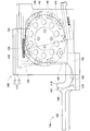
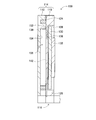
- the two case members 110 and 112 have a flat plate shape with a plate thickness, and are erected with their surfaces aligned. As shown in FIG. 11, which is a cross-sectional view taken along the line AA in FIG. 10, a concave portion 128 is formed on the surface 126 of the case member 110 opposite to the mating surface 124 to be matched with the case member 112. Inside the recess 128, a turntable 130 is disposed.
- the turntable 130 has a disk shape, and is held by the case member 110 so as to be rotatable about its central axis.
- the rotary disk 130 is provided with a rotation drive device 132.
- the rotating disk 130 is rotated by driving an electromagnetic motor (see FIG. 14) 134 included in the rotation driving device 132.
- an electromagnetic motor see FIG. 14
- FIG. 10 When the turntable 130 rotates in the forward direction, the turntable 130 shown in FIG. 10 rotates counterclockwise.
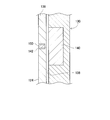
- FIG. 12 which is a cross-sectional view taken along the line BB in FIG.
- ten permanent magnets 140 are embedded at a location near the outer edge of the turntable 130.
- a groove 142 is formed in the mating surface 124 of the case member 110. As shown in FIG. 10, the groove 142 is divided into an annular groove 144 and a vertical groove 146.
- the annular groove 144 has a partial annular shape centering on the rotation axis of the rotating disk 130.
- the vertical groove portion 146 is continuous from the end of the annular groove portion 144 and extends generally in the vertical direction.
- the annular groove portion 144 is formed at a position along the turning trajectory of the permanent magnet 140 accompanying the rotation of the turntable 130.
- the annular groove 144 extends from the lowermost end of the turning trajectory of the permanent magnet 140 in the rotational direction of the rotating disk 130 in the forward rotation, and passes through the uppermost end of the turning trajectory of the permanent magnet 140 to the foremost end (arm member 116). To the end of the side).
- the up-down direction groove part 146 continues from the foremost end that extends downward from the annular groove part 144 and extends downward. And it curves toward the front (direction toward the arm member 116) and opens on the front side surface of the case member 110 in a generally horizontal state.
- the depth of the groove 142 is slightly deeper than the height of the electronic component 150, and the width of the groove 142 is slightly larger than the width of the electronic component 150.
- the electronic component 150 is accommodated in the groove 142 in a posture in which the width direction thereof is the width direction of the groove 142.
- the case member 112 is aligned with the case member 110 on the alignment surface 152.
- a concave portion 154 is formed on the mating surface 152.
- the recess 154 is generally semicircular, and extends backward from a part of the annular groove 144, specifically, from the lowermost end of the annular groove 144 to reach the uppermost end. It covers the part.
- the two case members 110 and 112 are mated with each other at the mating surfaces 124 and 152, and the opening of the recess 154 is closed by the bottom 136. Accordingly, the storage portion 156 is defined by the concave portion 154 of the case member 112 and the bottom portion 136 of the case member 110.
- the portion covered by the concave portion 154 of the annular groove portion 144 opens into the storage portion 156. Further, the annular groove portion 144 is formed along the turning trajectory of the permanent magnet 140 as described above. For this reason, the electronic component accommodated in the accommodating part 156 is accommodated in the annular groove part 144 by the magnetic force of the permanent magnet 140. Then, the rotation platen 130 rotates in the forward direction by driving the rotation driving device 132, so that the electronic component housed in the annular groove portion 144 moves in the rotation direction of the turntable 130.
- the portion of the annular groove 144 that is not covered by the recess 154 is closed by the mating surface 152 of the case member 112. That is, a portion of the annular groove 144 that is not covered by the recess 154 has a tunnel shape. For this reason, when the electronic component accommodated in the annular groove portion 144 reaches the tunnel-shaped annular groove portion 144 as the turntable 130 rotates, the electronic component protruding from the annular groove portion 144 is The side wall 158 of 154 prevents entry into the tunnel-shaped annular groove 144.
- the side wall 158 located at the diameter portion of the semicircular recess 154 is generally erected in the vertical direction.
- the upper end portion of the side wall 158 is located near the uppermost end of the annular groove portion 144.
- the annular groove portion 144 located on the upstream side of the side wall 158 opens into the storage portion 156.
- the annular groove portion 144 positioned on the downstream side of the side wall 158 has a tunnel shape. For this reason, the electronic component protruding from the annular groove 144 contacts the side wall 158 in the vicinity of the uppermost end of the annular groove 144. As a result, only the electronic components appropriately accommodated in the annular groove portion 144 are sent out from the accommodating portion 156.
- an air groove 160 for supplying air is also formed on the mating surface 124 where the groove 142 is formed.
- the air groove 160 is formed to extend in the vertical direction, and a lower end portion thereof is connected to a boundary portion between the annular groove portion 144 and the vertical groove portion 146.
- the air groove 160 communicates with an air passage (not shown) connected to an air supply device (not shown) at the upper end. Thereby, the compressed air is jetted into the vertical groove portion 146 via the air groove 160.
- an open / close valve (not shown) is provided in the air passage, and supply and shutoff of compressed air are controlled by operation of a solenoid (see FIG. 14) 164 of the open / close valve.
- a groove 166 is formed on the upper surface of the arm member 116.
- the proximal end portion of the groove 166 is connected to the distal end portion of the vertical groove portion 146 formed in the case member 110.
- the groove 166 is curved toward the first arm portion 118 and extends to the end surface of the first arm portion 118.
- a pin 167 is erected in the groove 166 in the vicinity of the end face, and the electronic component sent out in the groove 166 is stopped by the pin 167. That is, the location where the pin 167 is erected is the electronic component supply position of the bulk feeder 100.
- Two air grooves 168 and 170 are further formed on the upper surface of the arm member 116.
- the air grooves 168 and 170 are continuous with the curved portion of the groove 166.
- the air passages are also communicated with the air grooves 168 and 170 so that the compressed air is ejected through the groove 166 toward the end face of the first arm portion 118.
- Air groove 168 is connected to the upstream end of the curved portion of groove 166
- air groove 170 is connected to the downstream end of the curved portion of groove 166.
- the electronic parts are stored in a separate state in the storage unit 156. Then, a plurality of electronic components in a disassembled state are sent out to the supply position in a state where they are aligned in one row.
- the electronic component housed in the housing portion 156 is housed in the annular groove portion 144 by the magnetic force of the permanent magnet 140.
- the rotating disk 130 is rotated by driving the rotation driving device 132, so that the electronic components in the annular groove portion 144 move in the rotation direction of the rotating disk 130. At this time, a plurality of electronic components are aligned in one row inside the annular groove portion 144.
- the electronic component moves from the inside of the annular groove 144 to the inside of the vertical groove 146.
- the electronic component moves downward by gravity inside the vertical groove 146.
- the electronic component is sent out to the groove 166 through the inside of the vertical groove part 146 by the air jetted from the air groove 160 into the vertical groove part 146.
- the electronic component sent out to the groove 166 is further sent out toward the end face of the first arm portion 118 by the air blown into the groove 166 from the air grooves 168 and 170.
- the electronic component comes into contact with a pin 167 provided upright in the groove 166.
- the plurality of electronic components accommodated in a bulk shape are sent out to the supply position in a state of being aligned in one row.
- the electronic component sent to the supply position is held by the suction nozzle 68e of the mounting unit 66e stopped at the suction station.
- a second disposal box 176 and a work tool changer 178 are provided on the frame portion 30 of the mounting machine 16 between the supply device 26 and the transport device 22.
- the second disposal box 176 has a box shape with an open top, and the electronic components accumulated in the groove 92 of the receiving tray 90 are discarded.
- the work tool changer 178 houses the suction nozzle 68, and the suction nozzle 68 mounted on the mounting unit 66 and the suction nozzle 68 stored in the work tool changer 178 can be automatically replaced. is there. Further, the work tool changer 178 also stores a cleaning tool (see FIG. 13) 70. The suction nozzle 68 mounted on the mounting unit 66 and the cleaning tool 70 stored in the work tool changer 178 are automatically set. It is possible to exchange with.
- the cleaning tool 70 is for cleaning the lens of the first part camera 88 and the inside of the groove 92 of the receiving tray 90.
- the cleaning tool 70 includes a lens cleaner 180, a cleaning brush 182, and a support member 184.
- the support member 184 is generally rod-shaped and has a bent portion 186 that bends in a crank shape.
- the lens cleaner 180 is configured by relatively soft flocking, and is attached to the upper end of the bent portion 186.
- the cleaning brush 182 is configured by flocking that is harder than the flocking of the lens cleaner 180, and is attached to the lower end of the bent portion 186.
- the tip of the flocked lens cleaner 180 contacts the lens of the first part camera 88, and the tip of the flocked brush 182 has a flocked tip 92 of the receiving tray 90. It touches the bottom of the inside. Further, the bent portion 186 is bent so as to avoid the camera support portion 86 and the first part camera 88, and the cleaning tool 70 makes contact with the camera support portion 86 and the first part camera 88 at the bent portion 186. It is avoiding.
- the mounting machine 16 includes a control device 190 as shown in FIG.
- the control device 190 includes a controller 192 and a plurality of drive circuits 194.
- the plurality of drive circuits 194 include the electromagnetic motors 46, 52, 54, 134, the substrate holding device 48, the delivery device 62, the positive / negative pressure supply device 72, the unit rotation device 76, the holding body rotation device 82, the unit lifting device 106, and a solenoid. 164.
- the controller 192 includes a CPU, a ROM, a RAM, and the like, mainly a computer, and is connected to a plurality of drive circuits 194. Accordingly, the operations of the transport device 22 and the moving device 24 are controlled by the controller 192.
- the controller 192 is also connected to the image processing device 196.
- the image processing device 196 processes image data obtained by the first part camera 88, the mark camera 96, the second part camera 97, and the third part camera 98. Thereby, the controller 192 can obtain various information based on the image data. Further, the controller 192 is also connected to the display device 198, and various information is displayed on the display device 198.
- the mounting machine 16 can perform a mounting operation for mounting an electronic component on a circuit board with the above-described configuration. More specifically, first, according to a command from the controller 192, the circuit board is transported to the mounting work position, and the circuit board is fixedly held at that position. Next, the controller 192 moves the mounting head 28 onto the circuit board. Then, the circuit board is imaged by the mark camera 96, and the imaged data is processed by the image processing device 196. Thereby, the controller 192 acquires the holding position error of the circuit board by the conveyor devices 40 and 42.
- the controller 192 supplies electronic components corresponding to the type of the circuit board at each supply position by the tape feeder 60 or the bulk feeder 100.
- the supplied electronic component is held by the suction nozzle 68 of the mounting head 28.
- the electronic component supplied by the bulk feeder 100 is held by the suction nozzle 68 stopped at the suction station.
- the electronic component supplied by the tape feeder 60 is held by the suction nozzle 68 stopped at the mounting station.
- the electronic component supplied by the tape feeder 60 is sucked and held, it is necessary to move the mounting head 28 to a supply position by the tape feeder 60.
- the electronic components supplied by the bulk feeder 100 are sucked and held, there is no need to move the mounting head 28. For this reason, it is possible to work efficiently.
- the controller 192 rotates the unit holding body 74.
- the unit holder 74 is intermittently rotated by the holder rotating device 82 by an angle equal to the arrangement angle pitch of the mounting unit 66. For this reason, every time the unit holder 74 rotates intermittently, the suction nozzle 68 that does not hold electronic components stops at the mounting station or the suction station. As a result, the electronic components are sequentially held every intermittent rotation of the unit holder 74.
- the second parts camera 97 images the electronic component held by the suction nozzle 68. . Then, the controller 192 processes the captured image data with the image processing device 196, and determines whether the holding posture of the electronic component by the suction nozzle 68 is appropriate.
- the second parts camera 97 acquires the vertical dimension, horizontal dimension, and the like of the held electronic component in order to image the electronic component held by the suction nozzle 68 from the side.
- the vertical dimension, horizontal dimension, and the like of the electronic component when the electronic component is properly mounted on the circuit board are stored in the controller 192 of the control device 190. For this reason, when the dimension of the electronic component memorize
- the holding posture of the electronic component by the suction nozzle 68 is not appropriate. As described above, whether or not the holding posture of the electronic component is appropriate is determined in the second imaging station.
- the controller 192 rotates the unit holder 74 intermittently. Thereby, the suction nozzle 68 moves from the second imaging station to the first imaging station. In this first imaging station, the electronic parts held by the suction nozzle 68 are imaged by the first parts camera 88. Then, the imaging data is processed by the image processing device 196 to determine whether the electronic component held by the suction nozzle 68 is good, that is, whether the electronic component is normal.
- the controller 192 acquires the shape, area, and the like of the lower surface of the held electronic component.
- the shape, area, etc. of the actual lower surface of the electronic component are stored in the controller 192 of the control device 190.
- the shape, area, etc. of the electronic component stored in the controller 192 differ from the shape, area, etc. of the electronic component based on the imaging data, it is considered that a part of the electronic component is missing. . That is, it is considered that the electronic component is not normal.
- the shape, area, etc. of the electronic component stored in the controller 192 match the shape, area, etc.
- the electronic component is considered normal. In this way, in the first imaging station, it is determined whether or not the electronic component is normal. It should be noted that the determination at the first imaging station is not performed for an electronic component that is not good at the second imaging station, that is, an electronic component that is not held in an appropriate posture by the suction nozzle 68. This is because an electronic component that is not held in an appropriate posture by the suction nozzle 68 is not mounted on the circuit board.
- the suction nozzle 68 moves from the first imaging station to the disposal station.
- this disposal station electronic components that are not held in an appropriate posture by the suction nozzle 68 and electronic components that are not normal are discarded. In other words, electronic components that are not well determined in the first imaging station and the second imaging station are discarded.
- the suction nozzle 68 In the third imaging station on the upstream side of the mounting station, it is determined whether or not an electronic component is held by the suction nozzle 68. Specifically, the tip of the suction nozzle 68 is imaged by the third parts camera 98. Then, the imaging data is processed by the image processing device 196 to determine whether or not an electronic component is held by the suction nozzle 68. As described above, since the disposal operation of the electronic component is performed at the disposal station, the suction nozzle 68 may not hold the electronic component due to the disposal of the electronic component. In addition to that case, the electronic component may unexpectedly fall from the suction nozzle 68.
- the controller 192 stores the number of times that the suction nozzle 68 is determined not to hold an electronic component in the third station. In other words, the controller 192 manages the number of electronic components that have left the suction nozzle 68 due to disposal and dropping.
- the mounting head 28 is provided with the bulk feeder 100, and it is not necessary to move the mounting head 28 to the electronic component supply position.
- the electronic component holding operation from the bulk feeder 100 is performed at the suction station, and the electronic component mounting operation on the circuit board is performed at the mounting station. For this reason, it is possible to perform holding work and mounting work simultaneously.
- the suction nozzle 68 holding the electronic component stops at the disposal station by intermittently rotating the unit holder 74. For this reason, it is not necessary to move the mounting head 28 even when the electronic component is discarded.
- the disposal station where the disposal operation is performed is a position different from the suction station and the mounting station.
- the disposal operation of the electronic components in the first disposal box 99 is automatically performed without stopping the mounting machine 16, but the operation of collecting the electronic components from the first disposal box 99 is performed by the operator. Need to be done manually.
- the mounting machine 16 needs to be stopped, which may reduce the throughput. For this reason, in the mounting machine 16, the collection
- the controller 192 the number of electronic components discarded in the first disposal box 99 (hereinafter, may be abbreviated as “disposal components”) is managed as described above.
- the average number of discarded parts (hereinafter, may be abbreviated as “average number of discarded items”) ⁇ generated during the mounting operation is calculated.
- the controller 192 obtains the number K of waste parts accommodated in the first waste box 99 every time the mounting work on one circuit board is completed. Then, the controller 192 calculates the minimum value of N that satisfies the following expression. N is a natural number.
- K 0 is the first set threshold number, and is set to the number of electronic components that can be accommodated in the first discard box 99.
- the second circuit board is moved to.
- the number of discarded parts at the end of the mounting operation is estimated to be (K + ⁇ ). That is, it is estimated that the number of discarded parts at the end of the mounting work on the (N + 1) th circuit board is ⁇ K + ( ⁇ ⁇ N) ⁇ . For this reason, at the end of the mounting operation on the (N + 1) -th circuit board, it is necessary to discard ⁇ K + ( ⁇ ⁇ N) ⁇ waste parts in the first waste box 99.
- the controller 192 calculates the minimum value of N when ⁇ K + ( ⁇ ⁇ N) ⁇ exceeds K 0, and before the (N + 1) -th circuit board mounting operation is performed, that is, the N-th sheet. The end of the circuit board mounting operation is determined as the recovery timing of the discarded parts. As a result, it is possible to determine immediately before the waste parts overflow from the first waste box 99 as the collection timing of the waste parts.
- the controller 192 determines the end of the mounting operation on the fourth circuit board as the recovery timing of the discarded parts. Then, the controller 192 displays a notification on the display device 198 that the end of the mounting operation of the fourth circuit board is the most suitable timing for the recovery operation of the discarded parts.
- the operator performs the recovery operation of the waste component by using the replacement time of the fourth circuit board and the fifth circuit board by performing the recovery operation of the waste component according to the display on the display device 198. Is possible. As a result, it is possible to suppress a decrease in throughput associated with the recovery operation of the discarded parts. In addition, since the waste parts are collected from the first waste box 99 immediately before the waste parts overflow from the first waste box 99, it is possible to reduce the number of times the waste parts are collected.
- the first set threshold value K 0 refers to the ratio of the volume of the storage unit 156 to the number of electronic components that can be stored in the storage unit 156 of the bulk feeder 100 (hereinafter sometimes referred to as “volume ratio”).
- volume ratio the ratio of the volume of the storage unit 156 to the number of electronic components that can be stored in the storage unit 156 of the bulk feeder 100.
- the controller 192 the calculation is performed. Specifically, since there are gaps between the plurality of electronic components accommodated in the first disposal box 99, the number of disposal components that can be accommodated in the first disposal box 99, that is, the first set threshold number K. It is difficult to set 0 appropriately. However, if the volume required for one electronic component in the first disposal box 99 can be estimated appropriately, the first set threshold number K 0 can be set appropriately.
- the electronic component discarded in the first disposal box 99 is the same as the electronic component stored in the storage unit 156 of the bulk feeder 100.
- the volume ratio is an average value of volumes required for one electronic component in the storage unit 156. For this reason, the volume ratio can be considered as an average value of the volume required for one electronic component in the first disposal box 99. Therefore, the controller 192, the value obtained by dividing the volume of the first waste box 99 at a volume ratio is set as a first set threshold number K 0. As a result, the first set threshold number K 0 can be set appropriately.
- the mounting machine 16 even when ⁇ K + ( ⁇ ⁇ N) ⁇ exceeds K 0 , the mounting machine 16 is supplied to the bulk feeder 100 at the time of mounting work on the Nth and subsequent sheets, that is, the (N + 1) th circuit board.
- the time of replenishment is determined as the collection timing of the discarded parts.
- ⁇ K + ( ⁇ ⁇ 4) ⁇ exceeds K 0 during the mounting operation on the fifth circuit board. That is, it is presumed that waste components overflow from the first waste box 99 during the mounting operation on the fifth circuit board.
- the fifth circuit board is mounted, the number of discarded parts increases as shown by the one-dot chain line in the figure.
- the number of discarded parts in recovery operations performed at the time of replenishment of the electronic components to the bulk feeder 100 becomes a number substantially the same as the first set threshold number K 0, discarding parts of the recovery operation performed when replacement of the circuit board Is greater than the number K 1 (see FIG. 15). Thereby, it is possible to further reduce the number of operations of collecting the waste parts.
- the controller 192 of the control device 190 includes a disposal box accommodation number acquisition unit 200, a set threshold number determination unit 202, a disposal part number acquisition unit 204, a disposal box collection timing determination unit 206, a collection timing notification. Part 208 is provided.
- the disposal box accommodation number acquisition unit 200 is a functional unit for obtaining the number of electronic components housed in the first disposal box 99.
- the set threshold number determination unit 202 is a functional unit for determining the first set threshold number K 0 based on the volume and the volume ratio of the first discard box 99.
- the discarded component number acquisition unit 204 is a functional unit for calculating the discarded average number ⁇ .
- the disposal box collection timing determination unit 206 is a functional unit for determining the timing for collecting electronic components from the first disposal box 99.
- the collection timing notification unit 208 is a functional unit for displaying on the display device 198 the timing at which the electronic component is collected from the first disposal box 99.
- the annular receiving tray 90 is disposed below the annular mounting unit 66, and the electronic component that has unexpectedly dropped from the suction nozzle 68. Is received in the groove 92 of the receiving tray 90. Thereby, it is possible to prevent the electronic component from falling onto the circuit board. Furthermore, the mounting machine 16 can automatically discard the electronic component housed in the groove 92 in the second disposal box 176.
- the controller 192 manages the number of electronic components detached from the suction nozzle 68 due to disposal and dropping in the third imaging station.
- the number of electronic components discarded in the first disposal box 99 is also managed at the disposal station.
- the controller 192 calculates the number of electronic components that have fallen into the groove 92 of the tray 90 (hereinafter, may be abbreviated as “the number of drops”). Then, it is determined whether or not the number of drops exceeds the second set threshold number.
- the second set threshold number is set to the number of electronic components that can be accommodated in the groove 92.
- the suction nozzle 68 attached to the attachment unit 66 is attached to the cleaning tool 70 housed in the work tool changer 178 in order to clean the inside of the groove 92.
- the controller 192 moves the mounting head 28 onto the work tool changer 178.
- the mounting unit 66 located at the mounting station is moved downward and protrudes below the receiving tray 90 through the through hole 94.
- the suction nozzle 68 is removed from the mounting unit 66, and the cleaning tool 70 is mounted on the mounting unit 66.
- the mounting unit 66 on which the cleaning tool 70 is mounted is moved upward. Thereby, the lower end portion of the cleaning brush 182 of the cleaning tool 70 is disposed in the groove 92.
- the controller 192 moves the mounting head 28 onto the second disposal box 176. Then, the unit holder 74 is rotated once. Thereby, the lower end part of the cleaning brush 182 moves clockwise through the groove 92 from the through hole 94 shown in FIG. At this time, the lower end portion of the cleaning brush 182 is in sliding contact with the bottom surface in the groove 92, and the electronic components accommodated in the groove 92 are accumulated. The integrated electronic component reaches the through hole 94 and falls from the through hole 94. As a result, the electronic component accommodated in the groove 92 is discarded in the second disposal box 176.
- the controller 192 moves the mounting unit 66 located at the mounting station, that is, the mounting unit 66 to which the cleaning tool 70 is mounted, downward and rotates around the axis.
- the mounting unit 66 is rotated 90 ° in one direction and then rotated 180 ° in the other direction. Then, the rotation operation is repeated three times. As a result, electronic components that have entered the cleaning brush 182 are also discarded in the second disposal box 176.
- the lens of the first part camera 88 is also cleaned.
- the lens cleaner 180 is also mounted on the cleaning tool 70, and when the mounting unit 66 holding the cleaning tool 70 moves to the first imaging station, as shown in FIG. Is in contact with the lens of the first part camera 88. Then, the lens 70 of the first part camera 88 is wiped by the lens cleaner 180 as the cleaning tool 70 moves as the unit holder 74 rotates. Further, when an electronic component is dropped on the lens, the electronic component falls into the groove 92 and is collected by the cleaning brush 182.
- the receiving tray 90 prevents the electronic components from falling onto the circuit board, and the electronic components accommodated in the receiving tray 90 are automatically discarded in the second disposal box 176. Is done. Further, the lens of the first part camera 88 is automatically cleaned. As a result, it is possible to realize a system that is highly automated.
- the controller 192 of the control device 190 includes a drop number acquisition unit 210, a cleaning timing determination unit 212, and a cleaning tool operation control unit 214, as shown in FIG.
- the falling number acquisition unit 210 is a functional unit for acquiring the number of electronic components that have dropped into the groove 92 of the receiving tray 90.
- the cleaning timing determination unit 212 is a functional unit for determining the timing for cleaning the inside of the groove 92 and discarding the electronic component in the groove 92.
- the cleaning tool operation control unit 214 is a functional unit for performing the cleaning operation in the groove 92 by the cleaning tool 70 at the timing determined by the cleaning timing determination unit 212.
- the lens cleaner 180 and the cleaning brush 182 are separately attached to the support member 184.
- the lens cleaner and the cleaning brush can be integrally formed.
- a cleaning tool 224 having an integrally molded cleaning brush 220 and lens cleaner 222 is shown in FIGS.
- the mounting head 226 to which the cleaning tool 224 is attached has the same configuration as the mounting head 28 except for the first parts camera 228 and the receiving tray 230. For this reason, the description of components having the same functions as those of the mounting head 28 will be omitted or simplified by using the same reference numerals.
- the cleaning brush 220 is composed of a plurality of flocks bundled in a cylindrical shape.
- the lens cleaner 222 is constituted by a plurality of flocks bundled in an annular shape around the outer periphery of the cleaning brush 220.
- the flocking of the lens cleaner 222 is softer and shorter than the flocking of the cleaning brush 220.
- the flocking of the lens cleaner 222 and the flocking of the cleaning brush 220 are integrally held by the holder 232 at each upper end portion.
- the tip of the hair transplantation of the cleaning brush 220 contacts the bottom surface of the groove 234 of the receiving tray 230, and the tip of the hair transplantation of the lens cleaner 222 is the first.
- the lens of the part camera 228 is contacted.
- the tip of the flock of the lens cleaner 222 contacts the lens, the tip of the flock of the cleaning brush 220 is discharged from the groove 234 as shown in FIG. This is because the flocking of the cleaning brush 220 is separated on both sides of the first part camera 228 by the support base 236 that supports the first part camera 228.
- the support base 236 is streamlined from the viewpoint from above, and has a taper surface 238 extending in the circumferential direction of the receiving tray 230. For this reason, when the mounting unit 66 to which the cleaning tool 224 is mounted moves toward the first imaging station by the rotation of the unit holder 74, the flocking of the cleaning brush 220 contacts the taper surface 238. Then, the flocking of the cleaning brush 220 is separated by the taper surface 238 into both sides of the first part camera 228. As a result, contact between the relatively hard flocking of the cleaning brush 220 and the lens of the first part camera 228 is prevented.
- a through hole 240 is formed in the groove 234 of the receiving tray 230 at a position corresponding to the lower side of the support base 236. This makes it possible to discard the electronic component from the through hole 240 before the tip of the flocked brush 220 is discharged from the groove 234.
- a through hole 242 is also formed in the groove 234 at a position corresponding to the lower part of the mounting station, and electronic components are discarded from the through hole 242 as well.
- the electronic component mounting machine 16 is an example of an electronic component mounting machine.
- the mounting head moving device 24 is an example of a moving device.
- the mounting heads 28 and 226 are examples of mounting heads.
- the suction nozzle 68 is an example of a holder.
- the cleaning tools 70 and 224 are examples of an accumulation mechanism and a cleaning member.
- the first parts camera 88 is an example of an imaging device.
- the receiving trays 90 and 230 are an example of a detached part accommodating portion and a receiving portion.
- the through holes 94, 240, and 242 are examples of through holes.
- the first disposal box 99 is an example of a detached component storage unit and a disposal component storage unit.
- the bulk feeder 100 is an example of a bulk feeder.
- the grooves 142 and 166 are an example of a supply passage.
- the storage unit 156 is an example of a storage unit.
- Lens cleaners 180 and 222 are examples of lens cleaners.
- Cleaning brushes 182 and 220 are examples of cleaning brushes.
- the support member 184 is an example of a holding member.
- the bent portion 186 is an example of a bent portion.
- the control device 190 is an example of a control device.
- the disposal box accommodation number acquisition unit 200 and the fall number acquisition unit 210 are examples of the accommodation number acquisition unit.
- the setting threshold number determination unit 202 is an example of a setting threshold number determination unit.
- the discarded component number acquisition unit 204 is an example of a discarded component number acquisition unit.
- the waste box collection timing determination unit 206 and the cleaning timing determination unit 212 are examples of a collection timing determination unit.
- the cleaning tool operation control unit 214 is an example of an accumulation mechanism operation control unit.
- the support base 236 is an example of a lens support base.
- the taper surface 238 is an example of a taper surface.
- the number of electronic components accommodated in the first disposal box 99 is estimated from the number of positive pressures supplied to the suction nozzle 68. Further, the number of electronic components accommodated in the groove 92 of the receiving tray 90 is estimated based on the imaging data. As described above, the number of accommodations in the first disposal box 99 and the groove 92 may be acquired by various estimation methods or may be acquired by actual measurement. That is, a sensor or the like may be provided at the opening of the first disposal box 99 and the groove 92, and the accommodation number may be actually measured using the sensor.
- the discard average number ⁇ and the set threshold number K 0 are calculated in the controller 192.
- the operator can input the discard average number ⁇ and the set threshold number K 0. .
- the electronic components in the groove 92 of the receiving tray 90 are integrated by the cleaning brush, but the electronic components can be integrated by various mechanisms.
- the electronic components may be integrated toward the through hole 94 by inclining the receiving tray 90 toward the through hole 94.
- the generally cylindrical cleaning tool 224 is employed, but various shapes of cleaning tools can be employed. Specifically, for example, as shown in FIG. 20, it is possible to employ a generally plate-shaped cleaning tool 250.
- the cleaning tool 250 includes a cleaning brush 252, a lens cleaner 254, and a holder 256.
- the cleaning brush 252 is configured by a plurality of flocks bundled in a plate shape.
- the lens cleaner 254 is configured by a plurality of flocks bundled in a plate shape along one surface of the cleaning brush 252. The flocking of the lens cleaner 254 is softer and shorter than the flocking of the cleaning brush 252.
- the flocking of the lens cleaner 254 and the flocking of the cleaning brush 252 are integrally held by the holder 256 at each upper end portion.
- the cleaning tool 250 configured in this way the same effect as the cleaning tool 224 can be obtained.
- the cleaning tool 250 mounted on the mounting unit 66 is preferably moved in a state where the lens cleaner 254 is disposed in front of the cleaning brush 252 when cleaning the groove. This is because when the lens cleaner 254 disposed in the front drops the electronic component on the lens into the groove, the cleaning brush 252 disposed in the rear accumulates the dropped electronic component.
- the cleaning tool is detachably mounted on the mounting unit 66, but may be fixedly provided on the lower surface of the unit holder 74. Since the cleaning tool is fixedly provided on the unit holding body 74, it is possible to omit the replacement work of the suction nozzle 68 and the cleaning tool. However, since the cleaning tool fixed to the unit holder 74 becomes an obstacle during normal mounting work, it is necessary to attach a mechanism that can move in the vertical direction.
- the electronic component is detached from the suction nozzle 68 using positive pressure during the disposal operation.
- the electronic component can be detached from the suction nozzle 68 by various methods. It is. Specifically, for example, a suction port may be provided in a disposal box or the like, and the electronic component may be sucked from the suction nozzle 68 by the suction port.
- the position of the disposal station is not specifically limited, and may be set at any position. However, since it is necessary to make various determinations using imaging data, it is desirable to set the position of the discard station on the downstream side of the first imaging station and the second imaging station. Further, it is desirable that the position of the disposal station is set on the upstream side of the suction station so that abnormal electronic components or the like are not mounted on the circuit board.
Landscapes
- Engineering & Computer Science (AREA)
- Manufacturing & Machinery (AREA)
- Microelectronics & Electronic Packaging (AREA)
- Operations Research (AREA)
- Supply And Installment Of Electrical Components (AREA)
- Cleaning In General (AREA)
Abstract
回路基板に装着される電子部品を保持するための保持具と、保持具から離脱した電子部品を収容する離脱部品収容部とを備えた電子部品装着機において、離脱部品収容部に収容された電子部品の数(廃棄数)と、予め設定された設定閾数K0とに基づいて、離脱部品収容部から電子部品を回収するタイミングを決定する。具体的には、例えば、1枚の回路基板に発生する廃棄部品の平均数αと廃棄数K1とを合計し、その合計数が5枚目の回路基板に対する装着作業時に、設定閾数を超える場合には、4枚目の回路基板と5枚目の回路基板との入替作業時を、回収タイミングに決定する。これにより、好適なタイミングで離脱部品収容部から電子部品を回収することが可能となる。
Description
本発明は、回路基板に装着される電子部品を保持するための保持具と、その保持具から離脱した電子部品を収容する離脱部品収容部とを備えた電子部品装着機に関するものである。
回路基板に電子部品を装着する電子部品装着機では、保持具によって電子部品が保持され、その電子部品が回路基板に装着される。ただし、保持具によって保持された装着部品が、不良品である場合があり、そのような場合には、装着部品を廃棄する必要がある。このため、下記特許文献1に記載されているように、廃棄ボックス等の部品収容部が、作業機に設けられており、その部品収容部の上方で、保持具が電子部品を離脱することで、電子部品が部品収容部に廃棄される。
また、廃棄作業時には、保持具からの電子部品の離脱は、意図的に行われるが、保持具から電子部品が、不意に離脱する場合がある。つまり、電子部品が、保持具から落下する場合がある。このように、電子部品が保持具から不意に離脱すると、回路基板上に電子部品が落下する虞がある。このため、下記特許文献2に記載の電子部品装着機では、保持具の下方に部品収容部が配設されている。これにより、保持具から落下した電子部品が、その部品収容部に収容され、回路基板上への電子部品の落下が防止されている。
上記特許文献に記載の電子部品装着機によれば、良好でない電子部品等を好適に廃棄することが可能となる。また、保持具から不意に離脱した電子部品が、回路基板上へ落下することを好適に防止できる。しかし、廃棄部品を収容するための部品収容部,落下した電子部品を収容するための部品収容部は、概して小さく、大量の部品を収容することができない。このため、作業者が、部品収容部から電子部品を回収する必要がある。ただし、空に近い状態の部品収容部から電子部品を回収することは、無駄な作業である。一方、多くの電子部品が部品収容部に廃棄若しくは落下すると、電子部品が部品収容部から溢れ出る虞がある。本発明は、そのような実情に鑑みてなされたものであり、好適なタイミングで部品収容部から電子部品を回収することが可能な電子部品装着機を提供する。
上記課題を解決するために、本願の請求項1に記載の電子部品装着機は、回路基板に装着される電子部品を保持するための保持具と、前記保持具から離脱した電子部品を収容する離脱部品収容部とを備えた電子部品装着機であって、前記離脱部品収容部に収容された電子部品の数を取得する収容数取得部と、前記収容数取得部によって取得された電子部品の数と、予め設定された設定閾数とに基づいて、前記離脱部品収容部から電子部品を回収する回収タイミングを決定する回収タイミング決定部とを有する制御装置を備えることを特徴とする。
また、請求項2に記載の電子部品装着機は、請求項1に記載の電子部品装着機において、前記保持具によって廃棄された電子部品を収容する廃棄部品収容部を備え、その廃棄部品収容部が、前記保持具によって廃棄された電子部品を、前記保持具から離脱した電子部品として収容することで、前記離脱部品収容部として機能することを特徴とする。
また、請求項3に記載の電子部品装着機は、請求項2に記載の電子部品装着機において、複数の電子部品をばらの状態で収納する収納部と、その収納部に収納された電子部品を1列に整列させた状態で電子部品の供給位置まで導く供給通路とを備え、前記供給位置において電子部品を供給するバルクフィーダと、前記保持具を有する装着ヘッドと、その装着ヘッドを任意の位置に移動させる移動装置とを備え、前記バルクフィーダと前記廃棄部品収容部とが、前記装着ヘッドに固定的に連結され、その装着ヘッドと共に、前記移動装置によって任意の位置に移動可能とされたことを特徴とする。
また、請求項4に記載の電子部品装着機では、請求項3に記載の電子部品装着機において、前記制御装置が、前記収納部に収納可能な電子部品の数に対する前記収納部の容積の比率と、前記廃棄部品収容部の容積とに基づいて、前記設定閾数を決定する設定閾数決定部を有することを特徴とする。
また、請求項5に記載の電子部品装着機では、請求項3または請求項4に記載の電子部品装着機において、前記回収タイミング決定部が、1枚の回路基板に対する装着作業時に廃棄される電子部品の数を取得する廃棄部品数取得部を有し、1枚の回路基板に対する装着作業終了時に前記収容数取得部によって取得される電子部品の数と、前記廃棄部品数取得部によって取得される電子部品の数との合計数が、前記設定閾数を超える場合に、その1枚の回路基板に対する装着作業終了時を前記回収タイミングとして決定することを特徴とする。
また、請求項6に記載の電子部品装着機では、請求項5に記載の電子部品装着機において、前記回収タイミング決定部が、1枚の回路基板に対する装着作業終了時に前記収容数取得部によって取得される電子部品の数と、前記廃棄部品数取得部によって取得される電子部品の数との合計数が、前記設定閾数を超える場合であっても、その1枚の回路基板以降の回路基板に対する装着作業時に、前記収納部に電子部品が補給される際には、前記収納部への電子部品補給時を前記回収タイミングとして決定することを特徴とする。
また、請求項7に記載の電子部品装着機は、請求項1に記載の電子部品装着機において、前記保持具を保持する装着ヘッドと、前記保持具の下方に設けられ、前記保持具から落下した電子部品を受け取る受取部と、その受取部に落下した電子部品を集積する集積機構とを備え、前記受取部が、前記保持具から落下した電子部品を、前記保持具から離脱した電子部品として収容することで、前記離脱部品収容部として機能し、前記制御装置が、前記回収タイミング決定部によって決定された前記回収タイミングで、前記集積機構の作動を制御し、電子部品を集積させる集積機構作動制御部を有することを特徴とする。
また、請求項8に記載の電子部品装着機では、請求項7に記載の電子部品装着機において、前記集積機構が、前記受取部に落下した電子部品を、前記受取部に形成された貫通穴に向かって集積することを特徴とする。
また、請求項9に記載の電子部品装着機では、請求項7または請求項8に記載の電子部品装着機において、前記装着ヘッドが、複数の前記保持具を円環状に配置させた状態で保持することを特徴とする。
また、請求項10に記載の電子部品装着機では、請求項7ないし請求項9のいずれか1つに記載の電子部品装着機において、前記集積機構が、前記受取部の電子部品を受け取る受取面に沿って移動する清掃部材を有し、その清掃部材によって、前記受取部に落下した電子部品を掃き集めることを特徴とする。
また、請求項11に記載の電子部品装着機では、請求項10に記載の電子部品装着機において、前記装着ヘッドが、前記保持具を着脱可能に保持するとともに、前記清掃部材をも着脱可能に保持することを特徴とする。
また、請求項12に記載の電子部品装着機では、請求項10に記載の電子部品装着機において、前記清掃部材が、上下方向に移動可能に前記装着ヘッドに固定されたことを特徴とする。
また、請求項13に記載の電子部品装着機は、請求項10ないし請求項12のいずれか1つに記載の電子部品装着機において、前記受取部の上方に配設された状態で前記装着ヘッドに固定的に連結され、前記保持具によって保持された電子部品を撮像する撮像装置と、その撮像装置の有するレンズを拭くためのレンズクリーナとを有し、前記レンズクリーナが、前記清掃部材と固定的に連結され、前記集積機構の作動により前記レンズを拭くことを特徴とする。
また、請求項14に記載の電子部品装着機では、請求項13に記載の電子部品装着機において、前記清掃部材が、複数の毛が束ねられた清掃ブラシであり、前記レンズクリーナが、前記複数の毛と一体的に前記清掃ブラシの上部に取り付けられたことを特徴とする。
また、請求項15に記載の電子部品装着機では、請求項14に記載の電子部品装着機において、前記複数の毛が、円筒状に束ねられ、前記レンズクリーナが、円筒状に束ねられた前記複数の毛の外周部に取り付けられたことを特徴とする。
また、請求項16に記載の電子部品装着機では、請求項14または請求項15に記載の電子部品装着機において、前記撮像装置が、前記レンズを支持するレンズ支持台を備え、そのレンズ支持台が、前記複数の毛を掻き分けるためのテ―パ面を有することを特徴とする。
また、請求項17に記載の電子部品装着機では、請求項13に記載の電子部品装着機において、前記集積機構が、下端部において前記清掃部材を保持する棒状の保持部材を有し、その保持部材が、クランク状に屈曲した屈曲部を有し、その屈曲部の上端部において前記レンズクリーナを保持することを特徴とする。
また、請求項18に記載の電子部品装着機は、請求項7ないし請求項17のいずれか1つに記載の電子部品装着機において、複数の電子部品をばらの状態で収納する収納部と、その収納部に収納された電子部品を1列に整列させた状態で電子部品の供給位置まで導く供給通路とを備え、前記供給位置において電子部品を供給するバルクフィーダと、前記装着ヘッドを任意の位置に移動させる移動装置とを備え、前記バルクフィーダが、前記装着ヘッドに固定的に連結され、その装着ヘッドと共に、前記移動装置によって任意の位置に移動可能とされたことを特徴とする。
請求項1に記載の電子部品装着機では、離脱部品収容部に収容された電子部品の数と、予め設定された設定閾数とに基づいて、離脱部品収容部からの電子部品の回収タイミングが決定される。これにより、好適なタイミングで離脱部品収容部から電子部品を回収することが可能となる。なお、設定閾数は、離脱部品収容部に収容可能な電子部品の数に設定することが望ましい。
また、請求項2に記載の電子部品装着機では、離脱部品収容部が、保持具によって廃棄された電子部品を収容する廃棄部品収容部に限定されている。これにより、廃棄部品の回収を、好適なタイミングで行うことが可能となる。
また、請求項3に記載の電子部品装着機では、バルクフィーダおよび廃棄部品収容部が、装着ヘッドに固定的に連結されている。これにより、保持具がバルクフィーダから電子部品を保持する際、および、保持具に保持された電子部品が廃棄部品収容部に廃棄される際に、装着ヘッドの移動時間を短縮することが可能となる。したがって、請求項3に記載の電子部品装着機によれば、効率の良い装着作業および廃棄作業を行うことが可能となる。
また、請求項4に記載の電子部品装着機では、バルクフィーダの収納部に収納可能な電子部品の数に対する収納部の容積の比率と、廃棄部品収容部の容積とに基づいて、設定閾数が決定される。設定閾数は、廃棄部品収容部に収容可能な電子部品の数に設定することが望ましい。しかし、廃棄部品収容部に収容される複数の電子部品の間には、隙間が存在するため、廃棄部品収容部に収容可能な廃棄部品の数、つまり、設定閾数を適切に設定することは困難である。ただし、廃棄部品収容部での1個の電子部品に要する体積を適切に推定することができれば、設定閾数を適切に設定することが可能である。廃棄部品収容部に廃棄される電子部品は、バルクフィーダの収納部に収納されている電子部品と同じものである。また、バルクフィーダの収納部に収納可能な電子部品の数に対する収納部の容積の比率は、収納部内での1個の電子部品に要する体積の平均値である。このため、その比率は、廃棄部品収容部での1個の電子部品に要する体積の平均値と考えることが可能である。つまり、廃棄部品収容部の容積を上記比率で除した値を、設定閾数として設定することで、設定閾数は、廃棄部品収容部に収容可能な電子部品の数に近似する値に設定される。
また、請求項5に記載の電子部品装着機では、装着作業終了時に廃棄部品収容部に収容されている電子部品の数と、1枚の回路基板に対する装着作業時に廃棄される電子部品の数との合計数が、設定閾数を超える場合に、装着作業終了時が、回収タイミングとして決定される。つまり、次の回路基板に対する装着作業時に、廃棄部品が廃棄部品収容部から溢れ出るか否かが判定される。そして、溢れ出ると判定された場合には、装着作業の終了した回路基板と次の回路基板との交換時が、回収タイミングとして決定される。これにより、作業者は、回路基板の入替時間を利用して、廃棄部品の回収作業を行うことで、廃棄部品の回収作業に伴うスループットの低下を抑制することが可能となる。また、廃棄部品が廃棄部品収容部から溢れ出る直前に、廃棄部品を回収することが可能となり、廃棄部品の回収作業の回数を減らすことが可能となる。
また、請求項6に記載の電子部品装着機では、廃棄部品が廃棄部品収容部から溢れ出ると判定された場合であっても、次以降の回路基板に対する装着作業時に、バルクフィーダへの電子部品の補給作業が予定されている際には、電子部品補給時が回収タイミングとして決定される。これにより、回収タイミングを遅らせることが可能となり、更なるスループットの低下抑制、および、回収作業の削減を図ることが可能となる。
また、請求項7に記載の電子部品装着機では、離脱部品収容部が、保持具から落下した電子部品を収容する受取部に限定されている。そして、落下した電子部品の数と設定閾数とに基づいて、回収タイミングが決定され、そのタイミングで、受取部に収容されている電子部品が、集積機構によって集積される。つまり、受取部に収容された電子部品の数が所定の数に達した場合に、受取部に収容された電子部品が、自動で集積される。これにより、好適なタイミングで、受取部に収容された電子部品を集積させ、新たなスペースを形成することが可能となる。また、その作業を自動で行うことが可能となる。
また、請求項8に記載の電子部品装着機では、受取部に貫通穴が形成されており、受取部に収容されている電子部品が、その貫通穴に向かって集積される。つまり、受取部を廃棄ボックス上に移動させ、貫通穴から電子部品を落下させることで、受取部に収容された電子部品が、廃棄ボックスに廃棄される。これにより、好適なタイミングで、受取部から電子部品を除去するとともに、電子部品の除去作業を自動化することが可能となる。
また、請求項9に記載の電子部品装着機では、複数の保持具が円環状に配置された状態で装着ヘッドによって保持されている。保持具の数が多くなれば、保持具から落下する電子部品の数も多くなる。このため、請求項9に記載の電子部品装着機では、自動で受取部から電子部品を除去する効果が充分に活かされる。
また、請求項10に記載の電子部品装着機では、受取部の受取面に沿って移動する清掃部材によって、受取部に落下した電子部品が掃き集められる。これにより、受取部に収容されている電子部品を適切に集積することが可能となる。
また、請求項11に記載の電子部品装着機では、保持具および清掃部材が、装着ヘッドに着脱可能に装着される。これにより、装着作業時には、保持具を装着ヘッドに装着し、清掃作業時には、清掃部材を装着ヘッドに装着することが可能となる。
また、請求項12に記載の電子部品装着機では、清掃部材が、上下方向に移動可能に装着ヘッドに固定されている。これにより、清掃作業時には、清掃部材を下方に移動させ、装着作業時等には、清掃部材を上方に移動させることが可能となる。
また、請求項13に記載の電子部品装着機では、レンズクリーナが、清掃部材と固定的に連結されている。そして、集積機構が清掃部材を作動させることで、装着ヘッドに固定的に連結された撮像装置のレンズが、レンズクリーナによって清掃される。これにより、受取部の清掃ともに、レンズの清掃も自動で行うことが可能となる。
また、請求項14に記載の電子部品装着機では、複数の毛が束ねられた清掃ブラシが、清掃部材として機能し、レンズクリーナが、清掃ブラシの上部に、そのブラシの複数の毛と一体的に取り付けられている。これにより、清掃ブラシとレンズクリーナとを有する清掃部材の構造を簡素化することが可能となる。
また、請求項15に記載の電子部品装着機では、清掃ブラシの複数の毛が、円筒状に束ねられ、レンズクリーナは、円筒状の清掃ブラシの外周部に取り付けられている。これにより、清掃部材は、概して円筒形状となり、作業の方向性を無くすことが可能となる。
また、請求項16に記載の電子部品装着機では、撮像装置のレンズを支持するためのレンズ支持台が設けられており、そのレンズ支持台には、清掃ブラシの毛を掻き分けるためのテ―パ面が形成されている。清掃ブラシの毛は、比較的硬く、清掃ブラシの毛とレンズとの接触は好ましくない。このため、レンズ支持台のテ―パ面によって、清掃ブラシの毛をレンズの側方に分離させることで、清掃ブラシの毛とレンズとの接触が防止される。
また、請求項17に記載の電子部品装着機では、清掃部材が、棒状の保持部材の下端部において保持されており、その保持部材には、クランク状に屈曲した屈曲部が形成されている。そして、その屈曲部の上端部に、レンズクリーナが取り付けられている。このため、レンズクリーナによってレンズが清掃されている際に、撮像装置は、保持部材のクランク状に屈曲している箇所の両端部の間に位置する。これにより、製造部材と撮像装置との接触を回避しつつ、レンズの清掃作業を行うことが可能となる。
また、請求項18に記載の電子部品装着機では、バルクフィーダ装着ヘッドに固定的に連結されている。これにより、保持具がバルクフィーダから電子部品を保持する際に、装着ヘッドの移動時間を短縮することが可能となる。したがって、請求項18に記載の電子部品装着機によれば、効率の良い装着作業を行うことが可能となる。
以下、本発明を実施するための形態として、本発明の実施例および変形例を、図を参照しつつ詳しく説明する。
<電子部品装着装置の構成>
図1に、電子部品装着装置(以下、「装着装置」と略す場合がある)10を示す。その図は、装着装置10の外装部品の一部を取り除いた斜視図である。装着装置10は、1つのシステムベース12と、2つの電子部品装着機(以下、「装着機」と略す場合がある)16とを含んで構成されている。それら2つの装着機16は、システムベース12の上に並んで配列されており、回路基板に電子部品を装着する作業を行う。なお、以下の説明において、装着機16の並ぶ方向をX軸方向とし、その方向に直角な水平の方向をY軸方向と称する。
図1に、電子部品装着装置(以下、「装着装置」と略す場合がある)10を示す。その図は、装着装置10の外装部品の一部を取り除いた斜視図である。装着装置10は、1つのシステムベース12と、2つの電子部品装着機(以下、「装着機」と略す場合がある)16とを含んで構成されている。それら2つの装着機16は、システムベース12の上に並んで配列されており、回路基板に電子部品を装着する作業を行う。なお、以下の説明において、装着機16の並ぶ方向をX軸方向とし、その方向に直角な水平の方向をY軸方向と称する。
装着機16の各々は、主に、装着機本体20、搬送装置22、装着ヘッド移動装置(以下、「移動装置」と略す場合がある)24、供給装置26、装着ヘッド28を備えている。装着機本体20は、フレーム部30と、そのフレーム部30に上架されたビーム部32とによって構成されている。
搬送装置22は、2つのコンベア装置40,42を備えている。それら2つのコンベア装置40,42は、互いに平行、かつ、X軸方向に延びるようにフレーム部30に配設されている。2つのコンベア装置40,42の各々は、電磁モータ(図14参照)46によって回路基板をX軸方向に搬送する。また、回路基板は、所定の位置において、基板保持装置(図14参照)48によって固定的に保持される。
移動装置24は、XYロボット型の移動装置である。移動装置24は、スライダ50をX軸方向にスライドさせる電磁モータ(図14参照)52と、Y軸方向にスライドさせる電磁モータ(図14参照)54とを備えている。スライダ50には、装着ヘッド28が取り付けられており、その装着ヘッド28は、2つの電磁モータ52,54の作動によって、フレーム部30上の任意の位置に移動させられる。
供給装置26は、フィーダ型の供給装置であり、フレーム部30の前方側の端部に配設されている。供給装置26は、テープフィーダ60を有している。テープフィーダ60は、テープ化部品を巻回させた状態で収容している。テープ化部品は、電子部品がテーピング化されたものである。そして、テープフィーダ60は、送出装置(図14参照)62によって、テープ化部品を送り出す。これにより、フィーダ型の供給装置26は、テープ化部品の送り出しによって、電子部品を供給位置において供給する。
装着ヘッド28は、搬送装置22によって保持された回路基板に対して電子部品を装着する。装着ヘッド28は、図2~図4に示すように、装着ユニット66を12個備えており、各装着ユニット66の先端部には、吸着ノズル68が装着されている。吸着ノズル68は、装着ユニット66に着脱可能とされており、電子部品のサイズ,形状等に応じて変更することが可能である。さらに、装着ユニット66には、後に説明する清掃具(図13参照)70も着脱可能とされており、吸着ノズル68と交換することが可能である。なお、図2は、スライダ50から取り外された状態の装着ヘッド28を示す斜視図である。図3は、カバーが取り外された状態の装着ヘッド28を示す斜視図である。図4は、装着ヘッド28の下方からの視点において示す装着ヘッド28の底面図である。
各吸着ノズル68は、負圧エア,正圧エア通路を介して、正負圧供給装置(図14参照)72に通じている。各吸着ノズル68は、負圧によって電子部品を吸着保持し、保持した電子部品を正圧によって離脱する。また、概して軸状をなす装着ユニット66は、ユニット保持体74の外周部に、等角度ピッチで保持されている。そして、装着ユニット66は、軸方向が垂直となる状態で保持されている。その装着ユニット66の先端部に保持される吸着ノズル68は、ユニット保持体74の下面から下方に向かって延び出している。これにより、12個の吸着ノズル68が、図4に示すように、12等配で1円周上に配置されている。
12個の装着ユニット66の各々は、ユニット自転装置76によって、各々の軸心回りに同時に自転させられる。詳しくは、ユニット自転装置76は、図3に示すように、複数の装着ユニット66の上端に設けられた複数の歯車78と、それら複数の歯車78と噛合する1つの歯車(図示省略)とから構成されている。そして、その1つの歯車の回転により、複数の歯車78が回転することで、各装着ユニット66が、各々の軸心回りに同時に回転する。これにより、各吸着ノズル68によって吸着保持された電子部品の保持姿勢を変更することが可能である。
また、ユニット保持体74は、装着ヘッド28のヘッド本体80によって、自身の軸線まわりに回転可能に支持されている。そして、ユニット保持体74は、保持体回転装置82によって、任意の角度に回転する。これにより、1円周上に配置された複数の吸着ノズル68は、その1円周の中心を軸心として、任意の角度に回転する。
また、各装着ユニット66の上端部には、カムフォロアとして機能する複数のローラ84が設けられている。各ローラ84は、ヘッド本体80に固定されたカム(図示省略)のカム面に係合しており、カム面の高さは、周方向において変化している。また、各装着ユニット66は、ユニット保持体74に上下方向に移動可能に保持されている。これにより、装着ユニット66は、ユニット保持体74の回転に伴って、上下方向に移動する。
詳しくは、装着ユニット66の複数の停止位置のうちのヘッド本体80から最も離間している停止位置が装着ステーションとなっている。そして、その装着ステーションに停止している装着ユニット66は、最も下方に移動している。つまり、装着ヘッド28が回路基板上に移動している際に、そのステーションに停止している装着ユニット66の吸着ノズル68は、回路基板に最も接近する。そして、その装着ステーションに停止している吸着ノズル68によって、電子部品が回路基板に装着される。また、その装着ステーションに停止している吸着ノズル68によって、テープフィーダ60から供給される電子部品が吸着保持される
また、その装着ステーションのユニット保持体74の軸心を挟んで真向かいに位置するステーションが、第1撮像ステーションとなっている。つまり、ヘッド本体80に最も近い停止位置が、第1撮像ステーションとなっている。その第1撮像ステーションに停止している装着ユニット66および、その装着ユニット66の左右両側の各々に2個ずつ位置する4個の装着ユニット66は、最も上方に移動する。つまり、第1撮像ステーションに停止している装着ユニット66を中心に5個の装着ユニット66が最も上方に移動する。
その第1撮像ステーションに停止している装着ユニット66の下方には、図2および図5に示すように、ヘッド本体80の下端部に固定されたカメラ支持部86が延び出している。そのカメラ支持部86の上面には、第1パーツカメラ88が配設されている。第1パーツカメラ88は、吸着ノズル68に保持された電子部品の下面を撮像する。
また、カメラ支持部86の下方には、受取皿90が配設されている。受取皿90は、図2,図5および図6に示すように、概して円環状とされ、ヘッド本体80の下端部に固定されている。受取皿90は、円環状に配置された12個の装着ユニット66の下方に位置しており、受取皿90の上面には、溝92が円環状に形成されている。このような構造により、吸着ノズル68から脱落した電子部品が、受取皿90の溝92に収容される。
なお、溝92内の所定の位置、具体的には、装着ステーションに位置する装着ユニット66の下方に相当する位置には、貫通穴94が形成されている。この貫通穴94を介して、吸着ノズル68が受取皿90の下方に延び出すことで、回路基板への電子部品の装着作業および、テープフィーダ60からの電子部品の吸着作業が担保される。
また、スライダ50の下端部には、マークカメラ(図14参照)96が下を向いた状態で配設されている。マークカメラ96は、フレーム部30上の任意の位置を撮像する。
また、第1撮像ステーションの上流側に位置するステーションは、第2撮像ステーションとされている。また、装着ステーションの上流側に位置するステーションは、第3撮像ステーションとされている。第2撮像ステーションおよび第3撮像ステーションでは、吸着ノズル68に保持された電子部品が側方から撮像される。具体的には、第2撮像ステーションと第3撮像ステーションとの各々の側方には、図7に示すように、ヘッド本体80が延び出している。そして、第2撮像ステーションの側方に延び出すヘッド本体80の下端部には、第2パーツカメラ97が取り付けられている。一方、第3撮像ステーションの側方に延び出すヘッド本体80の下端部には、第3パーツカメラ98が取り付けられている。これにより、第2撮像ステーションでは、吸着ノズル68に保持される電子部品の側面が、第2パーツカメラ97によって撮像され、第3撮像ステーションでは、吸着ノズル68に保持される電子部品の側面が、第3パーツカメラ98によって撮像される。
また、第1撮像ステーションの下流側に位置するステーションは、廃棄ステーションとされている。廃棄ステーションでは、吸着ノズル68に保持された電子部品が廃棄される。具体的には、廃棄ステーションの側方には、図8に示すように、ヘッド本体80が延び出している。そして、そのヘッド本体80の下端部に、第1廃棄ボックス99が固定されている。第1廃棄ボックス99は、上部が開口した箱状とされており、その開口の上方に吸着ノズル68の先端が位置している。これにより、吸着ノズル68に保持された電子部品が離脱されることで、離脱された電子部品が第1廃棄ボックス99内に廃棄される。
ここで、各ステーションの位置関係を、図4を用いて説明する。ちなみに、ユニット保持体74が正方向に回転する際には、図4での時計回りにユニット保持体74は回転する。12個の装着ユニット66a~66lのうち1個の装着ユニット66aが装着ステーションに位置している場合、つまり、装着ユニット66aが最も下方に移動している場合には、5個の装着ユニット66e~66iが最も上方に移動している。それら5個の装着ユニット66e~66iのうちの中央に位置する装着ユニット66gは、第1撮像ステーションに位置する。その装着ユニット66gの上流側に位置する装着ユニット66fは、第2撮像ステーションに位置する。さらに、装着ユニット66gの下流側に位置する装着ユニット66hは、廃棄ステーションに位置する。なお、第3撮像ステーションは、装着ステーションの上流側に位置しており、装着ユニット66lが、第3撮像ステーションに位置している。
また、装着ユニット66fの上流側に位置する装着ユニット66eは、バルクフィーダ(図3参照)100から供給される電子部品を吸着保持する。つまり、その装着ユニット66eが停止しているステーションが、バルクフィーダ用の吸着ステーションとされている。なお、装着ステーションおよび、吸着ステーションに停止している装着ユニット66a、66eは、ユニット昇降装置(図14参照)106によって、電子部品の装着時、吸着時に上下方向に移動させられる。
ここで、バルクフィーダ100について詳しく説明する。バルクフィーダ100は、装着ヘッド28のヘッド本体80に取り付けられている。このため、バルクフィーダ100は、移動装置24によって、装着ヘッド28とともに、フレーム部30上の任意の位置に移動させられる。バルクフィーダ100は、図9~図11に示すように、2つのケース部材110,112が互いに合わせられたハウジング114と、ハウジング114の下端部に固定されたアーム部材116とを有している。
アーム部材116は、第1アーム部118と第2アーム部120と第3アーム部122とに区分けされる。第1アーム部118は、吸着ステーションに位置する装着ユニット66の下方に至っている。第2アーム部120は、第1アーム部118と同一平面内で直交している。第3アーム部122も、第1アーム部118と同一平面内で直交しており、第2アーム部120と反対の方向へ延び出している。アーム部材116は、第3アーム部122において、ヘッド本体80にボルト締結されており、第2アーム部120において、ハウジング114にボルト締結されている。
2つのケース部材110,112は、板厚の平板状とされており、互いの面を合わせた状態で立設されている。ケース部材110のケース部材112に合わせられる合わせ面124と反対側の面126には、図10でのAA線における断面図である図11に示すように、凹部128が形成されている。その凹部128の内部には、回転盤130が配設されている。
回転盤130は、円盤形状とされており、それの中心軸回りに回転可能にケース部材110に保持されている。回転盤130には、回転駆動装置132が設けられている。そして、その回転駆動装置132の有する電磁モータ(図14参照)134の駆動によって、回転盤130は回転する。なお、回転盤130が正方向に回転する際には、図10に示す回転盤130は反時計回りに回転する。
ケース部材110に形成された凹部128の底部136は、回転盤130の対向面138と向かい合っている。その対向面138には、図10でのBB線における断面図である図12に示すように、永久磁石140が埋め込まれている。永久磁石140は、図10に示すように、回転盤130の外縁部に近い箇所に10個、埋め込まれている。
また、ケース部材110の合わせ面124には、溝142が形成されている。溝142は、図10に示すように、円環状溝部144と上下方向溝部146とに区分けされる。円環状溝部144は、回転盤130の回転軸線を中心とする部分円環形状である。上下方向溝部146は、円環状溝部144の端部から連続し、概して上下方向に延びる
円環状溝部144は、回転盤130の回転に伴う永久磁石140の旋回軌跡に沿った位置に形成されている。円環状溝部144は、永久磁石140の旋回軌跡の最下端から回転盤130の正回転での回転方向に延び出し、永久磁石140の旋回軌跡の最上端を経由して、最前端(アーム部材116側の端)に至っている。一方、上下方向溝部146は、円環状溝部144の下方に延び出した最前端から連続し、下方に延び出している。そして、前方(アーム部材116に向かう方向)に向かって湾曲し、概して水平な状態でケース部材110の前方の側面に開口している。
その溝142の内部には、電子部品が収容される。溝142の深さは、図12に示すように、電子部品150の高さより僅かに深くされており、溝142の幅は、電子部品150の幅より僅かに大きくされている。そして、電子部品150は、それの幅方向が溝142の幅方向となる姿勢で溝142の内部に収容されている。
また、ケース部材112は、図11に示すように、合わせ面152において、ケース部材110に合わせられている。その合わせ面152には、凹部154が形成されている。凹部154は、図10に示すように、概して半円形状とされており、円環状溝部144の一部、具体的には、円環状溝部144の最下端から後方に延び出し、最上端に至る部分を覆っている。そして、2つのケース部材110,112が互いの合わせ面124,152で合わせられ、その凹部154の開口が底部136に塞がれている。これにより、ケース部材112の凹部154とケース部材110の底部136とによって、収納部156が区画されている。
円環状溝部144の凹部154によって覆われている部分は、収納部156に開口している。また、円環状溝部144は、上述したように、永久磁石140の旋回軌跡に沿って形成されている。このため、収納部156内に収容されている電子部品は、永久磁石140の磁力によって、円環状溝部144の内部に収容される。そして、回転駆動装置132の駆動により、回転盤130が正方向に回転することで、円環状溝部144内に収容された電子部品が回転盤130の回転方向に移動する。
ただし、円環状溝部144の凹部154によって覆われていない部分は、ケース部材112の合わせ面152によって塞がれている。つまり、円環状溝部144の凹部154によって覆われていない部分は、トンネル状となっている。このため、回転盤130の回転に伴って、円環状溝部144内に収容されている電子部品が、トンネル状の円環状溝部144に達すると、円環状溝部144からはみ出している電子部品は、凹部154の側壁158によって、トンネル状の円環状溝部144内への侵入を阻止される。
具体的には、半円形状の凹部154の直径部に位置する側壁158は、概して鉛直方向に立設されている。その側壁158の上端部は、円環状溝部144の最上端付近に位置している。そして、側壁158より上流側に位置する円環状溝部144は、収納部156に開口している。一方、側壁158より下流側に位置する円環状溝部144は、トンネル状とされている。このため、円環状溝部144からはみ出している電子部品は、円環状溝部144の最上端付近において側壁158に当接する。これにより、円環状溝部144内に適切に収容された電子部品のみが、収納部156から送り出される。
また、溝142が形成された合わせ面124には、エアを供給するためのエア溝160も形成されている。このエア溝160は、上下方向に延びるように形成されており、それの下端部が、円環状溝部144と上下方向溝部146との境界部分に接続されている。エア溝160は、上端部において、エア供給装置(図示省略)に接続されたエア通路(図示省略)に連通している。これにより、圧縮エアが、エア溝160内を経由して、上下方向溝部146内に噴出される。また、エア通路には、開閉弁(図示省略)が設けられており、開閉弁のソレノイド(図14参照)164の作動により、圧縮エアの供給および遮断が制御される。
また、アーム部材116の上面には、図9に示すように、溝166が形成されている。その溝166の基端部は、ケース部材110に形成された上下方向溝部146の先端部に接続されている。溝166は、第1アーム部118に向かって湾曲されており、第1アーム部118の端面まで延び出している。その端面付近の溝166の内部には、ピン167が立設されており、そのピン167によって溝166内を送り出されてきた電子部品が停止させられる。つまり、ピン167が立設された箇所が、バルクフィーダ100の電子部品の供給位置となる。
アーム部材116の上面には、さらに、2本のエア溝168,170が形成されている。エア溝168,170は、溝166の湾曲している部分に連続している。そして、エア溝168,170にも、上記エア通路が連通されており、圧縮エアが溝166内を第1アーム部118の端面に向かって噴出されるようになっている。なお、エア溝168は、溝166の湾曲部分の上流側の端部に接続され、エア溝170は、溝166の湾曲部分の下流側の端部に接続されている。これにより、溝166内に送り出されてきた電子部品が、湾曲部で停滞しないようにされている。
上記構造とされたバルクフィーダ100では、収納部156内に電子部品がバラバラの状態で収納されている。そして、バラバラの状態の複数の電子部品が1列に整列された状態で供給位置まで送り出される。具体的には、収納部156内に収納されている電子部品が、永久磁石140の磁力によって、円環状溝部144の内部に収容される。そして、回転盤130が、回転駆動装置132の駆動によって回転することで、円環状溝部144内の電子部品が回転盤130の回転方向に移動する。この際、円環状溝部144の内部で、複数の電子部品が1列に整列される。
回転盤130の回転に伴って、円環状溝部144内の電子部品が、トンネル状の円環状溝部144に達すると、円環状溝部144からはみ出している電子部品は、凹部154の側壁158に当接する。これにより、側壁158に当接した電子部品は、収納部156の下方に落下する。そして、円環状溝部144内に適切に収容された電子部品のみが、回転盤130の回転に伴って、円環状溝部144内をさらに移動する。
回転盤130の回転に伴って、電子部品は、円環状溝部144の内部から上下方向溝部146の内部に移動する。そして、電子部品は、上下方向溝部146の内部において、重力によって下方に移動する。さらに、電子部品は、エア溝160から上下方向溝部146内に噴出されるエアによって、上下方向溝部146の内部を通って、溝166にまで送り出される。
溝166に送り出された電子部品は、さらに、エア溝168,170から溝166内に噴出されるエアによって、第1アーム部118の端面に向かって送り出される。そして、電子部品は、溝166内に立設されたピン167に当接する。このようにして、バルクフィーダ100では、ばら状に収容されていた複数の電子部品が、1列に整列された状態で供給位置まで送り出される。そして、供給位置に送出された電子部品は、吸着ステーションに停止している装着ユニット66eの吸着ノズル68eによって保持される。
また、装着機16のフレーム部30上には、図1に示すように、供給装置26と搬送装置22との間に、第2廃棄ボックス176と作業具チェンジャ178とが設けられている。第2廃棄ボックス176は、上部が開口した箱状とされており、受取皿90の溝92に溜まった電子部品が廃棄される。
作業具チェンジャ178は、吸着ノズル68を収納しており、装着ユニット66に装着されている吸着ノズル68と、作業具チェンジャ178に収納されている吸着ノズル68とを自動で交換することが可能である。さらに、作業具チェンジャ178は、清掃具(図13参照)70も収納しており、装着ユニット66に装着されている吸着ノズル68と、作業具チェンジャ178に収納されている清掃具70とを自動で交換することが可能である。
その清掃具70は、第1パーツカメラ88のレンズおよび受取皿90の溝92の内部を清掃するためのものである。具体的には、清掃具70は、図13に示すように、レンズクリーナ180と清掃ブラシ182と支持部材184とを有している。支持部材184は、概して棒状をなし、クランク状に屈曲する屈曲部186を有している。レンズクリーナ180は、比較的柔らかな植毛により構成されており、屈曲部186の上端に取り付けられている。また、清掃ブラシ182は、レンズクリーナ180の植毛より硬めの植毛により構成されており、屈曲部186の下端に取り付けられている。
装着ユニット66に装着された状態の清掃具70では、レンズクリーナ180の植毛の先端部が第1パーツカメラ88のレンズに接触するとともに、清掃ブラシ182の植毛の先端部が受取皿90の溝92の内部の底面に接触している。さらに、屈曲部186は、カメラ支持部86および第1パーツカメラ88を避けるように屈曲しており、清掃具70は、屈曲部186において、カメラ支持部86および第1パーツカメラ88との接触を回避している。
さらに、装着機16は、図14に示すように、制御装置190を備えている。制御装置190は、コントローラ192と、複数の駆動回路194を備えている。複数の駆動回路194は、上記電磁モータ46,52,54,134、基板保持装置48、送出装置62、正負圧供給装置72、ユニット自転装置76、保持体回転装置82、ユニット昇降装置106、ソレノイド164に接続されている。コントローラ192は、CPU,ROM,RAM等を備え、コンピュータを主体とするものであり、複数の駆動回路194に接続されている。これにより、搬送装置22、移動装置24等の作動が、コントローラ192によって制御される。
また、コントローラ192は、画像処理装置196とも接続されている。画像処理装置196は、第1パーツカメラ88,マークカメラ96,第2パーツカメラ97,第3パーツカメラ98によって得られた画像データを処理するものである。これにより、コントローラ192は、画像データに基づく各種情報を得ることが可能となる。さらに、コントローラ192は、表示装置198とも接続されており、各種情報が、表示装置198に表示される。
<電子部品装着機による装着作業>
装着機16では、上述した構成によって、回路基板に電子部品を装着する装着作業を行うことが可能である。具体的に説明すれば、まず、コントローラ192からの指令により、回路基板を装着作業位置まで搬送し、その位置において回路基板を固定的に保持する。次に、コントローラ192が、装着ヘッド28を、回路基板上に移動させる。そして、回路基板をマークカメラ96によって撮像し、その撮像データを画像処理装置196で処理する。これにより、コントローラ192は、コンベア装置40,42による回路基板の保持位置誤差を取得する。
装着機16では、上述した構成によって、回路基板に電子部品を装着する装着作業を行うことが可能である。具体的に説明すれば、まず、コントローラ192からの指令により、回路基板を装着作業位置まで搬送し、その位置において回路基板を固定的に保持する。次に、コントローラ192が、装着ヘッド28を、回路基板上に移動させる。そして、回路基板をマークカメラ96によって撮像し、その撮像データを画像処理装置196で処理する。これにより、コントローラ192は、コンベア装置40,42による回路基板の保持位置誤差を取得する。
また、コントローラ192は、テープフィーダ60若しくは、バルクフィーダ100によって、回路基板の種類に応じた電子部品を、各々の供給位置において供給する。そして、供給された電子部品を、装着ヘッド28の吸着ノズル68によって保持する。詳しくは、バルクフィーダ100によって供給される電子部品は、吸着ステーションに停止している吸着ノズル68によって保持される。一方、テープフィーダ60によって供給される電子部品は、装着ステーションに停止している吸着ノズル68によって保持される。ただし、テープフィーダ60によって供給される電子部品が吸着保持される際には、装着ヘッド28をテープフィーダ60による供給位置まで移動させる必要がある。一方、バルクフィーダ100によって供給される電子部品が吸着保持される際には、装着ヘッド28を移動させる必要が無い。このため、効率良く作業を行うことが可能である。
そして、装着ステーション若しくは吸着ステーションに停止している吸着ノズル68が電子部品を保持すると、コントローラ192は、ユニット保持体74を回転させる。ちなみに、ユニット保持体74は、保持体回転装置82によって、装着ユニット66の配設角度ピッチに等しい角度ずつ間欠回転させられる。このため、ユニット保持体74の間欠回転毎に、装着ステーション若しくは吸着ステーションには、電子部品を保持していない吸着ノズル68が停止する。これにより、電子部品が、ユニット保持体74の間欠回転毎に順次保持される。
また、ユニット保持体74の回転によって、電子部品を保持している吸着ノズル68が第2撮像ステーションに停止すると、その吸着ノズル68によって保持されている電子部品を、第2パーツカメラ97が撮像する。そして、コントローラ192は、その撮像データを画像処理装置196によって処理し、吸着ノズル68による電子部品の保持姿勢の適否を判定する。
具体的には、第2パーツカメラ97は、吸着ノズル68によって保持されている電子部品を側方から撮像するため、保持された電子部品の鉛直方向の寸法,水平方向の寸法等を取得する。一方、その電子部品が回路基板に適切に装着された際の電子部品の鉛直方向の寸法,水平方向の寸法等が、制御装置190のコントローラ192に記憶されている。このため、コントローラ192に記憶されている電子部品の寸法と、撮像データに基づく電子部品の寸法とが一致する場合には、吸着ノズル68による電子部品の保持姿勢が適切であると考えられる。しかし、コントローラ192に記憶されている電子部品の寸法と、撮像データに基づく電子部品の寸法とが異なる場合には、吸着ノズル68による電子部品の保持姿勢が適切でないと考えられる。このように、第2撮像ステーションでは、電子部品の保持姿勢の適否が判定される。
次に、第2撮像ステーションでの判定が終了すると、コントローラ192は、ユニット保持体74を間欠回転させる。これにより、吸着ノズル68が、第2撮像ステーションから第1撮像ステーションに移動する。この第1撮像ステーションでは、吸着ノズル68によって保持されている電子部品を、第1パーツカメラ88によって撮像する。そして、その撮像データを画像処理装置196によって処理することで、吸着ノズル68によって保持されている電子部品の良否、つまり、電子部品が正常であるか否かを判定する。
具体的には、第1パーツカメラ88は、吸着ノズル68によって保持されている電子部品を下方から撮像するため、コントローラ192は、保持された電子部品の下面の形状,面積等を取得する。一方、その電子部品の実際の下面の形状,面積等が、制御装置190のコントローラ192に記憶されている。このため、コントローラ192に記憶されている電子部品の形状,面積等と、撮像データに基づく電子部品の形状,面積等とが異なる場合には、電子部品の一部が欠損していると考えられる。つまり、電子部品は正常でないと考えられる。一方、コントローラ192に記憶されている電子部品の形状,面積等と、撮像データに基づく電子部品の形状,面積等とが一致する場合には、電子部品は正常であると考えられる。このように、第1撮像ステーションでは、電子部品が正常であるか否かが判定される。なお、第1撮像ステーションでの判定は、第2撮像ステーションでの判定が良好でない電子部品、つまり、吸着ノズル68によって適切な姿勢で保持されていない電子部品に対して行われない。これは、吸着ノズル68によって適切な姿勢で保持されていない電子部品は、回路基板に装着されないためである。
続いて、ユニット保持体74を間欠回転させると、吸着ノズル68が、第1撮像ステーションから廃棄ステーションに移動する。この廃棄ステーションでは、吸着ノズル68によって適切な姿勢で保持されていない電子部品および、正常でない電子部品が廃棄される。つまり、第1撮像ステーションおよび第2撮像ステーションでの判定が良好でない電子部品が廃棄される。
具体的には、保持姿勢の適切でない電子部品および、正常でない電子部品を保持する吸着ノズル68が廃棄ステーションに停止すると、その吸着ノズル68への負圧の供給を停止し、僅かな正圧を吸着ノズル68に供給する。これにより、保持姿勢の適切でない電子部品および、正常でない電子部品が、吸着ノズル68から離脱し、第1廃棄ボックス99内に廃棄される。なお、廃棄ステーションにおける正圧の供給回数が、コントローラ192によって記憶されている。つまり、廃棄された電子部品の数が、コントローラ192において管理されている。
このように、廃棄ステーションでは、保持姿勢の適切でない電子部品および、正常でない電子部品が廃棄される。このため、ユニット保持体74の回転により、装着ステーションにまで移動してきた吸着ノズル68は、電子部品を適切な姿勢で保持しており、その電子部品は正常である。これにより、装着ステーションでは、正常な電子部品が、適切な姿勢で回路基板に装着される。
なお、装着ステーションの上流側の第3撮像ステーションでは、吸着ノズル68に電子部品が保持されているか否かが判定される。具体的には、吸着ノズル68の先端部を、第3パーツカメラ98によって撮像する。そして、その撮像データを画像処理装置196によって処理することで、吸着ノズル68に電子部品が保持されているか否かを判定する。上述したように、廃棄ステーションでは、電子部品の廃棄作業が行われるため、電子部品の廃棄により、吸着ノズル68が電子部品を保持していない場合がある。また、その場合以外にも、電子部品が吸着ノズル68から不意に落下する場合がある。このため、電子部品を保持していない吸着ノズル68による装着作業を防止するべく、装着ステーションの上流側に位置する第3撮像ステーションでは、吸着ノズル68による電子部品の保持の有無が確認されている。そして、電子部品を保持していないと判定された吸着ノズル68による装着作業は、行われない。なお、第3ステーションにおいて、吸着ノズル68が電子部品を保持していないと判定された回数が、コントローラ192によって記憶されている。つまり、廃棄および落下によって、吸着ノズル68から離脱した電子部品の数が、コントローラ192において管理されている。
上述したように、装着機16では、装着ヘッド28にバルクフィーダ100が設けられており、電子部品の供給位置に装着ヘッド28を移動させる必要が無い。そして、バルクフィーダ100からの電子部品の保持作業は、吸着ステーションで行われ、回路基板への電子部品の装着作業は、装着ステーションで行われる。このため、保持作業と装着作業とを同時に行うことが可能である。さらに言えば、装着機16では、ユニット保持体74を間欠回転させることで、電子部品を保持している吸着ノズル68は、廃棄ステーションに停止する。このため、電子部品の廃棄作業時においても、装着ヘッド28を移動させる必要が無い。そして、廃棄作業が行われる廃棄ステーションは、吸着ステーションおよび装着ステーションと異なる位置である。つまり、廃棄作業と保持作業と装着作業とを同時に行うことが可能である。このように、装着機16では、装着ヘッド28を移動させることなく、廃棄作業と保持作業と装着作業とが同時に行われる。これにより、非常に高いスループットを実現することが可能となる。
<廃棄ボックスからの電子部品の回収作業>
上述したように、第1廃棄ボックス99への電子部品の廃棄作業は、装着機16を停止させることなく、自動で行われるが、第1廃棄ボックス99から電子部品を回収する作業は、作業者が手動で行う必要がある。そして、第1廃棄ボックス99からの電子部品の回収作業時には、装着機16を停止させる必要があり、スループットが低下する虞がある。このため、装着機16では、回路基板の入れ替え作業により装着作業が停止する合間を利用して、第1廃棄ボックス99からの電子部品の回収作業が行われる。
上述したように、第1廃棄ボックス99への電子部品の廃棄作業は、装着機16を停止させることなく、自動で行われるが、第1廃棄ボックス99から電子部品を回収する作業は、作業者が手動で行う必要がある。そして、第1廃棄ボックス99からの電子部品の回収作業時には、装着機16を停止させる必要があり、スループットが低下する虞がある。このため、装着機16では、回路基板の入れ替え作業により装着作業が停止する合間を利用して、第1廃棄ボックス99からの電子部品の回収作業が行われる。
詳しくは、コントローラ192では、第1廃棄ボックス99に廃棄される電子部品(以下、「廃棄部品」と略す場合がある)の数が、上述したように、管理されており、1枚の回路基板への装着作業時に生じる廃棄部品の平均数(以下、「廃棄平均数」と略す場合がある)αが演算されている。さらに、コントローラ192は、1枚の回路基板への装着作業終了毎に、第1廃棄ボックス99内に収容されている廃棄部品の数Kを取得している。そして、コントローラ192は、以下の式を満たすNの最小値を演算する。なお、Nは、自然数である。
K+(α×N)>K0
ここで、K0は、第1設定閾数であり、第1廃棄ボックス99内に収容可能な電子部品の数に設定されている。以下に、上記式に従ってNを演算し、その演算されたNを用いて、第1廃棄ボックス99から電子部品を回収するタイミングを決定する手法について説明する。
K+(α×N)>K0
ここで、K0は、第1設定閾数であり、第1廃棄ボックス99内に収容可能な電子部品の数に設定されている。以下に、上記式に従ってNを演算し、その演算されたNを用いて、第1廃棄ボックス99から電子部品を回収するタイミングを決定する手法について説明する。
例えば、図15に示すように、1枚目の回路基板への装着作業終了時の廃棄部品数がK個であり、廃棄平均数がα個である場合には、2枚目の回路基板への装着作業終了時の廃棄部品数は、(K+α)個になると推定される。つまり、(N+1)枚目の回路基板への装着作業終了時の廃棄部品数は、{K+(α×N)}個になると推定される。このため、(N+1)枚目の回路基板への装着作業終了時には、{K+(α×N)}個の廃棄部品を第1廃棄ボックス99に廃棄する必要がある。しかし、{K+(α×N)}がK0を超える場合には、廃棄部品は第1廃棄ボックス99から溢れ出る虞がある。したがって、コントローラ192は、{K+(α×N)}がK0を超える場合のNの最小値を演算し、(N+1)枚目の回路基板の装着作業が行われる前、つまり、N枚目の回路基板の装着作業終了時を、廃棄部品の回収タイミングとして決定する。これにより、廃棄部品が第1廃棄ボックス99から溢れ出る直前を、廃棄部品の回収タイミングとして決定することが可能となる。
具体的には、図15では、5枚目の回路基板に対する装着作業時に、{K+(α×4)}がK0を超えると推定される。このため、コントローラ192は、4枚目の回路基板に対する装着作業終了時を、廃棄部品の回収タイミングとして決定する。そして、コントローラ192は、4枚目の回路基板の装着作業終了時が廃棄部品の回収作業に最も適したタイミングである旨の告知を、表示装置198に表示する。作業者は、表示装置198の表示に従って廃棄部品の回収作業を行うことで、4枚目の回路基板と5枚目の回路基板との入替時間を利用して、廃棄部品の回収作業を行うことが可能となる。これにより、廃棄部品の回収作業に伴うスループットの低下を抑制することが可能となる。また、廃棄部品が第1廃棄ボックス99から溢れ出る直前に、第1廃棄ボックス99から廃棄部品を回収するので、廃棄部品の回収作業の回数を減らすことが可能となる。
なお、第1設定閾数K0は、バルクフィーダ100の収納部156に収納可能な電子部品の数に対する収納部156の容積の比率(以下、「容積率」と略す場合がある)を参考にして、コントローラ192において演算されている。詳しくは、第1廃棄ボックス99に収容される複数の電子部品の間には、隙間が存在するため、第1廃棄ボックス99内に収容可能な廃棄部品の数、つまり、第1設定閾数K0を適切に設定することは困難である。ただし、第1廃棄ボックス99内での1個の電子部品に要する体積を適切に推定することができれば、第1設定閾数K0を適切に設定することが可能である。第1廃棄ボックス99に廃棄される電子部品は、バルクフィーダ100の収納部156に収納されていた電子部品と同じものである。また、容積率は、収納部156内での1個の電子部品に要する体積の平均値である。このため、容積率は、第1廃棄ボックス99内での1個の電子部品に要する体積の平均値と考えることが可能である。このため、コントローラ192では、第1廃棄ボックス99の容積を容積率で除した値が、第1設定閾数K0として設定されている。これにより、第1設定閾数K0を適切に設定することが可能となる。
また、装着機16では、{K+(α×N)}がK0を超える場合であっても、N枚目以降、つまり、(N+1)枚目の回路基板に対する装着作業時に、バルクフィーダ100への電子部品の補給が行われる際には、その補給時が、廃棄部品の回収タイミングとして決定される。詳しくは、図16に示すように、5枚目の回路基板に対する装着作業時に、{K+(α×4)}がK0を超えると推定される。つまり、5枚目の回路基板に対する装着作業時に、廃棄部品が第1廃棄ボックス99から溢れ出ると推定される。しかし、5枚目の回路基板の装着作業時において、廃棄部品は、図中の1点鎖線に示すように増加する。つまり、5枚目の回路基板に対する装着作業の途中に、廃棄部品が第1廃棄ボックス99から溢れ出ると推定される。一方で、5枚目の回路基板に対する装着作業の途中に、バルクフィーダ100の供給部品の不足が予想され、バルクフィーダ100への電子部品の補給が行われる。つまり、5枚目の回路基板に対する装着作業の途中に、バルクフィーダ100への電子部品の補給のため、装着機16を停止させる必要がある。この装着機16の停止時間を利用して、廃棄部品の回収作業を行うことで、廃棄部品の回収作業に伴うスループットの低下を抑制することが可能となる。また、バルクフィーダ100への電子部品の補給時に行われる回収作業での廃棄部品の数は、第1設定閾数K0と略同じ数となり、回路基板の入替時に行われる回収作業での廃棄部品の数K1(図15参照)より多い。これにより、さらに、廃棄部品の回収作業の回数を減らすことが可能となる。
なお、制御装置190のコントローラ192は、図14に示すように、廃棄ボックス収容数取得部200,設定閾数決定部202,廃棄部品数取得部204,廃棄ボックス回収タイミング決定部206,回収タイミング報知部208を備えている。廃棄ボックス収容数取得部200は、第1廃棄ボックス99内に収容されている電子部品の数を取得するための機能部である。設定閾数決定部202は、第1廃棄ボックス99の容積と容積率とに基づいて、第1設定閾数K0を決定するための機能部である。廃棄部品数取得部204は、廃棄平均数αを演算するための機能部である。廃棄ボックス回収タイミング決定部206は、第1廃棄ボックス99から電子部品を回収するタイミングを決定するための機能部である。回収タイミング報知部208は、第1廃棄ボックス99から電子部品を回収するタイミングを、表示装置198に表示するための機能部である。
<吸着ノズルから落下した電子部品の回収作業>
また、装着機16では、上述したように、円環状に配設された装着ユニット66の下方に、円環状の受取皿90が配設されており、吸着ノズル68から予期せず落下した電子部品が、受取皿90の溝92内に収容される。これにより、回路基板上への電子部品の落下を防止することが可能となっている。さらに、装着機16では、溝92内に収容された電子部品を、自動で第2廃棄ボックス176に廃棄することが可能となっている。
また、装着機16では、上述したように、円環状に配設された装着ユニット66の下方に、円環状の受取皿90が配設されており、吸着ノズル68から予期せず落下した電子部品が、受取皿90の溝92内に収容される。これにより、回路基板上への電子部品の落下を防止することが可能となっている。さらに、装着機16では、溝92内に収容された電子部品を、自動で第2廃棄ボックス176に廃棄することが可能となっている。
詳しくは、コントローラ192では、上述したように、第3撮像ステーションにおいて、廃棄および落下によって、吸着ノズル68から離脱した電子部品の数が、管理されている。また、廃棄ステーションにおいて、第1廃棄ボックス99に廃棄された電子部品の数も管理されている。これにより、コントローラ192では、受取皿90の溝92に落下した電子部品の数(以下、「落下数」と略す場合がある」)が演算される。そして、落下数が第2設定閾数を超えているか否かが判定される。ちなみに、第2設定閾数は、溝92内に収容可能な電子部品の数に設定されている。
落下数が第2設定閾数を超えている場合には、溝92内を清掃するべく、装着ユニット66に装着されている吸着ノズル68が、作業具チェンジャ178に収納されている清掃具70に交換される。具体的には、コントローラ192が、装着ヘッド28を、作業具チェンジャ178上に移動させる。次に、装着ステーションに位置している装着ユニット66を下方に移動させ、貫通穴94を介して、受取皿90の下方に突出させる。そして、作業具チェンジャ178において、吸着ノズル68が装着ユニット66から取り外され、その装着ユニット66に清掃具70が装着される。続いて、清掃具70が装着された装着ユニット66を上方に移動させる。これにより、清掃具70の清掃ブラシ182の下端部が、溝92内に配置される。
次に、コントローラ192は、装着ヘッド28を、第2廃棄ボックス176上に移動させる。そして、ユニット保持体74を1回転させる。これにより、清掃ブラシ182の下端部は、図6に示す貫通穴94から、溝92内を時計回りに移動し、貫通穴94に至る。この際、清掃ブラシ182の下端部は、溝92内の底面に摺接しており、溝92内に収容された電子部品を集積する。集積された電子部品は、貫通穴94に至り、貫通穴94から落下する。これにより、溝92内に収容された電子部品が、第2廃棄ボックス176内に廃棄される。
続いて、コントローラ192は、装着ステーションに位置する装着ユニット66、つまり、清掃具70が装着された装着ユニット66を下方に移動させ、軸心回りに自転させる。ちなみに、軸心回りの自転に関しては、装着ユニット66を一方の方向に90°自転させた後に、他方の方向に180°自転させる。そして、その自転動作を3回繰り返す。これにより、清掃ブラシ182内に入り込んだ電子部品も、第2廃棄ボックス176内に廃棄される。
また、清掃ブラシ182によって溝92内が清掃されている際に、第1パーツカメラ88のレンズの清掃も行われる。詳しくは、清掃具70には、レンズクリーナ180も装着されており、清掃具70を保持する装着ユニット66が、第1撮像ステーションに移動した場合には、図13に示すように、レンズクリーナ180の下端部は、第1パーツカメラ88のレンズに接触する。そして、ユニット保持体74の回転に伴って、清掃具70が移動することで、第1パーツカメラ88のレンズが、レンズクリーナ180によって拭われる。さらに、レンズ上に電子部品が落下している場合には、その電子部品が溝92内に落下し、清掃ブラシ182によって集積される。
上述したように、装着機16では、受取皿90によって、回路基板上への電子部品の落下を防止するとともに、その受取皿90に収容された電子部品が、自動で第2廃棄ボックス176に廃棄される。さらに、第1パーツカメラ88のレンズの清掃も自動で行われる。これにより、自動化の進んだシステムを実現することが可能となる。
なお、制御装置190のコントローラ192は、図14に示すように、落下数取得部210,清掃タイミング決定部212,清掃具作動制御部214を備えている。落下数取得部210は、受取皿90の溝92内に落下した電子部品の数を取得するための機能部である。清掃タイミング決定部212は、溝92内を清掃し、溝92内の電子部品を廃棄するタイミングを決定するための機能部である。清掃具作動制御部214は、清掃タイミング決定部212によって決定されたタイミングで、清掃具70によって溝92内の清掃作業を行うための機能部である。
<変形例>
上記実施例の清掃具70では、レンズクリーナ180と清掃ブラシ182とが別々に支持部材184に取り付けられていたが、レンズクリーナと清掃ブラシとを一体的に成形することも可能である。一体的に成形された清掃ブラシ220とレンズクリーナ222とを有する清掃具224を、図17および図18に示す。なお、清掃具224が取り付けられる装着ヘッド226は、第1パーツカメラ228および受取皿230を除いて、上記装着ヘッド28と同様の構成である。このため、装着ヘッド28と同様の機能の構成要素については、同じ符号を用いて説明を省略あるいは簡略に行う。
上記実施例の清掃具70では、レンズクリーナ180と清掃ブラシ182とが別々に支持部材184に取り付けられていたが、レンズクリーナと清掃ブラシとを一体的に成形することも可能である。一体的に成形された清掃ブラシ220とレンズクリーナ222とを有する清掃具224を、図17および図18に示す。なお、清掃具224が取り付けられる装着ヘッド226は、第1パーツカメラ228および受取皿230を除いて、上記装着ヘッド28と同様の構成である。このため、装着ヘッド28と同様の機能の構成要素については、同じ符号を用いて説明を省略あるいは簡略に行う。
清掃ブラシ220は、図17に示すように、円筒状に束ねられた複数の植毛によって構成されている。一方、レンズクリーナ222は、清掃ブラシ220の外周部に円環状に束ねられた複数の植毛によって構成されている。レンズクリーナ222の植毛は、清掃ブラシ220の植毛より、柔らかく、短い。そして、レンズクリーナ222の植毛と、清掃ブラシ220の植毛とが、各々の上端部においてホルダ232により一体的に保持されている。
装着ヘッド226の装着ユニット66に装着された清掃具224では、清掃ブラシ220の植毛の先端部は、受取皿230の溝234の底面に接触し、レンズクリーナ222の植毛の先端部は、第1パーツカメラ228のレンズに接触する。ただし、レンズクリーナ222の植毛の先端部がレンズに接触する際には、図18に示すように、清掃ブラシ220の植毛の先端部は溝234内から排出される。これは、第1パーツカメラ228を支持する支持台236によって、清掃ブラシ220の植毛が第1パーツカメラ228の両側部に分離されるためである。
詳しくは、支持台236は、図19に示すように、上方からの視点において流線型をしており、受取皿230の周方向に延びるテ―パ面238を有している。このため、清掃具224が装着された装着ユニット66が、ユニット保持体74の回転により、第1撮像ステーションに向かって移動すると、清掃ブラシ220の植毛がテ―パ面238に接触する。そして、清掃ブラシ220の植毛が、テ―パ面238によって、第1パーツカメラ228の両側部に分離される。これにより、比較的硬い清掃ブラシ220の植毛と、第1パーツカメラ228のレンズとの接触が防止される。
ただし、清掃ブラシ220の植毛の分離により、清掃ブラシ220の植毛の先端部が溝234内から排出されるため、清掃ブラシ220によって集積された電子部品が、溝234内に放置される虞がある。そこで、受取皿230の溝234内には、支持台236の下方に相当する位置に貫通穴240が形成されている。これにより、清掃ブラシ220の植毛の先端部が溝234内から排出される前に、その貫通穴240から、電子部品を廃棄することが可能となる。なお、溝234内には、装着ステーションの下方に相当する位置にも、貫通穴242が形成されており、貫通穴242からも、電子部品が廃棄される。
ちなみに、上記実施例において、電子部品装着機16は、電子部品装着機の一例である。装着ヘッド移動装置24は、移動装置の一例である。装着ヘッド28,226は、装着ヘッドの一例である。吸着ノズル68は、保持具の一例である。清掃具70,224は、集積機構および清掃部材の一例である。第1パーツカメラ88は、撮像装置の一例である。受取皿90,230は、離脱部品収容部および受取部の一例である。貫通穴94,240,242は、貫通穴の一例である。第1廃棄ボックス99は、離脱部品収容部および廃棄部品収容部の一例である。バルクフィーダ100は、バルクフィーダの一例である。溝142,166は、供給通路の一例である。収納部156は、収納部の一例である。レンズクリーナ180,222は、レンズクリーナの一例である。清掃ブラシ182,220は、清掃ブラシの一例である。支持部材184は、保持部材の一例である。屈曲部186は、屈曲部の一例である。制御装置190は、制御装置の一例である。廃棄ボックス収容数取得部200および落下数取得部210は、収容数取得部の一例である。設定閾数決定部202は、設定閾数決定部の一例である。廃棄部品数取得部204は、廃棄部品数取得部の一例である。廃棄ボックス回収タイミング決定部206および清掃タイミング決定部212は、回収タイミング決定部の一例である。清掃具作動制御部214は、集積機構作動制御部の一例である。支持台236は、レンズ支持台の一例である。テ―パ面238は、テ―パ面の一例である。
なお、本発明は、上記実施例および変形例に限定されるものではなく、当業者の知識に基づいて種々の変更、改良を施した種々の態様で実施することが可能である。例えば、上記実施例では、第1廃棄ボックス99に収容されている電子部品の数が、吸着ノズル68への正圧の供給回数により推定されている。また、受取皿90の溝92に収容されている電子部品の数は、撮像データに基づいて推定されている。このように、第1廃棄ボックス99および溝92への収容数は、種々の推定方法により取得されてもよく、実測により取得してもよい。つまり、第1廃棄ボックス99および溝92の開口部に、センサ等を設け、そのセンサにより、収容数を実測してもよい。
また、上記実施例では、廃棄平均数α,設定閾数K0は、コントローラ192において演算されているが、作業者が、廃棄平均数α,設定閾数K0を入力することも可能である。
また、上記実施例では、受取皿90の溝92内の電子部品は、清掃ブラシにより集積されているが、種々の機構により電子部品を集積することが可能である。例えば、受取皿90を貫通穴94に向かって傾斜させることで、電子部品を貫通穴94に向かって集積させてもよい。
また、上記変形例では、概して円筒状の清掃具224が採用されているが、種々の形状の清掃具を採用することが可能である。具体的には、例えば、図20に示すように、概して板状の清掃具250を採用することが可能である。清掃具250は、清掃ブラシ252とレンズクリーナ254とホルダ256とにより構成されている。清掃ブラシ252は、板状に束ねられた複数の植毛によって構成されている。一方、レンズクリーナ254は、清掃ブラシ252の一方の面に沿って板状に束ねられた複数の植毛によって構成されている。レンズクリーナ254の植毛は、清掃ブラシ252の植毛より、柔らかく、短い。そして、レンズクリーナ254の植毛と、清掃ブラシ252の植毛とが、各々の上端部においてホルダ256により一体的に保持されている。このように構成された清掃具250においても、上記清掃具224と同様の効果を得ることが可能である。ただし、装着ユニット66に装着された清掃具250は、溝内の清掃時に、レンズクリーナ254を清掃ブラシ252の前方に配置させた状態で移動させることが好ましい。これは、前方に配置されたレンズクリーナ254が、レンズ上の電子部品を溝に落下させた場合に、後方に配置された清掃ブラシ252が、その落下した電子部品を集積するためである。
また、上記実施例および変形例では、清掃具が装着ユニット66に着脱可能に装着されているが、ユニット保持体74の下面に固定的に設けられてもよい。清掃具がユニット保持体74に固定的に設けられることで、吸着ノズル68と清掃具との交換作業を省くことが可能となる。ただし、ユニット保持体74に固定された清掃具は、通常の装着作業時の邪魔になるため、上下方向に移動可能な機構を取り付ける必要がある。
また、上記実施例では、廃棄作業時において、電子部品は、正圧を利用して、吸着ノズル68から離脱させられているが、様々な手法により電子部品を吸着ノズル68から離脱させることが可能である。具体的には、例えば、廃棄ボックス等に吸引口を設け、吸引口によって、電子部品を吸着ノズル68から吸い取ってもよい。
また、廃棄ステーションの位置は、具体的に限定されるものではなく、いずれの位置に設定されてもよい。ただし、撮像データを利用して各種判定を行う必要があるため、廃棄ステーションの位置は、第1撮像ステーションおよび第2撮像ステーションの下流側に設定することが望ましい。また、正常でない電子部品等を回路基板に装着しないように、廃棄ステーションの位置は、吸着ステーションの上流側に設定することが望ましい。
16:電子部品装着機 24:装着ヘッド移動装置 28:装着ヘッド 68:吸着ノズル(保持具) 70:清掃具(集積機構)(清掃部材) 88:第1パーツカメラ(撮像装置) 90:受取皿(離脱部品収容部)(受取部) 94:貫通穴 99:第1廃棄ボックス(離脱部品収容部)(廃棄部品収容部) 100:バルクフィーダ 142:溝(供給通路) 156:収納部 166:溝(供給通路) 180:レンズクリーナ 182:清掃ブラシ 184:支持部材(保持部材) 186:屈曲部 190:制御装置 200:廃棄ボックス収容数取得部(収容数取得部) 202:設定閾数決定部 204:廃棄部品数取得部 206:廃棄ボックス回収タイミング決定部(回収タイミング決定部) 210:落下数取得部(収容数取得部) 212:清掃タイミング決定部(回収タイミング決定部) 214:清掃具作動制御部(集積機構作動制御部) 220:清掃ブラシ 222:レンズクリーナ 224:清掃具(集積機構)(清掃部材) 226:装着ヘッド 230:受取皿(離脱部品収容部)(受取部) 236:支持台(レンズ支持台) 238:テ―パ面 240:貫通穴 242:貫通穴 250:清掃具(集積機構)(清掃部材) 252:清掃ブラシ 254:レンズクリーナ
Claims (18)
- 回路基板に装着される電子部品を保持するための保持具と、
前記保持具から離脱した電子部品を収容する離脱部品収容部と
を備えた電子部品装着機において、
当該電子部品装着機が、
前記離脱部品収容部に収容された電子部品の数を取得する収容数取得部と、
前記収容数取得部によって取得された電子部品の数と、予め設定された設定閾数とに基づいて、前記離脱部品収容部から電子部品を回収する回収タイミングを決定する回収タイミング決定部と
を有する制御装置を備えることを特徴とする電子部品装着機。 - 当該電子部品装着機が、
前記保持具によって廃棄された電子部品を収容する廃棄部品収容部を備え、
その廃棄部品収容部が、前記保持具によって廃棄された電子部品を、前記保持具から離脱した電子部品として収容することで、前記離脱部品収容部として機能することを特徴とする請求項1に記載の電子部品装着機。 - 当該電子部品装着機が、
複数の電子部品をばらの状態で収納する収納部と、その収納部に収納された電子部品を1列に整列させた状態で電子部品の供給位置まで導く供給通路とを備え、前記供給位置において電子部品を供給するバルクフィーダと、
前記保持具を有する装着ヘッドと、
その装着ヘッドを任意の位置に移動させる移動装置と
を備え、
前記バルクフィーダと前記廃棄部品収容部とが、
前記装着ヘッドに固定的に連結され、その装着ヘッドと共に、前記移動装置によって任意の位置に移動可能とされたことを特徴とする請求項2に記載の電子部品装着機。 - 前記制御装置が、
前記収納部に収納可能な電子部品の数に対する前記収納部の容積の比率と、前記廃棄部品収容部の容積とに基づいて、前記設定閾数を決定する設定閾数決定部を有することを特徴とする請求項3に記載の電子部品装着機。 - 前記回収タイミング決定部が、
1枚の回路基板に対する装着作業時に廃棄される電子部品の数を取得する廃棄部品数取得部を有し、1枚の回路基板に対する装着作業終了時に前記収容数取得部によって取得される電子部品の数と、前記廃棄部品数取得部によって取得される電子部品の数との合計数が、前記設定閾数を超える場合に、その1枚の回路基板に対する装着作業終了時を前記回収タイミングとして決定することを特徴とする請求項3または請求項4に記載の電子部品装着機。 - 前記回収タイミング決定部が、
1枚の回路基板に対する装着作業終了時に前記収容数取得部によって取得される電子部品の数と、前記廃棄部品数取得部によって取得される電子部品の数との合計数が、前記設定閾数を超える場合であっても、その1枚の回路基板以降の回路基板に対する装着作業時に、前記収納部に電子部品が補給される際には、前記収納部への電子部品補給時を前記回収タイミングとして決定することを特徴とする請求項5に記載の電子部品装着機。 - 当該電子部品装着機が、
前記保持具を保持する装着ヘッドと、
前記保持具の下方に設けられ、前記保持具から落下した電子部品を受け取る受取部と、
その受取部に落下した電子部品を集積する集積機構と
を備え、
前記受取部が、前記保持具から落下した電子部品を、前記保持具から離脱した電子部品として収容することで、前記離脱部品収容部として機能し、
前記制御装置が、
前記回収タイミング決定部によって決定された前記回収タイミングで、前記集積機構の作動を制御し、電子部品を集積させる集積機構作動制御部を有することを特徴とする請求項1に記載の電子部品装着機。 - 前記集積機構が、
前記受取部に落下した電子部品を、前記受取部に形成された貫通穴に向かって集積することを特徴とする請求項7に記載の電子部品装着機。 - 前記装着ヘッドが、
複数の前記保持具を円環状に配置させた状態で保持することを特徴とする請求項7または請求項8に記載の電子部品装着機。 - 前記集積機構が、
前記受取部の電子部品を受け取る受取面に沿って移動する清掃部材を有し、その清掃部材によって、前記受取部に落下した電子部品を掃き集めることを特徴とする請求項7ないし請求項9のいずれか1つに記載の電子部品装着機。 - 前記装着ヘッドが、
前記保持具を着脱可能に保持するとともに、前記清掃部材をも着脱可能に保持することを特徴とする請求項10に記載の電子部品装着機。 - 前記清掃部材が、
上下方向に移動可能に前記装着ヘッドに固定されたことを特徴とする請求項10に記載の電子部品装着機。 - 当該電子部品装着機が、
前記受取部の上方に配設された状態で前記装着ヘッドに固定的に連結され、前記保持具によって保持された電子部品を撮像する撮像装置と、
その撮像装置の有するレンズを拭くためのレンズクリーナと
を有し、
前記レンズクリーナが、
前記清掃部材と固定的に連結され、前記集積機構の作動により前記レンズを拭くことを特徴とする請求項10ないし請求項12のいずれか1つに記載の電子部品装着機。 - 前記清掃部材が、複数の毛が束ねられた清掃ブラシであり、
前記レンズクリーナが、前記複数の毛と一体的に前記清掃ブラシの上部に取り付けられたことを特徴とする請求項13に記載の電子部品装着機。 - 前記複数の毛が、円筒状に束ねられ、
前記レンズクリーナが、円筒状に束ねられた前記複数の毛の外周部に取り付けられたことを特徴とする請求項14に記載の電子部品装着機。 - 前記撮像装置が、前記レンズを支持するレンズ支持台を備え、
そのレンズ支持台が、前記複数の毛を掻き分けるためのテ―パ面を有することを特徴とする請求項14または請求項15に記載の電子部品装着機。 - 前記集積機構が、
下端部において前記清掃部材を保持する棒状の保持部材を有し、
その保持部材が、
クランク状に屈曲した屈曲部を有し、その屈曲部の上端部において前記レンズクリーナを保持することを特徴とする請求項13に記載の電子部品装着機。 - 当該電子部品装着機が、
複数の電子部品をばらの状態で収納する収納部と、その収納部に収納された電子部品を1列に整列させた状態で電子部品の供給位置まで導く供給通路とを備え、前記供給位置において電子部品を供給するバルクフィーダと、
前記装着ヘッドを任意の位置に移動させる移動装置と
を備え、
前記バルクフィーダが、
前記装着ヘッドに固定的に連結され、その装着ヘッドと共に、前記移動装置によって任意の位置に移動可能とされたことを特徴とする請求項7ないし請求項17のいずれか1つに記載の電子部品装着機。
Priority Applications (2)
| Application Number | Priority Date | Filing Date | Title |
|---|---|---|---|
| PCT/JP2012/081336 WO2014087476A1 (ja) | 2012-12-04 | 2012-12-04 | 電子部品装着機 |
| JP2014550824A JP6122870B2 (ja) | 2012-12-04 | 2012-12-04 | 電子部品装着機 |
Applications Claiming Priority (1)
| Application Number | Priority Date | Filing Date | Title |
|---|---|---|---|
| PCT/JP2012/081336 WO2014087476A1 (ja) | 2012-12-04 | 2012-12-04 | 電子部品装着機 |
Publications (1)
| Publication Number | Publication Date |
|---|---|
| WO2014087476A1 true WO2014087476A1 (ja) | 2014-06-12 |
Family
ID=50882927
Family Applications (1)
| Application Number | Title | Priority Date | Filing Date |
|---|---|---|---|
| PCT/JP2012/081336 Ceased WO2014087476A1 (ja) | 2012-12-04 | 2012-12-04 | 電子部品装着機 |
Country Status (2)
| Country | Link |
|---|---|
| JP (1) | JP6122870B2 (ja) |
| WO (1) | WO2014087476A1 (ja) |
Cited By (2)
| Publication number | Priority date | Publication date | Assignee | Title |
|---|---|---|---|---|
| JP2016018910A (ja) * | 2014-07-09 | 2016-02-01 | 富士機械製造株式会社 | 部品回収装置 |
| JP2021170661A (ja) * | 2020-03-30 | 2021-10-28 | 株式会社Fuji | 検査装置 |
Families Citing this family (1)
| Publication number | Priority date | Publication date | Assignee | Title |
|---|---|---|---|---|
| JP7410326B2 (ja) * | 2020-10-20 | 2024-01-09 | 株式会社Fuji | 装着ヘッドメンテナンス装置 |
Citations (5)
| Publication number | Priority date | Publication date | Assignee | Title |
|---|---|---|---|---|
| JP2005129631A (ja) * | 2003-10-22 | 2005-05-19 | Juki Corp | 電子部品実装装置 |
| JP2008270332A (ja) * | 2007-04-17 | 2008-11-06 | Matsushita Electric Ind Co Ltd | 部品供給装置 |
| JP2009200143A (ja) * | 2008-02-20 | 2009-09-03 | Juki Corp | 部品供給最適化方法及びシステム |
| JP2012104565A (ja) * | 2010-11-08 | 2012-05-31 | Fuji Mach Mfg Co Ltd | 部品実装装置における部品分別廃棄装置 |
| JP2012199474A (ja) * | 2011-03-23 | 2012-10-18 | Panasonic Corp | 部品実装方法 |
Family Cites Families (2)
| Publication number | Priority date | Publication date | Assignee | Title |
|---|---|---|---|---|
| JPH09326598A (ja) * | 1996-06-06 | 1997-12-16 | Matsushita Electric Ind Co Ltd | 電子部品排出装置 |
| JP3493143B2 (ja) * | 1998-07-17 | 2004-02-03 | 松下電器産業株式会社 | 部品装着方法と装置 |
-
2012
- 2012-12-04 WO PCT/JP2012/081336 patent/WO2014087476A1/ja not_active Ceased
- 2012-12-04 JP JP2014550824A patent/JP6122870B2/ja not_active Expired - Fee Related
Patent Citations (5)
| Publication number | Priority date | Publication date | Assignee | Title |
|---|---|---|---|---|
| JP2005129631A (ja) * | 2003-10-22 | 2005-05-19 | Juki Corp | 電子部品実装装置 |
| JP2008270332A (ja) * | 2007-04-17 | 2008-11-06 | Matsushita Electric Ind Co Ltd | 部品供給装置 |
| JP2009200143A (ja) * | 2008-02-20 | 2009-09-03 | Juki Corp | 部品供給最適化方法及びシステム |
| JP2012104565A (ja) * | 2010-11-08 | 2012-05-31 | Fuji Mach Mfg Co Ltd | 部品実装装置における部品分別廃棄装置 |
| JP2012199474A (ja) * | 2011-03-23 | 2012-10-18 | Panasonic Corp | 部品実装方法 |
Cited By (3)
| Publication number | Priority date | Publication date | Assignee | Title |
|---|---|---|---|---|
| JP2016018910A (ja) * | 2014-07-09 | 2016-02-01 | 富士機械製造株式会社 | 部品回収装置 |
| JP2021170661A (ja) * | 2020-03-30 | 2021-10-28 | 株式会社Fuji | 検査装置 |
| JP7167265B2 (ja) | 2020-03-30 | 2022-11-08 | 株式会社Fuji | 検査装置 |
Also Published As
| Publication number | Publication date |
|---|---|
| JPWO2014087476A1 (ja) | 2017-01-05 |
| JP6122870B2 (ja) | 2017-04-26 |
Similar Documents
| Publication | Publication Date | Title |
|---|---|---|
| CN107432106B (zh) | 安装作业机 | |
| US9961817B2 (en) | Substrate working machine | |
| JP6867365B2 (ja) | 部品実装機に配置されるリール保持装置およびリール保持装置を備えるロボットシステム | |
| US20170273226A1 (en) | Component supply device | |
| JP6122870B2 (ja) | 電子部品装着機 | |
| EP3264877B1 (en) | Component supply device and mounting device | |
| KR101419317B1 (ko) | 다이싱 장치 및 다이싱 방법 | |
| JP2012156433A (ja) | 部品実装機 | |
| CN109315086B (zh) | 元件供给装置 | |
| CN109156096B (zh) | 元件供给装置 | |
| JP5892821B2 (ja) | ノズル清掃装置 | |
| JP6715326B2 (ja) | 実装ヘッド及び実装装置 | |
| JP6095668B2 (ja) | 電子部品装着機 | |
| JP6630726B2 (ja) | 実装装置及び実装方法 | |
| JP6805266B2 (ja) | 部品供給システム | |
| JP6764985B2 (ja) | 部品保持装置、および吸着ノズル決定方法 | |
| JP6875512B2 (ja) | 部品供給装置 | |
| JP7034122B2 (ja) | 部品供給装置、および部品実装機 | |
| JP6916577B2 (ja) | 部品供給装置 | |
| JP6857767B2 (ja) | 散在部品のピッキング装置、および部品保持具の交換方法 | |
| JP2020061583A (ja) | 清掃用ノズルおよび、清掃方法 | |
| JP6408269B2 (ja) | 半導体チップの実装装置 | |
| JP7014854B2 (ja) | 散在部品のピッキング装置、および散在部品のピッキング方法 | |
| JP6799970B2 (ja) | 部品供給装置 | |
| JP5997927B2 (ja) | 装着作業機 |
Legal Events
| Date | Code | Title | Description |
|---|---|---|---|
| 121 | Ep: the epo has been informed by wipo that ep was designated in this application |
Ref document number: 12889416 Country of ref document: EP Kind code of ref document: A1 |
|
| ENP | Entry into the national phase |
Ref document number: 2014550824 Country of ref document: JP Kind code of ref document: A |
|
| NENP | Non-entry into the national phase |
Ref country code: DE |
|
| 122 | Ep: pct application non-entry in european phase |
Ref document number: 12889416 Country of ref document: EP Kind code of ref document: A1 |