WO2014080805A1 - 作業機械および作業機械の作業量計測方法 - Google Patents
作業機械および作業機械の作業量計測方法 Download PDFInfo
- Publication number
- WO2014080805A1 WO2014080805A1 PCT/JP2013/080603 JP2013080603W WO2014080805A1 WO 2014080805 A1 WO2014080805 A1 WO 2014080805A1 JP 2013080603 W JP2013080603 W JP 2013080603W WO 2014080805 A1 WO2014080805 A1 WO 2014080805A1
- Authority
- WO
- WIPO (PCT)
- Prior art keywords
- excavation
- time
- loading
- work
- unit
- Prior art date
Links
Images


Classifications
-
- E—FIXED CONSTRUCTIONS
- E02—HYDRAULIC ENGINEERING; FOUNDATIONS; SOIL SHIFTING
- E02F—DREDGING; SOIL-SHIFTING
- E02F3/00—Dredgers; Soil-shifting machines
- E02F3/04—Dredgers; Soil-shifting machines mechanically-driven
- E02F3/28—Dredgers; Soil-shifting machines mechanically-driven with digging tools mounted on a dipper- or bucket-arm, i.e. there is either one arm or a pair of arms, e.g. dippers, buckets
- E02F3/36—Component parts
- E02F3/42—Drives for dippers, buckets, dipper-arms or bucket-arms
- E02F3/43—Control of dipper or bucket position; Control of sequence of drive operations
- E02F3/435—Control of dipper or bucket position; Control of sequence of drive operations for dipper-arms, backhoes or the like
-
- E—FIXED CONSTRUCTIONS
- E02—HYDRAULIC ENGINEERING; FOUNDATIONS; SOIL SHIFTING
- E02F—DREDGING; SOIL-SHIFTING
- E02F9/00—Component parts of dredgers or soil-shifting machines, not restricted to one of the kinds covered by groups E02F3/00 - E02F7/00
- E02F9/20—Drives; Control devices
- E02F9/22—Hydraulic or pneumatic drives
- E02F9/2278—Hydraulic circuits
- E02F9/2285—Pilot-operated systems
-
- E—FIXED CONSTRUCTIONS
- E02—HYDRAULIC ENGINEERING; FOUNDATIONS; SOIL SHIFTING
- E02F—DREDGING; SOIL-SHIFTING
- E02F9/00—Component parts of dredgers or soil-shifting machines, not restricted to one of the kinds covered by groups E02F3/00 - E02F7/00
- E02F9/20—Drives; Control devices
- E02F9/22—Hydraulic or pneumatic drives
- E02F9/2278—Hydraulic circuits
- E02F9/2292—Systems with two or more pumps
-
- E—FIXED CONSTRUCTIONS
- E02—HYDRAULIC ENGINEERING; FOUNDATIONS; SOIL SHIFTING
- E02F—DREDGING; SOIL-SHIFTING
- E02F9/00—Component parts of dredgers or soil-shifting machines, not restricted to one of the kinds covered by groups E02F3/00 - E02F7/00
- E02F9/20—Drives; Control devices
- E02F9/22—Hydraulic or pneumatic drives
- E02F9/2278—Hydraulic circuits
- E02F9/2296—Systems with a variable displacement pump
-
- E—FIXED CONSTRUCTIONS
- E02—HYDRAULIC ENGINEERING; FOUNDATIONS; SOIL SHIFTING
- E02F—DREDGING; SOIL-SHIFTING
- E02F9/00—Component parts of dredgers or soil-shifting machines, not restricted to one of the kinds covered by groups E02F3/00 - E02F7/00
- E02F9/26—Indicating devices
-
- G—PHYSICS
- G07—CHECKING-DEVICES
- G07C—TIME OR ATTENDANCE REGISTERS; REGISTERING OR INDICATING THE WORKING OF MACHINES; GENERATING RANDOM NUMBERS; VOTING OR LOTTERY APPARATUS; ARRANGEMENTS, SYSTEMS OR APPARATUS FOR CHECKING NOT PROVIDED FOR ELSEWHERE
- G07C5/00—Registering or indicating the working of vehicles
- G07C5/08—Registering or indicating performance data other than driving, working, idle, or waiting time, with or without registering driving, working, idle or waiting time
- G07C5/0816—Indicating performance data, e.g. occurrence of a malfunction
-
- G—PHYSICS
- G07—CHECKING-DEVICES
- G07C—TIME OR ATTENDANCE REGISTERS; REGISTERING OR INDICATING THE WORKING OF MACHINES; GENERATING RANDOM NUMBERS; VOTING OR LOTTERY APPARATUS; ARRANGEMENTS, SYSTEMS OR APPARATUS FOR CHECKING NOT PROVIDED FOR ELSEWHERE
- G07C5/00—Registering or indicating the working of vehicles
- G07C5/08—Registering or indicating performance data other than driving, working, idle, or waiting time, with or without registering driving, working, idle or waiting time
- G07C5/0841—Registering performance data
Definitions
- the present invention relates to a work machine capable of measuring the number of operations of a series of excavation and loading mechanisms performed during excavation and loading work and the like, and a work amount measurement method for the work machine.
- excavation and loading work When a work machine such as a hydraulic excavator operating at a civil engineering construction site performs work such as excavating earth and sand and loading it on a transport vehicle such as a dump truck (hereinafter referred to as excavation and loading work), the progress of construction at that site
- a work machine such as a hydraulic excavator operating at a civil engineering construction site performs work such as excavating earth and sand and loading it on a transport vehicle such as a dump truck (hereinafter referred to as excavation and loading work)
- work management such as the above, it is necessary to manage the work volume of the daily excavation and loading work, the progress of the excavation and loading work, or the work efficiency of the excavation and loading work.
- Manual measurement of the amount of work such as excavation and loading work performed on a work machine such as a hydraulic excavator is burdensome for an operator and is troublesome, and automation thereof has been proposed.
- Patent Document 1 an operation signal and an operation time of an actuator of a construction machine are detected, and this is compared with a plurality of prestored conditions, and an operation signal and an operation time that match the plurality of conditions are detected.
- this matching condition is extracted and the number of loading operations is counted based on the extracted value.
- Patent Document 1 a complicated condition weighting processing program and work determination processing program are required.
- the number of operations of a series of work machines or upper revolving bodies such as excavation and loading work in which excavation, going-turning, earthing, return turning are sequentially repeated between hydraulic excavators of different sizes etc.
- the work amount measuring device disclosed in Patent Document 1 has poor versatility.
- the present invention has been made in view of the above, and is an easy and accurate work machine capable of measuring the number of operations of a series of excavation and loading mechanisms performed during excavation and loading operations, and the like. It is an object to provide a method for measuring a work amount of a work machine.
- a work machine includes an operation state detection unit that detects a physical quantity that is output in response to an operation of an operation lever, and a time integration that time-integrates the physical quantity.
- the time integration unit for calculating the value the time integration value and the predetermined operating angle of the excavation loading mechanism unit associated with the operation of the operation lever are matched, and the time integration value is equal to or greater than the predetermined integration value
- the operation is performed in the predetermined order
- a counting unit that counts the number of times of excavation and loading work with one operation of the excavation and loading mechanism.
- the operation of the excavation and loading mechanism unit is an excavation and loading operation performed in the order of an excavation operation, a turn turning operation, a soil removal operation, and a return turning operation. It is characterized by.
- the determination unit determines the excavation operation
- the time integral value is equal to or greater than a predetermined integral value
- the physical quantity is equal to or less than a predetermined operation end value. If it is, it is determined that the excavation operation has been performed.
- the determination unit determines the excavation operation
- the time integral value is equal to or greater than a predetermined integral value
- the physical quantity is equal to or less than a predetermined operation end value. In this case, it is determined that the excavation operation is performed when a predetermined time has elapsed.
- the state is such that the physical quantity is equal to or less than the integration start value after the start of time integration.
- the time integral value is reset when the time integral value holding time has elapsed.
- the work machine according to the present invention is characterized in that, in the above-mentioned invention, the operation lever is a pilot type or an electric type, and the physical quantity is a pilot pressure or an electric signal.
- the work machine according to the present invention is characterized in that, in the above-mentioned invention, the work machine further includes a display device or an output unit for outputting the number of times of the excavation loading work counted by the counting unit.
- the work machine according to the present invention is characterized in that, in the above-described invention, a setting change unit for changing various setting values is provided.
- the work amount measuring method for a work machine includes an operation state detecting step for detecting a physical quantity output in response to an operation of an operation lever, and a time integration step for calculating a time integral value obtained by time-integrating the physical quantity. And the time integral value and a predetermined operating angle of the excavation and loading mechanism unit associated with the operation of the operation lever, and the operation lever is operated when the time integral value is equal to or greater than the predetermined integral value.
- a determination step for determining that the operation has been performed, and operations of the excavation and loading mechanism section determined in the determination step when the operations of the excavation and loading mechanism section are performed in a predetermined order. And a counting step of counting the number of excavation and loading operations as one time.
- a physical quantity output according to the operation of the operation lever is detected, a time integration value obtained by time-integrating the physical quantity is calculated, and an excavation loading mechanism accompanying the operation of the time integration value and the operation lever is calculated.
- a predetermined operating angle of each part and when the time integral value is equal to or greater than a predetermined integral value, it is determined that the operation lever is operated, and each of the determined excavation and loading mechanism parts is determined.
- the operations are performed in a predetermined order, the number of operations of the excavation and loading mechanism unit performed in the predetermined order is counted once. For this reason, the number of operations of a series of excavation and loading mechanisms performed during excavation and loading operations or the like can be measured easily and accurately.
- FIG. 1 is a perspective view showing a schematic configuration of a hydraulic excavator according to an embodiment of the present invention.
- FIG. 2 is a block diagram showing a configuration of the hydraulic excavator shown in FIG.
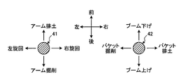
- FIG. 3 is an explanatory diagram showing the relationship between the operation direction of the operation lever and the movement of the work implement or the upper swing body.
- FIG. 4 is an explanatory diagram for explaining excavation and loading work by a hydraulic excavator.
- FIG. 5 is a time chart for explaining the process for counting the number of times of loading.
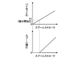
- FIG. 6 is a diagram showing the relationship between the spool stroke, the pilot pressure, and the spool opening.
- FIG. 7 is a time chart showing the reset processing of the time integral value at the time of excavation operation.
- FIG. 1 is a perspective view showing a schematic configuration of a hydraulic excavator according to an embodiment of the present invention.
- FIG. 2 is a block diagram showing a configuration of the hydraulic excavator shown in FIG.
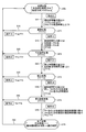
- FIG. 8 is a state transition diagram showing basic measurement processing of the number of times of loading.
- FIG. 9 is a time chart for explaining the time integrated value holding time during the excavation operation.
- FIG. 10 is a time chart showing a relationship between an erroneous determination and a normal determination of the next return turning operation when an excavation operation is performed during the return turning operation.
- FIG. 11 is a graph showing changes in pilot pressure over time.
- FIG. 12 is a state transition diagram illustrating a basic measurement process of the number of times of loading including a deemed counting process and an auxiliary work operation excluding process.
- FIG. 13 is a state transition diagram showing a basic measurement process of the number of times of loading including an assumed counting process, an exclusion process of incidental work operations, and an exclusion process according to the external state.
- FIG. 14 is a block diagram showing a detailed configuration of the monitor.
- FIG. 15 is a diagram illustrating a display example of work management using the basic excavation loading time.
- FIG. 16 is a diagram illustrating a schematic configuration of a work management system including a hydraulic excavator.
- FIG. 1 and FIG. 2 have shown the whole structure of the hydraulic shovel 1 which is an example as a working machine.
- the hydraulic excavator 1 includes a vehicle main body 2 and a work implement 3.
- the vehicle main body 2 includes a lower traveling body 4 and an upper swing body 5.
- the lower traveling body 4 has a pair of traveling devices 4a.
- Each traveling device 4a has a crawler belt 4b.
- Each traveling device 4a travels or turns the excavator 1 by driving the crawler belt 4b with a right hydraulic traveling motor and a left hydraulic traveling motor (hydraulic traveling motor 21).
- the upper turning body 5 is provided on the lower traveling body 4 so as to be turnable, and turns when the turning hydraulic motor 22 is driven.
- the upper swing body 5 is provided with a cab 6.
- the upper swing body 5 includes a fuel tank 7, a hydraulic oil tank 8, an engine room 9, and a counterweight 10.
- the fuel tank 7 stores fuel for driving the engine 17.
- the hydraulic oil tank 8 stores hydraulic oil that is discharged from the hydraulic pump 18 to a hydraulic cylinder such as the boom cylinder 14, hydraulic equipment such as the swing hydraulic motor 22, and the hydraulic travel motor 21.
- the engine room 9 houses devices such as the engine 17 and the hydraulic pump 18.
- the counterweight 10 is disposed behind the engine chamber 9.
- the work machine 3 is attached to the front center position of the upper swing body 5 and includes a boom 11, an arm 12, a bucket 13, a boom cylinder 14, an arm cylinder 15, and a bucket cylinder 16.
- a base end portion of the boom 11 is rotatably connected to the upper swing body 5. Further, the distal end portion of the boom 11 is rotatably connected to the proximal end portion of the arm 12.
- the tip of the arm 12 is rotatably connected to the bucket 13.
- the boom cylinder 14, the arm cylinder 15, and the bucket cylinder 16 are hydraulic cylinders that are driven by hydraulic oil discharged from the hydraulic pump 18.
- the boom cylinder 14 operates the boom 11.
- the arm cylinder 15 operates the arm 12.
- the bucket cylinder 16 is connected to the bucket 13 via a link member, and can operate the bucket 13.
- the bucket 13 operates as the cylinder rod of the bucket cylinder 16 expands and contracts.
- the cylinder rod of the bucket cylinder 16 when excavating and scooping up earth and sand with the bucket 13, the cylinder rod of the bucket cylinder 16 is extended, the bucket 13 operates while rotating backward from the front of the excavator 1, and then the scooped earth and sand are discharged. At this time, the cylinder rod of the bucket cylinder 16 is contracted, and the bucket 13 operates while rotating forward from the rear of the excavator 1.
- the excavator 1 includes an engine 17 and a hydraulic pump 18 as drive sources.
- a diesel engine is used as the engine 17, and a variable displacement hydraulic pump (for example, a swash plate hydraulic pump) is used as the hydraulic pump 18.
- a hydraulic pump 18 is mechanically coupled to the output shaft of the engine 17, and the hydraulic pump 18 is driven by driving the engine 17.
- the hydraulic drive system drives the boom cylinder 14, the arm cylinder 15, the bucket cylinder 16, and the turning hydraulic motor 22 according to the operation of the operation levers 41 and 42 provided in the cab 6 provided in the vehicle body 2. Further, the hydraulic traveling motor 21 is driven in accordance with the operation of the traveling levers 43 and 44.
- the operation levers 41 and 42 are arranged on the left and right sides of an operator seat (not shown) in the cab 6, and the travel levers 43 and 44 are arranged in front of the operator seat.
- the operation levers 41 and 42 and the travel levers 43 and 44 are pilot-type levers, and a pilot pressure is generated according to the operation of each lever.
- the magnitudes of the pilot pressures of the operation levers 41 and 42 and the travel levers 43 and 44 are detected by the pressure sensor 55, and an output voltage corresponding to the magnitude of the pilot pressure is output as an electrical signal.
- An electric signal corresponding to the pilot pressure detected by the pressure sensor 55 is sent to the pump controller 31. Pilot pressure from the operation levers 41 and 42 is input to the control valve 20, and the hydraulic pump 18 and the boom cylinder 14, the arm cylinder 15, the bucket cylinder 16, and the swing hydraulic motor 22 are connected within the control valve 20. Control the opening of the main valve.
- the pilot pressure from the travel levers 43 and 44 is input to the control valve 20 to control the opening of the main valve that connects between the corresponding hydraulic travel motor 21 and the hydraulic pump 18.
- a fuel adjustment dial 29, a monitor 32, and a turning lock portion 33 are provided in the vicinity of the operator seat in the cab 6 and are easily operated by the operator.
- the fuel adjustment dial 29 is a dial (setting device) for setting the fuel supply amount to the engine 17.
- the set value of the fuel adjustment dial 29 is converted into an electrical signal and output to the engine controller 30.
- the fuel adjustment dial 29 may be incorporated in the display / setting unit 27 of the monitor 32 so that the fuel supply amount can be set by operating the display / setting unit 27.
- the monitor 32 is a display device and includes a display / setting unit 27 that performs various displays and settings.
- the monitor 32 has a work mode switching unit 28.
- the display / setting unit 27 and the work mode switching unit 28 include, for example, a liquid crystal panel and a switch.
- the display / setting unit 27 and the work mode switching unit 28 may be configured as a touch panel.
- the P mode and the E mode are modes for performing normal excavation and loading work. In the E mode, the output of the engine 17 is suppressed as compared with the P mode.
- the L mode is switched when an unillustrated hook is attached to, for example, a mounting pin for connecting the bucket 13 and the link member, and arm crane operation (lifting work) is performed to lift the load suspended by the hook.
- the L mode is a fine operation mode in which the engine speed is controlled to keep the output of the engine 17 constant and the work implement 3 can be moved slowly.
- the B mode is a mode that can be switched when attaching a breaker for crushing rocks or the like as an attachment instead of the bucket 13, so that the output of the engine 17 can be kept constant by suppressing the engine speed.
- the ATT mode is a spare mode that can be switched when a special attachment such as a crusher is attached instead of the bucket 13, and hydraulic equipment is controlled.
- the discharge amount of hydraulic oil of the hydraulic pump 18 is controlled. Mode.
- a work mode signal generated when the operator operates the work mode switching unit 28 is sent to the engine controller 30 and the pump controller 31.
- the turning lock unit 33 is a switch for turning on / off a turning parking brake (not shown).
- the turning parking brake applies a brake to the turning hydraulic motor 22 so that the upper turning body 5 does not turn.
- an electromagnetic solenoid (not shown) is driven, and a brake for pressing a rotating component of the turning hydraulic motor 22 is operated in conjunction with the movement of the electromagnetic solenoid.
- the turning parking brake ON / OFF signal in the turning lock unit 33 is also input to the pump controller 31 by monitoring.
- the engine controller 30 includes an arithmetic device such as a CPU (numerical arithmetic processor) and a memory (storage device).
- a fuel injection device 80 is attached to the engine 17.
- a common rail fuel injection device is used as the fuel injection device 80.
- the engine controller 30 generates a control command signal based on the set value of the fuel adjustment dial 29, sends a signal to the fuel injection device 80, and adjusts the fuel injection amount to the engine 17.
- the pump controller 31 receives signals transmitted from the engine controller 30, the monitor 32, the operation levers 41 and 42, and the travel levers 43 and 44, controls the tilt of the swash plate angle of the hydraulic pump 18, and controls from the hydraulic pump 18. A control command signal for adjusting the discharge amount of the hydraulic oil is generated.
- the pump controller 31 receives a signal from a swash plate angle sensor 18 a that detects the swash plate angle of the hydraulic pump 18. When the swash plate angle sensor 18a detects the swash plate angle, the pump displacement of the hydraulic pump 18 can be calculated.
- the pump controller 31 receives signals transmitted from the monitor 32, the pressure sensors 55 attached to the operation levers 41 and 42 and the travel levers 43 and 44, and the turning lock unit 33, and determines the work amount of the excavator 1. Process to measure. Specifically, processing is performed to calculate the number of excavation loading operations (hereinafter referred to as the number of loadings) and the basic excavation loading time, which are the basis for measuring the work amount. Details of the number of times of loading and the basic excavation loading time will be described later.
- the pump controller 31 includes an operation state detection unit 31a, a time integration unit 31b, a determination unit 31c, a counting unit 31d, a mode detection unit 31e, a travel operation detection unit 31f, and a turning lock detection unit 31g.
- the operation state detection unit 31a receives a signal output from the pressure sensor 55 and detects a pilot pressure that is a physical quantity output according to the operation of the operation levers 41 and 42.
- the pilot pressure that drives the bucket cylinder 16 and the swing hydraulic motor 22 is detected in order to capture that excavation and loading work is being performed.
- the physical quantity output in response to the operation of the operation levers 41 and 42 is used as the pilot pressure. This is because the operation levers 41 and 42 are pilot-type levers.
- the physical quantity is an electric signal such as a voltage output by a potentiometer or a rotary encoder.
- the stroke amount of each cylinder is directly detected by a stroke sensor attached to the cylinder rods of the boom cylinder 14, the arm cylinder 15 and the bucket cylinder 16, for example, a rotary encoder.
- Data may be handled as a physical quantity that is output according to the operation of the operation levers 41 and 42.
- a stroke sensor that detects the operation amount of the valve spool may be used to detect the stroke amount of the spool, and the detected data may be handled as a physical quantity that is output according to the operation of the operation levers 41 and 42.
- a flow rate sensor that detects the flow rate of hydraulic oil from the main valve may be used, and this flow rate may be used as a physical quantity.
- an angle sensor is provided on each rotation shaft of the work machine 3 such as the boom 11, the arm 12, and the bucket 13, and an angle sensor that detects the angle of the upper swing body 5 is provided. The operating angle of the upper swing body 5 may be detected, and the detected data of the operating angle of the work machine 3 and the upper swing body 5 may be handled as physical quantities output in accordance with the operation of the operation levers 41 and 42.
- the bucket 13 and the upper swing body 5 are referred to as an excavation and loading mechanism unit.
- the time integration unit 31b calculates a time integration value obtained by integrating the pilot pressure with time.
- the determination unit 31c associates the time integration value with a predetermined operating angle of the excavation loading mechanism unit associated with the operation of the operation levers 41 and 42, and when the time integration value is equal to or greater than the predetermined integration value, It is determined that the levers 41 and 42 have been operated.
- the counting unit 31d performs the operation of the excavation and loading mechanism unit performed in the predetermined order as one time.
- the number of operations of the excavation and loading mechanism section (the number of excavation and loading operations, that is, the number of loading operations) is counted.
- This series of operations of the excavation and loading mechanism section is excavation and loading work, and is an operation performed in the order of excavation, going-turning, earth removal, and return-turning.
- the operation performed in this order is used as a pattern for excavation loading work, and the number of times this pattern is performed is counted as the number of loading operations. Details of excavation and loading work will be described later.
- the mode detection unit 31e detects the work mode instructed to be switched by the work mode switching unit 28.
- the traveling operation detection unit 31f determines whether or not the traveling operation by the traveling levers 43 and 44 has been performed based on a signal indicating the pilot pressure output from the pressure sensor 55.
- the turning lock detection unit 31g detects whether or not the turning lock unit 33 is turning on the turning lock.
- the operation state detector 31a detects whether or not the pressure sensor 55 that detects the pilot pressure is in an abnormal state.
- the abnormal state is, for example, a case where the output voltage value of the pressure sensor 55 outputs an abnormal voltage value out of the normal voltage value range for several seconds. Accordingly, the disconnection of the pressure sensor 55 is also in an abnormal state.
- the operation levers 41 and 42 are disposed on the left and right sides of an operator seat (not shown) in the cab 6, the operation lever 41 is disposed on the left hand side when the operator is seated on the operator seat, and the operation lever 42 is , Arranged on the right hand side opposite to that.
- the swing hydraulic motor 22 can be driven to turn the upper swing body 5 left and right.
- the arm cylinder 15 can be driven to extend and retract to perform arm earthing and arm excavation.
- the arm earth removal is an operation performed when the tip of the arm 12 is moved while rotating forward from the rear of the hydraulic excavator 1 and the earth and sand contained in the bucket 13 is discharged.
- the arm excavation is an operation performed when the tip of the arm 12 is moved while rotating from the front to the rear of the excavator 1 and the bucket 13 scoops the earth and sand.
- the operation lever 42 is tilted left and right in the figure, the bucket cylinder 16 can be driven to perform bucket excavation and bucket soiling.
- the boom cylinder 14 can be driven to lower the boom and raise the boom.
- the operation levers 41 and 42 can be tilted over the entire circumference.
- the arm can be removed while turning left.
- the traveling lever 43 can perform traveling right forward and traveling right backward according to an operation.
- the traveling lever 44 can perform traveling left forward and traveling left backward in accordance with an operation. That is, if only the traveling lever 43 is operated, the right crawler belt 4b is driven, if only the traveling lever 44 is operated, the left crawler belt 4b is driven, and if the traveling levers 43 and 44 are operated simultaneously, the left and right crawler belts 4b are driven. Drive simultaneously.
- the relationship between the operation direction of the operation lever shown in FIG. 3 and the movement of the work implement 3 or the upper swing body 5 is shown as an example. Therefore, the relationship between the operation direction of the operation lever and the movement of the work implement 3 or the upper swing body 5 may be different from that in FIG.
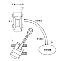
- FIG. 4 shows a case where the dump truck 50 is waiting on the left side of the excavator 1. That is, this is a case where the dump truck 50 stands by on the side close to the cab 6 when the excavator 1 is directed in a direction in which the excavation position E1 is located.
- the excavation and loading operation is a series of operations performed in the order of excavation, going-turning, earth removal, and return-turning.
- the operation lever 42 is tilted to the left at the excavation position E1 to excavate soil and the like with the bucket 13.
- the operation lever 41 is tilted to the left and the operation lever 42 is tilted to the rear side to the position of the dump truck 50 that carries the earth and sand to be loaded.
- the boom 11 is raised while turning.
- the operation lever 42 is tilted to the right at the position of the dump truck 50 to remove earth and sand scooped in the bucket 13.
- the operation lever 41 in the return turn, is tilted to the right from the position of the dump truck 50 to the excavation position E1, and the operation lever 42 is further tilted to the front side, while turning the upper swing body 5 to the right.
- the boom 11 is lowered.
- the excavation position E1 is located on the left side of the dump truck 50, the going turn is a right turn and the return turn is a left turn.
- the dump truck 50 stands by on the side opposite to the operator cab 6. That is, the going turn is an operation for turning from the excavation position E1 to the earth discharging position of the dump truck 50, and the return turning is an operation for turning from the earth discharging position to the excavation position E1.
- the predetermined integral value is determined by the excavation and loading mechanism unit that is the bucket 13 or the upper swing body 5 with each operation. This corresponds to the case of moving by an angle of.
- the predetermined angle that is, the predetermined operating angle corresponds to an angle at which the excavation and loading mechanism unit operates when each operation is performed.
- an angle corresponding to the movement of the bucket 13 when excavation or soil removal is performed is a predetermined operation angle.
- an angle corresponding to the turning movement at the time of excavation loading work is a predetermined operating angle.
- These predetermined operating angles are the same value even in the hydraulic excavators 1 having different vehicle grades, and the time integration values corresponding to the predetermined operating angles differ depending on the vehicle grades. Therefore, even if the excavator 1 has different vehicle grades, the time integration value obtained by time integration of the pilot pressure and the excavation loading mechanism that accompanies the operation of the operation levers 41 and 42 are obtained for each vehicle case. As long as the correspondence with the predetermined operating angle of the part is determined, the number of loadings for each vehicle case can be measured.
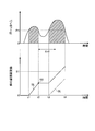
- the pilot pressure generated when the operation lever 42 is tilted to the left to move the bucket 13 is detected, and this pilot pressure is equal to or higher than the integration start pressure P1.
- time integration of the pilot pressure is started, and it is determined that excavation operation has been performed when the time integration value becomes S1 or more.
- This time integral value S1 is the excavation time integral value S1, and corresponds to a predetermined operating angle of the bucket 13 when excavation is performed.
- time integration of each pilot pressure is started when each pilot pressure becomes equal to or higher than the integration start pressure P1.
- the pilot pressure generated when the operation lever 41 is tilted to the left or right is detected to obtain the time integral value S2 or S4.
- the pilot pressure generated when the operating lever 42 is tilted to the right is detected, and the time integrated value S3 is obtained.
- the time integral value S2 for the outgoing turn, the time integral value S3 for the earth removal, and the time integral value S4 for the return turn also correspond to the predetermined operating angles of the upper swing body 5, the bucket 13, and the upper swing body 5, respectively. .
- the fact that the time integration unit 31b has obtained each of the time integration values S1 to S4 means that the bucket 13 or the upper swing body 5 has operated over a predetermined operating angle.
- the loading number is counted as one and the loading number is cumulatively calculated.
- the information on the accumulated number of times of loading is transmitted to the monitor 32, for example, and the monitor 32 measures the amount of work.
- the measurement of the work amount is obtained by multiplying the cumulative number of times of loading by a preset bucket capacity. This result is displayed on the display unit of the monitor 32, for example.
- the operation time required for a series of excavation and loading operations is accumulated, and the accumulated operation time is output as the basic excavation loading time, for example, to the monitor 32, and the display / setting unit of the monitor 32 is displayed. 27.
- the amount of work may be measured using a computer or a portable computer installed outside the hydraulic excavator 1, for example, in a remote place. In other words, information on the accumulated number of loadings is transmitted to the outside wirelessly or by wire, the accumulated number of loadings is received by a receiving device provided outside, and the bucket capacity stored in the external storage device is used. The amount of work may be measured.
- FIG. 6 is a diagram showing changes in the pilot pressure and the size of the spool opening with respect to the spool stroke.
- the spool stroke of the main valve (not shown) is zero. For this reason, time integration is started when the pilot pressure becomes equal to or higher than the above-described integration start pressure P1.
- FIG. 7 is a time chart showing the reset processing of the time integral value at the time of excavation operation.
- the upper part of FIG. 7 shows the change of the pilot pressure with time, and the shaded area corresponds to the time integrated value of the pilot pressure.
- the lower diagram of FIG. 7 shows changes in the spool opening over time, and the hatched portion corresponds to the integral value of the spool opening area. As shown in FIG.
- this reset process is based on the time when the pilot pressure becomes lower than the integral start pressure P1, but after the pilot pressure becomes lower than the integral start pressure P1 in order to eliminate the influence of noise and the like.
- the operation is performed after a predetermined time ⁇ t2. That is, the integration start pressure P1 is an integration start pressure and a predetermined operation end value that is a threshold for determining that the operation has ended.
- the predetermined time ⁇ t2 is provided for the excavation operation and the soil removal operation, and the value is different for each operation.
- the state stay time TT is set to 0, and the turning direction flag FA is set to 0.
- the state shifts to the excavation state ST1 (S01).
- Condition 01 is that the elapsed time after the excavation time integrated value is S1 or more, the pilot pressure is P2 or less, and the pilot pressure is P2 or less is ⁇ TS or more.
- the pilot pressure P2 is a threshold value used for determining that the excavation operation is finished and the state transition of FIG. 8 is possible. Details of the state transition diagram of FIG. 8 will be described later.
- FIG. 9 is a time chart for explaining the time integration value holding time during excavation operation.
- a full lever operation that tilts the operation lever 42 to a tiltable stroke may not be performed. That is, in order to excavate, the excavation operation may be performed while tilting or raising the operation lever 42.
- Intermittent lever operation may occur, such as going up or down at the border. Therefore, the elapsed time ⁇ t2 (time integrated value holding time) after the pilot pressure becomes equal to or less than the integration start pressure P1 is set to a sufficiently large value corresponding to the excavation operation, and intermittent excavation operation is performed as one excavation operation. Can be determined as.
- the time integration process is continued if the time integration value holding time ⁇ t2 has not elapsed. Since the turning operation is basically a full lever operation, when the integration start pressure P1 or less is reached, the time integration process is terminated and the held time integration value is erased (reset).
- the lower part of FIG. 9 shows the change in the magnitude of the excavation time integrated value over time.
- the time integration is reset immediately at time t2 when the pilot pressure becomes equal to or lower than the integration start pressure P1
- the broken line extending upward from time t2 in the lower diagram of FIG. Only the integrated excavation time value of the size indicated by the intersection SS with the solid line SL shown is obtained.
- the excavation time integrated value as shown by the solid line SL in the lower diagram of FIG. 9 should be obtained, and it should be determined that the excavation operation has been performed when the excavation time integrated value exceeds S1. is there.
- the next excavation operation may be entered during the return turning operation, and when the end of the excavation operation determination is performed with the time integration value, the next return turning operation may be erroneously determined. That is, the bucket excavation operation of the operation lever 42 is performed while returning the operation lever 41 and performing an operation for turning after the earth has been discharged. In such a case, the excavator 1 moves in such a manner that the bucket 13 is excavated while the upper swing body 5 returns and swivels in the swiveling direction.
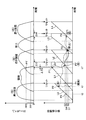
- FIG. 10 is a time chart showing a relationship between an erroneous determination and a normal determination of the next return turning operation when an excavation operation is performed during the return turning operation. In the upper diagram of FIG.
- the pilot pressure PP1 is shown, but this has the same meaning only by changing the notation of the pilot pressure P1 described above. Further, although the pilot pressure PP2 is shown in the upper diagram of FIG. 10, it has the same significance only by changing the notation of the pilot pressure P2 described above. Curves L0 to L4 shown in the lower part of FIG. 10 are shown as straight lines for convenience. Depending on how the lever is operated, the time integration value may or may not increase monotonically in a linear function. In the following description, it is expressed as a curve.
- the time integral value of the curve L0 is obtained in the first return turning operation, and the point P0 (time point t0) on the curve L0 is obtained.
- the time integral value of the curve L1 is obtained, and at the point P1 (time point t1) on the curve L1, the time integral value reaches S1. Therefore, the end of the excavation operation is determined.
- the pump controller 31 acquires the time integral value of the next turn (going turn), but since the pilot pressure of the return turn is not lower than PP1, the time integral value of the curve L0 is not reset.
- the time integral value of the point P2 on the curve L0 is acquired as the time integral value of the going turn.
- it may be a right turn or a left turn
- in the case of a return turn when the outgoing turn is a right turn
- a pilot pressure for turning right or a pilot pressure for turning left is generated.
- the pressure sensor 55 for detecting the pilot pressure for the right turn and the pressure sensor 55 for detecting the pilot pressure for the left turn are provided.
- the turn direction flag FA is set in a signal output from the pressure sensor 55 that detects a right turn pilot pressure
- a left turn lever operation is performed, a left turn The turning direction flag FA is set in a signal output from the pressure sensor 55 that detects the pilot pressure of the rotation.
- the left turn or the right turn is performed after excavation depends on the positional relationship among the excavation position E1, the hydraulic excavator 1, and the dump truck 50. Therefore, it is assumed that the left and right are not handled separately in the basic measurement processing of the number of times of loading with respect to the turning turn.
- the turning direction is always opposite between the going turn and the returning turn, the above rule is provided.
- the pump controller 31 attempts to acquire a time integration value of the soil removal operation that is an operation after the turn. Therefore, although the time integral value of the normal going-turning exists in the curve L2, the state transition to the going-turning is skipped, and further the soil removal operation is performed, and the time integration value on the curve L3, which is the time integral value of the soil removal operation. Since the time integration value has reached S3 at the point P3, the end of the soil removal operation is determined. The pump controller 31 goes further to acquire the time integral value of the return turning operation.
- the reason why this erroneous determination occurs is that the time integral value of the previous turning operation remains without being reset immediately after the time t1 when the end determination of the excavation operation is performed at the point P1. Therefore, in this embodiment, the end determination of the excavation operation is delayed, and the time integration value of the return turning operation is reset when the end determination of the excavation operation is completed.
- the pilot pressure becomes PP2 or less, and further, from the time when the pilot pressure becomes PP2 or less in order to eliminate the influence of noise or the like.
- the end of the excavation operation is determined after a predetermined time ⁇ TS has elapsed.
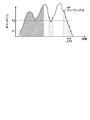
- the predetermined time ⁇ TS is, for example, twice the sampling period (see FIG.
- FIG. 11 is a graph showing changes in pilot pressure over time. That is, as shown in FIG. 11, the predetermined time ⁇ TS is twice the period for sampling the pilot pressure, and is a time obtained by doubling the time between two consecutive sampling points SP. By doing in this way, the end determination of excavation operation is not performed when the pilot pressure which fell instantaneously was detected, and erroneous determination is prevented. As described above and with reference to FIG. 9, when the time integrated value holding time ⁇ t2 elapses from the time t1 ′ when the pilot pressure generated by the excavation operation becomes equal to or less than the integration start pressure PP1, the time integration of the excavation Processing is reset. Although it is preferable to provide the predetermined time ⁇ TS as in the present embodiment, it is not necessarily provided.
- the end of the soil removal operation is determined. Furthermore, since the time integral value of the return turn reaches S4 at the point P4 of the curve L4, the end determination of the return turn can be normally performed.
- the state stay time TT of the excavation state ST1 is measured.
- the state stay time TT is T1.
- the turning state ST2 S12
- the turning time integral value is S2 or more.
- the turning direction of the going turn may be either left or right.
- the pilot pressure generated according to the tilting direction of the operation lever 41 as described above, that is, the electric signal output from the pressure sensor 55 is used to make a right turn. It is determined whether the vehicle is turning left.
- the turning direction flag FA is set to the right, and if turning left, the turning direction flag FA is set to the left. Moreover, the state stay time TT is reset to 0 at the time of transition to the going-turning state ST2.
- the state stay time TT of the turn turning state ST2 is counted.
- the state stay time TT is T2.
- the soil removal time integrated value is S3 or more, and the left-right turn time integrated value is less than ⁇ S.
- the state stay time TT is reset to 0 at the time of transition to the soil removal state ST3. The reason why the condition 23 is set as to whether or not the left / right turn time integration value is less than ⁇ S will be described. When earth is being dumped, it should not turn.
- the left / right turn time integral value is a time integral value of pilot pressure generated by the right turn or left turn operation of the operation lever 41. It is possible to shift the state transition to the soil removal state ST3 by determining whether or not the turning is performed so that the left-right turn time integrated value exceeds a predetermined value ( ⁇ S) in the going-turn state (ST2). It is judged whether it can be done. If the left / right turning time integration value exceeds ⁇ S, an operation of turning while discharging the soil is assumed, for example, an operation in which the earth and sand are scattered within a predetermined range. In this case, in the initial state ST0 (S20) so that the count of the number of loadings is not erroneously determined.
- the state staying time TT of the earthing state ST3 is counted.
- the state stay time TT is T3.
- the turning time integral value is S4 or more.
- the turn time integral value is the time integral value of the left turn when the turn direction is opposite to the turn direction, that is, the turn direction flag FA is right, and the right turn when the turn direction flag FA is left. It is a condition that the time integral value of. Further, the state stay time TT is reset to 0 at the time of transition to the return state ST4.
- condition 30 If the state stay time T3 in the soil removal state ST3 is equal to or longer than the predetermined time TT3 (condition 30), the process proceeds to the initial state ST0 (S30).
- the state stay time TT of the return turning state ST4 is counted.
- the state stay time TT is T4.
- the process proceeds to the completion state ST5 (S45).
- the condition 45 is that when the turning direction flag FA is right, the turning time integrated value of left turning is 0, when the turning direction flag FA is left, the turning time integrated value of right turning is 0, and
- the state stay time T4 is equal to or longer than the predetermined time TT4.
- condition 40 If the state stay time T4 in the return turning state ST4 is less than the predetermined time TT4 (condition 40), the process proceeds to the initial state ST0 (S40).
- the number of loadings is counted only once and cumulatively added. If there is a number of loadings accumulated in the past, 1 is added to the number of loadings.
- the obtained loading number is stored in a storage device (not shown) provided in the pump controller 31.
- the pump controller 31 incorporates a timer function (not shown), and measures the time required from the start of excavation to the completion of return turning when the number of times of loading is counted as one. That is, when it is detected that the pilot pressure of excavation has exceeded a predetermined integral start pressure P1 as shown in FIG.
- the timer starts counting, after the going turn, the earth is discharged, the return turn is performed.
- the process shifts to the completion state ST5 the timer count is ended, and the time from the start to the end is obtained as the basic excavation loading time.
- the obtained basic excavation loading time is stored in a storage device (not shown) provided in the pump controller 31. Thereafter, the process proceeds to the initial state ST0 (S50).
- the state transition transition condition shown in FIG. 12 is added, and a specific operation that may be performed during a series of excavation loading work operations is performed once. Deemed counting processing is performed.
- the no-operation time ⁇ t ⁇ after turning is set in advance.
- the process proceeds to the completion state ST5, and the loading number is counted once (S25).
- the condition 25 is that no operation time other than excavation or turning is ⁇ t ⁇ or more, and the deemed completion flag F ⁇ is 0, that is, the deemed counting process has never been performed.
- the non-operation time other than excavation or turning means that the bucket earthing no operation time, boom raising no operation time, boom lowering no operation time, arm excavation no operation time, arm excavation no operation time.
- the operation time is ⁇ t ⁇ or more.
- the reason for excluding the no-operation time for excavation or turning is that the operation may be performed by moving the bucket 13 in small increments when stopping during the turning operation or while stationary. This is because the bucket 13 clogged with earth and sand may naturally descend due to its own weight, and it is necessary to perform an operation (the operation lever 42 is tilted to the left side, that is, the bucket excavation side) to lift the lowered bucket 13. Because.
- the deemed counting process according to the condition 25 is necessary, for example, when the excavator 1 performs five excavation and loading operations in order to load the dump truck 50 with the earth and sand. That is, the count processing is necessary for the first (first) series of excavation and loading operations or the last (fifth) series of excavation and loading operations in five excavation and loading operations. Therefore, when the condition 25 is satisfied, the deemed completion flag F ⁇ is set to 1, and the condition 25 is based on the condition that the deemed completion flag F ⁇ is 0. That is, it is a condition that the assumed counting process has never been performed. If the earth removal operation is performed next, the deemed completion flag F ⁇ is set to 0.
- the no-operation time ⁇ t ⁇ after earthing is set in advance.
- the specific state such as the condition 35 is satisfied in the soil removal state ST3
- the process proceeds to the completion state ST5, and the loading count is cumulatively counted once (S35).
- the condition 35 is that the non-operation time other than excavation is equal to or longer than the no-operation time ⁇ t ⁇ after earth removal. That is, the count processing is performed when a specific state occurs in which the operation order of the excavation and loading mechanism section is stagnant and not advanced.
- the reason why the no-operation time for excavation is excluded is that there is a case where the operation of moving the bucket in small increments is performed during the stationary state as described above.
- incidental work may enter during a series of excavation and loading work in actual work.
- a soil removal operation may be performed immediately after the excavation operation, or a reverse turning operation may be performed immediately after the turning operation.
- This incidental work is a work in which the order of operations of the excavation and loading mechanism part constituting the series of excavation and loading work is different, and is an operation similar to the series of excavation and loading work. Therefore, in this embodiment, such incidental work is regarded as a specific state and is positively excluded to eliminate erroneous determination. That is, when a specific state in which the order of operations of the excavation and loading mechanism unit is skipped, that is, when an incidental work occurs, the incidental work exclusion process is performed so that the number of loadings is not counted.
- a condition 10a is added in which the soil removal time integrated value is equal to or greater than the soil removal time integrated value S3a after excavation in the excavation state ST1.
- the process proceeds to the initial state ST0 (S10).
- the soil removal time integration value S3a after excavation is a preset value.
- a condition 20a is added in which the turning time integrated value in the direction opposite to the turning direction indicated by the current turning direction flag FA is equal to or greater than the value S4a in the going turning state ST2.
- the process proceeds to the initial state ST0 (S20).
- the turning time integrated value S4a after turning is a value set in advance.
- the operation mode is a mode in which a series of excavation and loading operations are not performed, if this is not taken into consideration, the number of times of loading is counted as long as the operation of the operation levers 41 and 42 is detected by the pilot pressure. There is.
- the turning lock unit 33 when the turning lock unit 33 is operated to lock the upper turning body 5, there is no intention to turn, but if this is not taken into consideration, the operation of the operation levers 41 and 42 is controlled by the pilot pressure. As long as it detects, the number of loading may be counted.
- These states are states in which the operation of the excavation and loading mechanism part related to the operation of a series of excavation and loading work is possible, and a specific operation unrelated to the operation of the series of excavation and loading mechanism parts is performed (Specific operation state). In this specific operation state, it is necessary to reset the counting process of the number of times of loading to prevent erroneous determination.
- an exclusion condition is further added as shown in the state transition diagram shown in FIG.
- the operator may accidentally touch the traveling levers 43 and 44 without intending to perform the traveling operation.
- resetting the process of counting the number of times of loading results in an erroneous determination.
- whether or not the vehicle is in the traveling operation state is determined by acquiring the traveling time integral value of the pilot pressure of the traveling levers 43 and 44 as in the case of the excavation, turning and earthing operations. Is determined to be in the traveling operation state when the traveling time integrated value S ⁇ is greater than or equal to.
- the travel time integration value S ⁇ for travel determination is a preset value.
- Condition 01b is that the travel time integrated value is less than the travel time integrated value S ⁇ for travel determination, and the work mode is not set to the ATT mode, the B mode, or the L mode (ATT / B / L mode).
- Signal is OFF)
- the pressure sensor 55 for detecting the pilot pressure is not abnormal (the pilot pressure sensor abnormality flag is OFF)
- the upper swing body 5 can be turned without the turning lock portion 33 being operated (the turning lock flag). Is OFF).
- conditions 10, 10a and 20 and 20a are OR conditions
- conditions 10b, 20b, 30b and 40b are added as OR conditions.
- Conditions 10b, 20b, 30b, and 40b are set such that the travel time integral value is equal to or greater than the travel time integral value S ⁇ for travel determination, or the work mode is set to either ATT / B / L mode (ATT / B / L mode signal is ON), or an abnormality has occurred in the pressure sensor 55 that detects the pilot pressure (the pilot pressure sensor abnormality flag is ON), or the turning lock unit 33 is operated and the upper turning body 5 is The turning is impossible (the turning lock flag is ON).
- the specific operation state described above instead of resetting the counting process of the number of loading as described above, in the specific operation state, for the time being, cumulative addition of the number of loading, The number of occurrences of the specific operation state may be separately counted. Then, an operation for subtracting the number of occurrences of the specific operation state from the obtained number of loadings, that is, a correction process may be performed to obtain the correct number of loadings. This subtraction process is performed, for example, after the daily work is finished, so that the obtained correct loading number can be used for the daily work management. Even if there is a specific operation state as described above, the erroneous determination of the number of loadings can be prevented by resetting or correcting the counting process of the number of excavation loading operations.
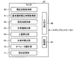
- the monitor 32 acquires at least the number of times of loading and the basic excavation loading time from a storage device (not shown) of the pump controller 31 described above. As shown in FIG. 14, the monitor 32 includes a loading number acquisition unit 60, a basic excavation loading time acquisition unit 61, a default value setting unit 62, a work amount calculation unit 63, a soil amount calculation unit 64, and a work rate calculation unit 65. An input / output unit 66 and a storage unit 67. Further, the monitor 32 includes an operator identification unit 70 and a setting change unit 71.
- the default value setting unit 62 stores in the storage unit 67 data indicating the bucket capacity, the number of dump trucks, and the dump truck load capacity of the excavator 1 that are input and set from the input / output unit 66.
- the dump truck load is the amount of earth and sand that can be loaded per dump truck. In the present embodiment, the case where earth and sand are loaded onto the dump truck 50 has been described. However, instead of the dump truck 50, when the excavator 1 loads earth and sand on a transport ship having a loading platform used for dredging work at a port. In addition, work management processing as described below can be executed.
- the storage unit 67 holds the loading capacity of the carrier carrier and the number of carrier ships.
- work management processing can be executed by storing necessary data in the storage unit 67 when excavating and loading soil or the like on a train or a carriage instead of the dump truck 50. That is, this embodiment can be applied when loading earth and sand into various collection bodies such as the dump truck 50, a transport ship, a train, and a carriage.
- the work amount calculation unit 63 calculates a work amount obtained by adding the bucket capacity to the number of loadings acquired by the loading number acquisition unit 60, and holds the obtained work amount in the storage unit 67, for example, every day.
- the soil volume calculation unit 64 calculates a soil volume obtained by multiplying the number of dump trucks by the dump truck load, and holds the determined soil volume in the storage unit 67, for example, every day.
- the work rate calculation unit 65 calculates a value obtained by dividing the amount of soil by the work amount as a work rate, and holds the obtained work rate in the storage unit 67, for example, every day.
- the work volume is regarded as the sum of soil volume and counted work.
- the counted work means a work that is not an actual excavation and loading work by the excavator 1.
- the counted work means a work that is not an actual excavation and loading work by the excavator 1.
- the bucket 13 is operated without actually excavating earth and sand and the upper swing body 5 is turned, such an operation is determined as one excavation and loading operation (the number of times of loading).
- the number of loadings acquired by the loading number acquisition unit 60 is greater than the number of loadings corresponding to the amount of soil.
- the work amount and the soil amount may be exactly the same, but the work amount otherwise is a larger value than the soil amount. Therefore, if the work rate is obtained, it is possible to grasp the ratio of the counted work, and conversely, the ratio of the excavation and loading work.
- the monitor 32 for example, graphs each data such as the work amount, the soil amount, and the work rate, for example, every day and outputs the graph from the input / output unit 66.
- a graph using each data may be displayed on the display / setting unit 27 of the monitor 32.
- the monitor 32 may output each data such as the work amount, the soil amount, and the work rate to the outside of the excavator 1.
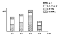
- the monitor 32 uses, for example, the basic excavation loading time acquired by the basic excavation loading time acquisition unit 61, the moving body information such as the traveling time and idling time obtained from the engine controller 30, etc., for example, FIG. As shown, the ratio of the excavation loading work time to the operating time of the excavator 1 is displayed and output every day.
- Each data explained above work volume, soil volume, work rate, ratio of excavation loading work time to working time of hydraulic excavator 1 is obtained outside hydraulic excavator 1 by a work management system as described later. Also good.
- each data required by the excavator 1 such as loading count, basic excavation loading time, traveling time, idling time, and operating time is externally wired or wirelessly from the storage device (not shown) of the input / output unit 66 or the pump controller 31.
- the ratio of the excavation loading work time to the amount of soil, work load, work rate, and operation time may be obtained by a computer provided outside and graphed and displayed on a display device connected to the computer.
- a mobile terminal may be used instead of the computer provided outside, and a display device of the mobile terminal may be used instead of the display device.
- FIG. 15 shows the daily excavation loading time ratio of a certain excavator 1, but not limited to this, the excavation loading time ratio is similarly obtained for a plurality of excavators 1 and compared for each excavator. You can also
- the operator identification unit 70 identifies operator identification information (hereinafter referred to as identification information), and associates the identified identification information with the number of loadings and basic excavation loading time for each operator and causes the storage unit 67 to hold them.
- identification information operator identification information
- the excavator 1 may be equipped with an immobilizer device.
- the engine of the excavator 1 can be started by the ID key in which individual identification information is stored.
- the immobilizer device reads the identification information of the ID key, the identification information is associated with the number of loadings for a predetermined period, for example, one day, and the associated information (number of loadings for each operator) is associated with the input / output unit 66.
- the work amount management for each operator can be performed for the one hydraulic excavator 1. Further, if it is set so that a plurality of hydraulic excavators 1 can be started with a single ID key, vehicle identification information data for identifying each vehicle of the plurality of hydraulic excavators 1, an ID key By outputting the identification information and the data of the number of loadings to the outside, it is possible to manage how much work is performed by which one operator with which hydraulic excavator.
- the above-described operator is provided with an ID number identification device for individually identifying an operator by inputting an individual ID number from the input / output unit 66 of the monitor 32 without using an immobilizer device, and an ID card reader. May be individually recognized and the above management may be performed.
- a fingerprint authentication device may be used as a device for individually recognizing an operator. That is, by providing the operator identification unit 70, the operator's work management can be performed.
- the setting change unit 71 can change various setting values (parameters) necessary for determining a series of excavation loading operations such as the time integration values S1 to S4 and the integration start pressure P1.
- the setting change unit 71 uses an external communication device capable of wireless or wired communication, and can change various setting values from the outside via the input / output unit 66. Note that various setting values may be changed via the input / output unit 66 using an input unit such as a switch provided in the display / setting unit 27 of the monitor 32.
- the setting changing unit 71 can change various setting values (parameters) such as the integration start pressure P1 by teaching for each work site or operator. Specifically, the bucket excavation operation is actually performed, and the bucket is operated from the excavation start posture to the excavation end posture. A predetermined memory button (not shown) is operated in the excavation start posture, and a predetermined memory button (not shown) is further operated in the excavation end posture. As a result, the time integrated value S1 of the pilot pressure at the time of each operation generated between the operation of the memory button is acquired, and this time integrated value is used as a set value.
- This memory button may be provided on the operation levers 41 and 42 or on the monitor 32. Further, other setting values can be set by the same teaching.
- FIG. 16 is a diagram illustrating a schematic configuration of a work management system including the hydraulic excavator 1.
- a plurality of mobile bodies such as hydraulic excavators 1 are geographically dispersed, and each hydraulic excavator 1 and management server 104 are connected to an external communication device such as a communication satellite 102, a ground station 103, and a network N such as the Internet. Communication connection is established via The network N is connected to a work management server 105 and a user terminal 106 which are servers of an administrator of the excavator 1.
- the excavator 1 shows the operation status such as the work information including the number of loadings and the basic excavation loading time described above, the position information and operating time of the excavator 1, travel time, idling time, vehicle identification information, and operator identification information.
- the mobile body information that is vehicle information including the information is transmitted to the management server 104.
- the management server 104 transfers the above-described work information and moving body information to the corresponding work management server 105 for each manager.
- the hydraulic excavator 1 has a moving body monitoring device 110, and the moving body monitoring device 110 is connected to a GPS sensor 116 and a transceiver 117.
- the GPS sensor 116 detects its own position based on information sent from a plurality of GPS satellites 107 via the antenna 116a, generates self-position information, and the mobile monitoring device 110 acquires this self-position information.
- the transceiver 117 is communicably connected to the communication satellite 102 via the antenna 117 a and performs information transmission / reception processing between the mobile monitoring device 110 and the management server 104.
- the work management server 105 has the same configuration and function as the monitor 32.
- the input / output unit 66 of the monitor 32 corresponds to the user terminal 106. Therefore, by accessing the work management server 105 from the user terminal 106, work management similar to the monitor 32 can be performed, and a wide range of work management can be performed. In other words, fleet management can be performed at a location away from the work site with respect to work progress, work efficiency, and the like.
- the work management server 105 does not have to have the same configuration and function as the monitor 32, and the monitor 32 may have the configuration and function shown in FIG.
- the setting change of various setting values can be performed on the setting change unit 71 of the monitor 32 via the work management server 105 and the management server 104 by the user terminal 106 accessing the work management server 105.
- a part of the configuration and functions of the monitor 32 may be provided on the management server 104 or the work management server 105 side.
- the hydraulic excavator 1 has a satellite communication function, but is not limited thereto, and may be various communication functions such as a wireless LAN communication function and a mobile communication function. That is, the excavator 1 has an external communication function.
- a wire for data communication is connected to the excavator 1 so that the external communication function is achieved by wire.
- a possible connector may be provided, and the work information and the moving body information may be downloaded via the wire.
Landscapes
- Engineering & Computer Science (AREA)
- Mining & Mineral Resources (AREA)
- Civil Engineering (AREA)
- General Engineering & Computer Science (AREA)
- Structural Engineering (AREA)
- Mechanical Engineering (AREA)
- Physics & Mathematics (AREA)
- General Physics & Mathematics (AREA)
- Operation Control Of Excavators (AREA)
- Component Parts Of Construction Machinery (AREA)
- Machine Tool Sensing Apparatuses (AREA)
Priority Applications (5)
| Application Number | Priority Date | Filing Date | Title |
|---|---|---|---|
| US14/438,980 US9783952B2 (en) | 2012-11-20 | 2013-11-12 | Working machine and method of measuring work amount of working machine |
| DE112013005544.9T DE112013005544T5 (de) | 2012-11-20 | 2013-11-12 | Arbeitsmaschine und Verfahren zum Messen einer Arbeitsleistung einer Arbeitsmaschine |
| CN201380058762.0A CN104781477B (zh) | 2012-11-20 | 2013-11-12 | 作业机械以及作业机械的作业量计量方法 |
| IN3938DEN2015 IN2015DN03938A (ko) | 2012-11-20 | 2013-11-12 | |
| KR1020157012094A KR101747010B1 (ko) | 2012-11-20 | 2013-11-12 | 작업 기계 및 작업 기계의 작업량 계측 방법 |
Applications Claiming Priority (2)
| Application Number | Priority Date | Filing Date | Title |
|---|---|---|---|
| JP2012254694A JP5529241B2 (ja) | 2012-11-20 | 2012-11-20 | 作業機械および作業機械の作業量計測方法 |
| JP2012-254694 | 2012-11-20 |
Publications (1)
| Publication Number | Publication Date |
|---|---|
| WO2014080805A1 true WO2014080805A1 (ja) | 2014-05-30 |
Family
ID=50775988
Family Applications (1)
| Application Number | Title | Priority Date | Filing Date |
|---|---|---|---|
| PCT/JP2013/080603 WO2014080805A1 (ja) | 2012-11-20 | 2013-11-12 | 作業機械および作業機械の作業量計測方法 |
Country Status (7)
| Country | Link |
|---|---|
| US (1) | US9783952B2 (ko) |
| JP (1) | JP5529241B2 (ko) |
| KR (1) | KR101747010B1 (ko) |
| CN (1) | CN104781477B (ko) |
| DE (1) | DE112013005544T5 (ko) |
| IN (1) | IN2015DN03938A (ko) |
| WO (1) | WO2014080805A1 (ko) |
Families Citing this family (15)
| Publication number | Priority date | Publication date | Assignee | Title |
|---|---|---|---|---|
| CN105431596B (zh) * | 2014-06-04 | 2017-08-25 | 株式会社小松制作所 | 建筑机械的控制系统、建筑机械及建筑机械的控制方法 |
| DE102015108473A1 (de) * | 2015-05-28 | 2016-12-01 | Schwing Gmbh | Großmanipulator mit schnell ein- und ausfaltbarem Knickmast |
| JP6619163B2 (ja) * | 2015-06-17 | 2019-12-11 | 日立建機株式会社 | 作業機械 |
| JP6407132B2 (ja) * | 2015-11-30 | 2018-10-17 | 日立建機株式会社 | 作業機械の操作支援装置 |
| EP3223208A1 (en) * | 2016-03-22 | 2017-09-27 | Hexagon Technology Center GmbH | Self control |
| CN105780842A (zh) * | 2016-04-26 | 2016-07-20 | 汤谷科技发展(天津)股份有限公司 | 一种带定位功能的液压属具工况监控系统 |
| US10023450B2 (en) * | 2016-08-22 | 2018-07-17 | Joseph Jeffries | Boom truck bucket remote control assembly |
| JP6550358B2 (ja) * | 2016-09-16 | 2019-07-24 | 日立建機株式会社 | 建設機械の施工時間予測システム |
| JP6807293B2 (ja) * | 2017-09-26 | 2021-01-06 | 日立建機株式会社 | 作業機械 |
| EP3739129A4 (en) * | 2018-01-10 | 2021-03-03 | Sumitomo (S.H.I.) Construction Machinery Co., Ltd. | SHOVEL AND SHOVEL MANAGEMENT SYSTEM |
| JP6782271B2 (ja) * | 2018-03-15 | 2020-11-11 | 日立建機株式会社 | 作業機械 |
| US10870968B2 (en) * | 2018-04-30 | 2020-12-22 | Deere & Company | Work vehicle control system providing coordinated control of actuators |
| JP7206985B2 (ja) * | 2019-02-08 | 2023-01-18 | コベルコ建機株式会社 | 損害推定装置及び機械学習装置 |
| JP7306191B2 (ja) * | 2019-09-26 | 2023-07-11 | コベルコ建機株式会社 | 輸送車位置判定装置 |
| CN110866994A (zh) * | 2019-12-02 | 2020-03-06 | 三一重机有限公司 | 装车记录方法、装置、挖掘机和计算机可读存储介质 |
Citations (3)
| Publication number | Priority date | Publication date | Assignee | Title |
|---|---|---|---|---|
| JPH0216417B2 (ko) * | 1982-11-22 | 1990-04-17 | Komatsu Seisakusho Kk | |
| JPH11140910A (ja) * | 1997-11-06 | 1999-05-25 | Hitachi Constr Mach Co Ltd | 建設機械の作業管理装置 |
| JP2000129727A (ja) * | 1998-10-26 | 2000-05-09 | Hitachi Constr Mach Co Ltd | 建設機械の作業量計測装置 |
Family Cites Families (34)
| Publication number | Priority date | Publication date | Assignee | Title |
|---|---|---|---|---|
| US4035621A (en) * | 1973-12-03 | 1977-07-12 | General Electric Company | Excavator data logging system |
| GB2251232B (en) * | 1990-09-29 | 1995-01-04 | Samsung Heavy Ind | Automatic actuating system for actuators of excavator |
| DE4030954C2 (de) * | 1990-09-29 | 1994-08-04 | Danfoss As | Verfahren zur Steuerung der Bewegung eines hydraulisch bewegbaren Arbeitsgeräts und Bahnsteuereinrichtung zur Durchführung des Verfahrens |
| US5446980A (en) * | 1994-03-23 | 1995-09-05 | Caterpillar Inc. | Automatic excavation control system and method |
| US5999872A (en) * | 1996-02-15 | 1999-12-07 | Kabushiki Kaisha Kobe Seiko Sho | Control apparatus for hydraulic excavator |
| WO1998036132A1 (fr) * | 1997-02-17 | 1998-08-20 | Hitachi Construction Machinery Co., Ltd. | Dispositif de commande du fonctionnement d'une excavatrice du type a trois articulations |
| US5924493A (en) * | 1998-05-12 | 1999-07-20 | Caterpillar Inc. | Cycle planner for an earthmoving machine |
| US6167336A (en) * | 1998-05-18 | 2000-12-26 | Carnegie Mellon University | Method and apparatus for determining an excavation strategy for a front-end loader |
| KR100530454B1 (ko) * | 2000-03-31 | 2005-11-22 | 히다치 겡키 가부시키 가이샤 | 고장대처법 출력시스템 |
| EP1445386B1 (en) | 2001-10-18 | 2012-05-23 | Hitachi Construction Machinery Co., Ltd. | Hydraulic shovel work amount detection apparatu; work amount detection method; work amount detection result display apparatus |
| US8014974B2 (en) * | 2001-12-19 | 2011-09-06 | Caterpillar Inc. | System and method for analyzing and reporting machine operating parameters |
| US7395184B2 (en) * | 2004-01-15 | 2008-07-01 | Komatsu, Ltd. | Loaded weight measurement method and loaded weight measurement device for dump truck |
| JP4468047B2 (ja) | 2004-04-02 | 2010-05-26 | コベルコ建機株式会社 | 作業機械の非常時旋回制動装置 |
| US7894961B2 (en) * | 2004-11-12 | 2011-02-22 | Caterpillar Inc | Dump cycle counting and monitoring system |
| US8065060B2 (en) * | 2006-01-18 | 2011-11-22 | The Board Of Regents Of The University And Community College System On Behalf Of The University Of Nevada | Coordinated joint motion control system with position error correction |
| JP5125048B2 (ja) | 2006-09-29 | 2013-01-23 | コベルコ建機株式会社 | 作業機械の旋回制御装置 |
| KR100916638B1 (ko) * | 2007-08-02 | 2009-09-08 | 인하대학교 산학협력단 | 구조광을 이용한 토공량 산출 장치 및 방법 |
| US8602153B2 (en) * | 2007-08-06 | 2013-12-10 | Extendquip Llc | Extendable frame work vehicle |
| US8103418B2 (en) * | 2007-08-06 | 2012-01-24 | Extendquip Llc | Extendable frame work vehicle having lift member movable in a true vertical fashion |
| JP5011141B2 (ja) * | 2008-01-30 | 2012-08-29 | 日立建機株式会社 | 異常動作検知装置 |
| JP4938153B2 (ja) | 2009-02-23 | 2012-05-23 | ナブテスコ株式会社 | 作業機械の旋回制御装置、制御プログラム及び作業機械 |
| US8739906B2 (en) * | 2009-06-19 | 2014-06-03 | Sumitomo Heavy Industries, Ltd. | Hybrid-type construction machine and control method for hybrid-type construction machine |
| JP5752350B2 (ja) | 2009-11-02 | 2015-07-22 | 住友重機械工業株式会社 | 建設機械の作業方法及び建設機械 |
| JP5222895B2 (ja) * | 2010-05-07 | 2013-06-26 | 株式会社小松製作所 | 作業車両及び作業車両の制御方法 |
| JP5542016B2 (ja) * | 2010-09-15 | 2014-07-09 | 川崎重工業株式会社 | 作業機械の駆動制御方法 |
| JP5548113B2 (ja) * | 2010-12-17 | 2014-07-16 | 川崎重工業株式会社 | 作業機械の駆動制御方法 |
| JP5356436B2 (ja) * | 2011-03-01 | 2013-12-04 | 日立建機株式会社 | 建設機械の制御装置 |
| JP5562285B2 (ja) | 2011-04-15 | 2014-07-30 | 日立建機株式会社 | 作業機械の表示装置 |
| JP5653844B2 (ja) * | 2011-06-07 | 2015-01-14 | 住友建機株式会社 | ショベル |
| JP5959874B2 (ja) * | 2012-02-15 | 2016-08-02 | 日立建機株式会社 | ハイブリッド式作業車両 |
| JP5552523B2 (ja) * | 2012-11-20 | 2014-07-16 | 株式会社小松製作所 | 作業機械および作業機械の作業量計測方法 |
| JP5529242B2 (ja) * | 2012-11-20 | 2014-06-25 | 株式会社小松製作所 | 作業機械および作業機械の作業量計測方法 |
| JP5529949B2 (ja) * | 2012-11-20 | 2014-06-25 | 株式会社小松製作所 | 作業機械及び作業管理システム |
| US9469972B2 (en) * | 2014-07-07 | 2016-10-18 | Caterpillar Inc. | Adaptive control system for cyclic excavation machine |
-
2012
- 2012-11-20 JP JP2012254694A patent/JP5529241B2/ja not_active Expired - Fee Related
-
2013
- 2013-11-12 DE DE112013005544.9T patent/DE112013005544T5/de not_active Withdrawn
- 2013-11-12 IN IN3938DEN2015 patent/IN2015DN03938A/en unknown
- 2013-11-12 KR KR1020157012094A patent/KR101747010B1/ko active IP Right Grant
- 2013-11-12 CN CN201380058762.0A patent/CN104781477B/zh active Active
- 2013-11-12 US US14/438,980 patent/US9783952B2/en not_active Expired - Fee Related
- 2013-11-12 WO PCT/JP2013/080603 patent/WO2014080805A1/ja active Application Filing
Patent Citations (3)
| Publication number | Priority date | Publication date | Assignee | Title |
|---|---|---|---|---|
| JPH0216417B2 (ko) * | 1982-11-22 | 1990-04-17 | Komatsu Seisakusho Kk | |
| JPH11140910A (ja) * | 1997-11-06 | 1999-05-25 | Hitachi Constr Mach Co Ltd | 建設機械の作業管理装置 |
| JP2000129727A (ja) * | 1998-10-26 | 2000-05-09 | Hitachi Constr Mach Co Ltd | 建設機械の作業量計測装置 |
Also Published As
| Publication number | Publication date |
|---|---|
| JP5529241B2 (ja) | 2014-06-25 |
| US9783952B2 (en) | 2017-10-10 |
| CN104781477A (zh) | 2015-07-15 |
| DE112013005544T5 (de) | 2015-08-06 |
| KR101747010B1 (ko) | 2017-06-14 |
| CN104781477B (zh) | 2016-08-17 |
| KR20150063570A (ko) | 2015-06-09 |
| IN2015DN03938A (ko) | 2015-10-02 |
| US20150292178A1 (en) | 2015-10-15 |
| JP2014101695A (ja) | 2014-06-05 |
Similar Documents
| Publication | Publication Date | Title |
|---|---|---|
| JP5529949B2 (ja) | 作業機械及び作業管理システム | |
| JP5552523B2 (ja) | 作業機械および作業機械の作業量計測方法 | |
| JP5529241B2 (ja) | 作業機械および作業機械の作業量計測方法 | |
| JP5529242B2 (ja) | 作業機械および作業機械の作業量計測方法 | |
| CN109790704B (zh) | 挖土机 | |
| JP2014148891A (ja) | 作業機械 | |
| JP6329060B2 (ja) | 建設機械の稼働状態記録装置 | |
| KR20180054638A (ko) | 쇼벨 | |
| CN114174597B (zh) | 挖土机 | |
| KR101994132B1 (ko) | 작업 기계의 관리 장치 | |
| JP6163126B2 (ja) | 建設機械の稼働状態記録装置及び稼働状態記録方法 | |
| CN117561358A (zh) | 工程机械系统 |
Legal Events
| Date | Code | Title | Description |
|---|---|---|---|
| 121 | Ep: the epo has been informed by wipo that ep was designated in this application |
Ref document number: 13857646 Country of ref document: EP Kind code of ref document: A1 |
|
| WWE | Wipo information: entry into national phase |
Ref document number: 14438980 Country of ref document: US |
|
| ENP | Entry into the national phase |
Ref document number: 20157012094 Country of ref document: KR Kind code of ref document: A |
|
| WWE | Wipo information: entry into national phase |
Ref document number: 1120130055449 Country of ref document: DE Ref document number: 112013005544 Country of ref document: DE |
|
| 122 | Ep: pct application non-entry in european phase |
Ref document number: 13857646 Country of ref document: EP Kind code of ref document: A1 |