WO2014080485A1 - 田植機 - Google Patents
田植機 Download PDFInfo
- Publication number
- WO2014080485A1 WO2014080485A1 PCT/JP2012/080243 JP2012080243W WO2014080485A1 WO 2014080485 A1 WO2014080485 A1 WO 2014080485A1 JP 2012080243 W JP2012080243 W JP 2012080243W WO 2014080485 A1 WO2014080485 A1 WO 2014080485A1
- Authority
- WO
- WIPO (PCT)
- Prior art keywords
- leveling device
- planting
- leveling
- link mechanism
- shaft
- Prior art date
- Legal status (The legal status is an assumption and is not a legal conclusion. Google has not performed a legal analysis and makes no representation as to the accuracy of the status listed.)
- Ceased
Links
Images






Classifications
-
- A—HUMAN NECESSITIES
- A01—AGRICULTURE; FORESTRY; ANIMAL HUSBANDRY; HUNTING; TRAPPING; FISHING
- A01B—SOIL WORKING IN AGRICULTURE OR FORESTRY; PARTS, DETAILS, OR ACCESSORIES OF AGRICULTURAL MACHINES OR IMPLEMENTS, IN GENERAL
- A01B63/00—Lifting or adjusting devices or arrangements for agricultural machines or implements
- A01B63/14—Lifting or adjusting devices or arrangements for agricultural machines or implements for implements drawn by animals or tractors
- A01B63/24—Tools or tool-holders adjustable relatively to the frame
- A01B63/26—Tools or tool-holders adjustable relatively to the frame by man-power
-
- A—HUMAN NECESSITIES
- A01—AGRICULTURE; FORESTRY; ANIMAL HUSBANDRY; HUNTING; TRAPPING; FISHING
- A01C—PLANTING; SOWING; FERTILISING
- A01C11/00—Transplanting machines
- A01C11/003—Transplanting machines for aquatic plants; for planting underwater, e.g. rice
Definitions
- the present invention relates to rice transplanter technology.
- a leveling device for a rice transplanter disclosed in Japanese Patent Application Laid-Open No. 2008-228598 includes a leveling rotor that is mounted on a drive shaft that is rotationally driven, a reinforcing stay that is interposed between the drive shaft and a planting portion, And an operating lever for raising and lowering the height (working position) of the leveling rotor. Even when a stone or foreign object collides with the leveling device during the work of the rice transplanter and external force is applied to the leveling rotor of the leveling device from the front and rear, the leveling rotor bends due to the support of the reinforcement stay. To prevent damage.
- the leveling rotor is configured not to rise from the (set) height position where the operation is performed unless it depends on the lifting operation of the control lever, an external force is applied from the bottom to the top. In this case, for example, when the headland is suddenly pushed up because the headland is hard or swells upward, the leveling rotor may be damaged.
- the present invention provides a technique capable of preventing breakage even when the leveling device is suddenly pushed up from the grounding part during the operation of the leveling device.
- the rice transplanter of the present invention is a rice transplanter provided with a leveling device for headland leveling, and the leveling device is supported so as to be movable up and down with respect to the planting part via a support link mechanism provided in the planting part.
- the support link mechanism includes an operation lever for raising and lowering the leveling device via the support link mechanism, and the operation lever moves to the ascending side of the leveling device regardless of the operation of the operation lever. It is characterized by allowing movement.
- the support link mechanism has a rotating shaft provided along the extending direction of the leveling device, and is configured to be able to move the leveling device up and down according to the rotational movement of the rotating shaft, and the rotation base of the operation lever Is provided rotatably on the rotating shaft, and is fixed to the rotating shaft on the rotating base of the operation lever, and comes into contact with the rotating base from above, the rotating base and the rotating base And an elastic member that urges the contact brackets in a direction in which the contact brackets contact each other.
- the support link mechanism includes an upper and lower link that moves in the vertical direction according to the rotational movement of the rotary shaft, and the upper and lower link is disposed behind the rear wheel and in front of the float of the planting unit.
- a mud-proof plate is provided on the front surface.
- the damage can be prevented.
- the rice transplanter 1 includes an engine 2, a power transmission unit 3, a planting unit 4, and an elevating unit 5.
- the planting unit 4 is connected to the airframe via the lifting unit 5 and can be moved up and down by the lifting unit 5. Power from the engine 2 is transmitted to the planting unit 4 via the power transmission unit 3.
- the rice transplanter 1 plants seedlings in the field by the planting unit 4 while traveling by driving the engine 2.
- the driving force from the engine 2 is transmitted to the PTO shaft 7 through the transmission 6 in the power transmission unit 3.
- the PTO shaft 7 is provided to protrude rearward from the transmission 6.
- Power is transmitted from the PTO shaft 7 to the planting transmission case 8 through the universal joint, and the planting unit 4 is driven.
- a drive shaft 9 is provided rearward from the transmission 6, and a driving force is transmitted from the drive shaft 9 to the rear axle case 10. Further, power is transmitted from the rear axle case 10 to the leveling device 20 for headland leveling.
- a plurality of floats 14 are arranged in front of the planting position in the planting unit 4. In the planting part 4, a leveling device 20 is arranged in front of the float 14.
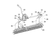
- the leveling device 20 is attached to the planting frame 15 that supports the planting unit 4 via the support link mechanism 30.
- the support link mechanism 30 supports the leveling device 20 so as to be movable up and down (turned) with respect to the planting unit 4. That is, the leveling device 20 can change the height with respect to the planting part 4 according to the raising and lowering of the support link mechanism 30.
- the support link mechanism 30 includes a rotating shaft 31 provided along the extending direction of the leveling device 20 (the width direction of the planting frame 15), an arm 32 fixed to both ends of the rotating shaft 31, and the arm 32 and the leveling device 20. While connecting, it is provided with the up-and-down link 33 which supports the leveling apparatus 20, and the auxiliary arm 34 which connects the lower end of the up-and-down link 33 and the planting frame 15.
- the rotating shaft 31 is rotatably supported by the planting frame 15 via support arms 35 at both ends.
- the arm 32 rotates and the vertical link 33 moves up and down as the rotary shaft 31 rotates, so that the planting frame 15 (planting unit 4) of the leveling device 20.
- the height relative to can be changed.
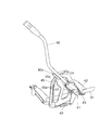
- an operation lever 40 is provided at the center of the rotation shaft 31 to rotate the rotation shaft 31 (operate the support link mechanism 30 up and down).
- the rotation base 41 of the operation lever 40 is supported to be rotatable with respect to the rotation shaft 31.
- the rotation base 41 is provided so as to protrude in the radial direction from the rotation shaft 31.
- the rotation base 41 is urged downward by a contact bracket 42 fixed to the rotation shaft 31.
- the contact bracket 42 contacts the rotation base 41 from above.
- a torsion spring 43 is provided between the contact bracket 42 and the rotation base 41.
- the torsion spring 43 is wound around the rotary shaft 31, and one end is fixed to the rotating base 41 and the other end is fixed to the contact bracket 42.
- the contact bracket 42 and the rotation base 41 are urged toward the direction in which they contact each other by the elastic force of the torsion spring 43. That is, the operation lever 40 is connected to the rotation shaft 31 via the rotation base 41 and the contact bracket 42, and the rotation operation of the operation lever 40 is configured to be interlocked with the rotation shaft 31.
- a holding bracket 45 that holds the rotation position of the operation lever 40 is provided on the side of the operation lever 40.
- the holding bracket 45 is fixed to the planting frame 15.
- the holding bracket 45 is provided with a plurality of locking grooves 45a at predetermined heights.
- the rotation base 41 of the operation lever 40 and the lower end of the holding bracket 45 are connected by a spring 46, and the operation lever 40 is urged by the spring 46 so as to rotate upward. That is, when the engagement plate 40a is removed from the locking groove 45a, the urging force of the spring 46 acts in the direction in which the operation lever 40 rotates upward.
- the operation lever 40 is urged toward the holding bracket 45 by the return spring 47. Thereby, the engagement state of the engagement plate 40a of the operation lever 40 and the locking groove 45a of the holding bracket 45 is maintained.
- the leveling device 20 when a load directed upward is applied to the leveling device 20, for example, when passing through an inflated hard headland, the leveling device 20 tends to move upward. Then, the load is transmitted as a rotational force to the rotary shaft 31 via the vertical link 33.
- the rotational force applied to the rotary shaft 31 is larger than the elastic force of the torsion spring 43, that is, when a large load acts on the leveling device 20, the contact bracket 42 is separated from the rotation base 41 of the operation lever 40, The upward movement of the leveling device 20 can be allowed regardless of the holding position of the operation lever 40.
- the leveling device 20 is moved upward according to the elastic force of the torsion spring 43. Can be prevented from being damaged. Further, the vertical movement can be absorbed by the elastic force of the torsion spring 43. Further, even when the leveling device 20 is lowered from the float 14 while traveling on a hard road such as an asphalt road surface (a state where the planting part 4 is lowered), the leveling device 20 is in contact with the road surface. By allowing movement to the ascending side, damage can be prevented. Further, by appropriately changing the elastic coefficient of the torsion spring 43, the ground load between the leveling device 20 and the field can be changed. For this reason, the optimal ground load can be selected according to the field conditions, planting conditions, and the like.
- the apparatus configuration can be made compact.
- the vertical link 33 is provided between the rear wheel 11 and the float 14.
- a mud-proof plate 36 is provided on the lower front surface of the vertical link 33.
- the mud plate 36 is a plate-like member whose upper part is bent rearward, and prevents mud splashed by the rear wheel from being applied to the float 14 and also lands the mud splashed by the inclined shape on the ground. By dropping in front of the device 20, mud does not affect the planting operation.
- the planting unit 4 is configured to be movable up and down by the lifting unit 5 and at the same time is configured to be tiltable right and left around the center in the body width direction.
- the left and right inclination of the vehicle body traveling part corresponding to the inclination of the farm field is detected by the inclination sensor 53, and the right and left inclination of the planting part 4 is adjusted using the detection result and the like.
- the horizontal control which makes the planting part 4 follow the inclination of an agricultural field and incline, and the planting part 4 becomes horizontal with respect to a rice field is performed.
- the engine speed is controlled to be lower than the idling speed, so the vibration of the airframe increases.
- a control configuration is provided that appropriately processes the detection result by the inclination sensor 53 during the seedling joining operation and appropriately maintains the inclination angle of the planting unit 4.
- the control device 50 is configured to detect the operation position of the position switch 51 that detects the operation position of the main shift lever, and the planting unit inclination setting dial that sets the inclination angle of the planting unit 4 with respect to the horizontal plane.
- the switch 52 is connected to an inclination sensor 53 that detects the horizontal inclination of the traveling unit and an inclination sensor 54 that detects the horizontal inclination of the planting unit 4.
- the setting value 52 is input from the setting switch 52
- the detection value B is input from the inclination sensor 53
- the detection value C is input from the inclination sensor 54 to the control device 50.
- the inclination angle of the planting unit 4 is determined according to the set value A, the detected value B, and the detected value C, and an output value D is output.
- the setting value A is acquired from the setting switch 52
- the detection value B is acquired from the inclination sensor 53
- the detection value C is acquired from the inclination sensor 54.
- the output value D is determined after fixing the value of the detection value B as the median value. That is, by inputting the detection value B relating to the left / right inclination of the traveling unit as a median value as a stationary state, the fluctuation of the detection value B of the inclination sensor 53 caused by engine vibration is invalidated, and the right / left inclination of the planting unit 4 The angle change is not affected.
- the tilt sensor 53 may erroneously detect the vibration of the engine as a left / right tilt, or the tilt sensor 53 may unexpectedly detect the tilt of the traveling unit due to the operator moving on the machine body.
- the setting angle of the planting part 4 can be maintained so as to be horizontal with respect to the rice field, and the seedling joining operation can be performed smoothly.
- a low-pass filter 55 that filters the detection value B from the inclination sensor 53 may be provided.
- the low-pass filter 55 has a cutoff frequency set as an engine vibration frequency during low-speed rotation during seedling work, and removes high-frequency components resulting from engine vibration.
- the detection value B1 after passing through the low-pass filter 55 eliminates the pulsation and avoids malfunction of the tilt sensor 53 due to engine vibration.
- the inclination angle can be controlled to be appropriate for the inclination.
- the control device 50 neutralizes the shift stage of the transmission of the transmission 6, disengages the main clutch, braking It is also possible to perform at least one of the operations of the device. Thereby, the front and rear wheels can be stopped, and the seedling operation can be performed more smoothly.
- the position detection switch 51 detects the seedling joining position, the horizontal control of the planting unit 4 can be stopped.
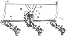
- the planting transmission case 8 for transmitting the power from the PTO shaft 7 to the planting unit 4 is an upper portion provided along the body width direction (left-right direction) in the planting frame 15. It is disposed between the guide rail 61 and the lower guide rail 62 and is detachably attached to the upper guide rail 61 via a stay 63.
- the stay 63 is formed in a shape in which the attachment side to the upper guide rail 61 is branched into a plurality (two in this embodiment). That is, the mounting position of the upper part of the stay 63 and the upper guide rail 61 is configured to be two or more.
- the planting transmission case 8 can be stably supported by the upper guide rail 61, and the planting transmission case 8 to which a large load is applied when power enters and exits can be stably and firmly fixed.
- a configuration may be provided in which a fixing portion for the extended portion related to the stay 63 is provided.
- the lower portion of the planting transmission case 8 is fixed to the lower guide rail 62 via a bracket 64.
- the front portion of the planting transmission case 8 is detachably supported by a rolling fulcrum shaft 66 that supports the planting unit 4 so as to be tiltable left and right via the receiving cylinder 65.
- the planting transmission case 8 that has weight and is subjected to a large load due to power input and output is provided with two or more points on the upper guide rail 61 via the stay 63, the lower guide rail 62, and the rolling fulcrum shaft 66. And can be supported at least at four or more points, and can be more stably and firmly fixed.
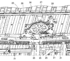
- the planting streak clutch is composed of a unit clutch that is connected to the rotation shaft of each planting claw and operates on / off of power transmission, and each unit clutch has a wire 21 respectively.
- the motor unit 22 To the motor unit 22.
- the rotary shaft of each rotary case where each planting claw is arranged is linked to the planting claw drive shaft via each unit clutch, and each unit clutch transmits power from the planting claw drive shaft to the rotary shaft. Is turned on and off.
- the planting streak clutch is configured such that each unit clutch is operated through the sliding of the wire 21 by driving the motor of the motor unit 22, and the motor unit 22 is an upper horizontal frame in a substantially central upper part of the front surface of the seedling stage 12. It is attached to 13 by bolting or the like via a bracket.
- the planting line stopping clutch is used when the rice transplanter 1 plantes seedlings at the end of the field, etc.
- the motor unit 22 pushes and pulls the wires 21 connected to the unit clutches to perform the stapling.
- the cam 26 of the motor unit 22 is controlled and driven by an electric motor device 28 attached to a stay member 29 with bolts.
- the unit clutch is operated by pushing and pulling the wire 21 with a lift by a cam 26 via a link member 25.
- the cam 26 is provided with a gear 27.
- the cam 26 and the gear 27 are integrally fixed with a bolt and rotate around a central rotation shaft.
- the central rotation shaft is fixed to the seedling stage 12 via a stay member 29 or the like.
- connection length of the wires 21 connecting the motor unit 22 and each unit clutch is configured so that the lengths of the respective wires 21 are substantially equal. Therefore, it is not necessary to provide any length of connection of the wire 21 so that the wire 21 can be prevented from being twisted or damaged, and maintainability can be improved. can do.
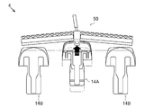
- the leveling device 50 shown in FIG. 14 is arranged so that the center is disposed forward, and is inclined from the front toward the rear as it goes from the center to both sides. That is, it is provided so that the central portion is positioned in front of other portions.
- the leveling device 50 is arranged in a square shape.
- a leveling transmission case 74 is disposed in the center of the leveling device 50, and power is transmitted from the center to both sides.
- the square-shaped leveling apparatus 50 is a front part of the planting part 4, Comprising: It is provided ahead of the float 14 which consists of center float 14A and the side float 14B.
- a part of the power from the drive shaft 9 is branched to the leveling transmission shaft 71 via the rear axle case 10, and is directed from the leveling transmission shaft 71 to both sides via the universal joint 72, the input shaft 73 and the leveling transmission case 74. Then, it is transmitted to the drive shaft 75 extended.
- a plurality of rotors 76 are fixed to each drive shaft 75, and the rotor 76 is rotated by the rotational drive of the drive shaft 75, and the field is leveled.
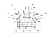
- the input shaft 43, the idler shaft 80, and the drive shaft 75 are disposed in the leveling transmission case 74.
- a bevel gear 51 is fixed to the end of the input shaft 73.
- the bevel gear 81 meshes with a bevel gear 82 fixed to the middle part of the idler shaft 80.
- Tapered gears 83 are disposed at both ends of the idler shaft 80.
- the taper gear 83 meshes with a spur gear 84 provided at the end of the drive shaft 75.
- the leveling transmission case 74 is disposed at the center, and the drive shafts 75 on both the left and right sides are inclined rearward with respect to the case.
- the drive shaft 75 is disposed laterally around the input shaft 73, and the idler shaft 80 is disposed between the input shaft 73 and the drive shaft 75, whereby the drive shaft 75 is disposed on both sides.
- the direction of rotation is the same.
- the idler shaft 80 is disposed behind the input shaft 73, and the idler shaft 80 meshes with the drive shaft 75 from the rear side.
- the position of the input shaft 73 can be moved backward.
- the leveling transmission case 74 can be comprised compactly, and between irregular regions can be made small. That is, as shown in FIG. 15, in the leveling transmission case 74, the intersection Q of the central axes of the drive shafts 75 arranged on the left and right is located in the middle of the input shaft 73.
- the bevel gear 81 of the input shaft 73 and the bevel gear 82 of the idler shaft 80 mesh with each other behind the intersection point Q, and the size of the leveling transmission case 74 in the front-rear direction can be made compact.
- the idler shaft 80 is disposed offset behind the input shaft 73 and the drive shafts 75 and 75, thereby preventing the width of the leveling transmission case 74 from increasing in the left-right direction.
- the leveling transmission case 74 is configured to reduce the width in the left-right direction while reducing the width in the front-rear direction.
- the leveling device 50 in a square shape, the flow of water generated by the rotor 76 can be directed inward, and the mud flow toward the side of the rice transplanter 1 (adjacent seedlings) Flow out can be suppressed. Thereby, when passing the side of the adjacent seedling which has already been planted, it is possible to suppress the problem of being overturned by the mud flow.
- the leveling device 50 in an inclined shape, it is possible to provide an inclination in the traveling direction and the rotation direction of the leveling device 50, and it is possible to suppress the biting of foreign matters into the rotor 76.
- the leveling work is performed in a state where the adjacent rotors 76 partially overlap, so that it is possible to reduce between irregular areas, It can be leveled more cleanly.
- a space can be secured in front of the center float 14 ⁇ / b> A by arranging the leveling device 50 in a U-shape when viewed from above. As shown in FIG. 16, the center float 14 ⁇ / b> A can be moved and arranged toward the center of the leveling device 50 using this space. By arranging the center float 14A in the front, the sensing accuracy by the float can be improved. Alternatively, it is possible to extend the center float 14A forward by using the space formed by the leveling device 50, and in this case as well, the sensing accuracy can be improved by the float.
- the power input position to the leveling device 50 does not need to be strictly in the center.
- the input shaft is positioned at a position where the leveling transmission shaft 71 is straight toward the rear and the folding angle of the universal joint 72 is the smallest.
- 73 may be arranged. In this case, it may be slightly shifted to the left or right from the center in the width direction.
- the present invention can be used for a rice transplanter equipped with a leveling device for headland leveling.
Landscapes
- Life Sciences & Earth Sciences (AREA)
- Soil Sciences (AREA)
- Environmental Sciences (AREA)
- Engineering & Computer Science (AREA)
- Mechanical Engineering (AREA)
- Zoology (AREA)
- Transplanting Machines (AREA)
- Soil Working Implements (AREA)
Abstract
Description
田植機の作業走行中に整地装置に石や異物が衝突し、整地装置の整地ロータに対して前後方向から外力が与えられた場合であっても、補強ステーの支持により、当該整地ロータがたわむことにより破損することを防止している。
植付部4における植え付け位置前方には複数のフロート14が配置される。植付部4において、フロート14の前方に整地装置20が配置されている。
図2に示すように、整地装置20は、支持リンク機構30を介して、植付部4を支持する植付フレーム15に取り付けられる。支持リンク機構30は、整地装置20を植付部4に対して昇降(回動)可能に支持する。つまり、整地装置20は、支持リンク機構30の昇降に応じて植付部4に対する高さを変更可能である。
回転軸31は、両端部において支持アーム35を介して植付フレーム15に回動自在に支持される。このように、支持リンク機構30では、回転軸31の回動に伴って、アーム32が回動して上下リンク33が上下動することで整地装置20の植付フレーム15(植付部4)に対する高さを変更可能である。
回動基部41は、回転軸31に固定される当接ブラケット42によって下方に向けて付勢されている。当接ブラケット42は、回動基部41に対して上方から当接する。当接ブラケット42と回動基部41の間にはねじりバネ43が設けられる。ねじりバネ43は、回転軸31に巻きつけられ、一端が回動基部41、他端が当接ブラケット42にそれぞれ固定される。ねじりバネ43の弾性力によって当接ブラケット42と回動基部41とが互いに当接する方向に向けて付勢されている。つまり、操作レバー40は回動基部41及び当接ブラケット42を介して回転軸31と連結され、操作レバー40の回動操作が回転軸31に連動するように構成されている。
操作レバー40の回動基部41と保持ブラケット45の下端とはバネ46によって連結されており、バネ46によって操作レバー40が上方に向けて回動するように付勢される。つまり、係合板40aを係止溝45aから外すと、バネ46の付勢力は、操作レバー40が上方に向けて回動する方向に作用する。
回転軸31に加わる回転力がねじりバネ43の弾性力よりも大きい場合、つまり大きな荷重が整地装置20に作用する場合は、当接ブラケット42が操作レバー40の回動基部41から離れることによって、操作レバー40の保持位置に依らずに整地装置20の上方への移動を許容できる。
また、アスファルト路面等の硬い路上を走行中に整地装置20をフロート14よりも下げた状態(植付部4を最下降させた状態)で、整地装置20が路面と接触しても整地装置20の上昇側への移動を許容することで、その破損を防止できる。
また、ねじりバネ43の弾性係数を適宜変更することによって、整地装置20と圃場との接地荷重を変更できる。このため、圃場条件、植付条件等に応じて最適の接地荷重を選択可能である。
植付部4は、昇降部5によって昇降可能に構成されると同時に、機体幅方向の中央を中心として左右傾斜も可能に構成されている。通常作業時は、圃場の傾斜に応じた機体走行部の左右傾斜を傾斜センサ53で検知し、その検知結果等を用いて植付部4の左右方向の傾斜を調整する。これにより、植付部4を圃場の傾斜に追従させて傾斜させて、植付部4が田面に対して水平になるようにする水平制御が実行されている。
苗継ぎ作業時には、エンジン回転数がアイドル回転数よりも低くなるように制御されるため、機体の振動が大きくなる。これにより、傾斜センサ53が誤検知することで、植付部4の傾斜角度が適切に保たれないという不具合が発生し得ることが知られている。そこで、本実施形態では、苗継ぎ作業時の傾斜センサ53による検知結果を適切に処理して、植付部4の傾斜角度を適切に保持する制御構成を提供する。
制御装置50において、設定値A、検出値B及び検出値Cに応じて植付部4の傾斜角度を決定し、出力値Dを出力する。
これにより、苗継ぎ作業時に、エンジンの振動を傾斜センサ53が左右傾斜として誤検知したり、作業者が機体上を移動する等して傾斜センサ53が不意に走行部の傾斜を検知したりしても、植付部4の設定角度を田面に対して水平になるように維持して、苗継ぎ作業をスムーズに行うことができる。
この場合、図9に示すように、ローパスフィルタ55を通過した後の検出値B1では脈動が除去されてエンジン振動に起因する傾斜センサ53の誤作動を回避できる。特に、傾斜センサ53による検知結果を無効とせずに、例えば走行部が緩やかに傾いた場合には、その傾斜に対して適切な傾斜角度に制御することができる。
なお、位置検出スイッチ51によって苗継ぎ位置を検知した場合に、植付部4の水平制御を停止させるように構成することも可能である。
図10及び図11に示すように、PTO軸7からの動力を植付部4へ伝達する植付伝動ケース8は、植付フレーム15において、機体幅方向(左右方向)に沿って設けられる上部ガイドレール61と下部ガイドレール62の間に配置されるとともに、上部ガイドレール61に対してステー63を介して着脱自在に取り付けられる。
ステー63は、上部ガイドレール61への取り付け側が複数(本実施形態では二つ)に分岐する形状に形成される。つまり、ステー63の上部と上部ガイドレール61との取付位置が二箇所以上となるように構成されている。これにより、植付伝動ケース8を上部ガイドレール61によって安定的に支持することができ、動力の出入りにより大きな負荷がかかる植付伝動ケース8を安定かつ強固に固定することができる。
なお、田植機1の条数に応じて上部ガイドレール61を左右方向に延長する場合は、ステー63に係る延長部分に対する固定部を設ける構成としても良い。
このような構成により、重量を有し、動力の出入りにより大きな負荷がかかる植付伝動ケース8を、ステー63を介して上部ガイドレール61に二点以上と、下部ガイドレール62及びローリング支点軸66とで、併せて少なくとも四点以上で支持することができ、より安定的かつ強固に固定することができる。
図12及び図13に示すように、植付条止めクラッチは、各植付爪の回転軸に連結され、動力伝達の入切を操作するユニットクラッチよりなり、各ユニットクラッチは、それぞれワイヤー21を介してモーターユニット22に接続される。各植付爪が配置される各ロータリーケースの回転軸は、各ユニットクラッチを介して植付爪駆動軸に連動連結されており、各ユニットクラッチにより植付爪駆動軸から回転軸への動力伝達が入切される。
植付条止めクラッチは、例えば図13に示す6条植えの田植機1の植付部4において、各2条毎にユニットクラッチを入り切りして田植機1が圃場の端などで苗を植え付ける際に不要な植え付けを防ぐためのものであり、前記モーターユニット22によって各ユニットクラッチに連結したワイヤー21を押し引き操作して条止めを行うように構成されている。
図14に示す整地装置50は、中央が前方に配置され、中央から両側方に向かうに従ってそれぞれ前方から後方に向けて傾斜するように配置される。つまり、中央部が他の部位よりも前方に位置するように設けられている。上面視では、整地装置50はハの字状に配置される。整地装置50の中央には整地伝動ケース74が配置され、中央から両側方に動力が伝達される。そして、ハの字状の整地装置50は、植付部4の前部であって、センターフロート14Aとサイドフロート14Bからなるフロート14の前方に設けられている。駆動軸9からの動力の一部がリアアクスルケース10を介して整地伝動軸71に分岐され、整地伝動軸71からユニバーサルジョイント72、入力軸73及び整地伝動ケース74を介して、両側方に向けて延出される駆動軸75に伝達される。各駆動軸75には、複数のロータ76が固定され、駆動軸75の回転駆動によってロータ76が回転して圃場が整地される。
このように、整地装置50の駆動系においては、整地伝動ケース74を中央に配置して、それを基点に左右両側方の駆動軸75を後方に傾斜させている。そこで、整地伝動ケース74では、入力軸73を中心として側方に駆動軸75が配置され、入力軸73と駆動軸75の間にアイドラ軸80を配置することによって、両側方に駆動軸75の回転方向を同一方向にしている。
このように、アイドラ軸80を配置することにより、入力軸73の位置を後方に寄せることができる。これにより、整地伝動ケース74をコンパクトに構成でき、不整地区間を小さくできる。
すなわち、図15に示すように、整地伝動ケース74内において、左右に配置される駆動軸75の中心軸の交点Qが入力軸73の中途部に位置する。このため、交点Qよりも後ろ側で入力軸73の傘歯車81とアイドラ軸80の傘歯車82とが噛み合うこととなり、整地伝動ケース74の前後方向の大きさをコンパクトにできる。また、アイドラ軸80を入力軸73及び駆動軸75・75の後方にオフセットさせて配置することで、整地伝動ケース74の左右方向の幅が大きくなることを防いでいる。このように、整地伝動ケース74は、前後方向の幅を小さくしつつ、左右方向の幅も小さくなるように構成されている。
また、整地装置50を傾斜状に配置することにより、進行方向と整地装置50の回転方向に傾斜を持たせることができ、夾雑物等のロータ76への噛み込みを抑制できる。さらに、田植機1の進行方向に対して傾斜した方向に整地することとなり、進行方向から見ると隣接するロータ76が一部重なった状態で整地作業が行われるため、不整地区間を少なくでき、よりきれいに均すことができる。なお、整地伝動ケース74の後方に整地用のレーキを別体として取り付けることで不整地区間が生じないようにすることも可能である。
若しくは、整地装置50によって形成されるスペースを利用して、センターフロート14Aを前方に延出することも可能であり、係る場合も同様にフロートによるセンシング精度の向上を図ることができる。
Claims (3)
- 枕地整地用の整地装置を備える田植機であって、
前記整地装置は、植付部に設けられる支持リンク機構を介して当該植付部に対して昇降可能に支持され、
前記支持リンク機構は、当該支持リンク機構を介して前記整地装置を昇降操作するための操作レバーを含み、
前記操作レバーは、当該操作レバーの操作に依らずに整地装置の上昇側への移動を許容することを特徴とする田植機。 - 前記支持リンク機構は、前記整地装置の延出方向に沿って設けられる回転軸を有し、当該回転軸の回転運動に応じて前記整地装置を昇降可能に構成され、
前記操作レバーの回動基部は、前記回転軸に回動自在に設けられ、
前記操作レバーの回動基部に、前記回転軸に固定され、前記回動基部の上方側から当接する当接ブラケットと、前記回動基部と前記当接ブラケットを互いに当接する方向に付勢する弾性部材と、が設けられる請求項1に記載の田植機。 - 前記支持リンク機構は、前記回転軸の回転運動に応じて上下方向に移動する上下リンクを備え、
前記上下リンクは、後輪の後方であって前記植付部のフロートの前方に配置されるとともに、その前面に防泥板が設けられる請求項2に記載の田植機。
Priority Applications (3)
| Application Number | Priority Date | Filing Date | Title |
|---|---|---|---|
| CN201280077116.4A CN104812233B (zh) | 2012-11-21 | 2012-11-21 | 插秧机 |
| KR1020157015602A KR101967504B1 (ko) | 2012-11-21 | 2012-11-21 | 이앙기 |
| PCT/JP2012/080243 WO2014080485A1 (ja) | 2012-11-21 | 2012-11-21 | 田植機 |
Applications Claiming Priority (1)
| Application Number | Priority Date | Filing Date | Title |
|---|---|---|---|
| PCT/JP2012/080243 WO2014080485A1 (ja) | 2012-11-21 | 2012-11-21 | 田植機 |
Publications (1)
| Publication Number | Publication Date |
|---|---|
| WO2014080485A1 true WO2014080485A1 (ja) | 2014-05-30 |
Family
ID=50775690
Family Applications (1)
| Application Number | Title | Priority Date | Filing Date |
|---|---|---|---|
| PCT/JP2012/080243 Ceased WO2014080485A1 (ja) | 2012-11-21 | 2012-11-21 | 田植機 |
Country Status (3)
| Country | Link |
|---|---|
| KR (1) | KR101967504B1 (ja) |
| CN (1) | CN104812233B (ja) |
| WO (1) | WO2014080485A1 (ja) |
Families Citing this family (4)
| Publication number | Priority date | Publication date | Assignee | Title |
|---|---|---|---|---|
| CN105766166A (zh) * | 2016-04-16 | 2016-07-20 | 潍坊同方机械有限公司 | 四驱插秧机 |
| IT201600091430A1 (it) * | 2016-09-09 | 2018-03-09 | Prinoth Spa | Veicolo battipista |
| CN108307746B (zh) * | 2018-04-09 | 2023-09-29 | 安徽农业大学 | 一种无人驾驶插秧机栽插离合手柄自动换档装置及其控制方法 |
| CN109348798B (zh) * | 2018-12-18 | 2023-09-22 | 重庆科技学院 | 一种多用途地面实时自动仿形装置 |
Citations (3)
| Publication number | Priority date | Publication date | Assignee | Title |
|---|---|---|---|---|
| JPH0166803U (ja) * | 1987-10-23 | 1989-04-28 | ||
| JP2000270629A (ja) * | 1999-03-25 | 2000-10-03 | Kubota Corp | 水田作業機 |
| JP2005095017A (ja) * | 2003-09-22 | 2005-04-14 | Mitsubishi Agricult Mach Co Ltd | 移植機 |
Family Cites Families (2)
| Publication number | Priority date | Publication date | Assignee | Title |
|---|---|---|---|---|
| JP4389122B2 (ja) * | 2006-02-27 | 2009-12-24 | 井関農機株式会社 | 苗移植機 |
| JP2008228598A (ja) | 2007-03-17 | 2008-10-02 | Yanmar Co Ltd | 田植機 |
-
2012
- 2012-11-21 KR KR1020157015602A patent/KR101967504B1/ko active Active
- 2012-11-21 WO PCT/JP2012/080243 patent/WO2014080485A1/ja not_active Ceased
- 2012-11-21 CN CN201280077116.4A patent/CN104812233B/zh active Active
Patent Citations (3)
| Publication number | Priority date | Publication date | Assignee | Title |
|---|---|---|---|---|
| JPH0166803U (ja) * | 1987-10-23 | 1989-04-28 | ||
| JP2000270629A (ja) * | 1999-03-25 | 2000-10-03 | Kubota Corp | 水田作業機 |
| JP2005095017A (ja) * | 2003-09-22 | 2005-04-14 | Mitsubishi Agricult Mach Co Ltd | 移植機 |
Also Published As
| Publication number | Publication date |
|---|---|
| KR20150085006A (ko) | 2015-07-22 |
| KR101967504B1 (ko) | 2019-04-09 |
| CN104812233B (zh) | 2017-06-30 |
| CN104812233A (zh) | 2015-07-29 |
Similar Documents
| Publication | Publication Date | Title |
|---|---|---|
| JP5772222B2 (ja) | 作業車両 | |
| JP2012244939A5 (ja) | ||
| CN104812233B (zh) | 插秧机 | |
| JP5418537B2 (ja) | 乗用田植機 | |
| JP2007252319A (ja) | 農作業機 | |
| JP5391668B2 (ja) | 苗植機 | |
| JP2007252319A5 (ja) | ||
| JP5867558B2 (ja) | 乗用田植機 | |
| JP4484754B2 (ja) | 田植機 | |
| JP4893701B2 (ja) | 乗用田植機 | |
| JP5736842B2 (ja) | クラッチ | |
| JP2010213638A (ja) | 田植機 | |
| JP2010124730A5 (ja) | ||
| JP4241738B2 (ja) | 農作業機 | |
| JP2007174932A (ja) | 対地作業装置付き苗移植機 | |
| JP2013066391A5 (ja) | ||
| JP2012180875A5 (ja) | ||
| JP5027908B2 (ja) | 作業車の作業装置昇降構造 | |
| JP3717430B2 (ja) | 乗用型作業車 | |
| CN102355810B (zh) | 乘用型农用作业机及作为其一例的乘用型插秧机 | |
| JP3591132B2 (ja) | 表土耕起付き乗用型田植機 | |
| JP2007261579A (ja) | 水田作業機 | |
| JP2010000837A (ja) | 作業機の操向角検出構造 | |
| JP4382677B2 (ja) | 作業車 | |
| JP5888291B2 (ja) | 乗用田植機 |
Legal Events
| Date | Code | Title | Description |
|---|---|---|---|
| 121 | Ep: the epo has been informed by wipo that ep was designated in this application |
Ref document number: 12888965 Country of ref document: EP Kind code of ref document: A1 |
|
| NENP | Non-entry into the national phase |
Ref country code: DE |
|
| ENP | Entry into the national phase |
Ref document number: 20157015602 Country of ref document: KR Kind code of ref document: A |
|
| 122 | Ep: pct application non-entry in european phase |
Ref document number: 12888965 Country of ref document: EP Kind code of ref document: A1 |
|
| NENP | Non-entry into the national phase |
Ref country code: JP |