WO2014077241A1 - 吸収性物品 - Google Patents
吸収性物品 Download PDFInfo
- Publication number
- WO2014077241A1 WO2014077241A1 PCT/JP2013/080532 JP2013080532W WO2014077241A1 WO 2014077241 A1 WO2014077241 A1 WO 2014077241A1 JP 2013080532 W JP2013080532 W JP 2013080532W WO 2014077241 A1 WO2014077241 A1 WO 2014077241A1
- Authority
- WO
- WIPO (PCT)
- Prior art keywords
- low
- sheet
- pressure
- absorbent article
- annular
- Prior art date
- Legal status (The legal status is an assumption and is not a legal conclusion. Google has not performed a legal analysis and makes no representation as to the accuracy of the status listed.)
- Ceased
Links
Images




Classifications
-
- A—HUMAN NECESSITIES
- A61—MEDICAL OR VETERINARY SCIENCE; HYGIENE
- A61F—FILTERS IMPLANTABLE INTO BLOOD VESSELS; PROSTHESES; DEVICES PROVIDING PATENCY TO, OR PREVENTING COLLAPSING OF, TUBULAR STRUCTURES OF THE BODY, e.g. STENTS; ORTHOPAEDIC, NURSING OR CONTRACEPTIVE DEVICES; FOMENTATION; TREATMENT OR PROTECTION OF EYES OR EARS; BANDAGES, DRESSINGS OR ABSORBENT PADS; FIRST-AID KITS
- A61F13/00—Bandages or dressings; Absorbent pads
- A61F13/15—Absorbent pads, e.g. sanitary towels, swabs or tampons for external or internal application to the body; Supporting or fastening means therefor; Tampon applicators
- A61F13/53—Absorbent pads, e.g. sanitary towels, swabs or tampons for external or internal application to the body; Supporting or fastening means therefor; Tampon applicators characterised by the absorbing medium
- A61F13/531—Absorbent pads, e.g. sanitary towels, swabs or tampons for external or internal application to the body; Supporting or fastening means therefor; Tampon applicators characterised by the absorbing medium having a homogeneous composition through the thickness of the pad
- A61F13/532—Absorbent pads, e.g. sanitary towels, swabs or tampons for external or internal application to the body; Supporting or fastening means therefor; Tampon applicators characterised by the absorbing medium having a homogeneous composition through the thickness of the pad inhomogeneous in the plane of the pad
- A61F13/533—Absorbent pads, e.g. sanitary towels, swabs or tampons for external or internal application to the body; Supporting or fastening means therefor; Tampon applicators characterised by the absorbing medium having a homogeneous composition through the thickness of the pad inhomogeneous in the plane of the pad having discontinuous areas of compression
-
- A—HUMAN NECESSITIES
- A61—MEDICAL OR VETERINARY SCIENCE; HYGIENE
- A61F—FILTERS IMPLANTABLE INTO BLOOD VESSELS; PROSTHESES; DEVICES PROVIDING PATENCY TO, OR PREVENTING COLLAPSING OF, TUBULAR STRUCTURES OF THE BODY, e.g. STENTS; ORTHOPAEDIC, NURSING OR CONTRACEPTIVE DEVICES; FOMENTATION; TREATMENT OR PROTECTION OF EYES OR EARS; BANDAGES, DRESSINGS OR ABSORBENT PADS; FIRST-AID KITS
- A61F13/00—Bandages or dressings; Absorbent pads
- A61F13/15—Absorbent pads, e.g. sanitary towels, swabs or tampons for external or internal application to the body; Supporting or fastening means therefor; Tampon applicators
- A61F13/45—Absorbent pads, e.g. sanitary towels, swabs or tampons for external or internal application to the body; Supporting or fastening means therefor; Tampon applicators characterised by the shape
- A61F13/47—Sanitary towels, incontinence pads or napkins
- A61F13/475—Sanitary towels, incontinence pads or napkins characterised by edge leakage prevention means
- A61F13/4751—Sanitary towels, incontinence pads or napkins characterised by edge leakage prevention means the means preventing fluid flow in a transversal direction
- A61F13/4756—Sanitary towels, incontinence pads or napkins characterised by edge leakage prevention means the means preventing fluid flow in a transversal direction the means consisting of grooves, e.g. channels, depressions or embossments, resulting in a heterogeneous surface level
Definitions
- the present invention relates to an absorbent article, and more particularly, to an absorbent article such as a light incontinence pad, panty liner, sanitary napkin, cage absorbent pad, urine absorbent pad, and disposable diaper.
- an absorbent article such as a light incontinence pad, panty liner, sanitary napkin, cage absorbent pad, urine absorbent pad, and disposable diaper.
- an absorptive article provided with a surface sheet located in a wearer's skin facing side, a back sheet located in a wearer's non-skin facing side, and an absorber interposed between a top sheet and a back sheet It is known.
- Patent Document 1 a leak-proof groove formed on both left and right side portions on the skin contact surface side and extending in the longitudinal direction, and a linear crimp formed by pressure-bonding a top sheet and an absorbent body between the leak-proof grooves.
- a sanitary napkin having a recess is disclosed.
- An object of the present invention is to provide an absorbent article in which the generation of twisting and relatively large irregularities that reduce the absorption performance is suppressed without giving the wearer an unpleasant sensation.
- the present invention has a longitudinal sheet, a lateral direction, and a thickness direction orthogonal to each other, and a surface sheet positioned on the wearer's skin facing surface side, and the wearer's non-skin facing surface
- An absorptive article provided with a back sheet located in the side and an absorber interposed between the top sheet and the back sheet is assumed.
- the present invention is a vertically long shape formed by squeezing the topsheet and the absorber in a direction from the topsheet to the backsheet at a portion where the topsheet and the absorber overlap.
- the top sheet and the absorber in the direction from the top sheet to the back sheet.
- the absorption at the bottom of the low-pressure squeeze comprises a low-pressure squeeze region having a plurality of low-pressure squeeze portions formed by squeezing and an absorption central region located between the low-pressure squeeze regions formed at both ends.
- the dimension in the thickness direction of the absorbent article is larger than the dimension in the thickness direction of the absorbent article at the bottom of the annular compressed groove.
- the absorbent article Means the dimension from the top surface of the top sheet to the bottom surface of the back sheet when the dimensions are measured with the top sheet side facing up.
- the dimension in the thickness direction means “the dimension in the thickness direction of the absorbent article”.
- the depths of the plurality of low-pressure recessed portions formed at both ends in the longitudinal direction in the region surrounded by the annular compressed groove are relatively small, so that the unevenness generated in the topsheet is reduced. It is difficult for the user to feel uncomfortable. Furthermore, since the depth of the low pressing portion is relatively small, an increase in the hardness of the low pressing portion where the low pressing portion is formed is suppressed. Therefore, the deformation of the absorbent article adapted to the user's movement is not hindered. Accordingly, an absorbent article in which twisting and relatively large unevenness are suppressed without giving the user an unpleasant sensation is provided.
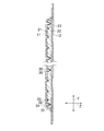
- FIG. 3 is a sectional view taken along line III-III in FIG. 1.
- Explanatory drawing which shows the embossing / debossing process for manufacturing an absorbent article.
- FIG. 5 is an enlarged sectional view taken along line VV in FIG. 4.
- FIG. 7 is a sectional view taken along line VII-VII in FIG. 6. Photograph of sample for thickness direction dimension evaluation. Measurement example of thickness direction dimension.
- a sanitary napkin 10 As shown in FIG. 1, a sanitary napkin 10 according to the present invention includes a top sheet 11 positioned on the skin facing surface side of the user, a back sheet 12 positioned on the non-skin facing surface side, the top sheet 11 and the back surface. And an absorbent body 20 interposed between the sheets 12.
- the sanitary napkin 10 has a vertically long shape in the vertical direction Y, and is substantially symmetric with respect to the vertical center line and the horizontal center line.
- the sanitary napkin 10 according to the present embodiment further includes a pair of wing portions 15 extending in a convex shape toward the laterally outer side at the longitudinal center portion of the side edge.
- the top sheet 11 and the back sheet 12 have the same shape and the same size. Both the dimensions in the lateral direction X and the longitudinal direction Y are larger than those of the absorbent body 20 and have a peripheral edge 13 extending around the absorbent body 20. .
- the top sheet 11 and the back sheet 12 are joined to each other at a peripheral edge portion 13 by a known means such as a hot melt adhesive (not shown) or heat welding. In FIG. 1, it has the joining part 18 shown with the oblique line.
- the top sheet 11 has liquid permeability and is formed of a material containing a thermoplastic synthetic resin.
- a fiber nonwoven fabric such as an air-through fiber nonwoven fabric, a point bond nonwoven fabric, or a spun bond nonwoven fabric can be suitably used.
- the thermoplastic synthetic resin include, but are not limited to, olefin polymers such as ethylene and propylene, or polyethylene terephthalate.
- the top sheet 11 preferably has a mass of about 10 to 50 g / m 2 and a thickness of about 0.5 to 2.0 mm.
- the back sheet 12 is formed of a material containing a thermoplastic resin that is hardly liquid-permeable or liquid-impervious, and for example, a plastic film or a laminate of a plastic film and a fiber nonwoven fabric can be suitably used.
- the fiber nonwoven fabric include, but are not limited to, a spunbond / meltblown / spunbond (SMS) fiber nonwoven fabric, an air-through fiber nonwoven fabric, a point bond fiber nonwoven fabric, and a spunbond fiber nonwoven fabric.
- SMS spunbond / meltblown / spunbond
- the above-mentioned synthetic resin can be used for the thermoplastic synthetic resin.
- the back sheet 12 preferably has a mass of about 10 to 50 g / m 2 and a thickness of about 0.1 to 1.0 mm.
- the top sheet 11 and the back sheet 12 it is preferable to use a material containing the same kind of resin from the viewpoint of bondability.
- the wing part 15 of the present embodiment is formed in series with the top sheet 11 and the back sheet 12.
- the wing portion 15 can be provided separately from the top sheet 11 and the back sheet 12.
- the wing part 15 is formed from the same or different kind of sheet material as the top sheet 11 or the back sheet 12, and known means such as hot melt adhesive or heat welding are formed on both side edges of the absorbent body 20 in the longitudinal direction. Can be joined.
- the absorber 20 is substantially rectangular and is interposed between the first sheet 21 located on the top sheet 11 side, the second sheet 22 located on the back sheet 12 side, and the first sheet 21 and the second sheet 22.
- a body fluid-absorbing core material 23 is provided and is formed to have a substantially uniform thickness.
- the first sheet 21 and the second sheet 22 have substantially the same shape and size, and their peripheral portions are joined to each other by a known means such as hot melt adhesive or heat welding.
- seat 21 can be formed using the liquid-permeable fiber nonwoven fabric, tissue paper, and airlaid sheet
- fiber nonwoven fabrics such as air through, a spun bond, and SMS, can be used.
- seat 21 of this embodiment is formed from an air through fiber nonwoven fabric.
- the air-through fiber nonwoven fabric is preferable because it can be relatively easily manufactured in order to reduce liquid return to the skin.
- the mass of the first sheet 21 is preferably about 10 to 60 g / m 2 , for example.
- the first sheet is preferably used from the viewpoint of retaining the shape of the core material 23 and preventing liquid return, but is not essential to the present invention. When the first sheet is not used, the core material 23 is directly covered with the top sheet 21.
- the second sheet 22 either a liquid-permeable sheet or a liquid-impermeable sheet may be used, and as the sheet, any one of a fiber nonwoven fabric, a tissue paper, and an airlaid sheet can be adopted.
- a fiber nonwoven fabric any of fiber nonwoven fabrics such as air-through, spunbond, and SMS may be used.
- seat 22 of this embodiment is formed from a SMS fiber nonwoven fabric.
- the mass of the second sheet 22 is preferably about 10 to 60 g / m 2 , for example.
- the core material 23 can be formed of at least one of known absorbent polymer particles, absorbent fibers, or hygroscopic fibers.
- absorbent polymers include, but are not limited to, starch-based, acrylic acid-based, and amino acid-based polymers.
- absorbent fibers include natural pulp fibers such as wood fluff pulp, and examples of hygroscopic fibers include, but are not limited to, recycled fibers such as rayon staples, and mixtures thereof.
- the top sheet 11 has a vertically long annular squeezed groove 31 formed by semicircular lines at both ends in the longitudinal direction Y and corrugated lines at both sides in the middle in the portion where the top sheet 11 and the absorbent body 20 overlap, Absorption center located between the low-pressure squeezed region 14 and the low-pressure squeezed region 14 having a plurality of low-pressure squeezed recesses 32 arranged intermittently at both ends in the longitudinal direction Y in the region 16 surrounded by the groove 31.
- Area 17 The annular pressing groove 31 and the low-pressure pressing recess 32 are formed by pressing the top sheet 11 and the absorbent body 20 in the direction from the top sheet 11 to the back sheet 12.
- the annular pressing groove 31 and the low pressing recess 32 can be formed by embossing / debossing.
- illustration of the pressing mark formed in the core material 23 is abbreviate
- the low pressing recessed part 32 is illustrated by a small diameter circle, the shape of the low pressing recessed part 32 is not limited to a circle.
- the region 16 surrounded by the annular compressed groove 31 is located inside the outer peripheral edge of the portion where the topsheet 11 and the absorbent body 20 overlap.
- the annular squeezing groove 31 suppresses exudation of the body fluid excreted in the region 16 to the outside.
- the absorption central region 17 located between the pair of low-pressure squeezed regions 14 formed at both ends is located at the substantially central portion of the sanitary napkin 10 and is used when worn.
- the main absorption area is formed facing the vulva of the person.
- the annular compressed groove 31 is a pair of curved constricted portions 36 that are constricted in a curved line toward the inner side in the lateral direction of the sanitary napkin 10 at both boundary portions of the pair of low pressure regions 14 and the absorption central region 17.
- the low-pressure squeezed regions 14 located on both outer sides in the longitudinal direction Y of the curved constricted portion 36 are kept flat and are easily deformed in accordance with the movement of the user's body.
- the low-pressure squeezed recess 32 and the annular squeeze groove 31 are both formed by squeezing a substantially V-shaped cross section until entering the core 23, and the thickness at the bottom 33 of the low-pressure squeezed recess 32.
- the dimension in the direction Z is larger than the dimension in the thickness direction Z at the bottom 34 of the annular pressing groove 31.
- the dimension in the thickness direction Z of the bottom 33 of the low pressing recess 32 is 50% or more of the dimension in the thickness direction Z around the low pressing recess 32, and preferably 60% or more.
- the dimension in the thickness direction Z of the bottom 34 of the annular pressing groove 31 is less than 50% of the dimension in the thickness direction Z around the annular pressing groove 31, and there is no particular lower limit value.
- the dimension in the thickness direction Z can be reduced as long as processing is possible.
- the dimension in the thickness direction Z of the sanitary napkin 10 in which the low-pressure squeezed recess 32 and the annular squeeze groove 31 are formed is substantially uniform,
- the dimension is about 2/3 of the dimension in the thickness direction Z around the low-pressure recessed portion 32, and the dimension in the thickness direction Z of the bottom 34 of the annular compressed groove 31 is the thickness around the annular compressed groove 31. It is preferably about 1/3 of the dimension in the length direction Z.
- seat 21 and the surface sheet 11 are integrated by pressing.
- the first sheet 21 and the top sheet 11 are also continuous without breaking at the bottom 33 of the low pressure recessed portion 32 and the bottom 34 of the annular compressed groove 31. If the topsheet 11 is peeled off from the first sheet 21 during use of the sanitary napkin 10, there is a risk that the product may be twisted or the absorption performance may be lowered. In this way, the first sheet 21 and the topsheet 11 Are integrated by squeezing, and it is suppressed that the surface sheet 11 peels from the 1st sheet
- the integration of the first sheet 21 and the top sheet 11 can be performed by a known means such as heat welding during embossing / debossing.
- the compression squeezing recess 32 of the present invention has a relatively small compression depth as described above, the unevenness generated in the topsheet 11 during embossing / debossing is also relatively small, resulting in an unpleasant sensation for the user. Giving can be suppressed. Moreover, as a result of suppressing the increase in the hardness of the low pressing area 14 in which the low pressing recessed part 32 is arrange
- the low pressing recessed part 32 of this invention is squeezed and formed until it reaches the inside of the core material 23 of the absorber 20, the communication with the core material 23 is high, and a bodily fluid is easy to osmose
- FIG. Furthermore, in the core material 23, the density of the pulverized pulp around the low-pressure squeezed recess 32 is higher than that in the periphery, and the absorbed liquid is easily retained. As a result, the absorbability of the sanitary napkin 10 is improved. Moreover, also in the annular pressing groove 31, the density of the pulverized pulp is higher than that of the periphery, and the absorbability is improved.
- a plurality of low-pressure squeezed recesses 32 are arranged on a virtual grid line G that is inclined with respect to the vertical direction Y. More specifically, the plurality of low-pressure squeezing recesses 32 are formed between the curved constricted portion 36 and the annular squeeze groove 31 at both ends in the longitudinal direction Y in the region 16 surrounded by the annular squeeze groove 31, that is, in the low-pressure squeeze region 14.
- the low pressure recessed part 32 is also formed in the part which becomes the outer side of the horizontal direction X with respect to the most constricted part of the curved constricted part 36 which is arrange
- the high tension portion formed along the virtual lattice line G inclined with respect to the longitudinal direction Y suppresses the formation of wrinkles parallel to the longitudinal direction Y, and the first sheet 21 of the topsheet 11. Is prevented from peeling off.
- the generation of such depressions along the virtual grid line G depends on various factors such as the physical properties of the first sheet 21 and the top sheet 11, the distance between the low-pressure depressions 32, the depth of the low-pressure depressions 32, and the like. However, the above-described effects can be obtained as long as tension is applied to the first sheet 21 and the top sheet 11 between the adjacent pressed depressions 32 on the virtual lattice line G regardless of the presence or absence of such depressions. .
- MD indicates a machine direction
- CD indicates a cross direction orthogonal to the machine direction MD
- VD is an upper and lower direction orthogonal to the machine direction MD and the cross direction CD, respectively.
- MD indicates a machine direction
- CD indicates a cross direction orthogonal to the machine direction MD
- VD is an upper and lower direction orthogonal to the machine direction MD and the cross direction CD, respectively.
- the machine direction MD corresponds to the vertical direction Y
- the cross direction CD corresponds to the horizontal direction X
- VD corresponds to the thickness direction Z.
- the continuous web 50 including the top sheet 11, the back sheet 12, and the absorbent body 20 interposed between both sheets 11 and 12 is continuously run in one direction, that is, the machine direction MD. While being held between the pair of embossing / debossing rollers 40, the topsheet 11 is embossed / debossed. At this time, the continuous web 50 is caused to travel such that the portion where the topsheet 11 and the absorbent body 20 overlap faces upward.
- the absorbent body 20 includes a body fluid-absorbing core member 23 interposed between the first sheet 21 and the second sheet 22 and is formed to have a substantially uniform thickness.
- the pair of embossing / debossing rollers 40 includes a first roller 44 and a second roller 45, and the first roller 44 is positioned above the second roller 45.
- the rotation shaft 44a of the first roller 44 and the rotation shaft 45a of the second roller 45 are parallel to each other.
- the first roller 44 is a roller that contacts the top sheet 11 during embossing / debossing, and is disposed inside the annular first protrusion 46 and the annular first protrusion 46 for forming the annular compressed groove 31.
- a plurality of second protrusions 47 for forming the low pressing recess 32 extends from the peripheral surface 44z toward the outside in the diameter direction. As shown in FIG.
- the height of the first protrusion 46 from the peripheral surface 44 z is higher than that of the second protrusion 47.
- the first roller 44 is configured such that its surface temperature can be controlled by temperature control means (not shown).
- the second roller 45 is located on the back sheet 12 side. Further, the peripheral surface 45z of the second roller 45 has a constant distance from the axis of the rotation shaft 45a and is flat.
- the clearance between the first roller 44 and the second roller 45 is set so that the portion where the top sheet 11 and the absorbent body 20 are overlapped by the first protrusion 46 and the second protrusion 47 at a desired depth. Adjust so that it can be squeezed. As an example, the clearance is adjusted within a range where the gap between the first protrusion 46 and the second roller 45 is greater than 0 mm and approximately 2 mm or less, and the compression depth is set to a desired value. Further, the continuous web 50 is machined so that the portion where the topsheet 11 and the absorber 20 overlap and the position of the first protrusion 46 and the second protrusion 47 rotating in the circumferential direction of the first roller 44 are synchronized. Drive continuously in direction MD.
- the continuous web 50 is sandwiched between the first and second rollers 44 and 45 with a certain clearance, and the pattern of the first protrusion 46 and the second protrusion 47 formed on the first roller 44 is the continuous web.
- the annular pressing groove 31 and the plurality of low-pressure pressing recesses 32 can be formed in the portion where the topsheet 11 and the absorbent body 20 overlap.
- the temperature of the first roller 44 is set to a temperature at which the top sheet 11 and the first sheet 21 can be thermally welded, for example, about 80 to 100 ° C.
- the top sheet 11 and the first sheet 21 can be integrated by heat welding.
- the first protrusions 46 and the second protrusions 47 having different heights from the peripheral surface 44z of the first roller 44 are used while the clearance between the first roller 44 and the second roller 45 is constant.
- the dimension in the thickness direction Z at the bottom 33 of the low-pressure depression 32 formed by the second protrusion 47 having a relatively low height from the peripheral surface 44z of the first roller 44 is the first protrusion. It becomes larger than the dimension of the thickness direction Z in the bottom part 34 of the annular pressing groove 31 formed of the part 46. FIG. In other words, the annular pressing groove 31 is squeezed deeper than the low pressure recess 32.
- the annular pressing groove 31 is compressed at a higher compression rate than the low-pressure pressing recess 32.
- the density of the core material 23 of the part in which the annular pressing groove 31 is formed becomes higher than the density of the core material 23 of the part in which the low pressure recessed part 32 is formed.
- the density of the core material 23 is high, the diffusion rate of body fluid is improved.
- the density of the core material 23 is relatively low, although it depends on the degree, the diffusion rate of the body fluid decreases, but the volume of the body fluid that can be absorbed and held increases.
- the sanitary napkin 10 has an annular first protrusion 46 for forming the annular pressing groove 31 and a plurality of second protrusions 47 for forming the low pressure recess 32, and the first protrusion 46.
- the sanitary napkin 10 produced using the first roller 44 whose height from the peripheral surface 44z of the second protrusion 47 is approximately twice the height of the second protrusion 47 was used.
- the sanitary napkin 10 used in this evaluation has a substantially uniform thickness.
- a portion including the low pressure recessed portion 32 and the annular compressed groove 31 was cut out to prepare an evaluation sample shown in FIG.
- the surface having the low-pressure squeezing recess 32 and the annular squeezing groove 31 of the sample for evaluation is attached on a horizontal plane, and the non-contact type keyence shape measuring device KS-1100 is set using this plane as a reference plane. Using, the height of the surface of each part of the sanitary napkin 10 with respect to the reference surface was measured.
- the height of the surface of the sanitary napkin 10 relative to the reference surface is referred to as the “apparent thickness” of the sanitary napkin 10, and by comparing the apparent thickness, the dimension in the thickness direction Z of the sanitary napkin 10 is determined. evaluated.
- the value of the apparent thickness of the annular compressed groove 31 and the low-pressure recessed portion 32 was set to the minimum apparent thickness value in the portion where they were formed by pressing.
- the annular pressing groove 31 formed in the top sheet 11 of the sample for evaluation has a bottom pressing portion 31a on the bottom surface. That is, the bottom surface of the annular pressing groove 31 has irregularities, and the dimension in the thickness direction Z is the smallest in the bottom pressing portion 31a. Moreover, the low pressing recessed part 32 formed in the surface sheet 11 of the sample for evaluation is arrange
- FIG. 9 shows the result of measuring the apparent thickness in the frame line shown in FIG. 8 using the Keyence shape measuring instrument KS-1100.
- FIG. 9A is a diagram showing the distribution of the apparent thickness when the evaluation sample is viewed from above by the change in color tone
- FIG. 9B is an apparent view of the section IXb-IXb in FIG. 9A. It is a measurement result of thickness.
- the apparent thickness of the low pressure recessed portion 32 of the sanitary napkin 10 is about 1900 ⁇ m
- the apparent thickness of the annular compressed groove 31 (bottom compressed portion 31a) is about 1000 ⁇ m.
- the apparent thickness of the low pressure recessed portion 32 is larger than the apparent thickness of the bottom portion of the annular compressed groove 31. In other words, the pressing depth of the low-pressure pressing recess 32 is smaller than the pressing depth of the annular pressing groove 31.
- the dimension in the thickness direction Z at the bottom of the low-pressure squeezing recess 32 and the dimension in the thickness direction at the bottom of the annular pressing groove 31 can be evaluated.
- the apparent thickness of the sanitary napkin 10 in a portion not compressed by the first and second protrusions 46 and 47 in the embossing / debossing process is approximately 2500 to 3000 ⁇ m. Therefore, the apparent thickness of the low-pressure recessed portion 32 is 50% or more of the apparent thickness of the sanitary napkin 10, and the apparent thickness of the annular compressed groove 31 is less than 50% of the apparent thickness of the sanitary napkin 10. ing. In the example shown in FIG.
- the apparent thickness of the sanitary napkin 10 around the low-pressure squeezed recess 32 and the annular compressed groove 31 is about 2500 to 2700 ⁇ m, whereas the sanitary napkin 10 The apparent thickness at the end is about 3000 ⁇ m.
- the sheet members (the first sheet 21 and the top sheet 11) around the low-pressure squeezing recess 32 and the annular squeezing groove 31 are compressed in the low-pressure squeezing recess 32 and the annular squeezing groove 31 by pressing during embossing / debossing. It was because it was drawn.
- Second Embodiment A second embodiment of the present invention will be described with reference to FIG. Since the basic configuration of the second embodiment is the same as that of the sanitary napkin 10 of the first embodiment, only differences will be described below.
- illustration of the pressing mark formed in the core material 23 is abbreviate
- the sanitary napkin 10 is an absorption center located between the low-pressure squeezed region 14 formed at both ends in the longitudinal direction Y in the region 16 surrounded by the annular compressed groove 31 and the low-pressure squeezed region 14.
- a pair of curvilinear lateral pressing grooves 30 that are spaced apart from the annular pressing groove 31 and extend in the lateral direction are provided on the absorption central area 17 side of both boundaries with the area 17.
- the horizontal pressing groove 30 is formed by pressing the top sheet 11 and the absorbent body 20 in the direction from the top sheet 11 to the back sheet 12 until reaching the inside of the core member 23, similarly to the annular pressing groove 31. . Further, as shown in FIG.
- the dimension in the thickness direction Z at the bottom 33 of the low-pressure squeezing recess 32 is larger than the dimension in the thickness direction Z at the bottom 35 of the lateral pressing groove 30.
- the dimension of the thickness direction Z in the bottom part 35 of the horizontal pressing groove 30 can be made substantially the same as the dimension of the thickness direction Z in the bottom part 34 of the annular pressing groove 31, it is not limited to this.
- a force in the lateral direction X is applied from both legs of the user toward the inside of the sanitary napkin 10. Since the sanitary napkin 10 which concerns on 2nd Embodiment is equipped with the horizontal pressing groove
- abuts a user's vulva part is surrounded by a pair of horizontal pressing groove 30 extended in the horizontal direction X, and the both sides of the annular pressing groove 31 extended in the vertical direction Y. Even when a force in the lateral direction X is applied, deformation of the absorption central region 17 is effectively suppressed. As a result, the state where the absorption central region 17 is in contact with the user's vulva is easily maintained. Moreover, since the density of a pulverized pulp becomes high compared with the periphery also in the horizontal pressing groove 30 similarly to the annular pressing groove 31, body fluid absorbency improves.
- the low-pressure squeezing recess 32 disposed in the low-pressure squeezing region 14 is formed by integrating the first sheet 21 and the top sheet 11 by squeezing, so that friction due to the movement of the user is caused. Since the surface sheet 11 is prevented from peeling from the first sheet 21 and the unevenness generated in the surface sheet 11 is relatively small, it is difficult to cause an unpleasant sensation to the user. Furthermore, since the increase in the hardness of the low pressure area 14 is suppressed, deformation of the absorbent article adapted to the movement of the user is not hindered, and wrinkles parallel to the longitudinal direction Y are formed. As a result of suppressing the irregular deformation of the product, it is possible to improve the feeling of use and prevent leakage.
- the horizontal squeezing groove 30 provided at the boundary between the low pressure squeezing region 14 and the absorption central region 17 causes the absorption central region 17 to It is possible to prevent the deformation from propagating.
- the low-pressure squeezed recess 32 can be disposed between the pair of lateral squeezed grooves 30, that is, in the absorption central region 17.
- the absorption center area 17 is a part that abuts against the user's vulva part.
- the sanitary napkin 10 according to the present embodiment is embossed using a roller (not shown) in which a protrusion for forming the lateral pressing groove 30 is added to the first roller 44 shown in the first embodiment. / Can be manufactured by debossing.
- the present invention has been described based on the embodiment, the present invention is not limited to this and can be implemented with various modifications.
- the curved constricted portion 36 may not be provided in the annular compressed groove 31.
- the low pressing recessed part 32 is arrange
- the core member 23 can be covered with a single sheet, for example, tissue paper, or the first sheet 21. Can be omitted.
- tissue paper for example, tissue paper
- the thickness of the absorber 20 of the part corresponded to the absorption center area 17 can be enlarged, and it can also be made to contact
- the present invention is not limited to the sanitary napkin 10 and may be applied to absorbent articles such as light incontinence pads, panty liners, vaginal absorption pads, urine absorption pads, and disposable diapers.
- a top sheet that has a longitudinal direction, a lateral direction, and a thickness direction that are orthogonal to each other and that is positioned on the skin facing surface side of the wearer; a back sheet that is positioned on the non-skin facing surface side of the wearer; and the top sheet and An absorbent article comprising an absorbent body interposed between the back sheet, wherein the top sheet and the absorber are transferred from the top sheet to the back sheet in a portion where the top sheet and the absorbent body overlap.
- the top sheet and the absorber are A low-pressure squeezed area having a plurality of low-pressure squeezed depressions formed by squeezing in a direction from the top sheet toward the back sheet, and an absorption central area located between the low-pressure squeezed areas formed at both ends.
- the low pressure The absorbent article where the thickness dimension of the absorbent article, being greater than said thickness dimension of the absorbent article at the bottom of the annular compressed groove in the bottom of the recess.
- the present invention disclosed in the above paragraph includes at least the following embodiments, and the embodiments are adopted separately or in combination.
- the plurality of low-pressure squeezed recesses are arranged on virtual lattice lines configured by a plurality of lines that are inclined with respect to the longitudinal direction and intersect each other.
- a continuous web including a top sheet, a back sheet, and an absorber interposed between the top sheet and the back sheet is continuously run in one direction, and sandwiched between a pair of embossing / debossing rollers.
- a first protrusion for forming the annular pressing groove and a plurality of second protrusions for forming the low-pressure squeeze extending toward the outside are provided, and the first protrusion is more
- the manufacturing method characterized by the height from a surrounding surface being higher than a 2nd projection part.
Landscapes
- Health & Medical Sciences (AREA)
- Epidemiology (AREA)
- Engineering & Computer Science (AREA)
- Biomedical Technology (AREA)
- Heart & Thoracic Surgery (AREA)
- Vascular Medicine (AREA)
- Life Sciences & Earth Sciences (AREA)
- Animal Behavior & Ethology (AREA)
- General Health & Medical Sciences (AREA)
- Public Health (AREA)
- Veterinary Medicine (AREA)
- Physics & Mathematics (AREA)
- Fluid Mechanics (AREA)
- Absorbent Articles And Supports Therefor (AREA)
Abstract
着用者に不快な感覚を与えず、捩れや比較的大きい凹凸が抑制された吸収性物品の提供。 表面シート(11)と、裏面シート(12)と、表面シートと裏面シートの間に介在する吸収体(20)とを備え、表面シートと吸収体が重なる部位に、表面シートと吸収体を厚さ方向に圧搾して形成した縦長の環状圧搾条溝(31)と、環状圧搾条溝で囲まれる領域(16)内の縦方向両端部に位置し、表面シートと吸収体とを厚さ方向に圧搾して形成した低圧搾凹部(32)を有する低圧搾域(14)と、低圧搾域間に位置する吸収中央域(17)とを備え、低圧搾凹部の底部の厚さが、環状圧搾条溝の底部の厚さより大きい、吸収性物品。
Description
本発明は、吸収性物品に関し、より詳しくは、軽失禁パッド、パンティライナ、生理用ナプキン、おりもの吸収用パッド、尿吸収パッド、紙おむつ等の吸収性物品に関する。
従来、着用者の肌対向面側に位置する表面シートと、着用者の非肌対向面側に位置する裏面シートと、表面シート及び裏面シートの間に介在する吸収体とを備える吸収性物品は公知である。
例えば、特許文献1には、肌当接面側の左右両側部に形成され長手方向に延びる防漏溝と、防漏溝間において、表面シートと吸収体が圧着されて形成された線状圧着凹部とを有する生理用ナプキンが開示されている。
この生理用ナプキンによれば、防漏溝間に位置する吸収体をよれ難くすることができる。
特許文献1に開示されている生理用ナプキンでは、線状圧着凹部において表面シートと吸収体を圧着しているため、表面シートに生じる凹凸が大きくなり、使用者に不快な感覚を与える。また、線状圧着凹部は、吸収体の内部に陥入して圧着されているため生理用ナプキンが相対的に硬くなり、使用者の動きに順応して生理用ナプキンが変形することを阻害したり、曲がったりすることがある。
本発明は、着用者に不快な感覚を与えることなく、吸収性能を低下させるような捩れや比較的大きい凹凸の発生が抑制された吸収性物品の提供を課題とする。
前記課題を解決するために、本発明は、互いに直交する縦方向と横方向と厚さ方向とを有し、着用者の肌対向面側に位置する表面シートと、着用者の非肌対向面側に位置する裏面シートと、前記表面シート及び前記裏面シートの間に介在する吸収体とを備える吸収性物品を前提とする。
この吸収性物品において、本発明は、前記表面シートと前記吸収体とが重なり合う部位において、前記表面シートと前記吸収体とを前記表面シートから前記裏面シートに向かう方向に圧搾して形成された縦長の環状圧搾条溝と、前記環状圧搾条溝で囲まれる領域内の前記縦方向の両端部のそれぞれに位置し、前記表面シートと前記吸収体とを前記表面シートから前記裏面シートに向かう方向に圧搾して形成された複数の低圧搾凹部を有する低圧搾域と、前記両端部に形成された前記低圧搾域の間に位置する吸収中央域とを備え、前記低圧搾凹部の底部における前記吸収性物品の前記厚さ方向の寸法が、前記環状圧搾条溝の底部における前記吸収性物品の前記厚さ方向の寸法より大きいことを特徴とする。
ここで、本発明で「低圧搾凹部の底部における吸収性物品の厚さ方向の寸法」、「環状圧搾条溝の底部における吸収性物品の厚さ方向の寸法」等というときは、吸収性物品の表面シート側を上側にして寸法を測定したときの、表面シート上面から裏面シート下面までの寸法を意味する。なお、本発明では特に断りのない限り、「厚さ方向の寸法」というときは「吸収性物品の厚さ方向の寸法」を意味する。
ここで、本発明で「低圧搾凹部の底部における吸収性物品の厚さ方向の寸法」、「環状圧搾条溝の底部における吸収性物品の厚さ方向の寸法」等というときは、吸収性物品の表面シート側を上側にして寸法を測定したときの、表面シート上面から裏面シート下面までの寸法を意味する。なお、本発明では特に断りのない限り、「厚さ方向の寸法」というときは「吸収性物品の厚さ方向の寸法」を意味する。
本発明に係る吸収性物品では、環状圧搾条溝で囲まれる領域内の縦方向両端部に形成される複数の低圧搾凹部の深さが相対的に小さいため、表面シートに生じる凹凸が小さくなり、使用者に不快な感覚を生じさせにくい。さらに、低圧搾凹部の深さが相対的に小さいため、低圧搾凹部が形成された低圧搾域の硬さの増加が抑制される。従って、使用者の動きに順応した吸収性物品の変形を阻害することがない。これらにより、使用者に不快な感覚を与えることなく、捩れや比較的大きい凹凸が抑制された吸収性物品が提供される。
図面は、本発明の特定の実施の形態を示し、発明の不可欠な構成ばかりでなく、選択的及び好ましい実施の形態を含む。
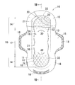
本発明に係る吸収性物品の一例を示す第1実施形態の生理用ナプキンの部分破断平面図。
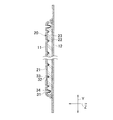
図1のII-II線断面図。
図1のIII-III線断面図。
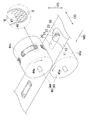
吸収性物品を製造するためのエンボス/デボス加工工程を示す説明図。
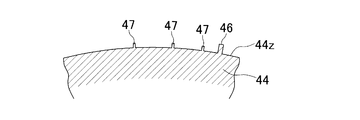
図4のV-V線拡大断面図。
第2実施形態の生理用ナプキンの部分破断平面図。
図6のVII-VII線断面図。
厚さ方向寸法評価用サンプルの写真。
厚さ方向寸法の測定例。
添付の図面を参照して、本発明に係る吸収性物品の一例である生理用ナプキンの実施形態を説明する。
<第1実施形態>
図1に示すように、本発明に係る生理用ナプキン10は、使用者の肌対向面側に位置する表面シート11と、非肌対向面側に位置する裏面シート12と、表面シート11及び裏面シート12の間に介在する吸収体20とを備える。生理用ナプキン10は縦方向Yに縦長の形状であり、縦方向中心線及び横方向中心線に関しほぼ対称である。本実施形態に係る生理用ナプキン10は、その側縁の縦方向中央部に、横方向外側に向けて凸状に延出する一対のウイング部15をさらに備える。
図1に示すように、本発明に係る生理用ナプキン10は、使用者の肌対向面側に位置する表面シート11と、非肌対向面側に位置する裏面シート12と、表面シート11及び裏面シート12の間に介在する吸収体20とを備える。生理用ナプキン10は縦方向Yに縦長の形状であり、縦方向中心線及び横方向中心線に関しほぼ対称である。本実施形態に係る生理用ナプキン10は、その側縁の縦方向中央部に、横方向外側に向けて凸状に延出する一対のウイング部15をさらに備える。
表面シート11及び裏面シート12は同形同大であり、横方向X及び縦方向Yにおける寸法がともに吸収体20よりも大きく、吸収体20の周囲に延出する周縁部13を有している。表面シート11及び裏面シート12は、周縁部13において、ホットメルト接着剤(図示せず)又は熱溶着等の、公知の手段により接合される。図1では、斜線を付して示した接合部18を有している。
表面シート11は透液性を有し、熱可塑性合成樹脂を含有する素材で形成され、例えばエアスルー繊維不織布、ポイントボンド不織布、スパンボンド不織布等の繊維不織布を好適に用いることができる。熱可塑性合成樹脂の例として、エチレンやプロピレン等のオレフィン系ポリマー、又はポリエチレンテレフタレートが挙げられるが、これらに限定されない。表面シート11は、例えば、質量が約10~50g/m2であり、厚さが約0.5~2.0mmであることが好ましい。
裏面シート12は、難透液性又は不透液性の、熱可塑性合成樹脂を含有する素材で形成され、例えば、プラスチックフィルム、又はプラスチックフィルムと繊維不織布の積層体を好適に用いることができる。繊維不織布の例として、スパンボンド・メルトブロー・スパンボンド(SMS)繊維不織布、エアスルー繊維不織布、ポイントボンド繊維不織布、スパンボンド繊維不織布が挙げられるが、これらに限定されない。熱可塑性合成樹脂には、上述の合成樹脂を用いることができる。裏面シート12は、例えば、質量が約10~50g/m2であり、厚さが約0.1~1.0mmであることが好ましい。表面シート11及び裏面シート12には、接合性上の観点などから、同種の樹脂を含有する素材を用いることが好ましい。
本実施形態のウイング部15は、表面シート11及び裏面シート12と一連に形成されている。しかし、ウイング部15を表面シート11及び裏面シート12とは別体に設けることもできる。この場合、ウイング部15を表面シート11又は裏面シート12と同種又は異種のシート材料から形成して、吸収体20の縦方向両側縁に、例えば、ホットメルト接着剤や熱溶着等の公知の手段により接合することができる。
吸収体20はほぼ矩形であり、表面シート11側に位置する第1シート21と、裏面シート12側に位置する第2シート22と、第1シート21と第2シート22との間に介在する体液吸収性の芯材23を備え、ほぼ均一の厚さに形成されている。第1シート21及び第2シート22は、ほぼ同形同大であり、その周縁部が例えばホットメルト接着剤や熱溶着等の公知の手段により互いに接合される。
第1シート21は、親水性繊維又は親水化処理の疎水性繊維から形成される透液性の繊維不織布、ティッシュペーパー、エアレイドシートを用いて形成することができる。繊維不織布を用いる場合は、エアスルー、スパンボンド、SMS等の繊維不織布を用いることができる。本実施形態の第1シート21は、エアスルー繊維不織布から形成される。エアスルー繊維不織布は、肌への液戻りを低減するうえでは、その製造が比較的容易にできるので好ましい。第1シート21の質量は、例えば約10~60g/m2であることが好ましい。第1シートは、芯材23の保形や液戻りを防ぐなどの観点から用いられていることが好ましいが、本発明にとって不可欠なものではない。第1シートが用いられない場合は、表面シート21で直接芯材23が被覆される。
第2シート22は、透液性のシート、不透液性のシートいずれかが使用されてもよく、そのシートとしては、繊維不織布、ティッシュペーパー、エアレイドシートのいずれかを採用することができる。繊維不織布が用いられる場合は、エアスルー、スパンボンド、SMS等の繊維不織布のいずれであってもよい。本実施形態の第2シート22はSMS繊維不織布から形成される。第2シート22の質量は、例えば約10~60g/m2であることが好ましい。
芯材23は、公知の吸収性ポリマー粒子、吸収性繊維又は吸湿性繊維の少なくとも一方によって形成することができる。吸収性ポリマーの例として、デンプン系、アクリル酸系、アミノ酸系ポリマーを挙げることができるが、これらに限定されない。また、吸収性繊維の例として、木材フラッフパルプ等の天然パルプ繊維、吸湿性繊維の例として、レーヨンステープル等の再生繊維、及びこれらの混合物を挙げることができるが、これらに限定されない。
表面シート11は、表面シート11と吸収体20とが重なり合う部位に、縦方向Yの両端部に半円形線及び中間両側部に波形線で形成された縦長の環状圧搾条溝31と、環状圧搾条溝31で囲まれる領域16内の縦方向Yの両端部のそれぞれに断続的に配置された複数の低圧搾凹部32を有する低圧搾域14と、低圧搾域14の間に位置する吸収中央域17とを備える。環状圧搾条溝31及び低圧搾凹部32は、表面シート11と吸収体20とを、表面シート11から裏面シート12に向かう方向に圧搾して形成される。後述するように、環状圧搾条溝31及び低圧搾凹部32はエンボス/デボス加工により形成することができる。なお、図1では芯材23に形成される圧搾痕の図示は省略されている。低圧搾凹部32を小径の円で図示しているが、低圧搾凹部32の形状は円に限定されない。
環状圧搾条溝31で囲まれる領域16は、表面シート11と吸収体20とが重なり合う部位の外周縁内側に位置する。この環状圧搾条溝31により、領域16内に排泄された体液の外部への滲出が抑制される。環状圧搾条溝31で囲まれる領域16において、両端部に形成された一対の低圧搾域14の間に位置する吸収中央域17は、生理用ナプキン10のほぼ中央部に位置し、着用時に使用者の外陰部に対向して、主たる吸収域を形成する。
本実施形態では、環状圧搾条溝31は、一対の低圧搾域14と吸収中央域17の両境界部において、生理用ナプキン10の横方向内側に向け曲線で括れる、一対の湾曲括れ部36を有する。この一対の湾曲括れ部36は、着用時において、生理用ナプキン10の中央部に位置する吸収中央域17を使用者側に盛り上げ、外陰部に密着させ易くして体液の漏れを軽減させる効果がある。一方、湾曲括れ部36の縦方向Yの両外側に位置する低圧搾域14は平面に保たれ、使用者の体の動きに順応して変形しやすい。
図2に示すように、低圧搾凹部32及び環状圧搾条溝31は、いずれも芯材23に進入するまで断面がほぼV形に圧搾して形成され、低圧搾凹部32の底部33における厚さ方向Zの寸法が、環状圧搾条溝31の底部34における厚さ方向Zの寸法より大きい。低圧搾凹部32の底部33の厚さ方向Zの寸法は、その低圧搾凹部32の周囲の厚さ方向Zの寸法の50%以上であり、60%以上であることが好ましい。環状圧搾条溝31の底部34の厚さ方向Zの寸法は、その環状圧搾条溝31の周囲の厚さ方向Zの寸法の50%未満であり、下限値の制限は特になく、エンボス/デボス加工が可能な範囲で厚さ方向Zの寸法を小さくすることができる。一例を挙げると、低圧搾凹部32及び環状圧搾条溝31が形成される生理用ナプキン10の厚さ方向Zの寸法がほぼ均一である場合、低圧搾凹部32の底部33の厚さ方向Zの寸法は、低圧搾凹部32の周囲の厚さ方向Zの寸法の約2/3であり、環状圧搾条溝31の底部34の厚さ方向Zの寸法は、環状圧搾条溝31の周囲の厚さ方向Zの寸法の約1/3であることが好ましい。
低圧搾凹部32の底部33及び環状圧搾条溝31の底部34では、第1シート21と表面シート11とが圧搾により一体化されている。別言すれば、第1シート21及び表面シート11は、低圧搾凹部32の底部33及び環状圧搾条溝31の底部34においても、破断することなく連続している。生理用ナプキン10の使用中に表面シート11が第1シート21から剥離すると、製品の捩れを誘発したり吸収性能を低下させたりするおそれがあるが、このように第1シート21と表面シート11とが圧搾により一体化されていることにより、使用者の動きによる摩擦で表面シート11が第1シート21から剥離することが抑制される。なお、第1シート21と表面シート11との一体化は、エンボス/デボス加工時の熱溶着等の、公知の手段により実施することができる。
本発明の低圧搾凹部32は、前記のように圧搾深さが相対的に小さいため、エンボス/デボス加工時に表面シート11に生じる凹凸差も相対的に小さくなる結果、使用者に不快な感覚を与えることを抑制することができる。また、低圧搾凹部32の深さが相対的に小さいことにより、低圧搾凹部32が配置された低圧搾域14の硬さの増加が抑制される結果、使用者の動きに順応した吸収性物品の変形を阻害することがない。また、本発明の低圧搾凹部32は吸収体20の芯材23内に達するまで圧搾して形成されているので、芯材23との連通性が高く、吸収体20に体液が浸透しやすい。さらに、芯材23において、低圧搾凹部32の周囲の粉砕パルプの密度が周辺に比べて高くなり、吸収した液を保持しやすくなる結果、生理用ナプキン10の吸収性が向上する。また、環状圧搾条溝31においても粉砕パルプの密度が周辺に比べて高くなり、吸収性が向上する。
図1に示すように、本実施形態では、複数の低圧搾凹部32が、縦方向Yへ対し傾斜した仮想格子線G上に配置されている。より詳しくは、複数の低圧搾凹部32は、環状圧搾条溝31で囲まれる領域16内の縦方向Yの両端部、すなわち低圧搾域14において、湾曲括れ部36と環状圧搾条溝31との間に配置され、横方向Xの内側に向け括れた湾曲括れ部36の最も括れた部分に対し横方向Xの外側となる部分にも、低圧搾凹部32が形成されている。生理用ナプキン10は、着用時に使用者の両脚から生理用ナプキン10の内側に向け横方向Xの力が加えられるため、縦方向Yに平行な皺が形成されやすい。複数の低圧搾凹部32を縦方向Yに対し傾斜した仮想格子線G上に配置することにより、縦方向Yに平行な皺の形成とが抑制され、製品の不規則な変形が防止される結果、使用感の向上や漏れの防止を図ることができる。
本実施形態では、第1シート21及び表面シート11が延伸されながら芯材23内に達するまで圧搾されて一体化されるため、仮想格子線G上において隣接する低圧搾凹部32間の第1シート21及び表面シート11が、低圧搾凹部32内に引き込まれる。このため、隣接する低圧搾凹部32間の第1シート21及び表面シート11に張力がかかり、図3に示すように、隣接する低圧搾凹部32間における厚さ方向Zの寸法がその周辺部より小さくなる。すなわち、低圧搾凹部32が配置される仮想格子線Gに沿ってわずかな窪みが生じる。これは、縦方向Yに対し傾斜した仮想格子線Gに沿って、張力がその周囲より高い部位が形成されることを意味する。この縦方向Yに対し傾斜した仮想格子線Gに沿って形成される張力が高い部位により、縦方向Yに平行な皺が形成されることが抑制されるとともに、表面シート11の第1シート21からの剥離が防止される。このような仮想格子線Gに沿った窪みの生成は、第1シート21及び表面シート11の物性、低圧搾凹部32間の距離、低圧搾凹部32の深さ等、様々な因子に依存する。しかし、このような窪みの生成の有無にかかわらず、仮想格子線G上において隣接する低圧搾凹部32間で第1シート21及び表面シート11に張力がかかる限り、前述した効果を得ることができる。
次に、図4を参照して、本発明に係る生理用ナプキン10の製造方法の一部であるエンボス/デボス加工工程について説明する。図4中、補助ローラ等の図示は省略しており、MDは機械方向を示し、CDは機械方向MDと直交する交差方向を示し、VDは、機械方向MD及び交差方向CDにそれぞれ直交する上下方向を示す。なお、機械方向MDは縦方向Yに相当し、交差方向CDは横方向Xに相当し、上下方向VDは厚さ方向Zに相当する。
エンボス/デボス加工工程では、表面シート11と、裏面シート12と、両シート11,12の間に介在する吸収体20とを含む連続ウエブ50を一方向、すなわち機械方向MDに連続的に走行させながら、一対のエンボス/デボス加工用ローラ40の間に挟持させて、表面シート11にエンボス/デボス加工する。このとき、連続ウエブ50を、表面シート11と吸収体20とが重なり合う部位が上方を向くようにして走行させる。なお、吸収体20は、第1シート21と第2シート22との間に介在する体液吸収性の芯材23を備え、ほぼ均一の厚さに形成されている。
一対のエンボス/デボス加工用ローラ40は第1ローラ44と第2ローラ45とで構成され、第1ローラ44は第2ローラ45の上方に位置する。第1ローラ44の回転軸44aと第2ローラ45の回転軸45aとは互いに平行である。第1ローラ44は、エンボス/デボス加工時に表面シート11に接するローラであり、環状圧搾条溝31を形成するための環状の第1突起部46と、環状の第1突起部46の内側に配置され、低圧搾凹部32を形成するための複数の第2突起部47とが、その周面44zから直径方向外側に向けて延び出している。図5に示すように、第1突起部46の方が、第2突起部47よりも周面44zからの高さが高い。また第1ローラ44は、温度制御手段(図示せず)により、その表面温度を制御可能に構成されている。第2ローラ45は裏面シート12側に位置する。また、第2ローラ45の周面45zは回転軸45aの軸心からの距離が一定となっており、平坦である。
エンボス/デボス加工を施す際、第1ローラ44と第2ローラ45のクリアランスを、第1突起部46及び第2突起部47により表面シート11と吸収体20とが重なり合う部位を所望の深さで圧搾できるように調整しておく。一例を挙げると、第1突起部46と第2ローラ45との間隙が0mmより大きく、約2mm以下となる範囲内でクリアランスを調整して、圧搾深さを所望の値にする。また、表面シート11と吸収体20とが重なり合う部位と、第1ローラ44の周方向に回転する第1突起部46及び第2突起部47の位置が同期するようにして、連続ウエブ50を機械方向MDに連続的に走行させる。
これにより、第1及び第2ローラ44,45の間に連続ウエブ50を一定のクリアランスで挟持させ、第1ローラ44に形成された第1突起部46及び第2突起部47のパターンを連続ウエブ50に転写して、表面シート11と吸収体20とが重なり合う部位に、環状圧搾条溝31及び複数の低圧搾凹部32を形成することができる。また、エンボス/デボス加工を施す際、第1ローラ44の温度を表面シート11と第1シート21とが熱溶着可能な温度、例えば約80~100℃にすることにより、連続ウエブ50を表面シート11から裏面シート12に向かう方向に圧搾したときに、表面シート11と第1シート21とを熱溶着により一体化することができる。このエンボス/デボス加工工程の後、所定形状の生理用ナプキン10が連続ウエブ50から切断される。
本発明の製造方法では、第1ローラ44と第2ローラ45のクリアランスを一定にして、第1ローラ44の周面44zからの高さが異なる第1突起部46及び第2突起部47を用いてエンボス/デボス加工を施す。この結果、第1ローラ44の周面44zからの高さが相対的に低い第2突起部47により形成される低圧搾凹部32の底部33における厚さ方向Zの寸法の方が、第1突起部46により形成される環状圧搾条溝31の底部34における厚さ方向Zの寸法より大きくなる。別言すれば、環状圧搾条溝31方が、低圧搾凹部32よりも深く圧搾される。すなわち、環状圧搾条溝31の方が、低圧搾凹部32より高圧縮率で圧搾される。これにより、環状圧搾条溝31が形成される部分の芯材23の密度が、低圧搾凹部32が形成される部分の芯材23の密度よりも高くなる。芯材23の密度が高い場合、体液の拡散速度が向上する。一方、芯材23の密度が相対的に低い場合、その程度にもよるが、体液の拡散速度は低下するものの、吸収保持できる体液の容量が増大する。
次に、本発明に係る生理用ナプキン10における厚さ方向Zの寸法の評価方法の一例を説明する。この評価例では、環状圧搾条溝31を形成するための環状の第1突起部46と、低圧搾凹部32を形成するための複数の第2突起部47とを有し、第1突起部46の周面44zからの高さが、第2突起部47の高さの約2倍となっている第1ローラ44を用いて作製した生理用ナプキン10を用いた。この評価で用いた生理用ナプキン10の厚さは、ほぼ均一である。
この生理用ナプキン10から、低圧搾凹部32及び環状圧搾条溝31を含む部分を切り取って、図8に示す評価用サンプルを調製した。この評価用サンプルの低圧搾凹部32及び環状圧搾条溝31を有する面を上に向けて水平な平面上に貼り付け、この平面を基準面として、非接触式のキーエンス形状測定器KS-1100を用いて、基準面に対する生理用ナプキン10の各部位の表面の高さを測定した。この評価では、基準面に対する生理用ナプキン10の表面の高さを生理用ナプキン10の「見かけ厚さ」と呼び、この見かけ厚さの比較により、生理用ナプキン10における厚さ方向Zの寸法を評価した。ここで、環状圧搾条溝31及び低圧搾凹部32の見かけ厚さの値は、これらが圧搾により形成された部分における最少の見かけ厚さの値とした。
図8に示すように、評価用サンプルの表面シート11に形成された環状圧搾条溝31は、その底面に底部圧搾部31aを有する。すなわち、環状圧搾条溝31の底面は凹凸を有し、底部圧搾部31aにおいて厚さ方向Zの寸法が最も小さくなる。また、評価用サンプルの表面シート11に形成された低圧搾凹部32は、生理用ナプキン10の縦方向に対し傾斜した仮想格子線(図示せず)上に配置されている。
図9に、キーエンス形状測定器KS-1100を用いて、図8に示した枠線内における見かけ厚さを測定した結果を示す。図9(a)は評価用サンプルを上方から見たときの見かけ厚さの分布を色調の変化で表した図であり、図9(b)は図9(a)のIXb-IXb断面における見かけ厚さの測定結果である。図9(b)に示すように、評価用サンプルでは、生理用ナプキン10の低圧搾凹部32の見かけ厚さは約1900μm、環状圧搾条溝31(底部圧搾部31a)の見かけ厚さは約1000μmであり、低圧搾凹部32の見かけ厚さの方が、環状圧搾条溝31の底部の見かけ厚さより大きい。別言すれば、低圧搾凹部32の圧搾深さの方が、環状圧搾条溝31の圧搾深さより小さい。
このようにして、低圧搾凹部32の底部における厚さ方向Zの寸法と、環状圧搾条溝31の底部における厚さ方向の寸法とを評価することができる。この評価例では、エンボス/デボス加工において第1及び第2突起部46,47で圧搾されていない部分の生理用ナプキン10の見かけ厚さは約2500~3000μmとなっている。従って、低圧搾凹部32の見かけ厚さは生理用ナプキン10の見かけ厚さの50%以上であり、環状圧搾条溝31の見かけ厚さは生理用ナプキン10の見かけ厚さの50%未満となっている。なお、図9(b)に示した例では、低圧搾凹部32及び環状圧搾条溝31の周辺の生理用ナプキン10の見かけ厚さが約2500~2700μmであるのに対し、生理用ナプキン10の端部における見かけ厚さが約3000μmとなっている。これは、エンボス/デボス加工時の圧搾により低圧搾凹部32及び環状圧搾条溝31の周辺のシート部材(第1シート21及び表面シート11)が、低圧搾凹部32及び環状圧搾条溝31内に引き込まれたためである。
<第2実施形態>
図6を参照して、本発明の第2実施形態について説明する。第2実施形態の基本的構成は第1実施形態の生理用ナプキン10と同様であるので、相違する点についてのみ以下に説明する。なお、図6では芯材23に形成される圧搾痕の図示は省略している。
図6を参照して、本発明の第2実施形態について説明する。第2実施形態の基本的構成は第1実施形態の生理用ナプキン10と同様であるので、相違する点についてのみ以下に説明する。なお、図6では芯材23に形成される圧搾痕の図示は省略している。
本実施形態に係る生理用ナプキン10は、環状圧搾条溝31で囲まれる領域16内の縦方向Yの両端部に形成された低圧搾域14と、低圧搾域14の間に位置する吸収中央域17との両境界部の吸収中央域17側に、環状圧搾条溝31から離間して互いに横方向に延びる曲線状の一対の横圧搾条溝30を備える。横圧搾条溝30は、環状圧搾条溝31と同様に、表面シート11と吸収体20とを表面シート11から裏面シート12に向かう方向に、芯材23内に達するまで圧搾して形成される。また、図7に示すように、横圧搾条溝30の底部35における厚さ方向Zの寸法より低圧搾凹部32の底部33における厚さ方向Zの寸法の方が大きい。横圧搾条溝30の底部35における厚さ方向Zの寸法は、環状圧搾条溝31の底部34における厚さ方向Zの寸法とほぼ同じにすることができるが、これに限定されない。
生理用ナプキン10の使用中、使用者の両脚から生理用ナプキン10の内側に向けて、横方向Xの力が加えられる。第2実施形態に係る生理用ナプキン10は、環状圧搾条溝31に加え、環状圧搾条溝31の内側で横方向に線状に延びる横圧搾条溝30を備えているので、生理用ナプキン10の装着時に加えられる横方向Xの力に抗することができる。これにより、生理用ナプキン10の変形が抑制され、ヨレが防止される。また、使用者の外陰部に当接する吸収中央域17は、横方向Xに延びる一対の横圧搾条溝30と、縦方向Yに延びる環状圧搾条溝31の両側部とに囲まれているため、横方向Xの力が加えられたときでも吸収中央域17の変形が有効に抑制される。この結果、吸収中央域17が使用者の外陰部に当接した状態が維持されやすい。また、横圧搾条溝30においても、環状圧搾条溝31と同様に粉砕パルプの密度が周辺に比べて高くなるため、体液吸収性が向上する。
第1実施形態と同様に、低圧搾域14に配された低圧搾凹部32は、第1シート21と表面シート11とを圧搾により一体化して形成されているので、使用者の動きによる摩擦で表面シート11が第1シート21から剥離することが防止され、また、表面シート11に生じる凹凸差が相対的に小さいため、使用者に不快な感覚を生じさせにくい。さらに低圧搾域14の硬さの増加が抑制されるので、使用者の動きに順応した吸収性物品の変形を阻害することがなく、また、縦方向Yに平行な皺が形成されることが抑制され、製品の不規則な変形が防止される結果、使用感の向上や漏れの防止を図ることができる。これらに加え、本実施形態では、低圧搾域14に変形が生じたときでも、低圧搾域14と吸収中央域17との境界部に設けられた横圧搾条溝30により、吸収中央域17に変形が伝播することを防止することができる。
本実施形態の一変形例として、一対の横圧搾条溝30の間、すなわち吸収中央域17にも低圧搾凹部32を配置することができる。吸収中央域17は使用者の外陰部に当接する部分であり、吸収中央域17に低圧搾凹部32を配置することで、表面シート11と吸収体20との連通性がよくなり、吸収体20への体液の移行が促進される。なお、本実施形態の生理用ナプキン10は、実施形態1に示した第1ローラ44に、横圧搾条溝30を形成するための突起部を追加したローラ(図示せず)を用いて、エンボス/デボス加工を施すことにより製造することができる。
本発明について実施形態に基づき説明したが、本発明はこれに限定されず、種々変更して実施することができる。例えば、環状圧搾条溝31が湾曲括れ部36を有する場合について説明したが、環状圧搾条溝31に湾曲括れ部36を設けないことができる。また、低圧搾凹部32を前記縦方向に対し傾斜した仮想格子線G上に配置する場合について説明したが、縦方向Yに平行な皺が形成されることを抑制可能な配置であれば、例えばペンローズ・タイル形式等の別の配置を採用することもできる。あるいは、芯材23を第1及び第2シート21,22の間に介在させる構成に代えて、芯材23を一枚のシート、例えばティッシュペーパーで包被することもできるし、第1シート21を省略することもできる。また、吸収体20の厚さが均一である場合について説明したが、吸収中央域17に相当する部分の吸収体20の厚さを大きくして、使用者の外陰部に密着させることもできる。また、本発明は生理用ナプキン10に限られず、例えば軽失禁パッド、パンティライナ、おりもの吸収用パッド、尿吸収パッド、紙おむつ等の吸収性物品に適用してもよい。
生理用ナプキン10を構成する部材には、特に明記されていない限りにおいて、この明細書に記載されている材料のほかに、この種の分野において通常用いられている公知の材料を制限なく用いることができる。また、この明細書において使用されている「第1」及び「第2」の用語は、同様の要素、位置等を単に区別するために用いている。
以上に記載した本発明に関する開示は、少なくとも下記事項に整理することができる。
互いに直交する縦方向と横方向と厚さ方向とを有し、着用者の肌対向面側に位置する表面シートと、着用者の非肌対向面側に位置する裏面シートと、前記表面シート及び前記裏面シートの間に介在する吸収体とを備える吸収性物品であって、前記表面シートと前記吸収体とが重なり合う部位において、前記表面シートと前記吸収体とを前記表面シートから前記裏面シートに向かう方向に圧搾して形成された縦長の環状圧搾条溝と、前記環状圧搾条溝で囲まれる領域内の前記縦方向の両端部のそれぞれに位置し、前記表面シートと前記吸収体とを前記表面シートから前記裏面シートに向かう方向に圧搾して形成された複数の低圧搾凹部を有する低圧搾域と、前記両端部に形成された前記低圧搾域の間に位置する吸収中央域とを備え、前記低圧搾凹部の底部における前記吸収性物品の前記厚さ方向の寸法が、前記環状圧搾条溝の底部における前記吸収性物品の前記厚さ方向の寸法より大きいことを特徴とする前記吸収性物品。
上記段落に開示した本発明は、少なくとも下記の実施形態を含み、実施形態は、互いに分離し又は組み合わせて採択される。
(1)前記複数の低圧搾凹部が、前記縦方向に対し傾斜し互いに交差する複数の線で構成される仮想格子線上に配置される。
(2)前記環状圧搾条溝で囲まれる前記領域内において、前記両端部に形成された前記低圧搾域と前記吸収中央域との両境界部の前記吸収中央域側に、前記環状圧搾条溝から離間して互いに前記横方向に延びる直線状及び曲線状の一方の横圧搾条溝をさらに備え、前記低圧搾凹部の前記底部における前記吸収性物品の前記厚さ方向の寸法が、前記横圧搾条溝の底部における前記吸収性物品の前記厚さ方向の寸法より大きい。
(3)前記環状圧搾条溝で囲まれる前記領域内において、前記一対の横圧搾条溝の間にも前記低圧搾凹部を有する。
(4)前記環状圧搾条溝が、前記両端部に形成された前記低圧搾域と前記吸収中央域との両境界部において、前記吸収性物品の前記横方向内側に向け括れる一対の括れ部を有する。
(5)前記一対の括れ部が湾曲している。
(6)前記低圧搾域において、前記横方向内側に向け括れる前記一対の括れ部の最も括れる部分に対し前記横方向外側となる部分にも、前記低圧搾凹部を有する。
(1)前記複数の低圧搾凹部が、前記縦方向に対し傾斜し互いに交差する複数の線で構成される仮想格子線上に配置される。
(2)前記環状圧搾条溝で囲まれる前記領域内において、前記両端部に形成された前記低圧搾域と前記吸収中央域との両境界部の前記吸収中央域側に、前記環状圧搾条溝から離間して互いに前記横方向に延びる直線状及び曲線状の一方の横圧搾条溝をさらに備え、前記低圧搾凹部の前記底部における前記吸収性物品の前記厚さ方向の寸法が、前記横圧搾条溝の底部における前記吸収性物品の前記厚さ方向の寸法より大きい。
(3)前記環状圧搾条溝で囲まれる前記領域内において、前記一対の横圧搾条溝の間にも前記低圧搾凹部を有する。
(4)前記環状圧搾条溝が、前記両端部に形成された前記低圧搾域と前記吸収中央域との両境界部において、前記吸収性物品の前記横方向内側に向け括れる一対の括れ部を有する。
(5)前記一対の括れ部が湾曲している。
(6)前記低圧搾域において、前記横方向内側に向け括れる前記一対の括れ部の最も括れる部分に対し前記横方向外側となる部分にも、前記低圧搾凹部を有する。
また、本発明の吸収性物品を製造する方法に関する開示は、少なくとも下記事項に要約することができる。
表面シートと、裏面シートと、前記表面シート及び前記裏面シートの間に介在する吸収体とを含む連続ウエブを一方向に連続的に走行させながら、一対のエンボス/デボス加工用ローラの間に挟持させて、前記表面シートにエンボス/デボス加工する工程を含み、前記一対のエンボス/デボス加工用ローラの一方のローラの周面が平坦であり、他方のローラが、その周面からローラの直径方向外側に向けて延出する、前記環状圧搾条溝を形成するための第1突起部及び前記低圧搾凹部を形成するための複数の第2突起部を備え、前記第1突起部の方が前記第2突起部よりも周面からの高さが高いことを特徴とする製造方法。
10 生理用ナプキン(吸収性物品)
11 表面シート
12 裏面シート
14 低圧搾域
16 領域
17 中央吸収域
20 吸収体
21 第1シート
22 第2シート
23 芯材
30 横圧搾条溝
31 環状圧搾条溝
32 低圧搾凹部
33 低圧搾凹部の底部
34 環状圧搾条溝の底部
35 横圧搾条溝の底部
36 湾曲括れ部
40 エンボス/デボス加工用ローラ
44z 周面
45z 周面
46 第1突起部
47 第2突起部
50 連続ウエブ
G 仮想格子線
X 横方向
Y 縦方向
Z 厚さ方向
11 表面シート
12 裏面シート
14 低圧搾域
16 領域
17 中央吸収域
20 吸収体
21 第1シート
22 第2シート
23 芯材
30 横圧搾条溝
31 環状圧搾条溝
32 低圧搾凹部
33 低圧搾凹部の底部
34 環状圧搾条溝の底部
35 横圧搾条溝の底部
36 湾曲括れ部
40 エンボス/デボス加工用ローラ
44z 周面
45z 周面
46 第1突起部
47 第2突起部
50 連続ウエブ
G 仮想格子線
X 横方向
Y 縦方向
Z 厚さ方向
Claims (8)
- 互いに直交する縦方向と横方向と厚さ方向とを有し、着用者の肌対向面側に位置する表面シートと、着用者の非肌対向面側に位置する裏面シートと、前記表面シート及び前記裏面シートの間に介在する吸収体とを備える吸収性物品であって、
前記表面シートと前記吸収体とが重なり合う部位において、前記表面シートと前記吸収体とを前記表面シートから前記裏面シートに向かう方向に圧搾して形成された縦長の環状圧搾条溝と、
前記環状圧搾条溝で囲まれる領域内の前記縦方向の両端部のそれぞれに位置し、前記表面シートと前記吸収体とを前記表面シートから前記裏面シートに向かう方向に圧搾して形成された複数の低圧搾凹部を有する低圧搾域と、
前記両端部に位置する前記低圧搾域の間に位置する吸収中央域とを備え、
前記低圧搾凹部の底部における前記吸収性物品の前記厚さ方向の寸法が、前記環状圧搾条溝の底部における前記吸収性物品の前記厚さ方向の寸法より大きいことを特徴とする前記吸収性物品。 - 前記複数の低圧搾凹部が、前記縦方向に対し傾斜し互いに交差する複数の線で構成される仮想格子線上に配置される、請求項1に記載の吸収性物品。
- 前記環状圧搾条溝で囲まれる前記領域内において、前記両端部に形成された前記低圧搾域と前記吸収中央域との両境界部の前記吸収中央域側に、前記環状圧搾条溝から離間して互いに前記横方向に延びる直線状及び曲線状の一方の横圧搾条溝をさらに備え、
前記低圧搾凹部の前記底部における前記吸収性物品の前記厚さ方向の寸法が、前記横圧搾条溝の底部における前記吸収性物品の前記厚さ方向の寸法より大きい、請求項1又は2に記載の吸収性物品。 - 前記環状圧搾条溝で囲まれる前記領域内において、前記一対の横圧搾条溝の間にも前記低圧搾凹部を有する、請求項3に記載の吸収性物品。
- 前記環状圧搾条溝が、前記両端部に形成された前記低圧搾域と前記吸収中央域との両境界部において、前記吸収性物品の前記横方向内側に向け括れる一対の括れ部を有する、請求項1から4のいずれかに記載の吸収性物品。
- 前記一対の括れ部が、湾曲している請求項1から5のいずれかに記載の吸収性物品。
- 前記低圧搾域において、前記横方向内側に向け括れる前記一対の括れ部の最も括れる部分に対し前記横方向外側となる部分にも、前記低圧搾凹部を有する、請求項5に記載の吸収性物品。
- 請求項1に記載の吸収性物品の製造方法であって、
表面シートと、裏面シートと、前記表面シート及び前記裏面シートの間に介在する吸収体とを含む連続ウエブを一方向に連続的に走行させながら、一対のエンボス/デボス加工用ローラの間に挟持させて、前記表面シートにエンボス/デボス加工する工程を含み、
前記一対のエンボス/デボス加工用ローラの一方のローラの周面が平坦であり、
他方のローラが、その周面からローラの直径方向外側に向けて延出する、前記環状圧搾条溝を形成するための第1突起部及び前記低圧搾凹部を形成するための複数の第2突起部を備え、前記第1突起部の方が前記第2突起部よりも周面からの高さが高いことを特徴とする前記製造方法。
Applications Claiming Priority (2)
| Application Number | Priority Date | Filing Date | Title |
|---|---|---|---|
| JP2012-249723 | 2012-11-13 | ||
| JP2012249723A JP2014097132A (ja) | 2012-11-13 | 2012-11-13 | 吸収性物品 |
Publications (1)
| Publication Number | Publication Date |
|---|---|
| WO2014077241A1 true WO2014077241A1 (ja) | 2014-05-22 |
Family
ID=50731153
Family Applications (1)
| Application Number | Title | Priority Date | Filing Date |
|---|---|---|---|
| PCT/JP2013/080532 Ceased WO2014077241A1 (ja) | 2012-11-13 | 2013-11-12 | 吸収性物品 |
Country Status (2)
| Country | Link |
|---|---|
| JP (1) | JP2014097132A (ja) |
| WO (1) | WO2014077241A1 (ja) |
Cited By (3)
| Publication number | Priority date | Publication date | Assignee | Title |
|---|---|---|---|---|
| TWI571249B (zh) * | 2014-10-03 | 2017-02-21 | 王子控股股份有限公司 | Absorbent items |
| US10583050B2 (en) * | 2014-11-06 | 2020-03-10 | The Procter & Gamble Company | Patterned apertured webs and methods for making the same |
| EP4548890A4 (en) * | 2023-03-17 | 2026-04-29 | Daio Seishi Kk | DISPOSABLE ITEM OF UNDERWEAR |
Families Citing this family (13)
| Publication number | Priority date | Publication date | Assignee | Title |
|---|---|---|---|---|
| JP6695668B2 (ja) * | 2014-10-03 | 2020-05-20 | 王子ホールディングス株式会社 | 吸収性物品 |
| JP6503877B2 (ja) * | 2015-05-15 | 2019-04-24 | 王子ホールディングス株式会社 | 吸収性物品 |
| JP6557004B2 (ja) * | 2014-12-10 | 2019-08-07 | 王子ホールディングス株式会社 | 吸収性物品 |
| JP6531378B2 (ja) * | 2014-12-10 | 2019-06-19 | 王子ホールディングス株式会社 | 吸収性物品 |
| NZ732546A (en) * | 2014-12-10 | 2018-05-25 | Oji Holdings Corp | Absorbent article |
| NZ732544A (en) * | 2014-12-10 | 2018-05-25 | Oji Holdings Corp | Absorbent article |
| JP6439651B2 (ja) * | 2015-10-21 | 2018-12-19 | 王子ホールディングス株式会社 | 吸収性物品 |
| JP2016112408A (ja) * | 2014-12-10 | 2016-06-23 | 王子ホールディングス株式会社 | 吸収性物品 |
| JP6558281B2 (ja) * | 2016-03-08 | 2019-08-14 | 王子ホールディングス株式会社 | 吸収性物品、その製造装置および製造方法 |
| TWI637734B (zh) * | 2015-05-15 | 2018-10-11 | 王子控股股份有限公司 | Absorbent article |
| JP6413921B2 (ja) * | 2015-05-15 | 2018-10-31 | 王子ホールディングス株式会社 | 吸収性物品 |
| JP6447396B2 (ja) * | 2015-07-09 | 2019-01-09 | 王子ホールディングス株式会社 | 吸収性物品 |
| JP2019069379A (ja) * | 2019-02-19 | 2019-05-09 | 王子ホールディングス株式会社 | 吸収性物品 |
Citations (4)
| Publication number | Priority date | Publication date | Assignee | Title |
|---|---|---|---|---|
| JPS5663430U (ja) * | 1979-10-21 | 1981-05-28 | ||
| WO2010030007A1 (ja) * | 2008-09-12 | 2010-03-18 | ユニ・チャーム株式会社 | 吸収性物品 |
| WO2010074339A1 (ja) * | 2008-12-25 | 2010-07-01 | ユニ・チャーム株式会社 | 薄型吸収性物品 |
| JP2011200568A (ja) * | 2010-03-26 | 2011-10-13 | Unicharm Corp | 吸収体の製造装置 |
Family Cites Families (3)
| Publication number | Priority date | Publication date | Assignee | Title |
|---|---|---|---|---|
| JP5711515B2 (ja) * | 2010-12-14 | 2015-04-30 | 花王株式会社 | 吸収性物品 |
| JP5904712B2 (ja) * | 2011-03-14 | 2016-04-20 | ユニ・チャーム株式会社 | 吸収性物品 |
| JP5755920B2 (ja) * | 2011-03-29 | 2015-07-29 | ユニ・チャーム株式会社 | 吸収性物品の包装体 |
-
2012
- 2012-11-13 JP JP2012249723A patent/JP2014097132A/ja active Pending
-
2013
- 2013-11-12 WO PCT/JP2013/080532 patent/WO2014077241A1/ja not_active Ceased
Patent Citations (4)
| Publication number | Priority date | Publication date | Assignee | Title |
|---|---|---|---|---|
| JPS5663430U (ja) * | 1979-10-21 | 1981-05-28 | ||
| WO2010030007A1 (ja) * | 2008-09-12 | 2010-03-18 | ユニ・チャーム株式会社 | 吸収性物品 |
| WO2010074339A1 (ja) * | 2008-12-25 | 2010-07-01 | ユニ・チャーム株式会社 | 薄型吸収性物品 |
| JP2011200568A (ja) * | 2010-03-26 | 2011-10-13 | Unicharm Corp | 吸収体の製造装置 |
Cited By (3)
| Publication number | Priority date | Publication date | Assignee | Title |
|---|---|---|---|---|
| TWI571249B (zh) * | 2014-10-03 | 2017-02-21 | 王子控股股份有限公司 | Absorbent items |
| US10583050B2 (en) * | 2014-11-06 | 2020-03-10 | The Procter & Gamble Company | Patterned apertured webs and methods for making the same |
| EP4548890A4 (en) * | 2023-03-17 | 2026-04-29 | Daio Seishi Kk | DISPOSABLE ITEM OF UNDERWEAR |
Also Published As
| Publication number | Publication date |
|---|---|
| JP2014097132A (ja) | 2014-05-29 |
Similar Documents
| Publication | Publication Date | Title |
|---|---|---|
| WO2014077241A1 (ja) | 吸収性物品 | |
| JP5839685B2 (ja) | 使い捨て吸収性物品 | |
| CN101541275B (zh) | 吸收性物品及其制造方法 | |
| JP5530693B2 (ja) | 吸収性物品 | |
| JP6257297B2 (ja) | 吸収性物品 | |
| JP2004181107A (ja) | 吸収性物品 | |
| JP6641559B2 (ja) | 吸収性物品 | |
| JP6375354B2 (ja) | 吸収性物品 | |
| JP5992285B2 (ja) | 吸収性物品 | |
| JP2015058325A (ja) | 男性用吸収パッド | |
| TWM479121U (zh) | 吸收性物品 | |
| JP6442113B1 (ja) | 吸収性物品 | |
| JP2018149004A (ja) | 吸収性物品 | |
| CN106163767A (zh) | 压花设备和方法 | |
| JP6346059B2 (ja) | 吸収性物品 | |
| JP7195096B2 (ja) | 生理用ナプキン | |
| JP2012135543A (ja) | 体液吸収性物品及びその製造方法 | |
| JP2015163130A (ja) | 吸収性物品及びその製造方法 | |
| JP6437877B2 (ja) | 吸収性物品 | |
| JP6310289B2 (ja) | 吸収性物品 | |
| JP2019146630A (ja) | 吸収性物品 | |
| JP7109942B2 (ja) | 吸収性物品 | |
| JP6152517B2 (ja) | 吸収性物品 | |
| WO2018029785A1 (ja) | 吸収性物品 | |
| JP4090461B2 (ja) | 吸収性物品の製造方法 |
Legal Events
| Date | Code | Title | Description |
|---|---|---|---|
| 121 | Ep: the epo has been informed by wipo that ep was designated in this application |
Ref document number: 13854307 Country of ref document: EP Kind code of ref document: A1 |
|
| NENP | Non-entry into the national phase |
Ref country code: DE |
|
| 122 | Ep: pct application non-entry in european phase |
Ref document number: 13854307 Country of ref document: EP Kind code of ref document: A1 |