WO2014077016A1 - 冷却塔制御装置、冷却塔制御方法、及び熱源システム - Google Patents
冷却塔制御装置、冷却塔制御方法、及び熱源システム Download PDFInfo
- Publication number
- WO2014077016A1 WO2014077016A1 PCT/JP2013/072769 JP2013072769W WO2014077016A1 WO 2014077016 A1 WO2014077016 A1 WO 2014077016A1 JP 2013072769 W JP2013072769 W JP 2013072769W WO 2014077016 A1 WO2014077016 A1 WO 2014077016A1
- Authority
- WO
- WIPO (PCT)
- Prior art keywords
- cooling
- cooling tower
- towers
- control device
- stopped
- Prior art date
- Legal status (The legal status is an assumption and is not a legal conclusion. Google has not performed a legal analysis and makes no representation as to the accuracy of the status listed.)
- Ceased
Links
Images





Classifications
-
- F—MECHANICAL ENGINEERING; LIGHTING; HEATING; WEAPONS; BLASTING
- F04—POSITIVE - DISPLACEMENT MACHINES FOR LIQUIDS; PUMPS FOR LIQUIDS OR ELASTIC FLUIDS
- F04D—NON-POSITIVE-DISPLACEMENT PUMPS
- F04D27/00—Control, e.g. regulation, of pumps, pumping installations or pumping systems specially adapted for elastic fluids
- F04D27/004—Control, e.g. regulation, of pumps, pumping installations or pumping systems specially adapted for elastic fluids by varying driving speed
-
- F—MECHANICAL ENGINEERING; LIGHTING; HEATING; WEAPONS; BLASTING
- F28—HEAT EXCHANGE IN GENERAL
- F28F—DETAILS OF HEAT-EXCHANGE AND HEAT-TRANSFER APPARATUS, OF GENERAL APPLICATION
- F28F27/00—Control arrangements or safety devices specially adapted for heat-exchange or heat-transfer apparatus
- F28F27/003—Control arrangements or safety devices specially adapted for heat-exchange or heat-transfer apparatus specially adapted for cooling towers
-
- Y—GENERAL TAGGING OF NEW TECHNOLOGICAL DEVELOPMENTS; GENERAL TAGGING OF CROSS-SECTIONAL TECHNOLOGIES SPANNING OVER SEVERAL SECTIONS OF THE IPC; TECHNICAL SUBJECTS COVERED BY FORMER USPC CROSS-REFERENCE ART COLLECTIONS [XRACs] AND DIGESTS
- Y02—TECHNOLOGIES OR APPLICATIONS FOR MITIGATION OR ADAPTATION AGAINST CLIMATE CHANGE
- Y02B—CLIMATE CHANGE MITIGATION TECHNOLOGIES RELATED TO BUILDINGS, e.g. HOUSING, HOUSE APPLIANCES OR RELATED END-USER APPLICATIONS
- Y02B30/00—Energy efficient heating, ventilation or air conditioning [HVAC]
- Y02B30/70—Efficient control or regulation technologies, e.g. for control of refrigerant flow, motor or heating
Definitions
- the present invention relates to a heat source system, and more particularly to a cooling tower control apparatus and method for controlling a cooling tower provided in the heat source system.
- Patent Documents 1 to 3 are known as methods for controlling a cooling tower in a heat source system.
- Patent Document 1 discloses a method for controlling the number of cooling towers to be started according to the load factor of the refrigerator and the outside air wet bulb temperature.
- Patent Document 2 discloses controlling the cooling water pump and the cooling tower fan based on the coefficient of performance (COP) of the heat source system.
- COP coefficient of performance
- Patent Document 3 the flow rate of cooling water flowing into the cooling tower is measured, the number of rotations of the fan is controlled for each cooling tower based on this flow rate, and the flow rate of cooling water flowing into the cooling tower is below a predetermined flow rate.
- a method for stopping the cooling tower fan is disclosed.
- the method disclosed in Patent Document 1 determines the required cooling capacity and determines the number of cooling towers to be activated accordingly, and therefore exhibits the cooling capacity for improving the refrigerator COP. Although possible, it is difficult to save energy in the cooling tower itself.
- the method disclosed in Patent Document 2 since the cooling water outlet temperature is set based on the heat source COP, the cooling capacity required for the cooling tower can be defined. However, there is no disclosure about the specific operation method of the cooling tower.
- Patent Document 3 The method disclosed in Patent Document 3 is intended to save energy in each cooling tower, and does not consider macro energy saving as the whole cooling tower.
- a method for controlling the number of cooling towers based on the cooling water temperature in the heat source system is known.
- this method is also a simple control in which the number of startups is increased when the cooling water temperature is high, and the number of startups is reduced when the cooling water temperature is low, and it is not intended to save energy in the cooling tower. .
- An object of the present invention is to provide a cooling tower control device, a cooling tower control method, and a heat source system.
- a first aspect of the present invention is a cooling tower control device applied to a heat source system including a plurality of cooling towers connected in parallel with a common refrigerator, and at the time of startup of the heat source system, all the cooling It is a cooling tower control apparatus which starts a tower.
- all the cooling towers are started when the heat source system is started. In other words, all cooling tower fans are rotated.
- the number of fan rotations per unit can be reduced, and power consumption can be reduced. Can be suppressed. Energy saving can be easily achieved by a simple process of starting all the cooling towers without referring to the refrigerator load and the required cooling capacity of the entire cooling tower.
- the cooling tower control device stops any one of the cooling towers when a state in which the rotational speed of the fan in the cooling tower in operation is equal to or lower than a pre-registered minimum rotational speed is maintained for a predetermined period. It is also possible to make it.
- the minimum rotational speed is, for example, a lower limit rotational speed set in the specification of the cooling tower, or a value having an arbitrary margin.
- the cooling tower control device operates the fans of the number of cooling towers, which is one added to the number of currently operating cooling towers, at the minimum number of rotations in a state where at least one of the refrigerators is stopped.
- a determination means for determining whether or not a state where the required cooling capacity for the entire cooling tower is equal to or higher than the cooling capacity estimated by the estimation means has been maintained for a predetermined period. When the determination means determines that the state has been maintained for a predetermined period, one of the cooling towers out of operation may be activated.
- the fans of each cooling tower are operated at the minimum rotation speed or more even if one of them is added. Since additional activation is performed after confirming in advance, it is possible to prevent the cooling tower from being frequently started and stopped and to stabilize the entire heat source system. By performing such control, as many cooling towers as possible can be activated. Thereby, power consumption can be suppressed effectively and energy saving can be achieved.
- the cooling tower control device has startup priorities set in descending order of cooling efficiency of the cooling tower, and determines the cooling tower to be stopped and the cooling tower to be restarted based on the startup priority. It is good to do.
- the cooling tower control device may rotate the fans of the cooling towers at the same rotational speed regardless of the cooling efficiency of the cooling towers.
- the fan speed of the cooling tower with relatively high cooling efficiency is set to a higher value so that the cooling efficiency is relative. It was confirmed that even if the fan speed of the cooling tower is set to be low, the effect of the power consumption due to the difference in the speed does not appear so remarkably. Therefore, power consumption can be suppressed by simple control by giving the same rotational speed command to all fans regardless of the cooling efficiency.
- the cooling tower control device activates any one of the cooling towers whose operation has been stopped when cooling water temperature is maintained at a predetermined threshold value or more for a predetermined period, and cools the cooling tower. When the water temperature is kept below a predetermined threshold for a predetermined period, any one of the cooling towers in operation may be stopped.
- the cooling water can be directly controlled within a predetermined range, and the cooling water system and the refrigerator can be stably operated. It becomes.
- the cooling tower control device may stop any one of the cooling towers in operation when the bypass valve is maintained at a predetermined opening or more for a predetermined period.
- the cooling tower is stopped in consideration of the cooling water bypass valve, so that inefficient excessive operation of the cooling tower can be avoided. That is, the power consumption of the cooling tower can be suppressed.
- the cooling tower control device is configured such that when one of the cooling towers that has stopped operating is maintained for a predetermined period in which the rotation speed of the fan in the cooling tower is equal to or higher than a predetermined threshold, It is good also as starting a tower.
- the second aspect of the present invention is a heat source system including a refrigerator, a plurality of cooling towers connected in parallel to the refrigerator, and any one of the above cooling tower control devices.
- a third aspect of the present invention is a cooling tower control method applied to a heat source system including a plurality of cooling towers connected in parallel to a common refrigerator, and at the time of startup of the heat source system, A cooling tower control method for starting the cooling tower.
- FIG. 1 is a diagram schematically showing a configuration of a heat source system according to an embodiment of the present invention.
- the heat source system 1 is connected in parallel to the refrigerator 2 and the refrigerator 2, and cools and supplies the cooling water heated by being used in the refrigerator 2 to the refrigerator 2 3.
- Main cooling towers 3a, 3b, and 3c and a cooling tower control device 4 that controls the cooling towers 3a, 3b, and 3c are provided as main components.
- FIG. 1 illustrates a case where three cooling towers are provided, the number of cooling towers is not limited.
- the cooling water used in the refrigerator 2 is supplied to the cooling towers 3a, 3b, and 3c via the forward piping 6.
- the cooling water cooled by the cooling towers 3a, 3b, 3c is sent to the refrigerator 2 through the return pipe 7.
- the forward pipe 6 is provided with a water supply header 8, and the return pipe 7 is provided with a return water header 9.
- a cooling water pump 10 is provided downstream of the return water header 9 in the return pipe 7 in the cooling water flow. By controlling the rotation speed of the cooling water pump 10, the flow rate of the circulating cooling water is adjusted.
- a bypass pipe 12 is provided between the water supply header 8 and the return water header 9.
- the bypass pipe 12 is provided with a cooling water bypass valve (bypass valve) 13. By adjusting the opening degree of the cooling water bypass valve 13, the flow rate of bypassing from the water supply header 8 to the return water header 9 is adjusted.
- the cooling water after heat exchange in the refrigerator 2 and the flow rate sensor 15 that measures the flow rate Fc of the cooling water that has flowed out of the refrigerator 2 is located upstream of the water supply header 8 in the cooling water flow. Is provided with a temperature sensor 16 for measuring the temperature (hereinafter referred to as “cooling tower inlet temperature Ti”).
- the temperature of the cooling water cooled in the cooling towers 3 a, 3 b, 3 c and flowing into the refrigerator 2 hereinafter referred to as “cooling tower outlet temperature To”.
- the temperature sensor 17 is provided for measuring. The measured values of the flow sensor 15 and the temperature sensors 16 and 17 are output to the cooling tower control device 4.
- the cooling tower control device 4 controls the rotation speed of the fans of the cooling towers 3a, 3b, and 3c using the measured values from the flow rate sensor 15 and the temperature sensors 16 and 17, and performs start / stop control as described below.
- the cooling tower control device 4 is, for example, a computer, and communicates information with a main storage device such as a CPU (Central Processing Unit) and a RAM (Random Access Memory), an auxiliary storage device, and an external device. It has a communication device for sending and receiving.
- the auxiliary storage device is a computer-readable recording medium, such as a magnetic disk, a magneto-optical disk, a CD-ROM, a DVD-ROM, or a semiconductor memory.
- Various programs are stored in the auxiliary storage device, and various processes are realized by the CPU reading and executing the program from the auxiliary storage device to the main storage device.
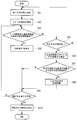
- step SA1 when receiving the cooling tower start command, the cooling tower control device 4 starts all the cooling towers (step SA1). Thereby, the cooling towers 3a, 3b, and 3c are activated, and cooling of the cooling water is started by the rotation of the fan.
- the cooling tower control device 4 starts the rotational speed control of the fans included in the cooling towers 3a, 3b, and 3c (step SA2).
- the rotation speed of the fan of each cooling tower 3a, 3b, 3c is controlled so that the cooling tower exit temperature To becomes set temperature.
- the rotational speeds of the fans included in the cooling towers 3a, 3b, and 3c are controlled to the same rotational speed.
- the cooling tower control device 4 determines whether or not the state where the rotational speed of the fan is equal to or lower than the preset minimum rotational speed is maintained for a predetermined period (for example, 60 seconds) (step SA3).
- the minimum rotational speed is a lower limit rotational speed that is generally set in order to prevent operation at an extremely low rotational speed.
- the lower limit rotational speed may be a value with an arbitrary margin.
- step SA3 determines whether or not that the state where the rotational speed of the fan is equal to or lower than the minimum rotational speed has not been maintained for a predetermined period ("NO" in step SA3). It is determined whether or not (step SA5). As a result, if there is no cooling tower that has been stopped, the process returns to step SA1, and if there is a cooling tower that has been stopped, the number of cooling towers that have been added to the number of cooling towers that are in operation is rotated to the minimum.
- the cooling capacity when operating with a number is estimated (step SA6). For example, when N cooling towers are in operation, the cooling capacity is estimated as follows.
- the cooling tower control device 4 has a table in which the cooling capacity, the outdoor wet bulb temperature, and the cooling water flow rate are associated with each cooling tower when the cooling tower is operated at the minimum rotation speed. ing. Then, the cooling tower control device 4 acquires the cooling capacity corresponding to the current cooling water flow rate and the outside air wet bulb temperature by using the table corresponding to the cooling tower that is in operation and additionally activated, and acquires the acquired cooling capacity. Is added to estimate the cooling tower capacity when one additional unit is started.
- step SA7 it is determined whether or not the state where the required cooling capacity for the entire cooling tower is equal to or higher than the cooling capacity estimated in step SA6 is maintained for a predetermined period (for example, 300 sec) (step SA7).
- a predetermined period for example, 300 sec
- step SA8 one of the cooling towers whose operation has been stopped is additionally activated
- step SA9 it is determined whether or not an operation stop command has been received. If not received, the process returns to step SA3 to repeat the above processing. On the other hand, when the operation stop command is received, the operation of the cooling tower that is being operated is stopped (step SA10), and the process is terminated.
- FIG. 3 shows the relationship between the power consumption of the cooling tower, the cooling capacity, and the cooling efficiency with respect to the rotational speed of the fan.
- the cooling capacity of the cooling tower is represented by the following equation (1)
- the cooling efficiency is represented by the following equation (2).
- ⁇ T is the difference between the cooling tower inlet temperature and the cooling tower outlet temperature
- Fc is the cooling water flow rate
- c is the specific heat
- FIG. 4 shows the relationship between the cooling capacity and power consumption for each number of startups, assuming the same cooling water flow path to each cooling tower.
- FIG. 4 shows the relationship between cooling capacity and power consumption when one cooling tower is operated, when two cooling towers are operated, and when three cooling towers are operated. Yes.
- Each plot in FIG. 4 is a plot when combining a plurality of rotation speeds of each cooling tower.
- FIG. 4 shows a plot of the power consumption and the cooling capacity in each pattern by setting a plurality of rotation speed distribution ratios in order to obtain the same cooling capacity. And the curve shown in FIG. 4 connects the plot when the rotation speed of each cooling tower is made the same.
- FIG. 4 shows the result when the cooling tower activation is the cooling tower water flow, but the same result was obtained even when the cooling tower activation was the cooling tower fan rotation and the cooling tower water flow. . Thereby, in any case, when each cooling tower was operated by the same rotation speed, it turned out that power consumption can be reduced most.
- the power consumption can be reduced as the number of activated units increases. For example, when trying to obtain a cooling capacity of 2000 [kW] with three cooling towers, the power consumption is about 1 [kW], whereas when trying to obtain with 2 cooling towers, More than twice the power consumption, and when trying to obtain it with a single cooling tower, it shows nearly seven times the power consumption.
- the number of cooling towers to be started is increased to keep the rotational speed of each fan at a low rotational speed, and the rotational speed of each cooling tower is kept constant. It can be seen that such operation can minimize the power consumption in the entire cooling tower. Therefore, like the cooling tower control device, the cooling tower control method, and the heat source system according to the present embodiment, when the cooling tower is started, by starting all the cooling towers that can be operated, Energy saving can be achieved.
- the cooling tower control device when the number of rotations of the fan is equal to or lower than the minimum number of rotations, the number of operating cooling towers is reduced by one. It is possible to avoid the operation of the fan in a region below a few.
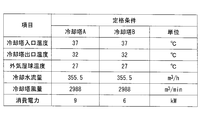
- the rotation speed of the fan included in each cooling tower is controlled to the same rotation speed regardless of the cooling efficiency that each cooling tower can exhibit. Is done. For example, as shown in FIG. 5, assuming two cooling towers with different cooling efficiencies, the result of simulating the relationship between cooling capacity and power consumption is shown in FIG. This simulation result is obtained based on the relationship that the power consumption is proportional to the cube of the rotation speed.
- cooling capacity of the cooling tower A is optimized at an optimum ratio.
- cooling tower A rotational speed cooling tower B rotational speed
- the power consumption during the rated operation of the cooling tower A is set to 9 kW
- the power consumption during the rated operation of the cooling tower B is set to 6 kW.
- step SA4 in FIG. 2 when only one unit is activated from FIGS. 5 and 6, it is clear that the cooling tower B consumes less power than the cooling tower A ("only cooling tower A is operated" in FIG. 6). And “Operation of cooling tower B only”). Therefore, when one cooling tower is stopped due to a decrease in the required cooling capacity (step SA4 in FIG. 2), the cooling tower with low cooling efficiency may be stopped preferentially. Conversely, when one additional cooling tower is activated due to an increase in the required cooling capacity (step SA8 in FIG. 2), the cooling tower with high cooling efficiency may be activated preferentially. In this way, by determining the priority according to the cooling efficiency and performing the start / stop control based on this priority, for example, since the required cooling capacity is low, the operation with only one cooling tower is possible. When the output is sufficient, power consumption can be suppressed.
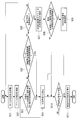
- FIG. 1 the process performed by the cooling tower control apparatus 4 which concerns on 2nd Embodiment of this invention is demonstrated using FIG.
- a process for starting or stopping the cooling tower in consideration of the cooling water temperature is added to the first embodiment described above. Since other points are the same as those in the first embodiment, description thereof will be omitted.
- the cooling tower control device 4 starts all the cooling towers (step SB1). Thereby, the cooling towers 3a, 3b, and 3c are activated, and cooling of the cooling water is started by the rotation of the fan.
- the cooling tower control device 4 starts the rotational speed control of the fans included in the cooling towers 3a, 3b, and 3c (step SB2).
- the rotation speed of the fan of each cooling tower 3a, 3b, 3c is controlled so that the cooling tower exit temperature To becomes set temperature.
- the rotational speeds of the fans included in the cooling towers 3a, 3b, and 3c are controlled to the same rotational speed.
- the cooling tower control device 4 determines whether or not the state where the cooling water temperature, that is, the cooling tower outlet temperature To is equal to or lower than the preset designated temperature 1 is maintained for a predetermined period (step SB3).
- the designated temperature 1 is a predetermined threshold value serving as a reference for forced cooling tower cooling, and is a value based on the lower limit value of the cooling water temperature determined by the refrigerator.
- step SB3 when it is determined in step SB3 that the state where the cooling water temperature is equal to or lower than the specified temperature 1 is not maintained for a predetermined period ("NO" in step SB3), the cooling tower control device 4 rotates the fan. It is determined whether or not a state where the number is equal to or less than a preset minimum rotational speed is maintained for a predetermined period (for example, 60 seconds) (step SB5).
- the minimum rotational speed is a lower limit rotational speed that is generally set in order to prevent operation at an extremely low rotational speed.
- the lower limit rotational speed may be a value with an arbitrary margin.
- step SB5 determines that the state where the rotational speed of the fan is equal to or lower than the minimum rotational speed has not been maintained for a predetermined period of time ("NO" in step SB5). It is determined whether or not (step SB6). As a result, when there is no cooling tower that is stopped, the process returns to step SB1, and when there is a cooling tower that is stopped, the cooling tower control device 4 determines that the cooling water temperature, that is, the cooling tower outlet temperature To is It is determined whether or not a state where the preset temperature is 2 or more is maintained for a predetermined period (step SB7).
- the designated temperature 2 is a predetermined threshold value that is a reference for forced additional activation of the cooling tower, and is a value obtained by adding an arbitrary margin to the outside air wet bulb temperature or the outside air dry bulb temperature.
- step SB7 determines whether the state where the cooling water temperature is equal to or higher than the specified temperature 2 has not been maintained for a predetermined period ("NO" in step SB7). If it is determined in step SB7 that the state where the cooling water temperature is equal to or higher than the specified temperature 2 has not been maintained for a predetermined period ("NO" in step SB7), one is added to the number of cooling towers in operation. The cooling capacity when the number of cooling towers operated at the minimum number of revolutions is estimated (step SB9).
- step SB10 it is determined whether or not the state where the required cooling capacity for the entire cooling tower is equal to or higher than the cooling capacity estimated in step SB9 is maintained for a predetermined period (for example, 300 sec) (step SB10).
- a predetermined period for example, 300 sec
- step SB8 one of the cooling towers whose operation is stopped is additionally activated
- step SB11 it is determined whether or not an operation stop command has been received. If not received, the process returns to step SB3 and the above processing is repeated. On the other hand, when the operation stop command is received, the operation of the cooling tower that is operating is stopped (step SB12), and the process is terminated.
- the cooling tower is started or stopped in consideration of the cooling water temperature.
- the cooling water can be directly controlled within a predetermined range, and the cooling water system and the refrigerator can be stably operated.
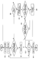
- FIG. 1 the process performed by the cooling tower control apparatus 4 which concerns on 3rd Embodiment of this invention is demonstrated using FIG.
- the present embodiment is obtained by adding a cooling tower stop process in consideration of the opening degree of the cooling water bypass valve to the first embodiment described above. Since other points are the same as those in the first embodiment, description thereof will be omitted.
- the cooling tower control device 4 starts all the cooling towers (step SC1). Thereby, the cooling towers 3a, 3b, and 3c are activated, and cooling of the cooling water is started by the rotation of the fan.
- the cooling tower control device 4 starts the rotational speed control of the fans included in the cooling towers 3a, 3b, and 3c (step SC2).
- the rotation speed of the fan of each cooling tower 3a, 3b, 3c is controlled so that the cooling tower exit temperature To becomes set temperature.
- the rotational speeds of the fans included in the cooling towers 3a, 3b, and 3c are controlled to the same rotational speed.
- the cooling tower control device 4 determines whether or not the state where the opening degree of the cooling water bypass valve 13 is equal to or larger than a preset opening degree is maintained for a predetermined period (step SC3).
- the designated opening is a predetermined threshold value that serves as a reference for forced cooling tower cooling.
- step SC3 when it is determined in step SC3 that the state where the opening degree of the cooling water bypass valve 13 is equal to or greater than the specified opening degree is not maintained for a predetermined period ("NO" in step SC3), the cooling tower control device 4 Determines whether or not the state where the rotational speed of the fan is equal to or lower than a preset minimum rotational speed is maintained for a predetermined period (for example, 60 sec) (step SC5).
- the minimum rotational speed is a lower limit rotational speed that is generally set in order to prevent operation at an extremely low rotational speed.
- the lower limit rotational speed may be a value with an arbitrary margin.
- step SC5 determines whether or not there is a cooling tower that has been stopped. Is determined (step SC6). As a result, if there is no cooling tower that has been stopped, the process returns to step SC1, and if there is a cooling tower that has been stopped, the number of cooling towers, which is one added to the number of cooling towers that are in operation, is rotated to the minimum. The cooling capacity when operating with a number is estimated (step SC7).
- step SC8 it is determined whether or not the state where the required cooling capacity for the entire cooling tower is equal to or higher than the cooling capacity estimated in step SC7 is maintained for a predetermined period (for example, 300 sec) (step SC8).
- a predetermined period for example, 300 sec
- step SC9 it is determined whether or not an operation stop command has been received. If it has not been received, the process returns to step SC3 to repeat the above processing.
- step SC11 the operation of the cooling tower that is being operated is stopped (step SC11), and the process is terminated.
- the cooling tower is stopped in consideration of the cooling water bypass valve 13. Thereby, the inefficient excessive operation of a cooling tower can be avoided and it becomes possible to suppress the power consumption of a cooling tower.
- FIG. 1 the process performed by the cooling tower control apparatus 4 which concerns on 4th Embodiment of this invention is demonstrated using FIG.
- the present embodiment is obtained by adding cooling tower activation processing in consideration of cooling tower degradation to the first embodiment described above. Since other points are the same as those in the first embodiment, description thereof will be omitted.
- the cooling tower control device 4 starts all the cooling towers (step SD1). Thereby, the cooling towers 3a, 3b, and 3c are activated, and cooling of the cooling water is started by the rotation of the fan.
- the cooling tower control device 4 starts controlling the rotational speed of the fans included in the cooling towers 3a, 3b, and 3c (step SD2).
- the rotation speed of the fan of each cooling tower 3a, 3b, 3c is controlled so that the cooling tower exit temperature To becomes set temperature.
- the rotational speeds of the fans included in the cooling towers 3a, 3b, and 3c are controlled to the same rotational speed.
- the cooling tower control device 4 determines whether or not the state where the rotational speed of the fan is equal to or lower than the preset minimum rotational speed is maintained for a predetermined period (for example, 60 seconds) (step SD3).
- the minimum rotational speed is a lower limit rotational speed that is generally set in order to prevent operation at an extremely low rotational speed.
- the lower limit rotational speed may be a value with an arbitrary margin.
- step SD3 determines whether or not there is a cooling tower that has been stopped. Is determined (step SD5). As a result, if there is no cooling tower that has been stopped, the process returns to step SD1, and if there is a cooling tower that has been stopped, the number of cooling towers is added to the number of cooling towers that are in operation. The cooling capacity when operating with a number is estimated (step SD6).
- step SD7 it is determined whether or not the state where the required cooling capacity for the entire cooling tower is equal to or higher than the cooling capacity estimated in step SD6 is maintained for a predetermined period (for example, 300 sec) (step SD7).
- a predetermined period for example, 300 sec
- step SD8 one of the cooling towers whose operation is stopped is additionally activated (step SD8), and the process proceeds to step SD10.
- step SD7 when it is determined in step SD7 that the state where the required cooling capacity for the entire cooling tower is equal to or greater than the estimated cooling capacity has not been maintained for a predetermined period, the cooling tower control device 4 sets the rotational speed of the fan in advance.
- step SD9 It is determined whether or not the state that is equal to or higher than the designated rotational speed is maintained for a predetermined period (for example, 60 sec) (step SD9).
- the designated rotational speed is a rotational speed set as a value for determining deterioration in order to prevent continuation of operation at a high rotational speed when the cooling tower performance deteriorates.
- step SD10 it is determined whether or not an operation stop command has been received. If not received, the process returns to step SD3 to repeat the above processing. On the other hand, when the operation stop command is received, the operation of the cooling tower that is operating is stopped (step SD11), and the process is terminated.
- the cooling tower is activated in consideration of the deterioration of the cooling tower. As a result, it is possible to avoid continuing inefficient operation at a high fan rotation speed and to suppress power consumption of the cooling tower.
Landscapes
- Engineering & Computer Science (AREA)
- Mechanical Engineering (AREA)
- General Engineering & Computer Science (AREA)
- Physics & Mathematics (AREA)
- Thermal Sciences (AREA)
- Air Conditioning Control Device (AREA)
- Other Air-Conditioning Systems (AREA)
Abstract
Description
すなわち、特許文献1に開示される方法は、必要とされる冷却能力を決定し、それに応じて冷却塔の起動台数を決定するため、冷凍機COPを向上させるための冷却能力を発揮することは可能であるが、冷却塔自身の省エネルギー化を図ることは難しい。
特許文献2に開示された方法では、熱源COPに基づいて冷却水出口温度を設定するため、冷却塔に要求される冷却能力は定義できる。しかし、冷却塔の具体的な運転方法については開示がない。
一般的に、熱源システム内の冷却水温度に基づいて、冷却塔台数を制御する方法が知られている。しかしながら、この方法も、冷却水温度が高くなれば起動台数を増加させ、冷却水温度が低くなれば起動台数を減少させるという単純な制御であり、冷却塔の省エネルギー化を考慮したものではなかった。
最低回転数とは、例えば、冷却塔の仕様で設定されている下限回転数、またはそれに任意のマージンを持たせた値である。
図1は、本発明の一実施形態に係る熱源システムの構成を概略的に示した図である。図1に示すように、熱源システム1は、冷凍機2と、冷凍機2と並列に接続され、冷凍機2で用いられることにより加熱された冷却水を冷却して冷凍機2へ供給する3台の冷却塔3a、3b、3cと、冷却塔3a、3b、3cの制御を行う冷却塔制御装置4とを主な構成として備えている。図1では、3台の冷却塔を備えている場合を例示しているが、冷却塔の台数については限定されない。
流量センサ15、温度センサ16、17の計測値は冷却塔制御装置4へ出力される。
例えば、冷却塔制御装置4は、例えば、コンピュータであり、CPU(中央演算処理装置)、RAM(Random Access Memory)等の主記憶装置、補助記憶装置、外部の機器と通信を行うことにより情報の授受を行う通信装置などを備えている。
以下、本発明の第1実施形態に係る冷却塔制御装置4によって実行される処理について、図2を用いて説明する。
まず、冷却塔制御装置4は、冷却塔の起動指令を受信すると、全台数の冷却塔を起動させる(ステップSA1)。これにより、冷却塔3a、3b、3cは起動し、ファンが回転することにより、冷却水の冷却が開始される。
この結果、ファンの回転数が最低回転数以下である状態が所定期間維持されていた場合には、冷却塔を1台停止させ(ステップSA4)、ステップSA9に進む。
例えば、冷却塔制御装置4は、各冷却塔に対応して、その冷却塔を最低回転数で運転させた場合の冷却能力と外気湿球温度及び冷却水流量とが関連付けられたテーブルを保有している。そして、冷却塔制御装置4は、運転中及び追加起動させる冷却塔に対応する上記テーブルを用いて、現在の冷却水流量と外気湿球温度に対応する冷却能力をそれぞれ取得し、取得した冷却能力を合計することで、1台追加起動させた場合の冷却塔能力を推定する。
一方、上記ステップSA7において、上記状態が所定期間維持されていないと判定した場合には、ステップSA9に進む。
ステップSA9では、運転停止指令を受信したか否かを判定し、受信していなかった場合には、ステップSA3に戻り、上記処理を繰り返し行う。一方、運転停止指令を受信した場合には、運転中である冷却塔を運転停止させ(ステップSA10)、処理を終了する。
冷却効率=冷却能力/消費電力 (2)
したがって、本実施形態に係る冷却塔制御装置、冷却塔制御方法、及び熱源システムのように、冷却塔の起動時において、稼働可能な全台数の冷却塔を起動させることにより、冷却塔全体としての省エネルギー化を図ることができる。
例えば、図5に示すように、冷却効率の異なる2台の冷却塔を想定し、冷却能力と消費電力の関係をシミュレーションした結果を図6に示す。このシミュレーション結果は、消費電力が回転数の3乗に比例するという関係に基づいて得たものである。
以下、本発明の第2実施形態に係る冷却塔制御装置4によって実行される処理について、図7を用いて説明する。
本実施形態は、上記した第1実施形態に冷却水温度を考慮した冷却塔の起動または停止の処理を追加したものである。その他の点については第1実施形態と同様であるので、説明は省略する。
まず、冷却塔制御装置4は、冷却塔の起動指令を受信すると、全台数の冷却塔を起動させる(ステップSB1)。これにより、冷却塔3a、3b、3cは起動し、ファンが回転することにより、冷却水の冷却が開始される。
この結果、冷却水温度が指定温度1以下である状態が所定期間維持されていた場合には、冷却塔を1台停止させ(ステップSB4)、ステップSB11に進む。
この結果、ファンの回転数が最低回転数以下である状態が所定期間維持されていた場合には、冷却塔を1台停止させ(ステップSB4)、ステップSB11に進む。
この結果、冷却水温度が指定温度2以上である状態が所定期間維持されていた場合には、冷却塔を1台追加起動させ(ステップSB8)、ステップSB11に進む。
一方、上記ステップSB10において、上記状態が所定期間維持されていないと判定した場合には、ステップSB11に進む。
ステップSB11では、運転停止指令を受信したか否かを判定し、受信していなかった場合には、ステップSB3に戻り、上記処理を繰り返し行う。一方、運転停止指令を受信した場合には、運転中である冷却塔を運転停止させ(ステップSB12)、処理を終了する。
以下、本発明の第3実施形態に係る冷却塔制御装置4によって実行される処理について、図8を用いて説明する。
本実施形態は、上記した第1実施形態に冷却水バイパス弁の開度を考慮した冷却塔の停止の処理を追加したものである。その他の点については第1実施形態と同様であるので、説明は省略する。
まず、冷却塔制御装置4は、冷却塔の起動指令を受信すると、全台数の冷却塔を起動させる(ステップSC1)。これにより、冷却塔3a、3b、3cは起動し、ファンが回転することにより、冷却水の冷却が開始される。
この結果、冷却水バイパス弁13の開度が指定開度以上である状態が所定期間維持されていた場合には、冷却塔を1台停止させ(ステップSC4)、ステップSC10に進む。
この結果、ファンの回転数が最低回転数以下である状態が所定期間維持されていた場合には、冷却塔を1台停止させ(ステップSC4)、ステップSC10に進む。
一方、上記ステップSC8において、上記状態が所定期間維持されていないと判定した場合には、ステップSC10に進む。
ステップSC10では、運転停止指令を受信したか否かを判定し、受信していなかった場合には、ステップSC3に戻り、上記処理を繰り返し行う。一方、運転停止指令を受信した場合には、運転中である冷却塔を運転停止させ(ステップSC11)、処理を終了する。
以下、本発明の第4実施形態に係る冷却塔制御装置4によって実行される処理について、図9を用いて説明する。
本実施形態は、上記した第1実施形態に冷却塔の劣化を考慮した冷却塔の起動の処理を追加したものである。その他の点については第1実施形態と同様であるので、説明は省略する。
まず、冷却塔制御装置4は、冷却塔の起動指令を受信すると、全台数の冷却塔を起動させる(ステップSD1)。これにより、冷却塔3a、3b、3cは起動し、ファンが回転することにより、冷却水の冷却が開始される。
この結果、ファンの回転数が最低回転数以下である状態が所定期間維持されていた場合には、冷却塔を1台停止させ(ステップSD4)、ステップSD10に進む。
一方、上記ステップSD7において、冷却塔全体に対する要求冷却能力が推定冷却能力以上である状態が所定期間維持されていないと判定した場合には、冷却塔制御装置4は、ファンの回転数が予め設定されている指定回転数以上である状態が所定期間(例えば、60sec)維持されているか否かを判定する(ステップSD9)。ここで、指定回転数とは、冷却塔性能が劣化した場合に高い回転数での運転の継続を防止するために、劣化を判定する値として設定されている回転数である。
この結果、ファンの回転数が指定回転数以上である状態が所定期間維持されていた場合には、冷却塔を1台追加起動させ(ステップSD8)、ステップSD10に進む。
一方、上記ステップSD9において、上記状態が所定期間維持されていないと判定した場合には、ステップSD10に進む。
ステップSD10では、運転停止指令を受信したか否かを判定し、受信していなかった場合には、ステップSD3に戻り、上記処理を繰り返し行う。一方、運転停止指令を受信した場合には、運転中である冷却塔を運転停止させ(ステップSD11)、処理を終了する。
2 冷凍機
3a、3b、3c 冷却塔
4 冷却塔制御装置
6 往き配管
7 還り配管
8 送水ヘッダ
9 還水ヘッダ
10 冷却水ポンプ
12 バイパス配管
13 冷却水バイパス弁(バイパス弁)
15 流量センサ
16、17 温度センサ
Claims (10)
- 共通の冷凍機と並列に接続された複数の冷却塔を備える熱源システムに適用される冷却塔制御装置であって、
前記熱源システムの起動時において、全ての前記冷却塔を起動させる冷却塔制御装置。 - 運転中の前記冷却塔におけるファンの回転数が予め登録されている最低回転数以下である状態が所定期間維持された場合に、いずれか1台の前記冷却塔を停止させる請求項1に記載の冷却塔制御装置。
- 少なくとも1台の前記冷凍機が停止している状態において、
現在運転中の冷却塔台数に1台加算した台数の冷却塔の各前記ファンを前記最低回転数で運転させたときの冷却能力を推定する推定手段と、
冷却塔全体に対する要求冷却能力が前記推定手段によって推定された冷却能力以上である状態が、所定期間維持されたか否かを判定する判定手段と
を備え、
前記判定手段によって、前記状態が所定期間維持されたと判定された場合に、運転を停止している前記冷却塔のうち1台の前記冷却塔を起動させる請求項2に記載の冷却塔制御装置。 - 前記冷却塔の冷却効率が高い順に設定された起動優先度を有し、前記起動優先度に基づいて、停止させる前記冷却塔、及び、再起動させる前記冷却塔を決定する請求項3に記載の冷却塔制御装置。
- 前記冷却塔の冷却効率にかかわらず、各前記冷却塔のファンを同一回転数で回転させる請求項1から請求項4のいずれかに記載の冷却塔制御装置。
- 冷却水温度が所定の閾値以上の状態を所定期間維持された場合に、運転を停止している前記冷却塔のうちいずれか1台の前記冷却塔を起動させ、冷却水温度が所定の閾値以下の状態を所定期間維持された場合に、運転中の前記冷却塔のうちいずれか1台の前記冷却塔を停止させる請求項1から5のいずれかに記載の冷却塔制御装置。
- バイパス弁が所定の開度以上の状態を所定期間維持された場合に、運転中の前記冷却塔のうちいずれか1台の前記冷却塔を停止させる請求項1から6のいずれかに記載の冷却塔制御装置。
- 前記冷却塔における前記ファンの回転数が所定の閾値以上の状態を所定期間維持された場合に、運転を停止している前記冷却塔のうちいずれか1台の前記冷却塔を起動させる請求項1から7のいずれかに記載の冷却塔制御装置。
- 冷凍機と、
前記冷凍機に対して並列に接続された複数の冷却塔と、
請求項1から請求項8のいずれかに記載の冷却塔制御装置と
を具備する熱源システム。 - 共通する冷凍機に対して並列に接続された複数の冷却塔を備える熱源システムに適用される冷却塔制御方法であって、
前記熱源システムの起動時において、全ての前記冷却塔を起動させる冷却塔制御方法。
Priority Applications (3)
| Application Number | Priority Date | Filing Date | Title |
|---|---|---|---|
| US14/438,820 US9957970B2 (en) | 2012-11-14 | 2013-08-26 | Device and method of controlling cooling towers, and heat source system |
| CN201380056153.1A CN104781629B (zh) | 2012-11-14 | 2013-08-26 | 冷却塔控制装置、冷却塔控制方法以及热源系统 |
| KR1020157010383A KR101735225B1 (ko) | 2012-11-14 | 2013-08-26 | 냉각탑 제어 장치, 냉각탑 제어 방법 및 열원 시스템 |
Applications Claiming Priority (2)
| Application Number | Priority Date | Filing Date | Title |
|---|---|---|---|
| JP2012250331A JP6090904B2 (ja) | 2012-02-29 | 2012-11-14 | 冷却塔制御装置、冷却塔制御方法、及び熱源システム |
| JP2012-250331 | 2012-11-14 |
Publications (1)
| Publication Number | Publication Date |
|---|---|
| WO2014077016A1 true WO2014077016A1 (ja) | 2014-05-22 |
Family
ID=50731845
Family Applications (1)
| Application Number | Title | Priority Date | Filing Date |
|---|---|---|---|
| PCT/JP2013/072769 Ceased WO2014077016A1 (ja) | 2012-11-14 | 2013-08-26 | 冷却塔制御装置、冷却塔制御方法、及び熱源システム |
Country Status (5)
| Country | Link |
|---|---|
| US (1) | US9957970B2 (ja) |
| JP (1) | JP6090904B2 (ja) |
| KR (1) | KR101735225B1 (ja) |
| CN (1) | CN104781629B (ja) |
| WO (1) | WO2014077016A1 (ja) |
Cited By (2)
| Publication number | Priority date | Publication date | Assignee | Title |
|---|---|---|---|---|
| JP2017053597A (ja) * | 2015-09-11 | 2017-03-16 | 三菱重工業株式会社 | 冷却塔制御装置、冷却塔制御方法、及び熱源システム |
| JP2020183816A (ja) * | 2019-04-26 | 2020-11-12 | ダイキン工業株式会社 | 熱源システム、目標運転容量推定方法、目標運転容量推定プログラム |
Families Citing this family (16)
| Publication number | Priority date | Publication date | Assignee | Title |
|---|---|---|---|---|
| JP6020714B2 (ja) * | 2013-04-08 | 2016-11-02 | 富士電機株式会社 | 冷却システムの制御装置 |
| US10175681B2 (en) | 2014-05-01 | 2019-01-08 | Johnson Controls Technology Company | High level central plant optimization |
| JP6408972B2 (ja) * | 2015-10-05 | 2018-10-17 | 日本エア・リキード株式会社 | 冷却塔制御システムおよび冷却塔制御方法 |
| CN106123215B (zh) * | 2016-06-27 | 2019-04-16 | 新奥泛能网络科技股份有限公司 | 一种空调冷却水系统控制方法及装置 |
| SG10201605828UA (en) * | 2016-07-15 | 2018-02-27 | Barghest Building Performance Pte Ltd | Method for improving operational efficiency of a cooling system through retrofitting a building with a master controller |
| CN106482573B (zh) * | 2016-12-05 | 2018-08-17 | 上海大众祥源动力供应有限公司 | 一种冷却塔风机优化控制系统及方法 |
| CN107065543B (zh) * | 2017-03-29 | 2020-07-03 | 山东华星石油化工集团有限公司 | 一种循环冷却水系统最优供水温度控制方法 |
| CN107525430B (zh) * | 2017-09-19 | 2024-05-03 | 上海大众祥源动力供应有限公司 | 一种冷却塔变频风机控制系统及方法 |
| JP7149800B2 (ja) * | 2018-10-15 | 2022-10-07 | 東京瓦斯株式会社 | 冷却塔システム |
| CN110686366B (zh) * | 2019-10-16 | 2021-02-09 | 广东美的暖通设备有限公司 | 空调控制方法、装置及计算机可读存储介质 |
| KR102298261B1 (ko) * | 2020-07-13 | 2021-09-03 | 나민수 | 건조기의 응축기 제어방법 |
| CN112284182A (zh) * | 2020-10-28 | 2021-01-29 | 上海能誉科技股份有限公司 | 一种冷却塔的节能控制系统及方法 |
| CN112378043B (zh) * | 2020-11-12 | 2022-09-27 | 平安科技(深圳)有限公司 | 冷却水系统控制方法、设备、装置及存储介质 |
| JP2023040510A (ja) * | 2021-09-10 | 2023-03-23 | 株式会社豊田自動織機 | 温度調整システム |
| JP7768213B2 (ja) * | 2023-06-20 | 2025-11-12 | 栗田工業株式会社 | 冷却塔の状態評価方法および冷却塔システム |
| JPWO2025046799A1 (ja) * | 2023-08-30 | 2025-03-06 |
Citations (2)
| Publication number | Priority date | Publication date | Assignee | Title |
|---|---|---|---|---|
| JPH04313695A (ja) * | 1991-04-09 | 1992-11-05 | Kawasaki Heavy Ind Ltd | 冷却塔の出口側冷却水温度制御方法 |
| JPH05141897A (ja) * | 1991-11-25 | 1993-06-08 | Ebara Corp | 冷却システムにおける冷却水温度の制御方法 |
Family Cites Families (15)
| Publication number | Priority date | Publication date | Assignee | Title |
|---|---|---|---|---|
| US4085594A (en) * | 1977-02-14 | 1978-04-25 | Suntech, Inc. | Control system for cooling tower fans |
| JPS5467251A (en) * | 1977-11-08 | 1979-05-30 | Ishikawajima Harima Heavy Ind Co Ltd | Water cooling towersigma automatic water temperature control method |
| CA1133609A (en) * | 1979-01-19 | 1982-10-12 | Naomichi Shito | Fan control system for cooling apparatus |
| US4474027A (en) * | 1983-01-31 | 1984-10-02 | The Babcock & Wilcox Company | Optimum control of cooling tower water temperature by function blocks |
| JPS59157495A (ja) * | 1983-02-24 | 1984-09-06 | Ishikawajima Harima Heavy Ind Co Ltd | 冷水塔の電動機の給電制御方法 |
| JPS6042597A (ja) * | 1983-08-18 | 1985-03-06 | Takasago Thermal Eng Co Lts | 冷却塔の省動力運転制御装置 |
| US5040377A (en) * | 1989-11-21 | 1991-08-20 | Johnson Service Company | Cooling system with improved fan control and method |
| US6257007B1 (en) * | 1998-11-19 | 2001-07-10 | Thomas Hartman | Method of control of cooling system condenser fans and cooling tower fans and pumps |
| JP4028502B2 (ja) | 2004-03-15 | 2007-12-26 | 東洋熱工業株式会社 | 冷凍機の冷却水制御方法 |
| JP4505436B2 (ja) * | 2006-06-19 | 2010-07-21 | 東洋熱工業株式会社 | 冷却塔群の省エネルギー運転方法及びこれに用いる冷却塔群 |
| JP4936961B2 (ja) | 2007-04-04 | 2012-05-23 | 株式会社東芝 | 空調システム制御装置 |
| JP5404132B2 (ja) | 2009-03-30 | 2014-01-29 | 三菱重工業株式会社 | 熱源システムおよびその制御方法 |
| US8473080B2 (en) * | 2010-05-10 | 2013-06-25 | Johnson Controls Technology Company | Control of cooling towers for chilled fluid systems |
| CN102261778B (zh) * | 2010-05-27 | 2013-10-02 | 三洋电机株式会社 | 吸收式冷温水机的运转台数控制方法及装置 |
| US20140229146A1 (en) * | 2013-02-08 | 2014-08-14 | Entic, Llc | In-situ optimization of chilled water plants |
-
2012
- 2012-11-14 JP JP2012250331A patent/JP6090904B2/ja active Active
-
2013
- 2013-08-26 KR KR1020157010383A patent/KR101735225B1/ko not_active Expired - Fee Related
- 2013-08-26 US US14/438,820 patent/US9957970B2/en active Active
- 2013-08-26 WO PCT/JP2013/072769 patent/WO2014077016A1/ja not_active Ceased
- 2013-08-26 CN CN201380056153.1A patent/CN104781629B/zh active Active
Patent Citations (2)
| Publication number | Priority date | Publication date | Assignee | Title |
|---|---|---|---|---|
| JPH04313695A (ja) * | 1991-04-09 | 1992-11-05 | Kawasaki Heavy Ind Ltd | 冷却塔の出口側冷却水温度制御方法 |
| JPH05141897A (ja) * | 1991-11-25 | 1993-06-08 | Ebara Corp | 冷却システムにおける冷却水温度の制御方法 |
Cited By (3)
| Publication number | Priority date | Publication date | Assignee | Title |
|---|---|---|---|---|
| JP2017053597A (ja) * | 2015-09-11 | 2017-03-16 | 三菱重工業株式会社 | 冷却塔制御装置、冷却塔制御方法、及び熱源システム |
| JP2020183816A (ja) * | 2019-04-26 | 2020-11-12 | ダイキン工業株式会社 | 熱源システム、目標運転容量推定方法、目標運転容量推定プログラム |
| JP7844768B2 (ja) | 2019-04-26 | 2026-04-14 | ダイキン工業株式会社 | 熱源システム、目標運転容量推定方法、目標運転容量推定プログラム |
Also Published As
| Publication number | Publication date |
|---|---|
| US9957970B2 (en) | 2018-05-01 |
| JP2013210178A (ja) | 2013-10-10 |
| CN104781629A (zh) | 2015-07-15 |
| US20150292514A1 (en) | 2015-10-15 |
| KR20150062166A (ko) | 2015-06-05 |
| JP6090904B2 (ja) | 2017-03-08 |
| KR101735225B1 (ko) | 2017-05-12 |
| CN104781629B (zh) | 2017-03-08 |
Similar Documents
| Publication | Publication Date | Title |
|---|---|---|
| JP6090904B2 (ja) | 冷却塔制御装置、冷却塔制御方法、及び熱源システム | |
| JP6104638B2 (ja) | 熱源システム及びその制御方法 | |
| JP5501179B2 (ja) | フリークーリング併用中温熱源システム | |
| CN104838213B (zh) | 热源系统及冷却水供给装置的控制装置以及控制方法 | |
| JP5933003B2 (ja) | 空気調和装置 | |
| JP5984456B2 (ja) | 熱源システムの制御装置、熱源システムの制御方法、熱源システム、電力調整ネットワークシステム、及び熱源機の制御装置 | |
| JP2010054152A (ja) | 熱源システムおよびその制御方法 | |
| JP6599182B2 (ja) | 冷却塔制御装置、冷却塔制御方法、及び熱源システム | |
| KR102184235B1 (ko) | 액체 온조 장치 및 온도 제어 시스템 | |
| JP6413713B2 (ja) | 雪氷利用空調システム | |
| JP2008309428A (ja) | 熱源システムの流量制御装置および熱源システムの流量制御方法 | |
| KR101883368B1 (ko) | 냉동기 시스템 운전비 절감을 위한 냉방시스템 제어방법 | |
| JP2011226680A (ja) | 冷却水製造設備 | |
| JP6698312B2 (ja) | 制御装置、制御方法、及び熱源システム | |
| JP6333109B2 (ja) | 複合熱源ヒートポンプ装置 | |
| JP2020041767A (ja) | 制御装置、熱源システム、ファン起動台数決定方法及びプログラム | |
| JP6297324B2 (ja) | 冷凍システム及びその制御方法 | |
| JP6855160B2 (ja) | 熱源システムの台数制御装置及びその方法並びに熱源システム | |
| JP2010181088A (ja) | ヒートポンプ装置 | |
| JP4631365B2 (ja) | ヒートポンプ加熱装置 | |
| JP5827717B2 (ja) | ヒートポンプ付ファンコイル式放射空調パネル用空調機 | |
| JP2007187366A (ja) | ヒートポンプ給湯機 | |
| WO2025032167A1 (en) | Systems for controlling operation of a hvac&r system | |
| JPH0791709A (ja) | 空調装置 |
Legal Events
| Date | Code | Title | Description |
|---|---|---|---|
| 121 | Ep: the epo has been informed by wipo that ep was designated in this application |
Ref document number: 13854555 Country of ref document: EP Kind code of ref document: A1 |
|
| ENP | Entry into the national phase |
Ref document number: 20157010383 Country of ref document: KR Kind code of ref document: A |
|
| WWE | Wipo information: entry into national phase |
Ref document number: 14438820 Country of ref document: US |
|
| NENP | Non-entry into the national phase |
Ref country code: DE |
|
| 122 | Ep: pct application non-entry in european phase |
Ref document number: 13854555 Country of ref document: EP Kind code of ref document: A1 |