WO2014073532A1 - Procédé et dispositif de détection de défauts, et procédé et dispositif d'observation de défauts - Google Patents
Procédé et dispositif de détection de défauts, et procédé et dispositif d'observation de défauts Download PDFInfo
- Publication number
- WO2014073532A1 WO2014073532A1 PCT/JP2013/079902 JP2013079902W WO2014073532A1 WO 2014073532 A1 WO2014073532 A1 WO 2014073532A1 JP 2013079902 W JP2013079902 W JP 2013079902W WO 2014073532 A1 WO2014073532 A1 WO 2014073532A1
- Authority
- WO
- WIPO (PCT)
- Prior art keywords
- defect
- scattered light
- image
- sample
- objective lens
- Prior art date
Links
Images


Classifications
-
- G—PHYSICS
- G01—MEASURING; TESTING
- G01N—INVESTIGATING OR ANALYSING MATERIALS BY DETERMINING THEIR CHEMICAL OR PHYSICAL PROPERTIES
- G01N21/00—Investigating or analysing materials by the use of optical means, i.e. using sub-millimetre waves, infrared, visible or ultraviolet light
- G01N21/84—Systems specially adapted for particular applications
- G01N21/88—Investigating the presence of flaws or contamination
- G01N21/95—Investigating the presence of flaws or contamination characterised by the material or shape of the object to be examined
- G01N21/9501—Semiconductor wafers
Definitions
- the present invention relates to a defect detection method and apparatus capable of detecting a position of a fine defect generated on a semiconductor wafer in a semiconductor device manufacturing process with high accuracy, and another inspection using the defect detection apparatus.
- the present invention relates to a defect observation method for observing defects detected by an apparatus and the apparatus.
- defects foreign objects or pattern defects such as shorts or disconnections (hereinafter collectively referred to as defects) on a semiconductor substrate (wafer), wiring insulation defects, short circuits, etc. It becomes a cause of defect. Further, with the miniaturization of circuit patterns formed on the wafer, finer defects also cause breakdown of capacitors and breakdown of gate oxide films. These defects are caused by various causes such as those generated from the moving parts of the transfer device, those generated from the human body, those generated by reaction inside the processing apparatus by the process gas, those mixed in chemicals and materials, etc. Are mixed in various states. For this reason, it is important for mass production of semiconductor devices to detect defects generated in the manufacturing process, quickly identify the source of the defects, and prevent the formation of defects.
- the defect position is identified by a defect inspection apparatus, and the defect is observed and classified in detail by a review apparatus such as an SEM (Scanning Electron Microscope).
- SEM Sccanning Electron Microscope
- the defect inspection apparatus is an optical defect inspection apparatus that illuminates the surface of a semiconductor substrate with a laser and observes scattered light from the defect in a dark field to identify the position of the defect, a lamp, a laser, or an electron beam.
- the optical visual inspection apparatus and the SEM inspection apparatus identify the defect position on the semiconductor substrate by detecting a bright-field optical image of the semiconductor substrate and comparing it with reference information. Such an observation method is disclosed in Patent Document 1 or Patent Document 2.
- Patent Document 3 uses an optical microscope mounted on an SEM type defect observation apparatus using positional information of defects on the sample detected by another inspection apparatus.
- a method and apparatus for observing (reviewing) a defect in detail with an SEM type defect observing apparatus after correcting the position information of the defect obtained by detecting the position with another inspection apparatus are described.
- Patent Document 4 describes the enhancement of sensitivity of a dark field optical microscope by arranging a filter having a spatial distribution on or near the pupil plane of a detection optical system.
- NA Numerical Aperture
- the present invention provides a defect detection method and apparatus, a defect observation method and apparatus, which solve the conventional problems and suppress the occurrence of the tailing phenomenon.
- a defect detection method is performed by irradiating a sample with light obliquely incident on the surface of the sample, and an objective lens among scattered light generated from the sample irradiated with light.
- the scattered light incident on the light is condensed to form an image of the scattered light, and the image of the formed scattered light is captured to obtain an image.
- the acquired image is processed to extract defects on the sample.
- the position information of the extracted defect is obtained, the position information of the obtained defect is output, and an image of the scattered light is formed by irradiating light of the scattered light incident on the objective lens.
- the defect detection apparatus includes a mounting unit that mounts the sample, and light is incident obliquely on the surface of the sample mounted on the mounting unit.
- Illuminating means for irradiating the sample an objective lens for condensing the scattered light generated from the sample irradiated with light by the illuminating means, and an imaging lens for forming an image of the scattered light condensed by the objective lens
- An imaging unit having an imaging element that captures an image of scattered light imaged by the imaging lens, and processing the scattered light image obtained by imaging the scattered light image by the imaging unit to detect defects on the sample
- An image processing means for extracting and obtaining position information of the extracted defect and an output means for outputting the position information of the defect obtained by the image processing means are configured, and the imaging means is scattered light incident on the objective lens.
- a filter that partially blocks the scattered light is further provided, and the tailing phenomenon caused by the scattered light scattered to the area near the outer edge of the objective lens aperture is formed by forming an image of the scattered light that has passed through the filter with an imaging lens.
- An image of the scattered light with reduced image is formed, and the image of the scattered light with reduced occurrence of the tailing phenomenon is picked up by the image sensor. The image is obtained based on the luminance signal of the defect extracted from the image acquired by capturing the image of the scattered light whose generation is suppressed.
- a defect observation method is used to irradiate a sample placed on a stage with light using positional information of defects on the sample detected by another inspection apparatus. Then, an image of scattered light generated from the sample is captured, and the image of the scattered light obtained by imaging is processed to obtain position information on the stage of the defect, and the position information of the obtained defect on the stage. The position information of the defect on the sample detected by the other inspection device is corrected using this, and the defect detected by the other inspection device on the sample placed on the stage is observed using the corrected position information.
- the objective lens In order to capture the image of the scattered light, light is incident obliquely on the surface of the sample in which the defect is detected by another inspection device placed on the stage, and this sample is irradiated.
- the objective lens The image of the scattered light component scattered to the region near the outer edge of the aperture of the lens is imaged with light that is partially blocked, so that the tailing phenomenon caused by the scattered light scattered to the region near the outer edge of the objective lens An image of the scattered light that has been suppressed is formed, and the image of the scattered light that has been formed is captured to obtain an image that suppresses the occurrence of the tailing phenomenon caused by the scattered light that is scattered near the outer edge of the objective lens aperture.
- a defect observation method is used to apply light to a sample placed on a stage using positional information of defects on the sample detected by another inspection apparatus.
- the image of the scattered light generated from the sample after irradiation is imaged, the image of the scattered light obtained by imaging is processed to obtain position information on the stage of the defect, and the position of the obtained defect on the stage.
- the position information of the defect on the sample detected by the other inspection apparatus is corrected using the information, and the defect detected by the other inspection apparatus on the sample placed on the stage using the corrected position information is corrected.
- the outer edge of the objective lens opening is formed by forming an image with a part of the scattered light generated in the defect due to light irradiation that is partially shielded from the scattered light component scattered in the region near the outer edge of the objective lens opening.
- An image of the scattered light that suppresses the occurrence of the tailing phenomenon due to the scattered light scattered in the region close to the area is formed, and the image of the imaged scattered light is captured to suppress the occurrence of the tailing phenomenon due to the scattered light.
- the image is acquired, the image in which the occurrence of the tailing phenomenon due to the acquired scattered light is suppressed, the defect on the sample is extracted, and the position information of the extracted defect is obtained based on the luminance signal of the extracted defect. I did it.
- the defect observing device is placed on a stage means for placing a sample that has been inspected by another inspection apparatus and detected a defect, and the stage means.
- the imaging means for irradiating the sample with light using the position information of the defect on the sample and capturing the image of the scattered light from the sample, and detecting the defect from the scattered light image obtained by the imaging means
- Position information extracting means for obtaining position information of the detected defect, and defect position information for correcting position information of the defect on the sample detected by another inspection apparatus using the position information of the defect obtained by the position information extracting means
- a correction means, and a defect observation means for observing a defect detected by another inspection apparatus on the sample using the position information corrected by the defect position information correction means.
- An illumination unit that irradiates the sample with light incident obliquely on the surface of the sample in which the defect is detected
- an objective lens that collects scattered light generated from the sample irradiated with light by the illumination unit
- the objective lens A filter that blocks part of the scattered light that has been focused on the area close to the outer edge of the objective lens aperture, and an image of the scattered light that has passed through this filter, can cause tailing.
- the position information extracting means extracts the defect on the sample by processing the image obtained by capturing the image of the scattered light in which the occurrence of the tailing phenomenon is suppressed by the imaging unit, and outputs the extracted defect luminance signal. Based on the defect position information. It was.
- fine defects generated on a wafer in a semiconductor device manufacturing process can be detected with high positional accuracy.
- a minute defect to be observed can be reliably placed in an observation field such as an SEM.
- an observation field such as an SEM
- FIG. 5 is a plan view of a filter showing an example of a filter arranged on or near the pupil plane of a dark field light microscope, and configured with a region that transmits scattered light and a region that blocks light by gradually reducing the transmittance.
- FIG. 6 is a plan view of a filter showing an example of a filter disposed on or near the pupil plane of a dark field light microscope, in which a region that blocks forward scattered light is provided in part of a region that transmits scattered light. .
- the area where light is blocked by blocking the forward scattered light by gradually decreasing the transmittance of the forward scattered light and the forward scattered light
- the present invention provides defect detection that enables both detection of a fine defect at high speed and accurate detection of the position of the fine defect when detecting the defect using a dark field optical microscope.
- the present invention relates to a method and an apparatus therefor, and a method and an apparatus for observing a defect detected by another inspection apparatus using the defect detection apparatus.
- the defect inspection apparatus 100 includes an optical microscope 105, a signal processing unit 221, an image display unit 222, a signal storage unit 223, and a control unit 224.
- the control unit 224 is connected to an external data processing device by communication means (not shown).
- the optical microscope 105 includes an illumination unit 201, an objective lens 202 for collecting scattered light from the sample 101 or performing bright field observation, a height control mechanism 209 for the objective lens, and a half for introducing illumination necessary for bright field observation. Obtained by the imaging optical system 210, the imaging device 207, and the imaging device 207 that form an image of the sample 101 on the imaging device 207 by the scattered light collected by the mirror 214, the illumination lens 213, the bright field light source 212, and the objective lens 202.
- the signal processing unit 221 that processes the received signal
- the image display unit 222 that displays the signal obtained by the signal processing unit
- the signal storage unit 223 that stores the signal obtained by the signal processing unit are appropriately used.
- the imaging optical system 210 includes a spatial distribution optical element (filter) 205 and a spatial distribution optical element switching mechanism 208 as appropriate.
- the bright field light source 212 can use a lamp or a laser.
- the condensing lens 213 may not be provided, and by replacing the half mirror 214 with a dichroic mirror, illumination can be brightened and more scattered light can be guided to the image sensor 207.
- the ratio of reflection and transmission of the half mirror 214 may be arbitrary. However, when the light intensity of the bright-field light source 212 is sufficiently ensured, it is desirable to have a configuration in which more scattered light from the defect is guided to the imaging optical system 210 and the image sensor 207.
- the bright-field illumination unit is movable. If not used, the optical axis 301 may be removed. In that case, there is an advantage that more scattered light can be guided to the image sensor 207.
- the illumination optical system unit 201 is configured by appropriately using a light source 2011 and a condensing lens 2012 for condensing and irradiating the light beam irradiated from the light source 2011 onto the sample 101.
- the configuration of the height control mechanism 209 for example, a configuration using a piezo element, or a Z direction along the linear guide using a stepping motor and a ball screw (direction along the optical axis 301 of the imaging optical system 210). ), Or a configuration of moving in the Z direction along a linear guide using an ultrasonic motor and a ball screw.
- the arrangement of the imaging device 207 may be a conjugate position with the sample surface or a conjugate position with the pupil plane of the objective lens.
- the imaging optical system 210 includes lenses 203 and 204 that extract the pupil plane 302 of the objective lens 202, an imaging lens 206 that forms an image of the sample 101 on the image sensor 207, and the objective lens 202 that is extracted by the lenses 203 and 204.
- the filter 205 inserted in the pupil plane 303 or near the pupil plane is appropriately used.
- a plurality of filters 205 having different characteristics are held, and a switchable filter holder 208 is inserted in the pupil plane 303 or in the vicinity of the pupil plane. Further, the filter 205 may not be disposed on the optical axis 301 of the imaging optical system 210. Further, the image sensor 207 is connected to the image processing unit 221. The lenses 203 and 204 are used to draw out the pupil plane 302 of the objective lens 202 to the outside and form it inside the imaging optical system 210.
- the filter holder 208 can be driven, and a filter 205 selected from a plurality of filters 205 held by the filter holder 208 is inserted on the pupil plane 303 taken out inside the imaging optical system 210.
- the filter holder 208 when performing bright field observation or not using the filter 205, the filter holder 208 sets the position of the filter holder 208 to a place where the filter 205 is not installed in order to avoid disturbing the acquired image. Observe. Alternatively, the filter holder 208 is switched to a place where a parallel plate glass having the same thickness as the filter 205 is installed. The reason why the parallel flat glass having the same thickness as that of the filter 205 is provided is to avoid that the optical path length changes when the filter 205 is removed and the image of the sample 101 is not formed on the image sensor 207. Alternatively, a mechanism for adjusting the position of the imaging lens 206 or the image sensor 207 for forming an image and forming an image on the image sensor 207 without installing parallel flat glass may be used.
- the objective lens 202, the lenses 203 and 204, and the imaging lens 206 are a set of four, and each image of the sample 101 is formed on the detection surface of the image sensor 207.
- the imaging optical system 210 uses two lenses 203 and 204, but either one of the lenses 203 and 204 may be used. It can be selected as appropriate.
- the pupil plane 302 of the objective lens 202 is imaged on the pupil plane 303 using the lenses 203 and 204 in the configuration shown in FIG.
- the objective lens 202 capable of arranging a filter on the pupil plane 302 is used, or a filter that does not require the filter 205 to be arranged on the pupil plane 302, the pupil plane 303, or the vicinity of the pupil plane, such as linearly polarized light detection.
- the lenses 203 and 204 may not be used, and the objective lens 202 and the imaging lens 206 may be used to form an image on the image sensor 207.
- a tailing phenomenon that occurs in a high-NA detection optical system will be described with reference to FIGS.
- the size of defects that adversely affect device performance has become smaller due to the miniaturization of circuit patterns to meet the needs for higher integration.
- miniaturization of the defect size to be detected by the optical defect inspection apparatus is required, and a high NA detection optical system is employed in the inspection apparatus in order to improve defect detection sensitivity. This is because the resolution of the detection optical system is inversely proportional to the NA, and the larger the NA, the more scattered light from the detection target defect can be collected.
- the tailing phenomenon of an optical microscope image refers to a phenomenon in which a defect image that is elongated is different from an actual defect shape.
- defect example 381 in FIG. 2A defects 3811 to 3814 having substantially isotropic shapes when viewed from above (Top view) and when viewed from the front (Front view) are shown.
- the field image example 383 there is a tailing phenomenon in which the tail extends in the direction extending along the laser incident direction 314 (from left to right in the dark field image example 383).
- defects 3821 to 3824 which are not isotropic when viewed from above (TopTview) and when viewed from the front (FrontFview) as shown in defect example 382 of FIG.
- the dark field image example 384 there is a tailing phenomenon in which the tail extends in a direction unrelated to the laser incident direction 314 (in the dark field image example 384, from the lower left to the upper right and from the lower right to the upper left).
- the defect example 382 there is a defect in which the tail extends in the direction extending from the laser incident direction.
- the defect shape causing the tailing phenomenon is not limited to the defects 3811 to 3814 of the defect example 381 and the 3821 to 3824 of the defect example 382.
- the dark field image causing the tailing phenomenon is also a dark field image.
- the examples are not limited to 383 and 384.
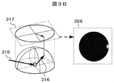
- FIG. 3A shows defect scattering of defects in which a tailing phenomenon occurs when the NA of the detection optical system is changed to 0.40, 0.75, 0.90, and 1.00 and the detection optical system of each NA is used.
- the example of the simulation result of the light distribution 386 and the dark field image 387 is shown.
- FIG. 3A is the result of a defect that tails in a direction along the laser incident direction 314.
- the scattered light distribution 386 of the defect is an intensity obtained by projecting the scattered light intensity distribution on the hemisphere of the light 316 scattered by the defect on the two-dimensional surface 317 parallel to the sample surface. Distribution is shown.
- the defect scattered light distributions 3861 to 3864 which are the results of the simulation of the defect scattered light distribution 386 shown in FIG. 3A, are displayed as relative values.
- the defect scattered light distributions 3861 to 3894 in each NA were imaged to obtain dark field images 3871 to 3874, respectively.
- the true defect center position is the intersection position of the arrows shown in the dark field images 3871 to 3874 from the four directions of up, down, left, and right.
- the defect is locally concentrated and scattered in a low-angle region in the forward scattering direction (an angle direction close to the normal direction of the surface of the sample 101).
- the defect that easily causes the tailing phenomenon tends to be concentrated and scattered in the local region. From the dark field image 387, it can be confirmed that the tailing phenomenon occurs in the defect of FIG. 3A when the dark field images 3872 and 3873, that is, NA 0.75 and 0.90.
- FIG. 4A shows an example of scattered light distribution (NA 1.00) of a tail defect that has a tail extending in a direction extending from the laser incident direction.
- the region 342 is a region where the scattered light intensity is extremely high, and the region 341 is a region where the scattered light intensity is low.
- a line 343 represents an incident surface of illumination.
- the illumination light incident surface is a surface perpendicular to the sample surface and parallel to the optical axis of the illumination light and including the optical axis of the illumination light in the surface.
- a circle 345 indicates an opening boundary of NA 0.90, and a circle 346 indicates an opening boundary of NA 0.40.
- the aperture boundary and the region where the intensity of the defect scattered light is strong overlap.
- (A) Anisotropy of diffracted light intensity at aperture boundary As shown in FIG. 4B, when the scattered light intensity region 342 overlaps with the opening boundary (the opening boundary 345 of NA 0.90 in FIG. 4B), the scattered light intensity is anisotropic at the opening boundary. Increases sex. In the region where the scattered light intensity is strong at the aperture boundary, the diffracted light intensity is higher than in other regions. In order to condense on the image plane, the direction in which the image spreads is an azimuth angle of strong scattered light intensity and an azimuth angle direction that is symmetric with respect to the azimuth angle.
- the image extends in the direction of the azimuth angle 347 of the extremely strong azimuth angle of the scattered light intensity and the azimuth angle of the optical axis.
- the intensity of the diffracted light of the scattered light at the aperture boundary is weak and the image spread is small compared to the azimuth angle 347.
- the dotted line 301 is the optical axis of the detection optical system
- 351 is the scatterer (foreign matter)
- arrow 359 is the strong scattered light
- arrow 360 is the weak scattered light
- line 354 is the pupil plane
- line 355 is the aperture boundary.
- the arrow 356 indicates strong diffracted light
- the arrow 357 indicates weak diffracted light
- the line 352 indicates the image plane
- the line 353 indicates the intensity of the dark field image.
- FIGS. 4D and 4E show the intensity change 360 of the scattered light on the line 343 passing through the optical axis 301 of the system.
- the horizontal axis 344 indicates the position on the illumination incident surface (line 343 in FIG. 4A)
- the vertical axis 361 indicates the scattered light intensity
- the region 346 indicates the detection optical system with NA of 0.40.
- the detection area is indicated by an area 345, which is the detection area of the detection optical system with NA of 0.90.
- a dotted line 362 in FIG. 4E indicates a change in the intensity of the opening boundary. As can be seen from FIG. 4 (e), the intensity change 362 at the opening boundary becomes significantly larger as the opening widens. The greater the intensity change, the more light spreads out of the aperture.
- a dark field image 371 of the target sample is acquired (Step 6011), the acquired dark field image 371 is binarized (Step 6012), and a luminance center of gravity 365 of the binarized dark field image 372 is derived (Step 6013).
- the luminance center of gravity 365 is output as defect coordinates (Step 6014).
- the means to suppress the tailing phenomenon will be described. From the tailing phenomenon occurrence mechanism described with reference to FIGS. 3 and 4, it can be seen that it is effective not to overlap the opening boundary with the extremely strong region of the defect scattered light as a method for suppressing the tailing phenomenon.
- a method of suppressing the tailing phenomenon there are [1] a method of reducing the NA of the detection optical system, or [2] a method of moderating the intensity change at the aperture boundary.
- a method for reducing the detection optical system NA a method using an objective lens having a small NA, or a method of arranging a spatial filter 401 (FIG. 6A) for limiting the aperture on the pupil plane of the detection optical system or in the vicinity thereof.
- a method for reducing the detection optical system NA a method using an objective lens having a small NA, or a method of arranging a spatial filter 401 (FIG. 6A) for limiting the aperture on the pupil plane of the detection optical system or in the vicinity thereof.
- the influence of the tailing phenomenon is small at NA 0.40, and the influence of the tailing phenomenon is large at NA 0.60.
- the NA required for aperture limitation is not limited thereto.
- an ND filter (a neutral density filter) having a transmittance distribution in which the transmittance gradually changes in the radial direction on the pupil plane or in the vicinity of the pupil plane of the detection optical system.
- the ND filter 402 is provided with a light shielding region 4022 around the central light transmission region 4021.
- the light shielding region 4022 has a spatial distribution in which the transmittance decreases from the center toward the outer periphery.
- the defect scattered light is blocked or reduced, and the defect detection sensitivity is lowered. Therefore, it is necessary to use the highest sensitivity detection and the detection that does not cause the tailing phenomenon. This reduces the inspection throughput.
- a filter having partial optical characteristics as a means for suppressing the decrease in defect scattered light as much as possible and suppressing the tailing phenomenon.
- a defect having a substantially isotropic shape and having a tail is shown in the dark field image 383 as shown in FIG. It has been found that there is a tendency to concentrate strongly in the vicinity of the front low angle region 342 and to scatter strongly. Therefore, in order to transmit light scattered on the sample as much as possible, there is a method of shielding or dimming only a minimum area.
- the light transmission region 4031 has a transmittance distribution in the radial direction in the front low angle region.
- the ND filter 404 FIG. 7B
- the region 4042 is arranged on the pupil plane of the detection optical system or in the vicinity of the pupil plane.
- the scattered light of the wafer is strongly scattered backward, it is also scattered in the front low-angle region. Therefore, in detecting a small defect of a size of a few tens of nanometers, even if the front low-angle region is shielded, the influence of sensitivity reduction is small. . Therefore, when the spatial filter 403 or 404 of FIG. 7A or 7B is used, the inspection can be performed without using the high sensitivity detection and the trailing phenomenon suppression detection separately. Moreover, you may use separately the filter for another further highly sensitive detection, and the detection using the filter which has a partial optical characteristic as shown to FIG. 7A or FIG. 7B.
- the first advantage is that the arrangement position of the linear polarizer does not need to be in the vicinity of the pupil plane, and can be arranged at an arbitrary position of the detection optical system.
- the second advantage is that detection using a polarizer suppresses scattered light from the wafer and has a high sensitivity for detecting minute defects, so that inspection can be performed without using high sensitivity detection and tailing phenomenon suppression detection. Moreover, you may use separately the further further highly sensitive detection and the detection using a linear polarizer.
- the tailing phenomenon is a phenomenon that occurs remarkably in laser oblique incidence illumination and a dark field light microscope having a high NA imaging detection optical system.
- a dark field light microscope with incident illumination a bright field light microscope with white or laser illumination, a phase contrast microscope, a dark field light microscope with a condensing detection optical system, an SEM, etc.
- no tailing phenomenon occurs. Therefore, as a means for suppressing the tailing phenomenon, white or laser light source ring illumination dark field light microscope, white oblique incidence illumination dark field light microscope, white or laser illumination bright field light microscope, phase contrast microscope, condensing detection optical system Means that do not cause a tailing phenomenon, such as dark field light microscopy or SEM, may be used.
- the dark field light microscope of white oblique incidence illumination has a wider illumination wavelength than that of a laser, so that the scattered light distribution is not extremely concentrated and widened, so that no tailing phenomenon occurs.
- FIG. 8A or 8B there is a filter as shown in FIG. 8A or 8B.
- the filter 411 shown in FIG. 8A transmits the forward scattered light component from the sample 101 through the transmission region 412 and blocks the other scattered light components and stray light with the light shielding unit 413.
- the S / N of the detection signal can be improved, and a smaller defect signal can be detected.
- the filter 421 shown in FIG. 8B transmits the forward scattered light component from the sample 101 through the transmission region 422 and the other scattered light components and stray light through the light shielding portions 423 to 425 where the transmittance gradually increases. It shields light. Even if such a filter is used, the S / N of the detection signal can be improved as in the case of the filter 411 in FIG. 8A, and a smaller defect signal can be detected.
- FIG. 8C shows a filter 431 in which the filter 404 shown in FIG. 7B and the filter 421 shown in FIG. 8B are combined.
- a filter By using such a filter, it is possible to simultaneously realize high-sensitivity detection and detection with the tailing phenomenon suppressed. The same effect can be obtained by combining the filter 403 shown in FIG. 7A and the filter 411 shown in FIG. 8A.
- the illumination light is emitted from the bright field light source 212, and the illumination light transmitted through the illumination lens 213 is emitted by the half mirror 214.
- Half of the light is reflected toward the objective lens 202 and is incident on the objective lens 202 to illuminate the surface of the sample 101 with bright field.
- the reflected light incident on the objective lens 202 is half of the light transmitted through the half mirror 214 and condensed by the lenses 203 and 204, and the image of the surface of the sample 101 by the imaging lens 206. Is imaged on the detection surface of the image sensor 207.
- a signal obtained by imaging the image of the surface of the sample 101 formed by the imaging device 207 is sent to the signal processing unit 221, and is displayed on the display screen 2221 of the image display unit 222 as an image of the surface of the sample 101. Is displayed.
- the operator observes the bright field image of the surface of the sample 101 displayed on the display screen 2221 and confirms that the image of the surface of the sample 101 is correctly formed on the imaging surface of the image sensor 207. .
- the height adjustment mechanism 209 of the objective lens is operated to pick up the image forming position of the image of the surface of the sample 101. It is correctly aligned on the imaging surface of the element 207.
- the stage 103 is rotated in the ⁇ direction to Adjust. This adjustment is performed before the start of the inspection, and after the adjustment is completed, the plurality of samples 101 are sequentially inspected as described in the pond.
- the illumination unit 201 irradiates the surface of the sample 101 with illumination light (dark field illumination).
- the control unit 224 controls the driving of the stage 103 that can move in the X and Y directions within the plane, and the sample 101 placed on the sample holder 102 is continuously moved in the X direction with a certain degree of independence.
- An image of scattered light that has been halved and passed through the lenses 203 and 204 and filtered by the filter 205 serving as a spatial distribution optical element is formed on the detection surface (not shown) of the imaging element 207 by the imaging lens 206. .
- a signal obtained by capturing an image of scattered light with the image sensor 207 is sent to the signal processing unit 221 and subjected to A / D conversion, and then a signal larger than the threshold is extracted as a defect by threshold processing.
- the optical conditions of the inspection can be switched by driving the filter folder 208 and replacing the filter 205 disposed on the optical axis 301 of the imaging optical system 210.
- the filter 205 can be replaced under a plurality of inspection conditions.
- the front surface of the sample 101 is inspected using a filter for suppressing the occurrence of the tailing phenomenon as the filter 205 in the first inspection for the sample 101, and then the high sensitivity detection is performed as the filter 205 in the second inspection.
- a filter for suppressing the occurrence of the tailing phenomenon as the filter 205 in the first inspection for the sample 101
- the high sensitivity detection is performed as the filter 205 in the second inspection.
- any one of the spatial filters 401 to 404 shown in any of FIGS. 6A to 7B is employed as a filter for suppressing the occurrence of the tailing phenomenon.
- the tailing phenomenon is suppressed in the scattered light image obtained by imaging with the imaging device 207.
- the difference between the defect coordinates obtained as the barycentric position of the luminance value distribution of the scattered light image captured by the image sensor 207 and the defect coordinates on the actual sample is reduced, and the position of the defect is detected from the detected image. Can be obtained with high accuracy.
- a filter for high sensitivity detection for example, as shown in FIG. 8A or FIG. 8B, an aperture is formed so as to cut back scattered light and side scattered light components that transmit forward scattered light components and easily become noise components.
- the filter 411 or 412 configured to limit the above is used.
- the forward scattered light incident on the portion 412 out of the scattered light generated from the sample 101 by the illumination light incident from the direction of the arrow 314 is transmitted and incident on the portion 413. It is configured to shield scattered light.
- the spatial filter 421 shown in FIG. 8B transmits forward scattered light incident on the portion 422 out of the scattered light generated from the sample 101 by the illumination light incident from the direction of the arrow 314, and passes through 424 from the portion 423.
- the light blocking ratio of the scattered light incident on the portion is gradually increased, and the scattered light incident on the portion 425 is completely shielded.
- the scattered light that has passed through the high-sensitivity detection filter as shown in FIG. 8A or 8B is imaged by the imaging lens 206, and the image is obtained from the image of the scattered light obtained by imaging with the imaging device 207.
- An area having a luminance equal to or higher than the threshold value is extracted as a defect, and the barycentric position of the luminance value distribution of the extracted defect image is obtained as the defect coordinate.
- the detected defect image and the position information of the defect are sent to and stored in the signal storage unit 223 and sent to the image display unit 222 to be displayed on the display screen 2221. Further, the detected defect image and the position information of the defect are transmitted to an upper processing apparatus via a communication line (not shown).
- the configuration in which the laser emitted from the light source 2011 by the illumination optical system unit 201 is condensed by the condenser lens 2012 and irradiated onto the sample 101 has been described.
- a cylindrical lens is applied to the condenser lens 2012.
- the sample 101 may be illuminated with light formed linearly.
- the filter 205 is switched and inspected twice has been described.
- the filter 205 is not switched and the front surface of the sample 101 is inspected once by using a filter for suppressing the occurrence of the tailing phenomenon. It may be a method to do.
- the present embodiment in detecting a minute defect on a sample by dark field illumination, it becomes possible to detect the defect image by reducing the occurrence of the tailing phenomenon, and detect the position of the defect with high accuracy. I was able to do it.
- the defect inspection apparatus 200 includes two sets of illumination optical systems. That is, as shown in FIG. 9, the defect inspection apparatus 200 according to this modification includes an optical microscope 1051, a signal processing unit 221, an image display unit 222, a signal storage unit 223, and a control unit 2241.
- the control unit 2241 is connected to an external data processing device by communication means (not shown).
- the optical microscope 1051 includes an illumination optical system unit 251 in addition to the illumination unit 201 described in the first embodiment. 9, the same reference numerals as those shown in FIG. 1 are the same as those described in the first embodiment, and thus the description thereof is omitted. Since the signal processing unit 221, the image display unit 222, and the signal storage unit 223 are the same as those described in the first embodiment, the description thereof is omitted.
- the plurality of filters 2051 held by the filter holder 2081 include a filter suitable when the illumination optical system unit 201 illuminates the sample 101, and an illumination optical system unit 251 when the sample 101 is illuminated.
- a suitable filter is included.
- the illumination optical system unit 251 is configured using a light source 2511 and a condensing lens 2512 for condensing and irradiating the light beam emitted from the light source 2511 onto the sample 101, as in the illumination optical system unit 201.
- the illumination unit 251 is arranged with respect to the sample 101 in the same azimuth direction as the illumination unit 101 and in different elevation directions, and illuminates the sample 101 with the same region as the region illuminated by the illumination unit 101.
- illumination optics A filter according to FIGS. 6A and 6B or FIGS. 7A and 7B corresponding to the system unit 251 is also provided.
- the control unit 2241 illuminates the sample 101 by sequentially switching between the illumination optical system unit 201 and the illumination optical system unit 251 at the time of inspection. That is, the control unit 2241 repeatedly drives the stage 103 to scan the sample 101 in the X direction or the Y direction, and the illumination by the illumination optical system unit 251 is stopped in the first scan.
- the illumination optical system unit 201 illuminates the sample 101 for inspection, and in the second scanning, the illumination optical system unit 251 illuminates the sample 101 with the illumination optical system unit 201 stopped, and the inspection is performed. .
- the control unit 2241 position information of a reference pattern (not shown) formed on the sample 101 obtained as a result of detecting the signal detected by the image sensor 207 in the first scan by the signal processing unit 221, and the second time Based on the position information of the reference pattern formed on the sample 101 obtained as a result of detecting the signal detected by the image sensor 207 in the scan by the signal processing unit 221, the signal detected by the image sensor 207 in the first scan is a signal.
- the result of processing by the processing unit 221 and the result of processing of the signal detected by the image sensor 207 in the second scan by the signal processing unit 221 are integrated, and classification is performed based on the detection of the defect and the image feature amount of the detected defect. I do.
- two-way illumination having the same azimuth angle and different elevation angles has been described.
- two-way illumination having the same elevation angle and different azimuth angles may be used, or a combination of them.
- Directional illumination may be used.
- a configuration may be adopted in which a polarizing filter is added to the illumination optical system units 201 and 251 to illuminate the sample 101 with polarized light.
- the illumination optical system unit 201 and the illumination optical system unit 251 are each provided with the light source 2011 or 2511, but only one of the light sources 2011 or 2511 is used to The light source may be shared by the illumination optical system unit 251.
- the following defect observation procedure is used. First, the entire surface of the sample is scanned by an inspection apparatus, a defect present on the sample is detected, and coordinates where the defect exists are acquired. Next, some or all of the defects detected by the inspection apparatus are observed in detail by the review apparatus based on the defect coordinates acquired by the inspection apparatus, and defect classification, cause analysis, and the like are performed.
- FIG. 10 shows an example of the configuration of the review apparatus 1000 in the present embodiment.
- the review apparatus 1000 according to the present embodiment can move the entire surface of the sample 101 under a scanning electron microscope 106 (hereinafter referred to as SEM) by moving the sample holder 102 carrying the sample 101 to be inspected and the sample holder 102.
- SEM scanning electron microscope
- Stage 103 SEM 106 for observing sample 101 in detail, optical height detection system 104 for detecting the height of the surface of sample 101 in order to focus the surface of sample 101 on the surface of sample 101, and optically detecting defects in sample 101
- An optical microscope 105 that detects and acquires detailed positional information of defects on the sample 101, a vacuum rod 112 that houses the SEM 106 and the objective lens of the optical microscope 105, the SEM 106, the optical height detection system 104, and the optical microscope 105 are controlled.
- Control system 125, user interface 123, library 122, inspection Network 121 that connects to the host system, such as device 107, is a storage device 124, in construction and save the external data and the like of the inspection apparatus 107 gives to the control system.
- the SEM 106 includes an electron beam source 1061, an extraction electrode 1062 that extracts and accelerates primary electrons emitted from the electron beam source in a beam shape, and a deflection that controls the trajectory of the primary electron beam extracted and accelerated by the extraction electrode.
- a secondary electron detector 1065 for detecting electrons, a reflected electron detector 1066 for detecting relatively high energy electrons such as reflected electrons generated from the sample 101 irradiated with the converged primary electron beam, and the like are provided. ing.
- the SEM 106 is disposed inside the vacuum chamber 112. A part of the optical microscope 1052 is also arranged inside the vacuum chamber 112.
- the configuration and function of the optical microscope 1052 are basically the same as those of the optical microscope 105 described in Embodiment 1 with reference to FIGS. 1 to 7B, but a part of the optical microscope 1052 in this embodiment is the same as that of the SEM 106. The difference is that it is arranged inside the vacuum chamber 112.
- the vacuum chamber 112 is provided with a glass window 1121 for introducing illumination light emitted from the illumination unit. Further, inside the vacuum chamber 112, there are a mirror 2013 for converting the optical path of the introduced illumination light into the direction of the sample 101, an objective lens 202 for condensing the scattered light from the sample 101, and an objective lens 202.
- a height control mechanism 209 for adjusting the position in the optical axis direction is arranged as a part of the optical microscope 1052, and the light condensed by the objective lens 202 is transmitted through the glass window 1122 provided in the vacuum chamber 112.
- the configuration leading to the half mirror 214 and the lenses 203 and 204 is different from the configuration of the optical microscope 105 in the first embodiment described with reference to FIG.
- the tailing phenomenon of the scattered light image described with reference to FIGS. 2 to 7B and the configuration of the filter corresponding thereto are also applied to this embodiment as they are.
- the control system 125 includes an SEM control unit 1251 that controls the SEM 106, an optical microscope control unit 1252 that controls the optical microscope (corresponding to the control unit 224 in the first embodiment shown in FIG. 1), and overall control that controls the entire review apparatus 1000.
- a portion 1256 is provided.
- the stage 103, the optical height detection system 104, the optical microscope 105, the SEM 106, the user interface 123, the library 122, and the storage device 124 are connected to the control system 125, and the control system 125 is connected upstream or upstream via the network 121. (For example, the inspection apparatus 107).
- the optical microscope 1052 reproduces a defect on the sample 101 detected by the inspection apparatus 107 that is a host system using the defect position information detected by the inspection apparatus 107.
- the optical height detection system 104 has a function of detecting (hereinafter referred to as detection), and the optical height detection system 104 serves as a focusing means for focusing the primary electron beam for focusing the primary electron beam of the SEM 106 on the surface of the sample 101.
- the control system 125 functions as a position correction unit that corrects position information of defects detected by inspection with another inspection apparatus 107 based on position information of defects detected by the optical microscope 1052.
- the SEM 106 has a function of observing a defect whose position information is corrected by the control system 125.
- the stage 103 places the sample 101 and moves between the optical microscope 1052 and the SEM 106 so that defects detected by the optical microscope 1052 can be observed by the SEM 106.
- FIG. 10 a general processing flow for observing defects detected by the inspection apparatus 107 (FIG. 10) with the review apparatus 1000 described with reference to FIG. 10 will be described with reference to FIG.
- a defect on the sample 101 is detected using the inspection apparatus 107 which is a higher-order or upstream system, and the other inspection apparatus 107 outputs inspection information of the sample 101 via the network 121 and stores it in the review apparatus 1000. Input to device 124.
- the inspection information of the sample 101 output by the other inspection device 107 is any one of defect coordinates, defect signal, defect shape, polarization of defect scattered light, defect type, defect label, defect feature amount, and scattering signal on the surface of the sample 101.
- the inspection result composed of a combination of these and the illumination incident angle, illumination wavelength, illumination azimuth angle, illumination intensity, illumination polarization, detector azimuth angle, detector elevation angle, detector detection angle of another inspection apparatus 107
- the inspection information obtained as a result of inspecting the sample 101 output for each detector or the inspection information of the sample 101 obtained by integrating a plurality of detector outputs is used. .
- the review device 1000 observes some or all of the defects extracted from the defects detected by the other inspection devices 107.
- rough alignment of the sample 101 is performed. This is performed by bright field observation with the optical microscope 105.
- the defect to be observed on the sample 101 using the position information of the defect previously detected by the other inspection apparatus 107 by the review apparatus 1000 is the field of view of the optical microscope 1052.
- the stage 103 is moved so as to enter (Step 6001).
- the objective lens 202 is moved by the height control mechanism 209 to perform focusing (Step 6002).
- Step 6003 an image is acquired by the image pickup device 207 of the optical microscope 1052 (Step 6003), the luminance value of the acquired image is quantized (Step 6004), a defect is searched for in the image (Step 6005), and the defect is detected. If it is (Step 6006-YES), defect coordinates are derived from the luminance distribution of the defect image (Step 6007), and if there is no need to detect other defects (Step 6008-No), the defect detection with the optical microscope 1502 is terminated. (Step 6009).
- this defect is detected using the position information of the defect detected in advance by the other inspection apparatus 107 based on the difference between the coordinates of the defect detected by the optical microscope 1052 and the position information of the defect previously detected by the other inspection apparatus 107.
- a deviation amount of the visual field position of the SEM 106 with respect to the defect when the observation with the SEM 106 is attempted is calculated.
- the position information of the defect detected in advance by the other inspection apparatus 107 is corrected, and the stage 103 is driven to move the defect whose position information is corrected to the field of view of the SEM 106, Observe with SEM106.
- the observed information is sent to the control system 125 and registered in the database 122. If there are a large number of defects to be observed, a representative number of them are extracted and obtained by detecting the position information of these extracted defects previously detected by another inspection apparatus 107 and the optical microscope 1052.
- the amount of deviation between the position of the defect detected in advance by another inspection apparatus 107 and the visual field position of the SEM 106 is obtained from the position information of each defect.
- the positional information obtained by detecting in advance by another inspection apparatus 107 is also corrected for defects that have not been detected by the optical microscope 1052 other than the representative several points, using the information on the obtained deviation amount.
- Step 6008-YES when other defect information is necessary (Step 6008-YES), the defect position information desired to be observed is acquired from the output result of the other inspection apparatus 107, and the procedure returns to the procedure for moving the defect to the optical microscope 1052 described above ( Step 6001), the process proceeds. If a defect cannot be detected by the above-described defect detection procedure (Step 6006-NO), it is considered that the defect is outside the field of view of the optical microscope 1052. Good.
- Step 6010-YES When searching for the peripheral portion (Step 6010-YES), the sample 101 is moved by an amount corresponding to the visual field (Step 6001), and processing is performed from the above-described defect detection procedure. Further, when the peripheral search is not performed (Step 6010 -NO), the process proceeds according to the procedure.
- the dark field light microscope 1052 in which the tailing phenomenon may occur is increased.
- An example of a processing flow in the case where the review apparatus 1000 detects a defect by using a sensitivity detection (hereinafter referred to as high sensitivity detection) means and a means in which the tailing phenomenon is suppressed is shown in FIGS. 13 to 15. Will be described.
- the defect on the sample 101 is detected using another inspection apparatus 107, and the other inspection apparatus 107 outputs the inspection information of the sample 101 via the network 121 and inputs it to the storage device 124 of the review apparatus 1000.
- the inspection information of the sample 101 output by the other inspection device 107 is any one of defect coordinates, defect signal, defect shape, polarization of defect scattered light, defect type, defect label, defect feature amount, and scattering signal on the surface of the sample 101.
- the inspection result composed of a combination of these and the illumination incident angle, illumination wavelength, illumination azimuth angle, illumination intensity, illumination polarization, detector azimuth angle, detector elevation angle, detector detection angle of another inspection apparatus 107 This is inspection information configured by inspection conditions configured by any one of the detection areas or a combination thereof.
- the inspection information obtained as a result of inspecting the sample 101 output for each detector or the inspection information of the sample 101 obtained by integrating a plurality of detector outputs is used. .
- FIG. 13 is an example of a processing flow in the case of imaging and inspecting all the detection target defects under a plurality of optical conditions including a high sensitivity detection condition and a tailing phenomenon suppression condition.
- the defect to be observed on the sample 101 is set to the high sensitivity condition using the position information of the defect previously detected by the other inspection apparatus 107 in the review apparatus 1000.
- the stage 103 is moved so as to enter the field of view of the dark field light microscope 1052 (Step 6001).
- the objective lens 202 is moved by the height control mechanism 209 to perform focusing, an image acquired by the imaging device 207 of the dark field light microscope 1052 set to the high sensitivity condition is acquired (Step 6016), and the acquired image is acquired. If a defect is detected and a defect is detected (Step 6017—YES), defect coordinates are derived from the luminance distribution of the defect image.
- Step 6018-YES when other defect information is necessary (Step 6018-YES), the defect position information to be observed is acquired from the output result of the other inspection apparatus 107, and the above-mentioned Returning to the procedure for moving the defect to the dark field light microscope 1052 set to the high sensitivity condition (Step 6015), the process proceeds. If the defect cannot be detected by the above-described defect detection procedure (Step 6017-NO), it is considered that the defect is outside the visual field of the dark field light microscope 1052 set to the high sensitivity condition. The peripheral portion of the visual field of the dark field light microscope 1052 may be searched.
- Step 6024-YES When searching for the peripheral part (Step 6024-YES), the sample 101 is moved by an amount corresponding to the visual field (Step 6025), and processing is performed from the above-described defect detection procedure. Further, when the peripheral search is not performed (Step 6024 -NO), the process proceeds according to the procedure. Next, if it is not necessary to detect other defects in the dark field light microscope 105 set to the high sensitivity condition (Step 6018-NO), the dark field light microscope 1052 set to the optical condition in which the tailing phenomenon is suppressed is displayed. In order to enter, the stage 103 is moved using the position information of the defect detected by the other inspection apparatus 107 (Step 6019).
- the height control mechanism 209 moves the objective lens 202 to perform focusing, and the dark field optical microscope 1052 is imaged by the image sensor 207 in an optical condition in which the tailing phenomenon is suppressed.
- Step 6020 if a defect is searched for in the acquired image and a defect is detected (Step 6021-YES), defect coordinates are derived from the luminance distribution of the defect image. If it is not necessary to detect another defect (Step 6022-No), the defect detection in the dark field light microscope 1052 is terminated (Step 6023).
- Step 6022-YES the defect to be observed from the output result of the other inspection apparatus 107
- the position information is acquired, and the process returns to the above-described procedure for moving the defect to the dark field light microscope 1052 (Step 6019), and the process proceeds.
- Step 6021-NO If the defect cannot be detected by the above-described defect detection procedure (Step 6021-NO), it is considered that the defect is outside the field of view of the dark field light microscope 1052. May be.
- Step 6026-YES When searching for the peripheral portion (Step 6026-YES), the sample 101 is moved by an amount corresponding to the visual field (Step 6027), and processing is performed from the above-described defect detection procedure. Further, when the peripheral search is not performed (Step 6026 -NO), the process proceeds according to the procedure.
- the defect coordinates obtained in the state where the dark field light microscope 1052 is set to the high sensitivity condition or the optical condition in which the tailing phenomenon is suppressed Based on the difference between the defect coordinates obtained in the state where the dark field light microscope 1052 is set to the high sensitivity condition or the optical condition in which the tailing phenomenon is suppressed, and the position information of the defect detected in advance by another inspection apparatus 107, Using the positional information of the defect detected by the other inspection apparatus 107, a deviation amount of the visual field position of the SEM 106 with respect to the defect when this defect is to be observed with the SEM 106 is calculated. Based on the calculated deviation amount, the position information of the defect detected in advance by the other inspection apparatus 107 is corrected, and the defect whose position information is corrected is moved to the field of view of the SEM 106 for observation. At this time, the observed information is sent to the control system 125 and registered in the database 122.
- the position information detected by the other inspection apparatus 107 in advance and the light defects are used to detect the extracted defects.
- the amount of deviation between the position of the defect detected in advance by another inspection apparatus 107 and the visual field position of the SEM 106 is obtained from the position information of the defect.
- the positional information obtained by detecting in advance by another inspection apparatus 107 is also corrected for defects that have not been detected by a light microscope other than a representative number of points.
- tail coordinates suppression means derived defect coordinates Acquisition of defect coordinates derived from acquired images of dark field light microscope 1052 set to high sensitivity conditions (hereinafter referred to as high sensitivity means derived defect coordinates) and dark field light microscope 1052 set to optical conditions in which the tailing phenomenon is suppressed Either of the defect coordinates derived from the image (hereinafter referred to as tail coordinates suppression means derived defect coordinates) may be used.
- the defect coordinates derived from the tailing suppression means are used.
- the defect coordinates derived from the high-sensitivity means are used.
- the method used, or the presence or absence of the tailing phenomenon is determined from the difference between the defect coordinates derived from the high sensitivity means derived defect coordinates and the tailing suppression means derived defect coordinates.
- a defect detected only from an image picked up with either a dark field light microscope under high sensitivity conditions or an optical microscope under optical conditions with suppressed tailing phenomenon is detected using the picked-up image under the detected conditions. Use coordinates.
- the defect to be observed on the sample 101 is suppressed from the tailing phenomenon by using the position information of the defect previously detected by the other inspection apparatus 107 in the review apparatus 1000 based on the defect coordinates acquired by the other inspection apparatus 107.
- the stage 103 is moved so as to enter the field of view of the dark field light microscope 1052 set to the optical condition set (Step 6028).
- the objective lens 202 is moved by the height control mechanism 209 to perform focusing, and an image captured by the dark field light microscope 1052 set to the optical condition in which the tailing phenomenon is suppressed is acquired (Step 6029). If a defect is searched for in the acquired image and a defect is detected (Step 6030—YES), defect coordinates are derived from the luminance distribution of the defect image.
- Step 6031-NO If it is not necessary to detect other defects in the dark field light microscope 1052 set to the optical condition in which the tailing phenomenon is suppressed (Step 6031-NO), the dark field light microscope 1052 set to the optical condition in which the tailing phenomenon is suppressed. Since the defect is detected in (Step 6032-YES), it is not necessary to detect the defect with the dark field light microscope 1052 set to the high sensitivity condition (Step 6036-No), and the defect detection is finished (Step 6037).
- Step 6031-YES when other defect information is required in the dark field light microscope 1052 set to the optical condition in which the tailing phenomenon is suppressed (Step 6031-YES), the defect position information to be observed from the output result of the other inspection apparatus 107 And the process returns to the procedure for moving the defect to the dark field light microscope 1052 set to the optical condition in which the above-described tailing phenomenon is suppressed (Step 6028), and the process proceeds.
- a defect cannot be detected by the above-described defect detection procedure (Step 6030-NO)
- it is considered that the defect is outside the visual field of the dark field light microscope 1052 set to the optical condition in which the tailing phenomenon is suppressed.
- the peripheral portion of the visual field of the dark field light microscope 1052 may be searched.
- Step 6038-YES When searching for the peripheral part (Step 6038-YES), the sample 101 is moved by an amount corresponding to the visual field (Step 6039), and processing is performed from the above-described defect detection procedure. Further, when the vicinity search is not performed (Step 6038 -NO), the process proceeds according to the procedure.
- the defect could not be detected by the dark field light microscope 1052 set to the optical condition in which the tailing phenomenon was suppressed (Step 6030-NO), and the defect could not be detected even if the periphery was searched and imaged, and the periphery search was terminated.
- Step 3038-NO defect detection is impossible with the dark field light microscope 1052 set to the optical condition in which the tailing phenomenon is suppressed (Step 6032-NO), and defect detection is performed with the dark field light microscope 1052 set to the high sensitivity condition.
- the defect to be observed on the sample 101 is set to the high sensitivity condition using the position information of the defect previously detected by the other inspection apparatus 107 by the review apparatus 100 based on the defect coordinates acquired by the other inspection apparatus 107.
- the stage 103 is moved so as to fall within the field of view of the dark field light microscope 1052 (Step 6033).
- Step 6034 an image is acquired by imaging with the dark field light microscope 1052 set to the high sensitivity condition (Step 6034). If a defect is searched for in the acquired image and a defect is detected (Step 6035-YES), the defect image is acquired. Defect coordinates are derived from the luminance distribution. Next, when other defect information is necessary in the dark field light microscope 1052 set to the high sensitivity condition (Step 6036-YES), the defect position information to be observed is acquired from the output result of the other inspection apparatus 107, and the above-mentioned Returning to the procedure for moving the defect to the dark field light microscope 1052 (Step 6032), the process proceeds.
- Step 6035-NO If the defect cannot be detected by the above-described defect detection procedure (Step 6035-NO), it is considered that the defect is outside the field of view of the dark field light microscope 1052. May be.
- the sample 101 is moved by an amount corresponding to the visual field (Step 6041), and processing is performed from the above-described defect detection procedure. Further, when the peripheral search is not performed (Step 6040-NO), the process proceeds according to the procedure. Then, the defect coordinates obtained by using the dark field light microscope 1052 set to the optical condition in which the tailing phenomenon is suppressed or the dark field light microscope 1052 set to the high sensitivity condition and the position of the defect detected in advance by another inspection apparatus 107 are used. A deviation amount of the visual field position of the SEM 106 with respect to the defect when the defect is to be observed with the SEM 106 is calculated using the position information of the defect detected by the other inspection apparatus 107 in advance from the difference from the information.
- the position information of the defect detected in advance by the other inspection apparatus 107 is corrected, and the defect whose position information is corrected is moved to the field of view of the SEM 106 and observed. At this time, the observed information is sent to the control system 125 and registered in the database 122.
- the positional information of the extracted defects detected in advance by another inspection apparatus 107 and the tailing phenomenon are suppressed. From the position information of each defect detected by the dark field light microscope 1052 set to the optical condition or the dark field light microscope 1052 set to the high sensitivity condition, the position of the defect detected in advance by another inspection apparatus 107 and the SEM 106 The amount of deviation of the visual field position is obtained.
- the output information of the other inspection apparatus 107 is used, an inspection unit is selected for each defect to be detected, and a processing flow when imaging / inspection is performed using the selected inspection unit will be described with reference to FIG. I will explain.
- the light microscope detection condition of the defect to be detected is determined (Step 6043).
- defect coordinates, wafer information, defect brightness, defect size, defect class information, or feature values based on them are used.
- a defect having a brightness higher than the threshold is detected by setting the dark field light microscope 1052 to an optical condition in which the tailing phenomenon is suppressed.
- the defect is detected by setting the optical condition of the dark field light microscope 1052 to a high sensitivity condition.
- a defect with a large sensor output in the front and low angle regions is detected by setting the dark field light microscope 1052 to an optical condition in which the tailing phenomenon is suppressed.
- the defect is detected by the detection method determined in Step 6043.
- a defect to be detected in a state where the optical condition of the dark field light microscope 1052 is set to an optical condition in which the tailing phenomenon is suppressed (Step 6044-YES) is determined in advance by the review apparatus 1000 based on the defect coordinates acquired by the other inspection apparatus 107.
- the stage 103 is moved so that the defect to be observed on the sample 101 enters the visual field of the optical microscope using the position information of the defect detected by the other inspection apparatus 107 (Step 6045).
- the objective lens 202 is moved by the height control mechanism 209 to perform focusing, an image captured by the imaging device 207 of the dark field light microscope 1052 is acquired (Step 6046), and a defect is searched for in the acquired image. If a defect is detected (Step 6047-YES), defect coordinates are derived from the luminance distribution of the defect image.
- Step 6048-YES when other defect information is necessary (Step 6048-YES), the defect position information to be observed is output from the output result of the other inspection apparatus 107.
- the process returns to the procedure for obtaining and determining the optical microscope inspection condition for the defect described above (Step 6044), and the process proceeds. If the defect cannot be detected by the above-described defect detection procedure (Step 6047-NO), it is considered that the defect is outside the field of view of the dark field light microscope 1052, and thus the periphery of the field of view of the dark field light microscope 1052 is searched. May be.
- Step 6055-YES When searching for the peripheral portion (Step 6055-YES), the sample 101 is moved by an amount corresponding to the visual field (Step 6056), and processing is performed from the above-described defect detection procedure. Further, when the peripheral search is not performed (Step 6055 -NO), the process proceeds according to the procedure.
- the detection method determined in Step 6043 is the darkness set to the high sensitivity condition.
- the position information of the defect detected by the other inspection apparatus 107 is used so that the defect enters the field of view of the dark field light microscope 1052 set to the high sensitivity condition.
- the stage 103 is moved (Step 6050).
- the objective lens 202 is moved by the height control mechanism 209 to perform focusing, and an image is acquired by the imaging device 207 of the dark field light microscope 1052 set to the high sensitivity condition (Step 6051). If a defect is searched for in the acquired image and a defect is detected (Step 6052-YES), defect coordinates are derived from the luminance distribution of the defect image. If it is not necessary to detect another defect (Step 6053-NO), the defect detection in the dark field light microscope 1052 is terminated (Step 6054).
- Step 6050 the process returns to the above-described procedure for moving the defect to the dark field light microscope 105 (Step 6050), and the process is performed. Proceed.
- Step 6052-NO If a defect cannot be detected by the above-described defect detection procedure (Step 6052-NO), it is considered that the defect is outside the field of view of the optical microscope 105. Good.
- Step 6058-YES When searching for the peripheral part (Step 6058-YES), the sample 101 is moved by an amount corresponding to the visual field (Step 6059), and the process is performed from the above-described defect detection procedure. Further, when the vicinity search is not performed (Step 6058 -NO), the process proceeds according to the procedure.
- the defect coordinates obtained by using the dark field light microscope 1052 set to the optical condition in which the tailing phenomenon is suppressed or the dark field light microscope 1052 set to the high sensitivity condition and the position of the defect detected in advance by another inspection apparatus 107 are used.
- a deviation amount of the visual field position of the SEM 106 with respect to the defect when the defect is to be observed with the SEM 106 is calculated using the position information of the defect detected by the other inspection apparatus 107 in advance from the difference from the information. Based on the calculated deviation amount, the position information of the defect detected in advance by the other inspection apparatus 107 is corrected, and the defect whose position information is corrected is moved to the field of view of the SEM 106 for observation.
- the observed information is sent to the control system 125 and registered in the database 122.
- representative representative points are extracted, and the positional information detected by the other inspection apparatus 107 in advance and the tailing phenomenon of the extracted defects are suppressed.
- the amount of deviation between the position of the defect detected in advance by the other inspection apparatus 107 and the visual field position of the SEM 106 is obtained from the position information of each defect obtained by detection with a condition light microscope or a dark field light microscope under high sensitivity conditions.
- the position information obtained by detecting in advance by the other inspection apparatus 107 is also corrected for defects that are not detected by the dark field light microscope 1052 other than the representative few points. Further, in the light microscope inspection condition determined in Step 6043, a defect (Step 6052-NO) that is not detected by the dark field light microscope 1052 set to the high sensitivity condition is detected in the dark field light microscope 1052 set to the high sensitivity condition.
- the dark field light microscope 1052 may be detected by setting the optical condition in which the tailing phenomenon is suppressed (not shown).
- the method of switching between the high sensitivity detection condition and the detection of the optical condition that suppresses the tailing phenomenon moves the filter holder 208 (FIG. 11) and replaces the filter 205 on the optical axis.
- a rotary revolver type filter holder may be used instead of a slide type like the filter holder 208.
- the filter 205 (FIG. 11) may use one or more of the filters and polarizers described in FIG. 6A or 6B or FIG. 7A or 7B in the first embodiment. Good.
- MEMS or liquid crystal is used for the filter 205, there is a method of switching by changing the optical characteristics by an applied voltage instead of switching by the filter holder 208.
- the high-sensitivity means and the tailing phenomenon suppression means may or may not be used properly.
- a method of determining whether or not a tailing phenomenon has occurred in the dark field image acquired by the dark field light microscope 1052 (FIG. 11)
- a method of determining from the shape of the defect dark field image acquired by the dark field light microscope 1052 Alternatively, there is a method of comparing and determining a plurality of dark field images acquired under different optical conditions using the dark field light microscope 1052.
- a defect in which the tailing phenomenon occurs is referred to as a tailing defect
- a defect in which the tailing phenomenon does not occur is referred to as a non-tailing defect.
- a method for determining whether or not the defect is a tail defect from the defect dark field image acquired by the dark field light microscope 1052 there is a method using a feature amount obtained from the shape of the defect dark field image. For example, the tilt angle of the defect dark field image, the size of the defect dark field image in the field of the dark field light microscope 1052, or the ratio to the area, the ratio of the major axis to the minor axis of the defect dark field image, or a combination thereof
- a defect whose feature value obtained from the shape of the defect dark field image satisfies a set value is determined as a tail defect, and the other is determined as a non-tail defect.
- the advantage of this method is that the time required for defect detection is short because it is not necessary to acquire a defect dark field image under a plurality of conditions.
- the different optical conditions include, for example, the illumination intensity, the image sensor 207 There is an image acquisition accumulation time, an incident azimuth angle of illumination with respect to defects, and the like.
- a method of changing the incident azimuth angle of illumination there are a method of rotating the wafer, or a method of switching the incident azimuth angle of the laser emitted from the illumination unit 201 to the wafer.
- the tailing direction changes by ⁇ / 2 depending on the incident azimuth angle of the laser.
- the change in the shape of the defect dark field image becomes anisotropic (the tail becomes shorter) in the tail defect.
- the shape of the defect dark field image changes almost isotropically.
- the stage 103 is moved so that the defect to be observed on the sample 101 enters the visual field of the dark field light microscope 105 using the position information of the defect previously detected by the other inspection apparatus 107 in the review apparatus 1000 (Step 6060).
- the objective lens 202 is moved by the height control mechanism 209 to perform focusing, and the dark field optical microscope 105 captures an image to acquire an image (Step 6061), searches for the defect in the acquired image, and detects the defect. If so (step 6017-YES), it is next determined from the image acquired in step 6061 whether or not it is a tail defect.
- the defect coordinates are derived from the luminance distribution of the defect image using the algorithm A for the tail defect (Step 6064).
- the defect coordinates are derived from the brightness distribution of the defect image using the algorithm B for non-tailing defect.
- algorithm A there is a method in which an acquired image is quantized with a luminance value, and an end opposite to the tail (left end in the case of the dark field image 384 in FIG. 2B) is used as a defect coordinate.
- algorithm B there is a method in which an acquired image is quantized with a luminance value, and the luminance center of gravity is used as a defect coordinate.
- a method for determining whether the detected defect is a tailing defect or a non-tailing defect there is a method using a feature value obtained from the shape of the defect darkfield image acquired by the darkfield optical microscope 1052. For example, the tilt angle of the defect dark field image, the size of the defect dark field image in the field of the dark field light microscope 1052, or the ratio to the area, the ratio of the major axis to the minor axis of the defect dark field image, or a combination thereof
- a defect whose feature value obtained from the shape of the defect dark field image satisfies a set value is determined as a tail defect, and the other is determined as a non-tail defect.
- the tail extends in a direction parallel to the incident surface of the illumination, so the tilt angle of the defect dark field image is near the incident azimuth angle of the illumination.
- the defect it may be determined that the defect is a tailing defect.
- Step 6065-YES when other defect information is required in the dark field light microscope 105 (Step 6065-YES), the defect position information to be observed is acquired from the output result of the other inspection apparatus 107, and the above-described high sensitivity condition is set. Returning to the procedure for moving the defect to the dark field light microscope 105 (Step 6060), the process proceeds.
- Step 6062-NO If the defect cannot be detected by the above-described defect detection procedure (Step 6062-NO), it is considered that the defect is outside the field of view of the dark field light microscope 105. Therefore, the periphery of the field of view of the dark field light microscope 105 is searched. May be.
- the sample 101 is moved by an amount corresponding to the visual field (Step 6068), and processing is performed from the above-described defect detection procedure. Further, when the peripheral search is not performed (Step 6067 -NO), the process proceeds according to the procedure.
- Step 6065-NO the defect detection with the light microscope is terminated (Step 6066).
- a defect on the sample 101 is detected using another inspection apparatus 107, and the inspection apparatus 107 outputs inspection information of the sample 101 via the network 121 and inputs it to the storage device 124 of the review apparatus 100.
- the inspection information of the sample 101 output by the other inspection device 107 is any one of defect coordinates, defect signal, defect shape, polarization of defect scattered light, defect type, defect label, defect feature amount, and scattering signal on the surface of the sample 101.
- the inspection result composed of a combination of these and the illumination incident angle, illumination wavelength, illumination azimuth angle, illumination intensity, illumination polarization, detector azimuth angle, detector elevation angle, detector detection angle of another inspection apparatus 107
- the inspection information obtained as a result of inspecting the sample 101 output for each detector or the inspection information of the sample 101 obtained by integrating a plurality of detector outputs is used.
- the review device 1000 observes some or all of the defects extracted from the defects detected by the other inspection devices 107.
- rough alignment of the sample 101 is performed (Step 6078). This is performed by bright field observation provided in the dark field light microscope 1052.
- the stage 103 is moved so that the defect to be observed on the sample 101 enters the visual field of the dark field light microscope 1052 using the position information of the defect detected in advance by the other inspection apparatus 107 in the review apparatus 1000 (Step 6079).
- the objective lens 202 is moved by the height control mechanism 209 to perform focusing (Step 6080).
- a defect is searched from the image obtained by imaging with the dark field light microscope 1052 (Step 6081), and if a defect is detected (Step 6082-YES), the defect detection position by the optical microscope 105 and another defect inspection apparatus in advance.
- the amount of deviation of the visual field position of the SEM 106 with respect to the defect when the defect is to be observed with the SEM 106 using the position information of the defect detected in advance by another inspection apparatus 107 from the difference from the position information of the defect detected by Calculate (Step 6083).
- the position information of the defect detected in advance by the other inspection apparatus 107 is corrected (Step 6084), and the defect whose position information is corrected is moved to the field of view of the SEM 106 for observation. (Step 6086).
- the observed information is sent to the control system 125 and registered in the database 122.
- Step 6090 the position information obtained in advance by another inspection apparatus 107 is corrected.
- a defect on the sample 101 is detected using another inspection apparatus 107, and the other inspection apparatus 107 outputs inspection information of the sample 101 via the network 121 and inputs it to the storage device 124 of the review apparatus 1000.
- the inspection information of the sample 101 output by the other inspection device 107 is any one of defect coordinates, defect signal, defect shape, polarization of defect scattered light, defect type, defect label, defect feature amount, and scattering signal on the surface of the sample 101.
- the inspection result composed of a combination of these and the illumination incident angle, illumination wavelength, illumination azimuth angle, illumination intensity, illumination polarization, detector azimuth angle, detector elevation angle, detector detection angle of another inspection apparatus 107
- the inspection information obtained as a result of inspecting the sample 101 output for each detector or the inspection information of the sample 101 obtained by integrating a plurality of detector outputs is used.
- the review device 1000 observes some or all of the defects extracted from the defects detected by the other inspection devices 107.
- rough alignment of the sample 101 is performed (Step 6078). This is performed by bright field observation using the dark field light microscope 1052.
- the stage 103 is moved so that the defect to be observed on the sample 101 enters the visual field of the dark field light microscope 1052 using the position information of the defect detected in advance by the other inspection apparatus 107 in the review apparatus 1000 (Step 6079).
- the objective lens 202 is moved by the height control mechanism 209 to perform focusing (Step 6080).
- the defect is searched from the image acquired by imaging with the dark field light microscope 1052 (Step 6081), and if the defect is detected (Step 6082-YES), the defect detection position by the dark field light microscope 1052 and other inspection apparatuses are previously detected.
- the amount of deviation of the visual field position of the SEM 106 with respect to the defect when attempting to observe this defect with the SEM 106 using the position information of the defect previously detected by another inspection apparatus 107 from the difference from the position information of the defect detected by the 107 Is calculated (Step 6083).
- the position information of the defect detected in advance by the other inspection apparatus 107 is corrected (Step 6084), and the defect whose position information is corrected is moved to the field of view of the SEM 106 for observation. (Step 6086).
- the observed information is sent to the control system 125 and registered in the database 122.
- Step 6090 the position information obtained in advance by another inspection apparatus 107 is corrected.
- Step 6091-NO If the defect cannot be detected by the SEM 106 (Step 6091-NO) and the periphery is searched by the SEM 106 (Step 6092-YES), the field of view of the SEM is moved, or the sample 101 is moved to search the periphery (Step 6093). To proceed.
- Step 6091-NO If the defect cannot be detected by the SEM 106 (Step 6091-NO), the periphery is not searched (Step 6092-NO), and other defect coordinate candidates are observed (Step 6094-YES), optical conditions different from those used in Step 6081
- the defect is detected again with (Step 6095-YES) or is not detected again with the dark field light microscope 1052 (Step 6095-NO), and the image acquired in Step 6081 is used and there is a defect different from the coordinates moved in Step 6085.
- the field of view of the SEM or the sample is moved to the defect coordinates that are highly likely to be performed (Step 6093), and the process proceeds.
- Defect coordinates that have a high possibility of having a defect other than the coordinates moved in Step 6085 are shorter in the accumulation time of the image sensor than the image used for defect coordinate derivation in Step 6083, and the amount of coordinate deviation due to tailing is, for example, This is derived by a method using a small number of images or a method for deriving defect coordinates using an algorithm different from the algorithm used for defect coordinate derivation in Step 6083.
- the stage 103 is moved so that the defect to be observed on the sample 101 enters the visual field of the dark field light microscope 1052 using the position information of the defect detected in advance by the other inspection apparatus 107 in the review apparatus 1000 (Step 6096).
- the objective lens 202 is moved by the height control mechanism 209 to perform focusing, and an image is acquired by imaging with the dark field light microscope 1052 (Step 6097).
- a defect is searched for in the acquired image, and the defect is detected. If so (Step 6098-YES), it is next determined from the image acquired in Step 6097 whether or not the defect is a tailing defect. If the target defect is a tailing defect (Step 6099-YES), the optical field of the dark field light microscope 1052 is determined.
- the condition is changed to an optical condition that is less affected by the tailing phenomenon (Step 6100), the image is acquired by capturing with the dark field light microscope 1052 (Step 6101), the defect is searched for in the acquired image, and the defect is detected. If this is the case (Step 6102-YES), defect coordinates are derived from the image acquired in Step 6101 (Step 6103). If the target defect is a non-tailing defect (Step 6099-NO), defect coordinates are derived from the image acquired in Step 6097 (Step 6103).
- Step 6104-YES when other defect information is necessary in the dark field light microscope 1052 (Step 6104-YES), the defect position information to be observed is acquired from the output result of the other inspection apparatus 107, and the above-described high sensitivity condition is set. Returning to the procedure for moving the defect to the dark field light microscope 1052 (Step 6096), the process proceeds.
- Step 6098-NO If the defect cannot be detected from the image acquired in Step 6097 (Step 6098-NO), it is considered that the defect is outside the field of view of the dark field light microscope 1052. May be.
- the sample 101 is moved by an amount corresponding to the visual field (Step 6107), and the processing is performed from the defect detection procedure described above. If no peripheral search is performed (Step 6106-NO), the process proceeds according to the procedure.
- Step 6102-NO If the defect cannot be detected from the image acquired in Step 6101 (Step 6102-NO), it is considered that the defect is outside the visual field of the dark field light microscope 1052. May be.
- Step 6108—YES the sample 101 is moved by an amount corresponding to the visual field (Step 6109), and processing is performed from the above-described defect detection procedure. If the peripheral search is not performed (Step 6108 -NO), the process proceeds according to the procedure.
- Step 6104-NO the defect detection with the dark field light microscope 1052 is terminated (Step 6105).
- the optical condition to be changed in Step 6101 is one of the illumination light quantity, the illumination incident angle, the illumination azimuth angle, the accumulation time at the time of image acquisition, the optical characteristics of the filter 205, or a combination thereof. is there. If the accumulation time of the image sensor 207 is shortened or the amount of illumination light is reduced, the tail length of the tail defect is shortened, and the influence of the tailing phenomenon is reduced.
- the illumination intensity there are a control of a voltage applied to the illumination optical system 201, an ND filter disposed on the optical axis of the detection optical system, and an optical path switching for changing the incident angle of illumination. Also, if the incident angle of illumination and the azimuth angle of illumination are changed, the distribution of defect scattered light changes, so the area where the defect scattered light is concentrated locally and the intensity is strong, and the aperture boundary of the detection optical system does not overlap. When the direction is selected, the influence of the tailing phenomenon can be suppressed.
- Filters 205 used under optical conditions that are less affected by the tailing phenomenon include a ND filter for dimming, a spatial filter for limiting the aperture as shown in FIGS. 8A and 8B, FIGS. 6A, 6B, and 7A. And the filter described in FIG. 7B.
Landscapes
- Physics & Mathematics (AREA)
- Health & Medical Sciences (AREA)
- Life Sciences & Earth Sciences (AREA)
- Chemical & Material Sciences (AREA)
- Analytical Chemistry (AREA)
- Biochemistry (AREA)
- General Health & Medical Sciences (AREA)
- General Physics & Mathematics (AREA)
- Immunology (AREA)
- Pathology (AREA)
- Investigating Materials By The Use Of Optical Means Adapted For Particular Applications (AREA)
- Length Measuring Devices By Optical Means (AREA)
Abstract
Priority Applications (2)
| Application Number | Priority Date | Filing Date | Title |
|---|---|---|---|
| KR1020157010239A KR101729952B1 (ko) | 2012-11-08 | 2013-11-05 | 결함 검출 방법 및 그 장치 및 결함 관찰 방법 및 그 장치 |
| US14/441,742 US9683946B2 (en) | 2012-11-08 | 2013-11-05 | Method and device for detecting defects and method and device for observing defects |
Applications Claiming Priority (2)
| Application Number | Priority Date | Filing Date | Title |
|---|---|---|---|
| JP2012246035A JP5946751B2 (ja) | 2012-11-08 | 2012-11-08 | 欠陥検出方法及びその装置並びに欠陥観察方法及びその装置 |
| JP2012-246035 | 2012-11-08 |
Publications (1)
| Publication Number | Publication Date |
|---|---|
| WO2014073532A1 true WO2014073532A1 (fr) | 2014-05-15 |
Family
ID=50684635
Family Applications (1)
| Application Number | Title | Priority Date | Filing Date |
|---|---|---|---|
| PCT/JP2013/079902 WO2014073532A1 (fr) | 2012-11-08 | 2013-11-05 | Procédé et dispositif de détection de défauts, et procédé et dispositif d'observation de défauts |
Country Status (5)
| Country | Link |
|---|---|
| US (1) | US9683946B2 (fr) |
| JP (1) | JP5946751B2 (fr) |
| KR (1) | KR101729952B1 (fr) |
| TW (1) | TWI480542B (fr) |
| WO (1) | WO2014073532A1 (fr) |
Families Citing this family (11)
| Publication number | Priority date | Publication date | Assignee | Title |
|---|---|---|---|---|
| EP2896061B1 (fr) * | 2012-09-14 | 2023-06-28 | Delmic Ip B.V. | Appareil d'inspection de particules chargées et optique intégrée |
| JP6222935B2 (ja) * | 2013-02-14 | 2017-11-01 | キヤノン株式会社 | 画像形成装置 |
| JP2015206642A (ja) * | 2014-04-18 | 2015-11-19 | 株式会社日立ハイテクノロジーズ | 欠陥観察方法及びその装置 |
| JP6424143B2 (ja) * | 2015-04-17 | 2018-11-14 | 株式会社ニューフレアテクノロジー | 検査方法およびテンプレート |
| JP6635712B2 (ja) * | 2015-08-21 | 2020-01-29 | キヤノン株式会社 | 検査方法、検査装置、画像処理装置、プログラム及び記録媒体 |
| JP2017067633A (ja) * | 2015-09-30 | 2017-04-06 | キヤノン株式会社 | 検査装置および物品製造方法 |
| JP6594223B2 (ja) * | 2016-02-22 | 2019-10-23 | 富士フイルム株式会社 | 位相差顕微鏡および撮像方法 |
| JP6688184B2 (ja) * | 2016-07-20 | 2020-04-28 | 東レエンジニアリング株式会社 | ワイドギャップ半導体基板の欠陥検査装置 |
| TWI751233B (zh) * | 2016-11-28 | 2022-01-01 | 美商克萊譚克公司 | 用於從低解析度檢測影像重建高解析度點擴散函數之系統及方法 |
| US11158040B2 (en) * | 2018-06-29 | 2021-10-26 | Taiwan Semiconductor Manufacturing Co., Ltd. | Method for identifying robot arm responsible for wafer scratch |
| CN112104968B (zh) * | 2020-09-15 | 2021-10-15 | 沈阳风驰软件股份有限公司 | 一种无线耳机外观缺陷检测系统及检测方法 |
Citations (8)
| Publication number | Priority date | Publication date | Assignee | Title |
|---|---|---|---|---|
| JPH0254494B2 (fr) * | 1979-11-06 | 1990-11-21 | Tokyo Shibaura Electric Co | |
| JPH0943160A (ja) * | 1995-07-31 | 1997-02-14 | Toray Ind Inc | 光学測定装置 |
| JP2001133417A (ja) * | 1999-06-15 | 2001-05-18 | Applied Materials Inc | 物体上の欠陥を再検査する装置及び方法 |
| JP2008116405A (ja) * | 2006-11-07 | 2008-05-22 | Hitachi High-Technologies Corp | 欠陥検査方法及びその装置 |
| JP2008145399A (ja) * | 2006-12-13 | 2008-06-26 | Hitachi High-Technologies Corp | 欠陥検査装置 |
| JP2008543114A (ja) * | 2005-06-06 | 2008-11-27 | ケーエルエー−テンカー テクノロジィース コーポレイション | 鋸歯状フーリエフィルタ及び検査システム |
| JP2011523711A (ja) * | 2008-06-03 | 2011-08-18 | ファン ジェイ. ジーオン, | 干渉欠陥検知及び分類 |
| WO2012090373A1 (fr) * | 2010-12-27 | 2012-07-05 | 株式会社 日立ハイテクノロジーズ | Dispositif de contrôle |
Family Cites Families (13)
| Publication number | Priority date | Publication date | Assignee | Title |
|---|---|---|---|---|
| JPS53123983A (en) * | 1977-04-05 | 1978-10-28 | Matsushita Electric Works Ltd | Photoelectric type smoke detector |
| US4642803A (en) * | 1982-08-09 | 1987-02-10 | Drexler Technology Corporation | Optical data retrieval system for multi-characteristic reflective data storage media |
| JP3319790B2 (ja) | 1992-11-30 | 2002-09-03 | 株式会社日立製作所 | 異物検査方法及びその装置 |
| JP4184543B2 (ja) | 1999-06-10 | 2008-11-19 | 株式会社日立製作所 | 光学像検出方法および外観検査装置 |
| TW200540939A (en) * | 2004-04-22 | 2005-12-16 | Olympus Corp | Defect inspection device and substrate manufacturing system using the same |
| JP4645113B2 (ja) | 2004-09-21 | 2011-03-09 | 日本電気株式会社 | 光検査方法及び光検査装置並びに光検査システム |
| US7714997B2 (en) | 2006-11-07 | 2010-05-11 | Hitachi High-Technologies Corporation | Apparatus for inspecting defects |
| JP4638864B2 (ja) | 2006-12-20 | 2011-02-23 | 株式会社日立ハイテクノロジーズ | 試料表面の欠陥検査装置 |
| JP5110977B2 (ja) * | 2007-06-22 | 2012-12-26 | 株式会社日立ハイテクノロジーズ | 欠陥観察装置及びその方法 |
| JP2010197352A (ja) * | 2009-02-27 | 2010-09-09 | Hitachi High-Technologies Corp | 欠陥検査方法及び欠陥検査装置 |
| JP4726983B2 (ja) * | 2009-10-30 | 2011-07-20 | 住友化学株式会社 | 欠陥検査システム、並びに、それに用いる、欠陥検査用撮影装置、欠陥検査用画像処理装置、欠陥検査用画像処理プログラム、記録媒体、および欠陥検査用画像処理方法 |
| JP5216752B2 (ja) * | 2009-11-18 | 2013-06-19 | 株式会社日立ハイテクノロジーズ | 欠陥検出方法及び欠陥検出装置並びにこれを備えた欠陥観察装置 |
| JP2012137350A (ja) * | 2010-12-27 | 2012-07-19 | Hitachi High-Technologies Corp | 欠陥検査方法および欠陥検査装置 |
-
2012
- 2012-11-08 JP JP2012246035A patent/JP5946751B2/ja active Active
-
2013
- 2013-10-15 TW TW102137193A patent/TWI480542B/zh active
- 2013-11-05 KR KR1020157010239A patent/KR101729952B1/ko active IP Right Grant
- 2013-11-05 WO PCT/JP2013/079902 patent/WO2014073532A1/fr active Application Filing
- 2013-11-05 US US14/441,742 patent/US9683946B2/en active Active
Patent Citations (8)
| Publication number | Priority date | Publication date | Assignee | Title |
|---|---|---|---|---|
| JPH0254494B2 (fr) * | 1979-11-06 | 1990-11-21 | Tokyo Shibaura Electric Co | |
| JPH0943160A (ja) * | 1995-07-31 | 1997-02-14 | Toray Ind Inc | 光学測定装置 |
| JP2001133417A (ja) * | 1999-06-15 | 2001-05-18 | Applied Materials Inc | 物体上の欠陥を再検査する装置及び方法 |
| JP2008543114A (ja) * | 2005-06-06 | 2008-11-27 | ケーエルエー−テンカー テクノロジィース コーポレイション | 鋸歯状フーリエフィルタ及び検査システム |
| JP2008116405A (ja) * | 2006-11-07 | 2008-05-22 | Hitachi High-Technologies Corp | 欠陥検査方法及びその装置 |
| JP2008145399A (ja) * | 2006-12-13 | 2008-06-26 | Hitachi High-Technologies Corp | 欠陥検査装置 |
| JP2011523711A (ja) * | 2008-06-03 | 2011-08-18 | ファン ジェイ. ジーオン, | 干渉欠陥検知及び分類 |
| WO2012090373A1 (fr) * | 2010-12-27 | 2012-07-05 | 株式会社 日立ハイテクノロジーズ | Dispositif de contrôle |
Also Published As
| Publication number | Publication date |
|---|---|
| KR101729952B1 (ko) | 2017-04-25 |
| TW201423091A (zh) | 2014-06-16 |
| US20150276622A1 (en) | 2015-10-01 |
| US9683946B2 (en) | 2017-06-20 |
| JP2014095578A (ja) | 2014-05-22 |
| TWI480542B (zh) | 2015-04-11 |
| KR20150058462A (ko) | 2015-05-28 |
| JP5946751B2 (ja) | 2016-07-06 |
Similar Documents
| Publication | Publication Date | Title |
|---|---|---|
| JP5946751B2 (ja) | 欠陥検出方法及びその装置並びに欠陥観察方法及びその装置 | |
| TWI558997B (zh) | 缺陷觀察方法及其裝置 | |
| JP4979246B2 (ja) | 欠陥観察方法および装置 | |
| KR101624433B1 (ko) | 결함 관찰 방법 및 그 장치 | |
| WO2010044351A1 (fr) | Supersensibilisation de procédé d'inspection de défaut | |
| JP5110977B2 (ja) | 欠陥観察装置及びその方法 | |
| US9678021B2 (en) | Method and apparatus for inspecting defects | |
| US7911599B2 (en) | Reticle defect inspection apparatus and reticle defect inspection method | |
| JP6369860B2 (ja) | 欠陥観察方法及びその装置 | |
| JP5579588B2 (ja) | 欠陥観察方法及びその装置 | |
| JP6475176B2 (ja) | 欠陥観察装置 | |
| US8885037B2 (en) | Defect inspection method and apparatus therefor | |
| JP2007071803A (ja) | 欠陥観察方法及びその装置 | |
| US20170328842A1 (en) | Defect observation method and defect observation device | |
| JP4521240B2 (ja) | 欠陥観察方法及びその装置 | |
| JP2005283190A (ja) | 異物検査方法及びその装置 | |
| WO2012073673A1 (fr) | Dispositif et procédé d'inspection de défauts | |
| JP2016134412A (ja) | 欠陥観察方法および装置 | |
| JP2012163422A (ja) | 検査装置 |
Legal Events
| Date | Code | Title | Description |
|---|---|---|---|
| 121 | Ep: the epo has been informed by wipo that ep was designated in this application |
Ref document number: 13853932 Country of ref document: EP Kind code of ref document: A1 |
|
| ENP | Entry into the national phase |
Ref document number: 20157010239 Country of ref document: KR Kind code of ref document: A |
|
| NENP | Non-entry into the national phase |
Ref country code: DE |
|
| WWE | Wipo information: entry into national phase |
Ref document number: 14441742 Country of ref document: US |
|
| 122 | Ep: pct application non-entry in european phase |
Ref document number: 13853932 Country of ref document: EP Kind code of ref document: A1 |