WO2014069203A1 - オゾンガス溶解水の製造方法、及び電子材料の洗浄方法 - Google Patents
オゾンガス溶解水の製造方法、及び電子材料の洗浄方法 Download PDFInfo
- Publication number
- WO2014069203A1 WO2014069203A1 PCT/JP2013/077570 JP2013077570W WO2014069203A1 WO 2014069203 A1 WO2014069203 A1 WO 2014069203A1 JP 2013077570 W JP2013077570 W JP 2013077570W WO 2014069203 A1 WO2014069203 A1 WO 2014069203A1
- Authority
- WO
- WIPO (PCT)
- Prior art keywords
- gas
- ozone
- water
- dissolved
- oxygen
- Prior art date
- Legal status (The legal status is an assumption and is not a legal conclusion. Google has not performed a legal analysis and makes no representation as to the accuracy of the status listed.)
- Ceased
Links
Images

Classifications
-
- H—ELECTRICITY
- H10—SEMICONDUCTOR DEVICES; ELECTRIC SOLID-STATE DEVICES NOT OTHERWISE PROVIDED FOR
- H10P—GENERIC PROCESSES OR APPARATUS FOR THE MANUFACTURE OR TREATMENT OF DEVICES COVERED BY CLASS H10
- H10P70/00—Cleaning of wafers, substrates or parts of devices
- H10P70/10—Cleaning before device manufacture, i.e. Begin-Of-Line process
- H10P70/15—Cleaning before device manufacture, i.e. Begin-Of-Line process by wet cleaning only
-
- C—CHEMISTRY; METALLURGY
- C02—TREATMENT OF WATER, WASTE WATER, SEWAGE, OR SLUDGE
- C02F—TREATMENT OF WATER, WASTE WATER, SEWAGE, OR SLUDGE
- C02F1/00—Treatment of water, waste water, or sewage
- C02F1/72—Treatment of water, waste water, or sewage by oxidation
- C02F1/78—Treatment of water, waste water, or sewage by oxidation with ozone
-
- C—CHEMISTRY; METALLURGY
- C02—TREATMENT OF WATER, WASTE WATER, SEWAGE, OR SLUDGE
- C02F—TREATMENT OF WATER, WASTE WATER, SEWAGE, OR SLUDGE
- C02F1/00—Treatment of water, waste water, or sewage
- C02F1/20—Treatment of water, waste water, or sewage by degassing, i.e. liberation of dissolved gases
-
- C—CHEMISTRY; METALLURGY
- C02—TREATMENT OF WATER, WASTE WATER, SEWAGE, OR SLUDGE
- C02F—TREATMENT OF WATER, WASTE WATER, SEWAGE, OR SLUDGE
- C02F2103/00—Nature of the water, waste water, sewage or sludge to be treated
- C02F2103/34—Nature of the water, waste water, sewage or sludge to be treated from industrial activities not provided for in groups C02F2103/12 - C02F2103/32
- C02F2103/346—Nature of the water, waste water, sewage or sludge to be treated from industrial activities not provided for in groups C02F2103/12 - C02F2103/32 from semiconductor processing, e.g. waste water from polishing of wafers
Definitions
- the present invention relates to a method for producing ozone gas-dissolved water suitably used for wet cleaning of electronic materials (electronic components, electronic members, etc.) such as semiconductors and liquid crystal substrates, and a method for cleaning electronic materials using the ozone gas-dissolved water. .
- gas-dissolved water prepared by dissolving a specific gas in ultrapure water and adding a trace amount of chemicals as necessary has been used in place of high-concentration chemical solutions. Cleaning with gas-dissolved water reduces the problem of chemical residue on the object to be cleaned and has a high cleaning effect, so that the amount of water used for cleaning can be reduced and the amount of rinsing water is also greatly reduced. .
- the gas used for the gas dissolved water as the electronic material cleaning water is hydrogen gas, oxygen gas, ozone gas, rare gas, carbon dioxide gas, or the like.
- Patent Document 1 describes a substrate cleaning technique using ozone gas-dissolved water.
- Ozone gas-dissolved water is used for removing organic substances on the substrate surface and modifying the substrate surface (making the substrate surface hydrophilic) by the oxidizing power of ozone.
- the effect of removing fine particles can be obtained, so both organic substances and fine particles are removed.
- Patent Document 2 In the production of such gas-dissolved water, there has also been proposed a method of improving the gas dissolution efficiency by previously degassing water for dissolving the gas (Patent Document 2).
- ozone gas is usually supplied as a mixed gas of oxygen gas and ozone gas, and oxygen gas occupies most of the mixed gas. That is, as ozone gas dissolved in water, ozone gas generated by an ozonizer (ozone generator) is usually used. Ozonizers are broadly classified into water electrolysis, discharge, and ultraviolet irradiation. In any system, ozone gas is obtained as a mixed gas of ozone gas and oxygen gas, although the ratio is large or small.
- Oxygen gas and ozone gas have higher solubility in water than ozone gas. For this reason, when high-concentration ozone gas-dissolved water produced by dissolving a mixed gas of oxygen and ozone in water is supplied to the location where the ozone gas-dissolved water is used, oxygen generated by the self-decomposition of ozone is bubbled, and ultrasonic cleaning is performed. The cleaning effect may be reduced and the ultrasonic transducer may be damaged.
- An object of the present invention is to provide a method for producing an ozone gas-dissolved water having a high concentration of dissolved ozone gas and suppressing the bubbling of oxygen gas at the place of use.
- Another object of the present invention is to provide a method for efficiently cleaning an electronic material by using the produced ozone gas-dissolved water, avoiding cleaning unevenness due to bubbles and troubles of equipment damage.
- the present inventors have determined that the ozone gas (ozone gas in a mixed gas with oxygen gas) dissolved in the degassed water has been decomposed into oxygen gas at the place of use. It has been found that the above problem can be solved by dissolving a mixed gas of ozone gas and oxygen gas in degassed treated water so as to be equal to or lower than the saturation solubility of oxygen gas.
- the present invention has been achieved on the basis of such findings, and the gist thereof is as follows.
- the ozone dissolving part The amount of the mixed gas supplied to the gas is the dissolved oxygen gas concentration calculated from the amount of oxygen gas in the mixed gas and the amount of degassed water when it is assumed that all the ozone in the mixed gas is decomposed into oxygen.
- the ozone gas-dissolved water is characterized in that the total of the increase and the dissolved oxygen gas concentration of the degassed treated water is controlled to be equal to or lower than the saturation solubility of the oxygen gas under the use conditions of the obtained ozone gas-dissolved water. Manufacturing method.
- the mixed gas is a mixed gas obtained by an ozonizer that generates ozone gas from oxygen gas, and the ozone dissolution is performed by adjusting an inlet oxygen gas amount of the ozonizer.
- a gas for suppressing the self-decomposition of the dissolved ozone gas in the ozone gas-dissolved water by setting the pH of the ozone gas-dissolved water to be neutral or lower is provided in the preceding stage of the ozone-dissolving unit.
- [6] A method for cleaning an electronic material, wherein the electronic material is cleaned using the ozone gas-dissolved water produced by the method for producing ozone-gas-dissolved water according to any one of [1] to [5].
- the amount of mixed gas supplied to the ozone dissolving portion is the total amount of oxygen gas when assuming that all the ozone in the mixed gas is decomposed into oxygen, and the degassed treated water supplied to the ozone dissolving portion.
- the total amount of dissolved oxygen gas is controlled so as to be equal to or lower than the saturation solubility of oxygen gas under the use conditions of the obtained ozone gas-dissolved water. For this reason, even if the dissolved ozone gas in the ozone gas-dissolved water is completely decomposed into oxygen at the place where the ozone gas-dissolved water is used, the oxygen concentration in the ozone gas-dissolved water is below the saturation solubility of the oxygen gas under the use conditions. The dissolved oxygen gas is prevented from being bubbled.
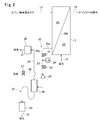
- FIG. 1 is a system diagram of an ozone gas-dissolved water supply system showing an example of an embodiment of a method for producing ozone gas-dissolved water and an electronic material cleaning method according to the present invention. It is a systematic diagram which shows an example of the condensed water discharge mechanism of the ozone melt
- the method for producing ozone gas-dissolved water of the present invention supplies a mixture gas of ozone gas and oxygen gas (hereinafter sometimes referred to as “ozone / oxygen mixture gas”) and degassed treated water to the ozone dissolver and mixes them.
- ozone / oxygen mixture gas a mixture gas of ozone gas and oxygen gas
- the amount of the mixed gas supplied to the ozone-dissolving part is the mixture when it is assumed that all the ozone in the mixed gas is decomposed into oxygen.
- the total amount of the dissolved oxygen gas concentration calculated from the amount of oxygen gas in the gas and the amount of degassed treated water and the concentration of dissolved oxygen gas in the degassed treated water is the use condition of the obtained ozone gas dissolved water It is characterized by being controlled so as to be lower than the saturation solubility of oxygen gas below.
- degassed treated water (hereinafter sometimes referred to as “feed water”) to be supplied to the ozone dissolving part has a water quality suitable for cleaning and a pH in order to maintain the ozone gas concentration of the obtained ozone gas dissolving water.
- feed water preferably neutral or less, and the hydrogen peroxide concentration is sufficiently low (preferably 10 ppb or less). It is desirable that impurities be removed and ultrapure water that has been deaerated and removed. Alternatively, pure water is used.
- the ozone / oxygen mixed gas dissolved in the feed water is preferably an ozone / oxygen mixed gas generated from an oxygen gas by an ozonizer.
- the oxygen gas supplied to the ozonizer may be supplied from an oxygen gas cylinder.
- a PSA (Pressure Swing Adsorption) oxygen concentrator may be used to extract oxygen gas from air in the atmosphere and supply this gas to an ozonizer to obtain a mixed gas of ozone gas and oxygen gas.
- a PSA oxygen concentrator and a gas cylinder may be used in combination.
- This method is inexpensive and advantageous without trouble such as replacement of a gas cylinder.
- the ozonizer is not particularly limited, and a water electrolysis type, an ultraviolet irradiation type or a discharge type is used.
- a discharge type that easily generates a large volume of high-concentration ozone gas at low cost is suitable.
- the ozone gas concentration in the mixed gas is 3 vol% (65 g / Nm 3 ) or more, especially 5 vol%. The above is preferable. However, the ozone gas concentration in the mixed gas is usually 20% by volume or less depending on the specifications of the ozonizer.
- the ozone gas dissolving efficiency in water is usually 50 to 60%, so that 40 to 50% of excess ozone gas is discharged and the ozone gas Waste and exhaust gas treatment become a problem.
- the dissolved gas concentration of the degassed treated water is 50% or less, particularly 10% or less, especially 1% or less of the saturated dissolved gas concentration at the water temperature of the feed water. It is preferable to deaerate.
- the feed water deaeration device is not particularly limited as long as it does not deteriorate the water quality, and a vacuum deaeration tower, a membrane deaeration device, or the like is used. Since it is compact and easy to manage, the aqueous phase can be dissolved by reducing the pressure of the gas-permeable membrane module, ie the gas-permeable membrane module in which the gas-phase and water-phase are separated through the gas-permeable membrane. It is preferable to use a depressurized membrane deaerator that moves the gas to the gas phase through the gas permeable membrane regardless of its components.
- the deaeration device does not necessarily need to be provided immediately before the ozone dissolving part, and may be upstream of that.
- the material of the water supply piping is not limited unless it deteriorates the quality of the water supply.
- a material such as CVP (vinyl chloride) or PVDF (polyvinylidene fluoride) having a low gas permeability is desirable, but this is not the case when a high deaeration level (for example, a dissolved oxygen gas concentration of 50 ppb or less) is not required.
- a high deaeration level for example, a dissolved oxygen gas concentration of 50 ppb or less
- the supply pipe of the mixed gas containing ozone gas and the ozone gas-dissolved water is made of a material having sufficient ozone resistance.
- This material may be PFA (tetrafluoroethylene / perfluoroalkyl vinyl ether copolymer resin), PTFE (polytetrafluoroethylene), or the like.
- the mixed gas supplied to the gas phase of the gas permeable membrane module in which the gas phase and the water phase are partitioned through the gas permeable membrane is transferred to the water phase through the gas permeable membrane and dissolved.
- a dissolved membrane module it is preferable to use a dissolved membrane module.
- the gas can be easily dissolved in water, and the dissolved gas concentration can be easily adjusted and managed.
- the ozone dissolving part such as a gas dissolving membrane module has sufficient ozone resistance, and those made of PTFE are usually used.
- the ozone dissolving part is not limited to the gas permeable membrane module.
- the ozone dissolution part is preferably one that can increase the dissolution efficiency by securing a sufficient time after dissolution, and may be one that is dissolved by bubbling or one that is dissolved by an ejector.
- the amount of the ozone / oxygen mixed gas supplied to the ozone dissolving part of the gas permeable membrane module or the like is based on the amount of oxygen gas and the amount of water supplied in the mixed gas assuming that all the ozone in the mixed gas is decomposed into oxygen.
- the sum of the calculated increase in the dissolved oxygen gas concentration of the obtained ozone gas dissolved water relative to the dissolved oxygen gas concentration of the feed water and the dissolved oxygen gas concentration of the feed water supplied to the ozone dissolving section (hereinafter, this total concentration is "Theoretical dissolved oxygen gas concentration of ozone gas-dissolved water”) may be referred to as the use of the obtained ozone gas-dissolved water, that is, the saturated solubility of oxygen gas (hereinafter, It may be referred to as “saturated oxygen gas concentration”).
- the theoretical dissolved oxygen gas concentration of ozone gas-dissolved water may be equal to or lower than the saturated oxygen gas concentration, and is usually set in the range of 50 to 100% with respect to the saturated oxygen gas concentration.
- the dissolved ozone gas concentration of the ozone gas-dissolved water obtained by controlling the mixed gas supply amount to the ozone dissolving part is calculated by the following calculation formula (1).
- D O3 1.5 ⁇ D O2 ⁇ C O3 (1)
- D O3 Dissolved ozone gas concentration (ppm) of ozone gas dissolved water
- D O2 Saturated oxygen gas concentration (ppm) under the use conditions of ozone gas dissolved water
- C O3 Ozone gas concentration (volume%) of the ozone / oxygen mixed gas supplied to the ozone dissolving part
- the ozone gas concentration of the ozone / oxygen mixed gas supplied to the ozone dissolving part is 7% by volume and the water temperature at the place where the ozone gas dissolved water is used is 25 ° C.
- the dissolved ozone gas concentration of the ozone gas dissolved water produced according to the present invention is not particularly limited, but is usually about 1 to 15 ppm, preferably about 2 to 10 ppm.
- the dissolved ozone gas concentration of the obtained ozone gas dissolved water depends on the ozone gas concentration of the mixed gas supplied to the ozone dissolving part. Therefore, if a high-concentration ozone gas-containing mixed gas of about 25% by volume can be supplied to the ozone-dissolving part, it is possible to produce even higher-concentration ozone gas-dissolved water.
- degassed treated water supplied to the ozone dissolving part, ozone gas dissolving water obtained from the ozone dissolving part, or ozone dissolving part An acidic gas or acid that lowers the pH of water may be supplied in the mixed gas to be supplied or directly into the ozone dissolving part and dissolved in water to adjust the pH of the water to an acid, for example, about pH 2-6.
- carbon dioxide gas is preferably used as the acid gas because it has little influence on the object to be cleaned.
- the electronic material cleaning method of the present invention the electronic material is cleaned by the ozone gas-dissolved water produced by the above-described method for producing ozone-gas-dissolved water of the present invention (hereinafter sometimes referred to as “the ozone gas-dissolved water of the present invention”). Is done.
- one or more agents such as chelating agents and surfactants can be added to the ozone gas-dissolved water used for cleaning to enhance the cleaning functionality, but the decomposition of ozone is promoted. It is important not to include substances such as alkali and hydrogen peroxide.
- cleaning method there is no particular limitation on the cleaning method, and conventionally known methods such as a single wafer cleaning method in which cleaning water to which ultrasonic waves are applied are sprayed on the object to be cleaned, and a method in which the object to be cleaned is immersed in cleaning water for cleaning Any of these methods can be employed.
- the frequency of the ultrasonic wave to be used is not particularly limited, but is preferably 10 KHz to 3 MHz used for general cleaning.
- the temperature of the washing water used for washing may be in the range of 10 to 90 ° C., and the temperature of the washing water is preferably determined depending on the object to be washed. In general, in the case of an object to be cleaned in which it is difficult to remove fine particles, the fine particle removability tends to be improved by increasing the water temperature. According to the ozone gas-dissolved water of the present invention, bubbling of oxygen gas can be suppressed even with high-concentration ozone gas-dissolved water. A cleaning effect can be obtained.
- the washing water temperature is near room temperature, for example, 20-60. Although it is preferable to set it as ° C, it is not necessarily limited to this.
- the material of the washing tank there is no particular limitation on the material of the washing tank, but usually a quartz or SUS material is used, and a quartz material is particularly preferably used in terms of ozone resistance.
- a sealed cleaning tank or pipe to prevent contamination of the cleaning water and maintain a high quality of the cleaning water over a long period of time.
- the cleaning water is produced by concentrating and manufacturing the cleaning water in one place without providing the cleaning water manufacturing apparatus individually for many cleaning machines.
- a surplus cleaning water that has not been used in the washer can be returned to the water tank, and a circulation system can be assembled that is sent to the washer again.
- the cleaning water used for cleaning is collected, impurities are removed so that there is no problem with the next cleaning, degassing is performed again, the required amount of mixed gas is dissolved, and a recovery circulation system is used that is reused for cleaning. May be. Since the dissolved ozone gas oxidizes and degrades the liquid contact member, it is desirable to introduce the dissolved ozone gas in the water after being decomposed by a method such as ultraviolet irradiation before being introduced into the circulation system.
- the water supply is supplied to the deaeration membrane module 1 through the pipe 11.
- the flow rate of the feed water that has been deaerated by the deaeration membrane module is measured by the flow meter 2, and is supplied to the gas dissolution membrane module 3, which is an ozone dissolution unit, through the pipe 12.
- the gas dissolution membrane module 3 which is an ozone dissolution unit, through the pipe 12.
- Oxygen gas from the PSA oxygen concentrator or the like is adjusted in flow rate by the oxygen gas flow rate adjusting mechanism 4 through the oxygen supply pipe 13 and supplied to the ozonizer 5 through the pipe 14.
- the oxygen gas flow rate is calculated from the amount of water obtained from the indicated value of the flow meter 2, and is controlled to a flow rate that is equal to or lower than the saturated oxygen gas concentration under the use conditions of the ozone gas dissolved water.
- FIG. 1 in order to supply an oxygen gas amount equal to or lower than the saturated oxygen gas concentration to the feed water sufficiently deaerated by the deaeration membrane module 1, all the ozone gas is decomposed at the place where the ozone gas dissolved water is used. Even if it becomes, the dissolved state is maintained without forming bubbles.
- the oxygen gas flow rate adjusting mechanism 4 is not limited, a mass flow controller (MFC) capable of precise and agile control is preferably used.
- MFC mass flow controller
- the ozone gas generated in the ozonizer 5 is sent as an ozone / oxygen mixed gas through the ozone gas supply pipe 15 to the gas dissolution membrane module 3 which is an ozone dissolution part, and is dissolved in the water supply.
- the gas dissolution membrane module 3 the ozone / oxygen mixed gas having a saturation solubility or lower is dissolved in the degassed feed water, so that the ozone / oxygen mixed gas supplied to the gas dissolution membrane module 3 is completely dissolved and the surplus gas is dissolved. Does not occur. For this reason, the gas-dissolving membrane module 3 is not provided with a surplus gas discharge system.
- the concentration of the ozone gas-dissolved water obtained by the gas-dissolving membrane module 3 is confirmed by the dissolved ozone concentration meter 6 and then supplied to the cleaning tank 7 through the pipe 16. Sonicated.
- the gas-dissolving membrane module 3 shown in FIG. 1 is not provided with a surplus gas discharge system, and thus is provided with a condensed water discharge mechanism for discharging condensed water generated on the primary side (mixed gas supply side) of the membrane. ing.
- the gas dissolution membrane module 3 is divided into a gas phase chamber (primary side) 3A and a liquid phase chamber (secondary side) 3B by a gas dissolution membrane 3M.
- An ozone / oxygen mixed gas supply pipe 15 from the ozonizer 5 is connected to the gas phase chamber 3A, and a water supply supply pipe 12 from the degassing membrane module 1 is connected to the liquid phase chamber 3B.
- a condensed water discharge pipe 20 is connected to the lower part of the gas phase chamber 3A.
- One end of the condensed water discharge pipe 20 is connected to the gas phase chamber 3A, and has a horizontal portion 20a extending horizontally and a hanging portion 20b hanging from the other end of the horizontal portion 20a.
- a first automatic valve 21 and a second automatic valve 22 are provided on the hanging part 20b in this order from the top to the bottom.
- a portion of the discharge pipe 20 between the first automatic valve 21 and the second automatic valve 22 serves as a storage unit 23, and a water level gauge (LS) 24 that detects the level of condensed water in the storage unit 23 is provided. Is provided.
- An ejector 25 is provided below the second automatic valve 22 in the hanging portion 2b, an air supply pipe 26 as a sweep gas is connected to the ejector 25, and a third automatic valve 27 is provided in the pipe 26. .
- the lower end of the condensed water discharge pipe 20b is connected to the gas-liquid separator 28.
- a separated gas discharge pipe 29 At the upper part of the gas-liquid separator 28, a separated gas discharge pipe 29, an ozone decomposer 30 for decomposing ozone in the separated gas, and a gas discharge pipe for discharging the ozone-decomposed gas as exhaust gas. 31 is connected.
- An activated carbon tower 33 is connected to the lower part of the gas-liquid separator 28 via a U-shaped tube 32 for gas trap, and a drainage discharge pipe 34 for discharging the effluent water of the activated carbon tower 33 is provided.
- the first automatic valve 21 is opened, the second automatic valve 22 and the third automatic valve 27 are closed, and the condensed water from the gas phase chamber 3A of the gas dissolution membrane module 3 is stored in the storage unit. 23.
- the water level gauge 24 detects that condensed water has accumulated in the reservoir 23 up to a predetermined water level
- the first automatic valve 21 is closed, the second automatic valve 22 is opened, and then the third automatic valve 27 is opened. Is opened and air is sent from the pipe 26 to the ejector 25, and the condensed water in the reservoir 23 is fed from the ejector 25 to the gas-liquid separator 28.
- the gas-liquid separator 28 separates condensed water (ozone gas-dissolved water) and gas (ozone / oxygen mixed gas flowing together with the condensed water and mixed gas released from the condensed water).
- the gas separated by the gas-liquid separator 28 is discharged from the gas discharge pipe 29, and after ozone in the gas is decomposed by the ozone decomposer 30, it is discharged out of the system through the pipe 31.
- the condensed water separated by the gas-liquid separator 28 passes through a U-tube 32 for gas trap, decomposes dissolved ozone gas in water in the activated carbon tower 33, and then is discharged out of the system as drainage from the pipe 34. .
- the second automatic valve 22 When the condensed water in the storage unit 23 is discharged in this way and the water level gauge 24 detects that the water level in the storage unit 23 has dropped to a predetermined position, the second automatic valve 22 is closed, and then the third The automatic valve 27 is opened, then the first automatic valve 21 is opened, and the condensed water from the gas phase chamber 3A of the gas dissolving membrane module 3 is again received and stored in the storage unit 23. Thereafter, the same operation is repeated.
- the switching of the first to third automatic valves 21, 22, and 27 is automatically performed by a signal output from the water level gauge 24 of the storage unit 23.
- the piping of such a condensed water discharge mechanism is composed of PFA, PTFE, etc. that are excellent in ozone resistance.
- Example 1 According to the ozone gas-dissolved water supply system shown in FIG. 1, the ozone gas-dissolved water was manufactured and the object to be cleaned was cleaned.
- Deaeration membrane module “Liquicel G248” manufactured by Polypore Gas dissolution membrane module: “GNH-01R” manufactured by Japan Gore-Tex Ozonizer: “GR-RB” manufactured by Sumitomo Precision Industries
- Water was used as deionized membrane module 1 as feed water (pure water), and water having a dissolved oxygen gas concentration of about 10 ppb was supplied to the gas-dissolved membrane module 3.
- the ozone gas concentration of the mixed gas supplied to the gas dissolving membrane module 3 is 200 g / Nm 3 (9.3 vol%)
- the raw material oxygen gas to the ozonizer 4 was mixed and supplied at a flow rate of 50 ppm (50 NmL / min) when carbon dioxide was dissolved in water, so that the pH of the ozone gas-dissolved water was adjusted to about 5. .
- the cleaning object was cleaned using the ozone water dissolved in this way.
- a silicon wafer whose surface was contaminated with organic matter and fine particles was used for one week in a clean room.
- the cleaning tank was a batch cleaning tank with ultrasonic waves (ultrasonic frequency: 750 KHz), and the cleaning time was 3 minutes.
- the cleaning effect was evaluated by measuring the number of fine particles having a particle diameter of 0.12 ⁇ m or more on the silicon wafer before and after cleaning using a defect inspection apparatus “WM-1500” manufactured by Topcon Corporation and calculating the removal rate.
- Example 1 In Example 1, pure water as feed water was supplied to the gas dissolution membrane module without degassing. The dissolved oxygen gas concentration of this feed water was about 8 ppm, and other dissolved nitrogen gas was dissolved about 12 ppm, and the gas was almost saturated. This water supply is supplied to the gas dissolution membrane module, the surplus gas is discharged from the primary side of the gas dissolution membrane module, and the exhaust gas pressure is adjusted to prepare ozone gas dissolved water with a dissolved ozone gas concentration of 5.58 ppm and wash tank Water was sent to Other than that was carried out in the same manner as in Example 1.
- Comparative Example 1 When the ozone gas-dissolved water obtained in Example 1 and the ozone gas-dissolved water obtained in Comparative Example 1 were respectively applied to the single-wafer cleaning ultrasonic nozzle for cleaning each wafer one by one, Comparative Example 1 In the ozone gas-dissolved water, the ultrasonic vibrator is damaged by air vibration due to the presence of bubbles. However, in the ozone gas-dissolved water of Example 1, formation of air bubbles is suppressed, air vibration does not occur, and there is no damage. Washing was possible.
Landscapes
- Life Sciences & Earth Sciences (AREA)
- Hydrology & Water Resources (AREA)
- Engineering & Computer Science (AREA)
- Environmental & Geological Engineering (AREA)
- Water Supply & Treatment (AREA)
- Chemical & Material Sciences (AREA)
- Organic Chemistry (AREA)
- Cleaning Or Drying Semiconductors (AREA)
- Treatment Of Water By Oxidation Or Reduction (AREA)
- Cleaning By Liquid Or Steam (AREA)
- Oxygen, Ozone, And Oxides In General (AREA)
Abstract
Description
本発明のオゾンガス溶解水の製造方法は、オゾンガス及び酸素ガスの混合ガス(以下「オゾン/酸素混合ガス」と称す場合がある。)と脱気処理水とをオゾン溶解部に供給して該混合ガスを該供給水に溶解させてオゾンガス溶解水を製造する方法において、該オゾン溶解部に供給する該混合ガス量を、該混合ガス中のオゾンがすべて酸素に分解したと仮定した場合の該混合ガス中の酸素ガス量と該脱気処理水量とから算出される溶存酸素ガス濃度の増加分と、該脱気処理水の溶存酸素ガス濃度との合計が、得られたオゾンガス溶解水の使用条件下における酸素ガスの飽和溶解度以下となるように制御することを特徴とする。
(1) オゾンガス及びその原料である酸素ガス使用量を必要最低限に抑えてガス供給コスト、オゾン発生電力を低減することができる。
(2) 排気される余剰ガスがないため、その無害化処理が不要となり、装置の簡素化、コストダウンを図ることができる。これにより、オゾンガス溶解水の製造コストが低減される。
DO2≧DO+(G/W)
となるように混合ガス量が制御される。(G/W)は、DO2、DOと単位を合わせた酸素ガス濃度である。
DO3=1.5×DO2×CO3 ・・・(1)
DO3:オゾンガス溶解水の溶存オゾンガス濃度(ppm)
DO2:オゾンガス溶解水の使用条件下での飽和酸素ガス濃度(ppm)
CO3:オゾン溶解部に供給するオゾン/酸素混合ガスのオゾンガス濃度(体積%)
DO3=1.5×DO2×CO3=1.5×40×0.07=4.2ppm
となる。
本発明の電子材料の洗浄方法では、上述の本発明のオゾンガス溶解水の製造方法により製造されたオゾンガス溶解水(以下「本発明のオゾンガス溶解水」と称す場合がある。)により電子材料が洗浄される。
以下に図1を参照して、本発明のオゾンガス溶解水の製造方法及び電子材料の洗浄方法を実施するためのオゾンガス溶解水の供給システムの一例を説明する。
脱気膜モジュールで脱気処理された給水は流量計2にて流量が測定され、配管12を経てオゾン溶解部であるガス溶解膜モジュール3に供給される。流量計2には制限はないが、流量指示値に応じて、オゾナイザ5への酸素ガス流量を調整することができるものが望ましく、指示値が伝送出力できるものが好ましい。
図2において、図1に示す部材と同一機能を奏する部材には同一符号を付してある。
図1に示すオゾンガス溶解水の供給システムに従って、オゾンガス溶解水の製造と被洗浄物の洗浄を行った。
脱気膜モジュール:ポリポア社製「リキセルG248」
ガス溶解膜モジュール:ジャパンゴアテックス社製「GNH-01R」
オゾナイザ:住友精密工業社製「GR-RB」
10×40/32×22.4=280NmL/min
実施例1において、給水である純水を脱気を行わずにガス溶解膜モジュールへ供給した。この給水の溶存酸素ガス濃度は8ppm程度で他に溶存窒素ガスが12ppm程度溶解しており、ほぼガス飽和状態であった。この給水をガス溶解膜モジュールに送給し、ガス溶解膜モジュールの一次側から余剰ガスを出し、排出ガス圧力を調整することで、溶存オゾンガス濃度5.58ppmのオゾンガス溶解水を調製して洗浄槽へ送水した。それ以外は実施例1と同様に行った。
本出願は、2012年11月1日付で出願された日本特許出願(特願2012-241891)に基づいており、その全体が引用により援用される。
Claims (7)
- オゾンガス及び酸素ガスの混合ガスと脱気処理水とをオゾン溶解部に供給して該混合ガスを該脱気処理水に溶解させてオゾンガス溶解水を製造する方法において、
該オゾン溶解部に供給する該混合ガス量を、該混合ガス中のオゾンがすべて酸素に分解したと仮定した場合の該混合ガス中の酸素ガス量と該脱気処理水量とから算出される溶存酸素ガス濃度の増加分と、該脱気処理水の溶存酸素ガス濃度との合計が、得られたオゾンガス溶解水の使用条件下における酸素ガスの飽和溶解度以下となるように制御することを特徴とするオゾンガス溶解水の製造方法。 - 請求項1において、前記混合ガスのオゾンガス濃度が3体積%以上であることを特徴とするオゾンガス溶解水の製造方法。
- 請求項1において、前記混合ガスが、酸素ガスからオゾンガスを発生させるオゾナイザで得られた混合ガスであり、該オゾナイザの入口酸素ガス量を調整することにより、前記オゾン溶解部に供給する混合ガス量を制御することを特徴とするオゾンガス溶解水の製造方法。
- 請求項1において、前記オゾンガス溶解水のpHを中性以下として該オゾンガス溶解水中の溶存オゾンガスの自己分解を抑制するためのガスを、前記オゾン溶解部の前段、後段及び該オゾン溶解部のいずれかにおいて前記脱気処理水又はオゾンガス溶解水中に溶解させることを特徴とするオゾンガス溶解水の製造方法。
- 請求項1において、前記オゾンガス溶解水の溶存オゾンガス濃度が1~15ppmであることを特徴とするオゾンガス溶解水の製造方法。
- 請求項1ないし5のいずれか1項に記載のオゾンガス溶解水の製造方法で製造されたオゾンガス溶解水を用いて電子材料を洗浄することを特徴とする電子材料の洗浄方法。
- 請求項6において、前記オゾンガス溶解水を用いて超音波洗浄を行うことを特徴とする電子材料の洗浄方法。
Priority Applications (4)
| Application Number | Priority Date | Filing Date | Title |
|---|---|---|---|
| US14/439,126 US20150303053A1 (en) | 2012-11-01 | 2013-10-10 | Method for producing ozone gas-dissolved water and method for cleaning electronic material |
| SG11201503197WA SG11201503197WA (en) | 2012-11-01 | 2013-10-10 | Method for producing ozone gas-dissolved water and method for cleaning electronic material |
| KR1020157008238A KR20150079580A (ko) | 2012-11-01 | 2013-10-10 | 오존 가스 용해수의 제조 방법, 및 전자 재료의 세정 방법 |
| CN201380057522.9A CN104995722B (zh) | 2012-11-01 | 2013-10-10 | 臭氧气体溶解水的制造方法及电子材料的洗净方法 |
Applications Claiming Priority (2)
| Application Number | Priority Date | Filing Date | Title |
|---|---|---|---|
| JP2012241891A JP2014093357A (ja) | 2012-11-01 | 2012-11-01 | オゾンガス溶解水の製造方法、及び電子材料の洗浄方法 |
| JP2012-241891 | 2012-11-01 |
Publications (1)
| Publication Number | Publication Date |
|---|---|
| WO2014069203A1 true WO2014069203A1 (ja) | 2014-05-08 |
Family
ID=50627117
Family Applications (1)
| Application Number | Title | Priority Date | Filing Date |
|---|---|---|---|
| PCT/JP2013/077570 Ceased WO2014069203A1 (ja) | 2012-11-01 | 2013-10-10 | オゾンガス溶解水の製造方法、及び電子材料の洗浄方法 |
Country Status (7)
| Country | Link |
|---|---|
| US (1) | US20150303053A1 (ja) |
| JP (1) | JP2014093357A (ja) |
| KR (1) | KR20150079580A (ja) |
| CN (1) | CN104995722B (ja) |
| SG (1) | SG11201503197WA (ja) |
| TW (1) | TWI601695B (ja) |
| WO (1) | WO2014069203A1 (ja) |
Cited By (1)
| Publication number | Priority date | Publication date | Assignee | Title |
|---|---|---|---|---|
| CN106714954A (zh) * | 2014-09-18 | 2017-05-24 | 株式会社荏原制作所 | 气体溶解水制造装置及制造方法 |
Families Citing this family (7)
| Publication number | Priority date | Publication date | Assignee | Title |
|---|---|---|---|---|
| KR101776017B1 (ko) | 2015-10-27 | 2017-09-07 | 세메스 주식회사 | 용존 오존 제거 유닛 및 이를 포함하는 기판 처리 장치, 용존 오존 제거 방법, 기판 세정 방법 |
| JP6428806B2 (ja) * | 2017-02-07 | 2018-11-28 | 栗田工業株式会社 | 半導体基板の洗浄装置及び半導体基板の洗浄方法 |
| US10851000B2 (en) * | 2018-03-28 | 2020-12-01 | L'Air Liquide, Société Anonyme pour l'Etude et l'Exploitation des Procédés Georges Claude | Systems for producing high-concentration of dissolved ozone in liquid media |
| US11084744B2 (en) | 2018-03-28 | 2021-08-10 | L'Air Liquide, Société Anonyme pour l'Etude et l'Exploitation des Procédés Georges Claude | Method for mixing gas-free liquid oxidant with process liquid |
| US11434153B2 (en) | 2018-03-28 | 2022-09-06 | L'Air Liquide, Société Anonyme pour l'Etude et l'Exploitation des Procédés George Claude | Separation of ozone oxidation in liquid media into three unit operations for process optimization |
| JP6635459B1 (ja) * | 2018-05-02 | 2020-01-22 | 国立大学法人東北大学 | オゾン水の製造法 |
| US12012575B2 (en) * | 2019-03-26 | 2024-06-18 | Fujimi Incorporated | Composition for surface treatment, method for producing the same, surface treatment method, and method for producing semiconductor substrate |
Citations (2)
| Publication number | Priority date | Publication date | Assignee | Title |
|---|---|---|---|---|
| JP2000197815A (ja) * | 1999-01-08 | 2000-07-18 | Kurita Water Ind Ltd | オゾン溶解水の製造装置 |
| JP2012146690A (ja) * | 2009-03-31 | 2012-08-02 | Kurita Water Ind Ltd | 電子材料洗浄方法及び電子材料洗浄装置 |
Family Cites Families (2)
| Publication number | Priority date | Publication date | Assignee | Title |
|---|---|---|---|---|
| JP2002316027A (ja) * | 2001-04-19 | 2002-10-29 | Ebara Corp | ガス溶解水製造装置、およびその方法、超音波洗浄装置、およびその方法 |
| JP2010234298A (ja) * | 2009-03-31 | 2010-10-21 | Kurita Water Ind Ltd | ガス溶解水供給装置及びガス溶解水の製造方法 |
-
2012
- 2012-11-01 JP JP2012241891A patent/JP2014093357A/ja active Pending
-
2013
- 2013-10-10 CN CN201380057522.9A patent/CN104995722B/zh not_active Expired - Fee Related
- 2013-10-10 WO PCT/JP2013/077570 patent/WO2014069203A1/ja not_active Ceased
- 2013-10-10 KR KR1020157008238A patent/KR20150079580A/ko not_active Ceased
- 2013-10-10 US US14/439,126 patent/US20150303053A1/en not_active Abandoned
- 2013-10-10 SG SG11201503197WA patent/SG11201503197WA/en unknown
- 2013-10-23 TW TW102138254A patent/TWI601695B/zh active
Patent Citations (2)
| Publication number | Priority date | Publication date | Assignee | Title |
|---|---|---|---|---|
| JP2000197815A (ja) * | 1999-01-08 | 2000-07-18 | Kurita Water Ind Ltd | オゾン溶解水の製造装置 |
| JP2012146690A (ja) * | 2009-03-31 | 2012-08-02 | Kurita Water Ind Ltd | 電子材料洗浄方法及び電子材料洗浄装置 |
Cited By (1)
| Publication number | Priority date | Publication date | Assignee | Title |
|---|---|---|---|---|
| CN106714954A (zh) * | 2014-09-18 | 2017-05-24 | 株式会社荏原制作所 | 气体溶解水制造装置及制造方法 |
Also Published As
| Publication number | Publication date |
|---|---|
| TWI601695B (zh) | 2017-10-11 |
| KR20150079580A (ko) | 2015-07-08 |
| TW201431797A (zh) | 2014-08-16 |
| CN104995722A (zh) | 2015-10-21 |
| CN104995722B (zh) | 2018-08-24 |
| US20150303053A1 (en) | 2015-10-22 |
| JP2014093357A (ja) | 2014-05-19 |
| SG11201503197WA (en) | 2015-06-29 |
Similar Documents
| Publication | Publication Date | Title |
|---|---|---|
| WO2014069203A1 (ja) | オゾンガス溶解水の製造方法、及び電子材料の洗浄方法 | |
| US8999069B2 (en) | Method for producing cleaning water for an electronic material | |
| JP5072062B2 (ja) | 水素ガス溶解洗浄水の製造方法、製造装置及び洗浄装置 | |
| JP5251184B2 (ja) | ガス溶解水供給システム | |
| JP5441714B2 (ja) | 純水の製造方法およびその装置、オゾン水製造方法およびその装置、並びに洗浄方法およびその装置 | |
| JP5380870B2 (ja) | ガス溶解水の製造方法及び装置 | |
| JP2016076588A (ja) | 炭酸ガス溶解水供給システム、炭酸ガス溶解水供給方法、およびイオン交換装置 | |
| JP3639102B2 (ja) | ウェット処理装置 | |
| JP5320665B2 (ja) | 超純水製造装置および方法 | |
| JP4273440B2 (ja) | 電子材料用洗浄水及び電子材料の洗浄方法 | |
| JP4756327B2 (ja) | 窒素ガス溶解水の製造方法 | |
| JP2004050019A (ja) | 超純水供給設備 | |
| JP2000354857A (ja) | 機能水製造方法及び装置 | |
| JPH1129794A (ja) | 電子材料用洗浄水、その製造方法及び電子材料の洗浄方法 | |
| JP2017202474A (ja) | オゾン溶解水製造装置 | |
| JP2010046570A (ja) | 超音波処理装置用供給液の製造装置、超音波処理装置用供給液の製造方法及び超音波処理システム | |
| JP3914624B2 (ja) | 電子材料用洗浄水の再利用方法 | |
| JP2003340458A (ja) | 機能水の回収方法 | |
| JP2000262992A (ja) | 基板の洗浄方法 | |
| JP7052423B2 (ja) | オゾン溶解水の製造装置及びこれを用いたオゾン溶解水の製造方法 | |
| JP2005186067A (ja) | オゾン含有超純水供給方法及び装置 | |
| JP2012186348A (ja) | 電子材料用洗浄水、電子材料の洗浄方法及びガス溶解水の供給システム | |
| JP5857835B2 (ja) | ガス溶解水供給システム | |
| JP2001062412A (ja) | 洗浄方法、洗浄液の製造方法、洗浄液、および洗浄液の製造装置 |
Legal Events
| Date | Code | Title | Description |
|---|---|---|---|
| 121 | Ep: the epo has been informed by wipo that ep was designated in this application |
Ref document number: 13851207 Country of ref document: EP Kind code of ref document: A1 |
|
| ENP | Entry into the national phase |
Ref document number: 20157008238 Country of ref document: KR Kind code of ref document: A |
|
| WWE | Wipo information: entry into national phase |
Ref document number: 14439126 Country of ref document: US |
|
| NENP | Non-entry into the national phase |
Ref country code: DE |
|
| 122 | Ep: pct application non-entry in european phase |
Ref document number: 13851207 Country of ref document: EP Kind code of ref document: A1 |