WO2014068868A1 - ニッケル水素蓄電池及び蓄電池システム - Google Patents
ニッケル水素蓄電池及び蓄電池システム Download PDFInfo
- Publication number
- WO2014068868A1 WO2014068868A1 PCT/JP2013/006085 JP2013006085W WO2014068868A1 WO 2014068868 A1 WO2014068868 A1 WO 2014068868A1 JP 2013006085 W JP2013006085 W JP 2013006085W WO 2014068868 A1 WO2014068868 A1 WO 2014068868A1
- Authority
- WO
- WIPO (PCT)
- Prior art keywords
- storage battery
- nickel
- metal hydride
- positive electrode
- battery
- Prior art date
- Legal status (The legal status is an assumption and is not a legal conclusion. Google has not performed a legal analysis and makes no representation as to the accuracy of the status listed.)
- Ceased
Links
Images

Classifications
-
- H—ELECTRICITY
- H01—ELECTRIC ELEMENTS
- H01M—PROCESSES OR MEANS, e.g. BATTERIES, FOR THE DIRECT CONVERSION OF CHEMICAL ENERGY INTO ELECTRICAL ENERGY
- H01M10/00—Secondary cells; Manufacture thereof
- H01M10/34—Gastight accumulators
- H01M10/345—Gastight metal hydride accumulators
-
- H—ELECTRICITY
- H01—ELECTRIC ELEMENTS
- H01M—PROCESSES OR MEANS, e.g. BATTERIES, FOR THE DIRECT CONVERSION OF CHEMICAL ENERGY INTO ELECTRICAL ENERGY
- H01M10/00—Secondary cells; Manufacture thereof
- H01M10/06—Lead-acid accumulators
-
- B—PERFORMING OPERATIONS; TRANSPORTING
- B60—VEHICLES IN GENERAL
- B60L—PROPULSION OF ELECTRICALLY-PROPELLED VEHICLES; SUPPLYING ELECTRIC POWER FOR AUXILIARY EQUIPMENT OF ELECTRICALLY-PROPELLED VEHICLES; ELECTRODYNAMIC BRAKE SYSTEMS FOR VEHICLES IN GENERAL; MAGNETIC SUSPENSION OR LEVITATION FOR VEHICLES; MONITORING OPERATING VARIABLES OF ELECTRICALLY-PROPELLED VEHICLES; ELECTRIC SAFETY DEVICES FOR ELECTRICALLY-PROPELLED VEHICLES
- B60L15/00—Methods, circuits, or devices for controlling the traction-motor speed of electrically-propelled vehicles
- B60L15/20—Methods, circuits, or devices for controlling the traction-motor speed of electrically-propelled vehicles for control of the vehicle or its driving motor to achieve a desired performance, e.g. speed, torque, programmed variation of speed
-
- B—PERFORMING OPERATIONS; TRANSPORTING
- B60—VEHICLES IN GENERAL
- B60L—PROPULSION OF ELECTRICALLY-PROPELLED VEHICLES; SUPPLYING ELECTRIC POWER FOR AUXILIARY EQUIPMENT OF ELECTRICALLY-PROPELLED VEHICLES; ELECTRODYNAMIC BRAKE SYSTEMS FOR VEHICLES IN GENERAL; MAGNETIC SUSPENSION OR LEVITATION FOR VEHICLES; MONITORING OPERATING VARIABLES OF ELECTRICALLY-PROPELLED VEHICLES; ELECTRIC SAFETY DEVICES FOR ELECTRICALLY-PROPELLED VEHICLES
- B60L50/00—Electric propulsion with power supplied within the vehicle
- B60L50/10—Electric propulsion with power supplied within the vehicle using propulsion power supplied by engine-driven generators, e.g. generators driven by combustion engines
- B60L50/16—Electric propulsion with power supplied within the vehicle using propulsion power supplied by engine-driven generators, e.g. generators driven by combustion engines with provision for separate direct mechanical propulsion
-
- B—PERFORMING OPERATIONS; TRANSPORTING
- B60—VEHICLES IN GENERAL
- B60L—PROPULSION OF ELECTRICALLY-PROPELLED VEHICLES; SUPPLYING ELECTRIC POWER FOR AUXILIARY EQUIPMENT OF ELECTRICALLY-PROPELLED VEHICLES; ELECTRODYNAMIC BRAKE SYSTEMS FOR VEHICLES IN GENERAL; MAGNETIC SUSPENSION OR LEVITATION FOR VEHICLES; MONITORING OPERATING VARIABLES OF ELECTRICALLY-PROPELLED VEHICLES; ELECTRIC SAFETY DEVICES FOR ELECTRICALLY-PROPELLED VEHICLES
- B60L50/00—Electric propulsion with power supplied within the vehicle
- B60L50/50—Electric propulsion with power supplied within the vehicle using propulsion power supplied by batteries or fuel cells
- B60L50/60—Electric propulsion with power supplied within the vehicle using propulsion power supplied by batteries or fuel cells using power supplied by batteries
- B60L50/64—Constructional details of batteries specially adapted for electric vehicles
-
- B—PERFORMING OPERATIONS; TRANSPORTING
- B60—VEHICLES IN GENERAL
- B60L—PROPULSION OF ELECTRICALLY-PROPELLED VEHICLES; SUPPLYING ELECTRIC POWER FOR AUXILIARY EQUIPMENT OF ELECTRICALLY-PROPELLED VEHICLES; ELECTRODYNAMIC BRAKE SYSTEMS FOR VEHICLES IN GENERAL; MAGNETIC SUSPENSION OR LEVITATION FOR VEHICLES; MONITORING OPERATING VARIABLES OF ELECTRICALLY-PROPELLED VEHICLES; ELECTRIC SAFETY DEVICES FOR ELECTRICALLY-PROPELLED VEHICLES
- B60L58/00—Methods or circuit arrangements for monitoring or controlling batteries or fuel cells, specially adapted for electric vehicles
- B60L58/10—Methods or circuit arrangements for monitoring or controlling batteries or fuel cells, specially adapted for electric vehicles for monitoring or controlling batteries
- B60L58/18—Methods or circuit arrangements for monitoring or controlling batteries or fuel cells, specially adapted for electric vehicles for monitoring or controlling batteries of two or more battery modules
- B60L58/20—Methods or circuit arrangements for monitoring or controlling batteries or fuel cells, specially adapted for electric vehicles for monitoring or controlling batteries of two or more battery modules having different nominal voltages
-
- B—PERFORMING OPERATIONS; TRANSPORTING
- B60—VEHICLES IN GENERAL
- B60L—PROPULSION OF ELECTRICALLY-PROPELLED VEHICLES; SUPPLYING ELECTRIC POWER FOR AUXILIARY EQUIPMENT OF ELECTRICALLY-PROPELLED VEHICLES; ELECTRODYNAMIC BRAKE SYSTEMS FOR VEHICLES IN GENERAL; MAGNETIC SUSPENSION OR LEVITATION FOR VEHICLES; MONITORING OPERATING VARIABLES OF ELECTRICALLY-PROPELLED VEHICLES; ELECTRIC SAFETY DEVICES FOR ELECTRICALLY-PROPELLED VEHICLES
- B60L58/00—Methods or circuit arrangements for monitoring or controlling batteries or fuel cells, specially adapted for electric vehicles
- B60L58/10—Methods or circuit arrangements for monitoring or controlling batteries or fuel cells, specially adapted for electric vehicles for monitoring or controlling batteries
- B60L58/18—Methods or circuit arrangements for monitoring or controlling batteries or fuel cells, specially adapted for electric vehicles for monitoring or controlling batteries of two or more battery modules
- B60L58/21—Methods or circuit arrangements for monitoring or controlling batteries or fuel cells, specially adapted for electric vehicles for monitoring or controlling batteries of two or more battery modules having the same nominal voltage
-
- B—PERFORMING OPERATIONS; TRANSPORTING
- B60—VEHICLES IN GENERAL
- B60L—PROPULSION OF ELECTRICALLY-PROPELLED VEHICLES; SUPPLYING ELECTRIC POWER FOR AUXILIARY EQUIPMENT OF ELECTRICALLY-PROPELLED VEHICLES; ELECTRODYNAMIC BRAKE SYSTEMS FOR VEHICLES IN GENERAL; MAGNETIC SUSPENSION OR LEVITATION FOR VEHICLES; MONITORING OPERATING VARIABLES OF ELECTRICALLY-PROPELLED VEHICLES; ELECTRIC SAFETY DEVICES FOR ELECTRICALLY-PROPELLED VEHICLES
- B60L7/00—Electrodynamic brake systems for vehicles in general
- B60L7/10—Dynamic electric regenerative braking
- B60L7/12—Dynamic electric regenerative braking for vehicles propelled by DC motors
-
- H—ELECTRICITY
- H01—ELECTRIC ELEMENTS
- H01M—PROCESSES OR MEANS, e.g. BATTERIES, FOR THE DIRECT CONVERSION OF CHEMICAL ENERGY INTO ELECTRICAL ENERGY
- H01M10/00—Secondary cells; Manufacture thereof
- H01M10/24—Alkaline accumulators
- H01M10/26—Selection of materials as electrolytes
-
- B—PERFORMING OPERATIONS; TRANSPORTING
- B60—VEHICLES IN GENERAL
- B60L—PROPULSION OF ELECTRICALLY-PROPELLED VEHICLES; SUPPLYING ELECTRIC POWER FOR AUXILIARY EQUIPMENT OF ELECTRICALLY-PROPELLED VEHICLES; ELECTRODYNAMIC BRAKE SYSTEMS FOR VEHICLES IN GENERAL; MAGNETIC SUSPENSION OR LEVITATION FOR VEHICLES; MONITORING OPERATING VARIABLES OF ELECTRICALLY-PROPELLED VEHICLES; ELECTRIC SAFETY DEVICES FOR ELECTRICALLY-PROPELLED VEHICLES
- B60L2240/00—Control parameters of input or output; Target parameters
- B60L2240/40—Drive Train control parameters
- B60L2240/54—Drive Train control parameters related to batteries
- B60L2240/545—Temperature
-
- B—PERFORMING OPERATIONS; TRANSPORTING
- B60—VEHICLES IN GENERAL
- B60L—PROPULSION OF ELECTRICALLY-PROPELLED VEHICLES; SUPPLYING ELECTRIC POWER FOR AUXILIARY EQUIPMENT OF ELECTRICALLY-PROPELLED VEHICLES; ELECTRODYNAMIC BRAKE SYSTEMS FOR VEHICLES IN GENERAL; MAGNETIC SUSPENSION OR LEVITATION FOR VEHICLES; MONITORING OPERATING VARIABLES OF ELECTRICALLY-PROPELLED VEHICLES; ELECTRIC SAFETY DEVICES FOR ELECTRICALLY-PROPELLED VEHICLES
- B60L2240/00—Control parameters of input or output; Target parameters
- B60L2240/40—Drive Train control parameters
- B60L2240/54—Drive Train control parameters related to batteries
- B60L2240/547—Voltage
-
- B—PERFORMING OPERATIONS; TRANSPORTING
- B60—VEHICLES IN GENERAL
- B60L—PROPULSION OF ELECTRICALLY-PROPELLED VEHICLES; SUPPLYING ELECTRIC POWER FOR AUXILIARY EQUIPMENT OF ELECTRICALLY-PROPELLED VEHICLES; ELECTRODYNAMIC BRAKE SYSTEMS FOR VEHICLES IN GENERAL; MAGNETIC SUSPENSION OR LEVITATION FOR VEHICLES; MONITORING OPERATING VARIABLES OF ELECTRICALLY-PROPELLED VEHICLES; ELECTRIC SAFETY DEVICES FOR ELECTRICALLY-PROPELLED VEHICLES
- B60L2240/00—Control parameters of input or output; Target parameters
- B60L2240/40—Drive Train control parameters
- B60L2240/54—Drive Train control parameters related to batteries
- B60L2240/549—Current
-
- B—PERFORMING OPERATIONS; TRANSPORTING
- B60—VEHICLES IN GENERAL
- B60L—PROPULSION OF ELECTRICALLY-PROPELLED VEHICLES; SUPPLYING ELECTRIC POWER FOR AUXILIARY EQUIPMENT OF ELECTRICALLY-PROPELLED VEHICLES; ELECTRODYNAMIC BRAKE SYSTEMS FOR VEHICLES IN GENERAL; MAGNETIC SUSPENSION OR LEVITATION FOR VEHICLES; MONITORING OPERATING VARIABLES OF ELECTRICALLY-PROPELLED VEHICLES; ELECTRIC SAFETY DEVICES FOR ELECTRICALLY-PROPELLED VEHICLES
- B60L2260/00—Operating Modes
- B60L2260/20—Drive modes; Transition between modes
- B60L2260/26—Transition between different drive modes
-
- H—ELECTRICITY
- H01—ELECTRIC ELEMENTS
- H01M—PROCESSES OR MEANS, e.g. BATTERIES, FOR THE DIRECT CONVERSION OF CHEMICAL ENERGY INTO ELECTRICAL ENERGY
- H01M2220/00—Batteries for particular applications
- H01M2220/20—Batteries in motive systems, e.g. vehicle, ship, plane
-
- H—ELECTRICITY
- H01—ELECTRIC ELEMENTS
- H01M—PROCESSES OR MEANS, e.g. BATTERIES, FOR THE DIRECT CONVERSION OF CHEMICAL ENERGY INTO ELECTRICAL ENERGY
- H01M2300/00—Electrolytes
- H01M2300/0002—Aqueous electrolytes
- H01M2300/0014—Alkaline electrolytes
-
- H—ELECTRICITY
- H01—ELECTRIC ELEMENTS
- H01M—PROCESSES OR MEANS, e.g. BATTERIES, FOR THE DIRECT CONVERSION OF CHEMICAL ENERGY INTO ELECTRICAL ENERGY
- H01M4/00—Electrodes
- H01M4/02—Electrodes composed of, or comprising, active material
- H01M4/24—Electrodes for alkaline accumulators
- H01M4/242—Hydrogen storage electrodes
-
- Y—GENERAL TAGGING OF NEW TECHNOLOGICAL DEVELOPMENTS; GENERAL TAGGING OF CROSS-SECTIONAL TECHNOLOGIES SPANNING OVER SEVERAL SECTIONS OF THE IPC; TECHNICAL SUBJECTS COVERED BY FORMER USPC CROSS-REFERENCE ART COLLECTIONS [XRACs] AND DIGESTS
- Y02—TECHNOLOGIES OR APPLICATIONS FOR MITIGATION OR ADAPTATION AGAINST CLIMATE CHANGE
- Y02E—REDUCTION OF GREENHOUSE GAS [GHG] EMISSIONS, RELATED TO ENERGY GENERATION, TRANSMISSION OR DISTRIBUTION
- Y02E60/00—Enabling technologies; Technologies with a potential or indirect contribution to GHG emissions mitigation
- Y02E60/10—Energy storage using batteries
-
- Y—GENERAL TAGGING OF NEW TECHNOLOGICAL DEVELOPMENTS; GENERAL TAGGING OF CROSS-SECTIONAL TECHNOLOGIES SPANNING OVER SEVERAL SECTIONS OF THE IPC; TECHNICAL SUBJECTS COVERED BY FORMER USPC CROSS-REFERENCE ART COLLECTIONS [XRACs] AND DIGESTS
- Y02—TECHNOLOGIES OR APPLICATIONS FOR MITIGATION OR ADAPTATION AGAINST CLIMATE CHANGE
- Y02T—CLIMATE CHANGE MITIGATION TECHNOLOGIES RELATED TO TRANSPORTATION
- Y02T10/00—Road transport of goods or passengers
- Y02T10/60—Other road transportation technologies with climate change mitigation effect
- Y02T10/64—Electric machine technologies in electromobility
-
- Y—GENERAL TAGGING OF NEW TECHNOLOGICAL DEVELOPMENTS; GENERAL TAGGING OF CROSS-SECTIONAL TECHNOLOGIES SPANNING OVER SEVERAL SECTIONS OF THE IPC; TECHNICAL SUBJECTS COVERED BY FORMER USPC CROSS-REFERENCE ART COLLECTIONS [XRACs] AND DIGESTS
- Y02—TECHNOLOGIES OR APPLICATIONS FOR MITIGATION OR ADAPTATION AGAINST CLIMATE CHANGE
- Y02T—CLIMATE CHANGE MITIGATION TECHNOLOGIES RELATED TO TRANSPORTATION
- Y02T10/00—Road transport of goods or passengers
- Y02T10/60—Other road transportation technologies with climate change mitigation effect
- Y02T10/70—Energy storage systems for electromobility, e.g. batteries
-
- Y—GENERAL TAGGING OF NEW TECHNOLOGICAL DEVELOPMENTS; GENERAL TAGGING OF CROSS-SECTIONAL TECHNOLOGIES SPANNING OVER SEVERAL SECTIONS OF THE IPC; TECHNICAL SUBJECTS COVERED BY FORMER USPC CROSS-REFERENCE ART COLLECTIONS [XRACs] AND DIGESTS
- Y02—TECHNOLOGIES OR APPLICATIONS FOR MITIGATION OR ADAPTATION AGAINST CLIMATE CHANGE
- Y02T—CLIMATE CHANGE MITIGATION TECHNOLOGIES RELATED TO TRANSPORTATION
- Y02T10/00—Road transport of goods or passengers
- Y02T10/60—Other road transportation technologies with climate change mitigation effect
- Y02T10/7072—Electromobility specific charging systems or methods for batteries, ultracapacitors, supercapacitors or double-layer capacitors
-
- Y—GENERAL TAGGING OF NEW TECHNOLOGICAL DEVELOPMENTS; GENERAL TAGGING OF CROSS-SECTIONAL TECHNOLOGIES SPANNING OVER SEVERAL SECTIONS OF THE IPC; TECHNICAL SUBJECTS COVERED BY FORMER USPC CROSS-REFERENCE ART COLLECTIONS [XRACs] AND DIGESTS
- Y02—TECHNOLOGIES OR APPLICATIONS FOR MITIGATION OR ADAPTATION AGAINST CLIMATE CHANGE
- Y02T—CLIMATE CHANGE MITIGATION TECHNOLOGIES RELATED TO TRANSPORTATION
- Y02T10/00—Road transport of goods or passengers
- Y02T10/60—Other road transportation technologies with climate change mitigation effect
- Y02T10/72—Electric energy management in electromobility
Definitions
- the present invention relates to a nickel hydride storage battery and a storage battery system in which the nickel hydride storage battery and a lead storage battery are connected in parallel.
- Lead-acid batteries have relatively stable performance even after short-time high-current discharge or shallow discharge depth, and are less expensive than nickel-metal hydride batteries and lithium-ion secondary batteries, but are fully charged. If the state is not maintained, the life is shortened.
- lead storage batteries are often used for storage batteries for idling stop and energy regeneration. In such applications, the alternator of the vehicle is stopped while the lead-acid battery is discharging, and the fuel efficiency is improved by reducing the engine load, and the brake energy of the vehicle is recovered as regenerative energy. Things are also done.
- the lead storage battery when a lead storage battery is used in a vehicle having an idle stop function or a deceleration energy regeneration system that recovers energy during deceleration as electrical energy, the lead storage battery deteriorates early because frequent discharge is performed on the lead storage battery. . If the lead storage battery is replaced with a nickel metal hydride storage battery or a lithium ion secondary battery, such a problem can be solved, but the cost becomes very high.
- the lead-acid battery for in-vehicle use is arranged in a high temperature environment that is about 85 ° C. like an engine room.
- the sub-battery In order to form a storage battery system by connecting a lead storage battery and a sub-battery made of a nickel-metal hydride storage battery or a lithium ion secondary battery in parallel, the sub-battery must also be arranged in the engine room. Since the conventional sub-battery is not assumed to be used in a high-temperature environment such as an engine room, the deterioration proceeds remarkably as the battery temperature rises. In order to configure such a storage battery system, it is necessary to suppress deterioration when the sub-battery is left in a high-temperature environment, and to suppress the temperature increase of the sub-battery due to charging / discharging.
- a nickel-metal hydride storage battery suitable as a sub-battery that is less deteriorated when left in a high-temperature environment and has a low battery temperature increase due to charge and discharge, and a storage battery in which this nickel-metal hydride storage battery and a lead storage battery are connected in parallel A system can be provided.
- the amount of the electrolytic solution is 2.4 g / Ah or more and 3.3 g / Ah or less per unit positive electrode capacity, and in the alkaline electrolytic solution, at least one selected from a tungsten compound, a molybdenum compound, and a niobium compound is used. Is provided at 20 mg or more and 50 mg or less per 1 g of the alkaline electrolyte.
- the nickel-metal hydride storage battery of one embodiment of the present invention a nickel-metal hydride storage battery with little deterioration when left in a high-temperature environment and a small increase in battery temperature during charge / discharge can be obtained.
- the storage battery system in which the nickel-metal hydride storage battery and the lead storage battery of the aspect are connected in parallel is a storage battery system in which deterioration is suppressed even when the storage battery system is disposed in a high temperature environment such as an engine room of a vehicle.
- ⁇ Lead battery> As a lead storage battery used in each experimental example and reference example, a lead storage battery satisfying the following performance was used under the test conditions defined by the Battery Industry Association Standard (SBA S 0101). The rated voltage of this lead storage battery is 12V. 5 hour rate capacity: 48Ah Rated cold cranking current: 320A Charge acceptance: 6.0A
- a nickel positive electrode is a nickel sintered substrate that has a nickel sintered substrate filled with a positive electrode active material containing nickel hydroxide as a main component and added with any compound selected from zinc hydroxide and cobalt hydroxide. Using. A porous nickel sintered substrate prepared as follows was used.
- Nickel (Ni) powder was mixed and kneaded with methyl cellulose (MC) as a thickener, for example, a polymer hollow microsphere having a pore size of 60 ⁇ m, and water to prepare a nickel slurry.
- MC methyl cellulose
- nickel slurry was applied on both sides of the punching metal made of nickel-plated steel plate, it was heated at 1000 ° C in a reducing atmosphere to eliminate the thickener and polymer hollow microspheres, and to sinter the nickel powder together By doing so, a porous nickel sintered substrate was obtained.
- the obtained porous nickel substrate was measured with a mercury intrusion porosimeter (Pascal 140 manufactured by Faisons Instruments), the porosity was 85%.
- the resulting porous nickel sintered substrate was impregnated with a mixed aqueous solution of nickel nitrate (Ni (NO 3 ) 2 ) and zinc nitrate (Zn (NO 3 ) 2 ) or cobalt nitrate (Co (NO 3 ) 2 ). Then, the substrate was immersed in an alkaline solution (for example, an aqueous sodium hydroxide solution) at 80 ° C. (8 mol / L) for alkali treatment. Thereby, nickel nitrate and zinc nitrate or cobalt nitrate were converted into nickel hydroxide (Ni (OH) 2 ), zinc hydroxide (Zn (OH) 2 ), or cobalt hydroxide (Co (OH) 2 ). . Thereafter, the substrate was sufficiently washed with water to remove the alkaline solution and then dried.
- an alkaline solution for example, an aqueous sodium hydroxide solution
- Such a series of positive electrode active material filling operations such as impregnation of the impregnating liquid into the porous nickel sintered substrate, drying, immersion in an alkali treatment liquid, washing with water, and drying, are repeated experimentally in advance. A predetermined amount of the positive electrode active material was filled into a porous nickel sintered substrate.
- the hydrogen storage alloy negative electrode was prepared by filling a hydrogen storage alloy slurry in a negative electrode core made of nickel-plated mild steel punching metal as follows. For example, lanthanum (La), neodymium (Nd), magnesium (Mg), nickel (Ni), and aluminum (Al) are mixed at a ratio of the molar ratio of the following chemical formula, and this mixture is dissolved in a high frequency induction furnace. Was quenched to prepare an ingot of a hydrogen storage alloy represented by La 0.4 Nd 0.5 Mg 0.1 Ni 3.5 Al 0.2 . The obtained hydrogen storage alloy ingot was heat-treated, for example, for 10 hours at a temperature lower by 30 ° C. than the melting point of the hydrogen storage alloy.
- La lanthanum
- Nd neodymium
- Mg magnesium
- Ni nickel
- Al aluminum
- the obtained hydrogen storage alloy ingot was coarsely pulverized and then mechanically pulverized in an inert atmosphere, and the hydrogen storage alloy powder remaining between 400 mesh and 200 mesh was selected by sieving.
- the average particle diameter of the obtained hydrogen storage alloy powder was determined from the measured value of the particle size distribution using a laser diffraction / scattering particle size distribution measuring device, the average particle diameter corresponding to a mass integral of 50% (D50) was 25 ⁇ m. . This was used as a hydrogen storage alloy powder.
- the obtained hydrogen storage alloy powder With respect to 100 parts by mass of the obtained hydrogen storage alloy powder, 0.5 part by mass of SBR (styrene butadiene latex) as a water-insoluble polymer binder and 0.03 of CMC (carboxymethyl cellulose) as a thickener are used. A mass part and an appropriate amount of pure water were added and kneaded to prepare a hydrogen storage alloy slurry. And after apply
- SBR styrene butadiene latex
- CMC carboxymethyl cellulose
- the alkaline electrolyte used is a mixed aqueous solution prepared by adding potassium hydroxide (KOH), sodium hydroxide (NaOH), and lithium hydroxide (LiOH) to a predetermined molar ratio to which an appropriate amount of sodium tungstate is added. did.
- KOH potassium hydroxide
- NaOH sodium hydroxide
- LiOH lithium hydroxide
- Tables 1 and 2 the tungsten compound was not added (storage battery module A), and the tungsten compound was converted from tungsten to 20 mg (storage battery modules B and C) to 50 mg (storage battery modules D and E per 1 g of alkaline electrolyte). What was added so that it might become) was used.
- the amount of alkaline electrolyte was 2.0 g / Ah (storage battery modules A and B), 2.4 g / Ah (storage battery modules C and D), and 3.3 g / Ah (storage battery module E), respectively. .
- a separator made of a polyolefin non-woven fabric having a basis weight of 55 g / cm 2 was interposed between the nickel positive electrode and the hydrogen storage alloy negative electrode manufactured as described above, and wound to prepare a spiral electrode group. At this time, at least one surface of the separator has an ammonia adsorption ability by performing a sulfonation treatment or using an ammonia adsorption ability fiber.
- the positive electrode current collector was welded to the end portion of the electrode plate core of the nickel positive electrode plate exposed at the upper end surface of the spiral electrode group.
- the negative electrode current collector was welded to the end portion of the electrode core body of the hydrogen storage alloy electrode plate exposed at the lower end surface.
- This spiral electrode body was inserted into an outer can, the negative electrode current collector and the bottom of the can were welded, and the electrolyte was poured into the outer can. Thereafter, the sealing body was welded to the current collecting lead, the sealing portion was crimped and sealed, and five types of cylindrical nickel-metal hydride batteries each having a battery capacity of 6.0 Ah were produced.
- These nickel metal hydride storage batteries 10 include a wound electrode body 14 wound in a state where a nickel positive electrode 11 and a hydrogen storage alloy negative electrode 12 manufactured as described above are insulated from each other via a separator 13. Have.
- the nickel positive electrode 11 is mainly composed of nickel hydroxide in a porous nickel sintered body 16 formed on both surfaces of a positive electrode core 15 made of a punching metal made of a nickel-plated steel plate, and is composed of zinc hydroxide and cobalt hydroxide.
- the positive electrode active material 17 to which any one of the selected compounds is added is filled.
- a negative electrode mixture layer 19 having hydrogen storage alloy powder as a negative electrode active material is formed on both surfaces of a negative electrode core 18 made of a nickel-plated mild steel punching metal.
- a negative electrode current collector 20 is resistance-welded to the negative electrode core 18 at the lower part of the wound electrode body 14, and a positive electrode current collector 21 is resistance-welded to the positive electrode core 15 at the upper part of the wound electrode body 14. Yes.
- the wound electrode body 14 is inserted into a bottomed cylindrical metal outer can 22 in which iron is nickel-plated, and the negative electrode current collector 20 and the bottom of the outer can 22 are spot-welded. ing.
- a sealing body 23 in which iron is plated with nickel is caulked and fixed with a gasket 24 being electrically insulated from the outer can 22.
- the positive electrode current collector 21 is welded and electrically connected to the sealing body 23.
- An opening 25 is provided in the center of the positive electrode current collector 21, and a valve body 26 is disposed in the opening 25 so as to block the opening 25.
- a positive electrode cap 27 is provided on the upper surface of the sealing body 23 so as to cover the periphery of the opening 25 and be separated from the valve body 26 by a certain distance.
- the positive electrode cap 27 is appropriately provided with a gas vent hole (not shown).
- a spring 28 is provided between the inner surface of the positive electrode cap 27 and the valve body 26, and the valve body 26 is pressed by the spring 28 so as to close the opening 25 of the sealing body 23.
- the valve body 26 has a function as a safety valve for releasing the internal pressure when the internal pressure of the outer can 22 becomes high.
- SBA S 0101 Battery Industry Association Standard
- the battery was charged until the density showed a constant value three times in succession, and the open circuit voltage after being allowed to stand at room temperature for 24 hours was measured and obtained as an initial voltage.
- Each of the storage battery modules A to E is charged to 110% of the battery capacity with a constant current of 1 It, and then discharged until reaching a predetermined SOC determined experimentally at a constant current of 1 It.
- the open circuit voltage after standing for a period of time was measured and determined as the initial voltage.
- the predetermined SOC determined experimentally in advance is a relationship between the open circuit voltage and the SOC after the storage battery module made of nickel metal hydride storage battery is left for 24 hours at room temperature, and the storage battery module is left for 24 hours at room temperature. The SOC when the open circuit voltage after being approximately equal to the initial voltage of the lead acid battery is shown.
- FIG. 1 a general charge / discharge behavior when switching from constant current discharge to constant voltage charge is shown in FIG.
- the charging current and the discharging current flow to both storage batteries both during charging and discharging.
- the discharge current of the nickel-metal hydride storage battery is larger than that of the lead-acid battery during discharge, and the charge current of the lead-acid battery during charging is excessively larger than that of the nickel-metal hydride battery, but it decreases quickly and decreases It is smaller than that of a storage battery.
- the nickel metal hydride storage battery which is a sub-battery, preferentially charges and discharges during charge / discharge, so the lead storage battery, which is the main battery, discharges. It can be seen that the load is reduced and the state close to full charge is maintained, and the life of the storage battery system can be extended.
- oxygen is generated as a side reaction from the positive electrode during charging.
- the generated oxygen is converted to water and recovered into the electrolytic solution by a recombination reaction that reacts with hydrogen in the negative electrode, which is a hydrogen storage alloy. Since the calorific value of this recombination reaction is large, the battery temperature rise is promoted. Since the positive electrode charging efficiency is improved by adding the tungsten compound to the electrolytic solution in Experimental Example 2, it is considered that the amount of oxygen generated during charging is suppressed and the increase in battery temperature can be suppressed.
- the life characteristics are improved as the amount of the electrolyte injected into the battery increases.
- the amount of the electrolyte injected into the battery exceeds 3.3 g / Ah, the increase in the internal pressure of the battery at the time of charging increases, and in some cases the problem of leakage occurs. It is preferably 4 g / Ah or more and 3.3 g / Ah or less.
- At least one selected from a tungsten compound, a molybdenum compound, and a niobium compound is contained in the electrolytic solution in an amount of 20 mg or more and 50 mg or less in terms of tungsten, molybdenum, or niobium per gram of the electrolytic solution. It turns out that is preferable.
- nickel metal hydride storage battery using a hydrogen storage alloy represented by La 0.4 Nd 0.5 Mg 0.1 Ni 3.5 Al 0.2 was used as the negative electrode active material.
- nickel-metal hydride storage batteries using hydrogen storage alloys of other compositions can also be used.
- at least one element general formula as an anode active material is La x Re y Mg 1-x -y Ni n-a M a (Re is selected from rare earth elements excluding La: Nd, Sm, Y or the like
- a nickel-metal hydride storage battery using a hydrogen storage alloy represented by (M is at least one element selected from Al and Zn) can be used.
- the conventional in-vehicle power supply system 51 includes a configuration in which an alternator 52, a starter 53, and a lead storage battery 54 are connected in parallel to each other via a switch 55 as appropriate.
- the starter 53 operates as a motor for driving an engine (not shown) when the switch 55 at the time of initial start or start from the idle stop state is turned on. Electric power is supplied by discharging the lead storage battery 54.
- the alternator 52 operates as a generator for operating the engine or functioning as an engine brake, and the regenerative energy at this time is charged in the lead storage battery 54.
- the storage battery system 50 corresponds to a storage battery module 56A as a sub battery connected in parallel to the lead storage battery 54 in the above-described in-vehicle power supply system 51. That is, a new in-vehicle power supply system 50A is configured by the alternator 52, the starter 53, and the storage battery system 50 formed by the lead storage battery 54 and the storage battery module 56A.
- the storage battery module 56A is appropriately connected with a control circuit 57, a temperature measuring means 58 such as a thermistor for measuring the temperature of the nickel metal hydride storage battery 56, a shunt resistor 59 for measuring the current flowing through the storage battery module 56A, and the like. Sometimes it is done.
- FIG. 4 shows an example in which a storage battery module 56A in which 10 nickel-metal hydride storage batteries 56 are connected in series is used as a sub-battery.
- a storage battery module in which two modules connected in series are connected in series is shown. It may be used.
- a plurality of storage battery modules in which 10 of these nickel metal hydride storage batteries are connected in series or 2 of 5 modules connected in series are connected in parallel. What is connected may be used.
- the discharge from the storage battery module 56A as a sub-battery is performed at the time of initial start-up, start-up from an idle stop state, steady running, or the like.
- the current is greater than that of the lead acid battery 54.
- the charging current of the lead storage battery 54 becomes excessively larger than that from the storage battery module 56A, but immediately decreases and becomes smaller than that of the storage battery module 56A.
- the storage battery module 56A that is a sub-battery preferentially charges and discharges during charging and discharging. Therefore, the lead storage battery 54 as the main battery has a reduced discharge load, and the life of the storage battery system 50 can be extended.
Landscapes
- Engineering & Computer Science (AREA)
- Power Engineering (AREA)
- Mechanical Engineering (AREA)
- Transportation (AREA)
- Chemical Kinetics & Catalysis (AREA)
- General Chemical & Material Sciences (AREA)
- Electrochemistry (AREA)
- Chemical & Material Sciences (AREA)
- Manufacturing & Machinery (AREA)
- Life Sciences & Earth Sciences (AREA)
- Sustainable Development (AREA)
- Sustainable Energy (AREA)
- Secondary Cells (AREA)
- Battery Electrode And Active Subsutance (AREA)
- Battery Mounting, Suspending (AREA)
Abstract
高温環境下での耐久性が良好なニッケル水素蓄電池及びこのニッケル水素蓄電池と鉛蓄電池とを並列接続した蓄電池システムを提供する。 本発明の一態様のニッケル水素蓄電池は、水酸化ニッケルを主正極活物質とするニッケル正極と、水素吸蔵合金を負極活物質とする水素吸蔵合金負極と、セパレータと、アルカリ電解液とを備え、アルカリ電解液の量は、単位正極容量当たり、2.4g/Ah以上、3.3g/Ah以下であり、アルカリ電解液中には、タングステン化合物、モリブデン化合物、ニオブ化合物から選択された少なくとも1種がアルカリ電解液1g当たり、タングステン、モリブデンないしニオブ換算で20mg以上、50mg以下で含有されている。
Description
本発明は、ニッケル水素蓄電池及びこのニッケル水素蓄電池と鉛蓄電池と並列接続した蓄電池システムに関する。
鉛蓄電池は、短時間の大電流放電や放電深度の浅い放電を行っても比較的安定した性能を有しており、ニッケル水素蓄電池やリチウムイオン二次電池に比べて安価であるが、満充電状態を維持しないと寿命が短くなるという性質を有している。現在、アイドリングストップ用やエネルギー回生用の蓄電池には鉛蓄電池が多く用いられている。このような用途では、鉛蓄電池が放電している間に車両のオルタネーターを停止して、エンジン負荷を低減することで燃費性能を向上しており、また、車両のブレーキエネルギーを回生エネルギーとして回収することも行われている。
しかしながら、鉛蓄電池をアイドルストップ機能や減速時のエネルギーを電気エネルギーとして回収する減速エネルギー回生システムを有する車両に使用すると、鉛蓄電池に対して頻繁な放電が行われるため、鉛蓄電池が早期に劣化する。鉛蓄電池をニッケル水素蓄電池やリチウムイオン二次電池に換えると、このような問題点を解決し得るが、非常にコストアップとなる。
そのため、鉛蓄電池に対してニッケル水素蓄電池やリチウムイオン二次電池からなるサブバッテリを並列接続した蓄電池システムが検討されている(下記特許文献1参照)。
車載用の鉛蓄電池は、エンジンルームのような約85℃程度にもなる高温環境下に配置されている。鉛蓄電池とニッケル水素蓄電池やリチウムイオン二次電池からなるサブバッテリとを並列接続して蓄電池システムを形成するには、サブバッテリもエンジンルーム内に配置する必要がある。従来のサブバッテリは、エンジンルームのような高温環境下で使用することが想定されていないため、電池温度の上昇に伴って劣化が著しく進行する。このような蓄電池システムを構成するには、サブバッテリを高温環境下で放置した際の劣化を抑制し、また、充放電によるサブバッテリの温度上昇を抑制する必要がある。
本発明の一態様によれば、高温環境下で放置した際の劣化及び充放電による電池温度の上昇が少ないサブバッテリとして好適なニッケル水素蓄電池、このニッケル水素蓄電池と鉛蓄電池とを並列接続した蓄電池システムを提供することができる。
本発明の一態様によれば、水酸化ニッケルを主正極活物質とするニッケル正極と、水素吸蔵合金を負極活物質とする水素吸蔵合金負極と、セパレータと、アルカリ電解液とを備え、前記アルカリ電解液の量は、単位正極容量当たり、2.4g/Ah以上、3.3g/Ah以下であり、前記アルカリ電解液中には、タングステン化合物、モリブデン化合物、ニオブ化合物から選択された少なくとも1種が前記アルカリ電解液1g当たり、20mg以上、50mg以下で含有されている、ニッケル水素蓄電池が提供される。
本発明の一態様のニッケル水素蓄電池によれば、高温環境下で放置した際の劣化が少なく、しかも、充放電時の電池温度の上昇も小さいニッケル水素蓄電池が得られる。加えて、係る態様のニッケル水素蓄電池と鉛蓄電池を並列に接続した蓄電池システムは、車両のエンジンルームのような高温となる環境下に配置されても、劣化が抑制された蓄電池システムとなる。
以下、本発明を実施するための形態について詳細に説明する。ただし、以下に示す実施形態は、本発明の技術思想を理解するために例示するものであって、本発明をこの実施形態に特定することを意図するものではなく、本発明は特許請求の範囲に示した技術思想を逸脱することなく種々の変更を行ったものにも均しく適用し得るものである。
<鉛蓄電池>
各実験例及び参考例で使用する鉛蓄電池としては、電池工業会規格(SBA S 0101)で定める試験条件で、以下の性能を満たす鉛蓄電池を用いた。この鉛蓄電池の定格電圧は12Vである。
5時間率容量 :48Ah
定格コールドクランキング電流:320A
充電受入性 :6.0A
各実験例及び参考例で使用する鉛蓄電池としては、電池工業会規格(SBA S 0101)で定める試験条件で、以下の性能を満たす鉛蓄電池を用いた。この鉛蓄電池の定格電圧は12Vである。
5時間率容量 :48Ah
定格コールドクランキング電流:320A
充電受入性 :6.0A
<ニッケル水素蓄電池>
ニッケル正極は、基板となるニッケル焼結基板の多孔内に水酸化ニッケルを主成分とし、水酸化亜鉛、水酸化コバルトから選択したいずれかの化合物が添加された正極活物質が充填されたものを用いた。多孔質ニッケル焼結基板は以下のようにして作製したものを用いた。
ニッケル正極は、基板となるニッケル焼結基板の多孔内に水酸化ニッケルを主成分とし、水酸化亜鉛、水酸化コバルトから選択したいずれかの化合物が添加された正極活物質が充填されたものを用いた。多孔質ニッケル焼結基板は以下のようにして作製したものを用いた。
ニッケル(Ni)粉末に、増粘剤となるメチルセルロース(MC)と、たとえば孔径が60μm高分子中空微小球体と、水とを混合、混練してニッケルスラリーを作製した。次いで、ニッケルめっき鋼板からなるパンチングメタルの両面にニッケルスラリーを塗着した後、還元性雰囲気中1000℃で加熱し、増粘剤及び高分子中空微小球体を消失させるとともに、ニッケル粉末同士を焼結することにより、多孔質ニッケル焼結基板を得た。なお、得られた多孔性ニッケル基板を水銀圧入式ポロシメータ(ファイソンズ インスツルメンツ製 Pascal 140)で測定したところ、多孔度が85%であった。
得られた多孔質ニッケル焼結基板を硝酸ニッケル(Ni(NO3)2)と硝酸亜鉛(Zn(NO3)2)ないし硝酸コバルト(Co(NO3)2)との混合水溶液からなる含浸液に浸漬した後に、80℃(8mol/L)のアルカリ溶液(例えば水酸化ナトリウム水溶液)中に浸漬してアルカリ処理を行った。これにより、硝酸ニッケルと、硝酸亜鉛ないし硝酸コバルトとを水酸化ニッケル(Ni(OH)2)、水酸化亜鉛(Zn(OH)2)ないし水酸化コバルト(Co(OH)2)に転換させた。この後、充分に水洗してアルカリ溶液を除去した後、乾燥させた。
このような、多孔質ニッケル焼結基板への含浸液の含浸、乾燥、アルカリ処理液への浸漬、水洗、および乾燥という一連の正極活物質の充填操作を7回繰り返すことにより、予め実験的に定めた量の正極活物質を多孔質ニッケル焼結基板に充填した。
水素吸蔵合金負極は、以下のようにして、ニッケルメッキした軟鋼材製のパンチングメタルからなる負極芯体に水素吸蔵合金スラリーを充填することにより作製したものを用いた。たとえば、ランタン(La)、ネオジム(Nd)、マグネシウム(Mg)、ニッケル(Ni)、アルミニウム(Al)を下記化学式のモル比となる割合で混合し、この混合物を高周波誘導炉で溶解させ、これを急冷して、La0.4Nd0.5Mg0.1Ni3.5Al0.2で表される水素吸蔵合金のインゴットを作製した。得られた水素吸蔵合金のインゴットを、水素吸蔵合金の融点よりも30℃だけ低い温度で、たとえば10時間の熱処理を行った。
この後、得られた水素吸蔵合金のインゴットを粗粉砕した後、不活性雰囲気中で機械的に粉砕し、篩分けにより400メッシュ~200メッシュの間に残る水素吸蔵合金粉末を選別した。なお、得られた水素吸蔵合金粉末の平均粒径は、レーザ回折・散乱式粒度分布測定装置により粒度分布の測定値より求めると、質量積分50%(D50)にあたる平均粒径は25μmであった。これを水素吸蔵合金粉末とした。
得られた水素吸蔵合金粉末100質量部に対し、非水溶性高分子結着剤としてのSBR(スチレンブタジエンラテックス)を0.5質量部と、増粘剤としてCMC(カルボキシメチルセルロース)を0.03質量部と、適量の純水を加えて混練して、水素吸蔵合金スラリーを調製した。そして、得られた水素吸蔵合金スラリーをパンチングメタル(ニッケルメッキ鋼板製)からなる負極芯体の両面に塗着した後、100℃で乾燥させ、所定の充填密度になるように圧延した後、所定の寸法に裁断して、水素吸蔵合金負極を作製した。
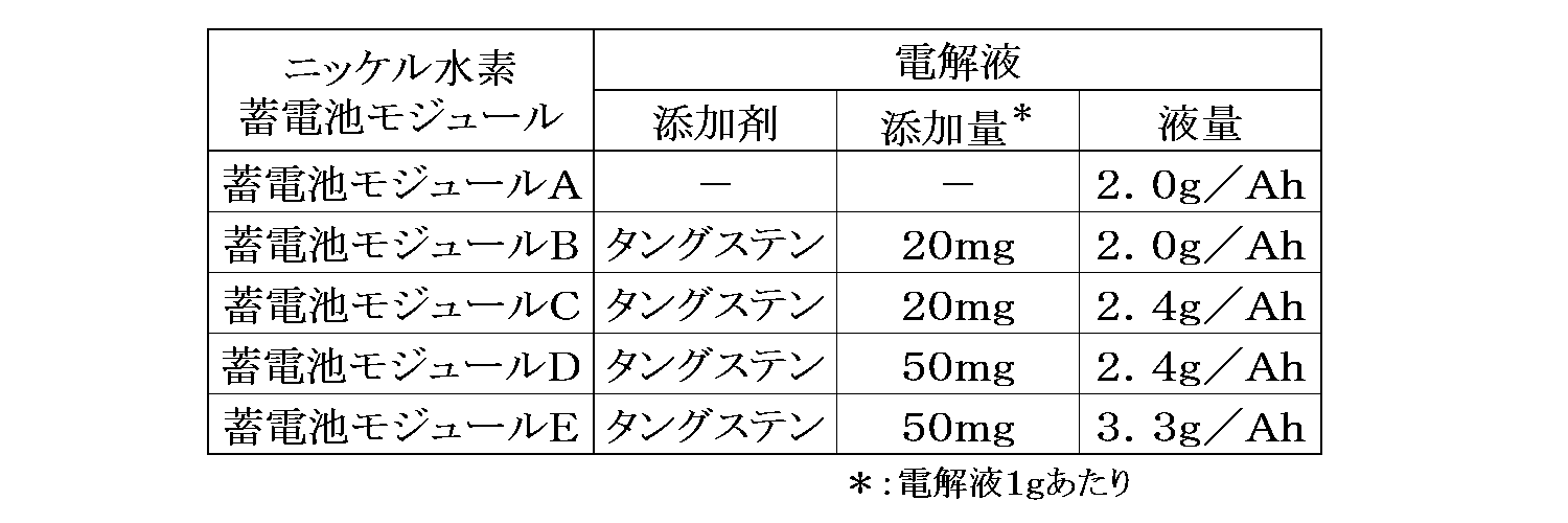
アルカリ電解液は、水酸化カリウム(KOH)、水酸化ナトリウム(NaOH)、水酸化リチウム(LiOH)を所定のモル比となるよう調整した混合水溶液に適宜量のタングステン酸ナトリウムを添加したものを使用した。この場合、表1及び2に示したように、タングステン化合物無添加(蓄電池モジュールA)、タングステン化合物をタングステン換算でアルカリ電解液1gあたり20mg(蓄電池モジュールB及びC)ないし50mg(蓄電池モジュールD及びE)となるよう添加したものを用いた。また、アルカリ電解液量は、それぞれ2.0g/Ah(蓄電池モジュールA及びB)、2.4g/Ah(蓄電池モジュールC及びD)及び3.3g/Ah(蓄電池モジュールE)となるようにした。
上記のようにして作製されたニッケル正極と水素吸蔵合金負極との間に、目付が55g/cm2のポリオレフィン製不織布からなるセパレータを介在させ、巻回して渦巻状電極群を作製した。このとき、前記セパレータの少なくとも一方の面は、スルホン化処理を行うか又はアンモニア吸着能繊維とすることにより、アンモニア吸着能を有している。
この渦巻状電極群の上端面に露出した、ニッケル正極板の極板芯体端部に正極集電体を溶接した。一方、下端面に露出した水素吸蔵合金極板の極板芯体端部に、負極集電体を溶接した。この渦巻状電極体を外装缶に挿入し、負極集電体と缶底とを溶接し、上記電解液を前記外装缶に注液した。この後、集電リードに封口体を溶接し、封口部をカシメて封口し、それぞれ電池容量が6.0Ahの5種類の円筒状ニッケル水素蓄電池を作製した。
上述のようにして作製された5種類の円筒状ニッケル水素蓄電池に共通する具体的構成を図1を用いて説明する。これらのニッケル水素蓄電池10は、上述のようにして作製されたニッケル正極11と、水素吸蔵合金負極12とがセパレータ13とを介して互いに絶縁された状態で巻き回された巻回電極体14を有している。
ニッケル正極11は、ニッケルめっき鋼板からなるパンチングメタルからなる正極芯体15の両面に形成された多孔質ニッケル焼結体16内に、水酸化ニッケルを主成分とし、水酸化亜鉛、水酸化コバルトから選択したいずれかの化合物が添加された正極活物質17が充填された構成を有している。水素吸蔵合金負極12は、ニッケルメッキした軟鋼材製のパンチングメタルからなる負極芯体18の両面に負極活物質としての水素吸蔵合金粉末を有する負極合剤層19が形成されている。
巻回電極体14の下部には負極芯体18に負極集電体20が抵抗溶接されており、巻回電極体14の上部には正極芯体15に正極集電体21が抵抗溶接されている。巻回電極体14は、鉄にニッケルメッキを施した有底円筒形の金属製の外装缶22内に挿入されており、負極集電体20と外装缶22の底部との間はスポット溶接されている。
外装缶22の開放端側には、鉄にニッケルメッキを施した封口体23が、ガスケット24を介して外装缶22とは電気的に絶縁された状態で、カシメ固定されている。正極集電体21は、封口体23に溶接されて電気的に接続されている。正極集電体21の中央部には開口25が設けられており、この開口25には弁体26が開口25を塞ぐように配置されている。
また、封口体23の上面には、開口25の周囲を覆い、かつ、弁体26とは一定距離だけ隔てた状態となるように、正極キャップ27が設けられている。正極キャップ27には、適宜ガス抜き孔(図示省略)が設けられている。正極キャップ27の内面と弁体26との間にはバネ28が設けられており、弁体26はバネ28によって封口体23の開口25を塞ぐように押圧されている。この弁体26は外装缶22の内部の圧力が高くなった際に、内部の圧力を逃がす安全弁としての機能を有している。
上述のようにして作製された5種類の円筒状ニッケル水素蓄電池を、それぞれ25℃に維持された恒温槽中で、1It(=6A)の充電電流でSOC(State Of Charge:充電状態)のが120%まで充電し、1時間休止した。次いで、60℃に維持された恒温槽中で24時間放置した後、30℃に維持された恒温槽中で、1Itの放電電流で電池電圧が0.9Vになるまで放電させた。この充放電サイクルを1サイクルとして2サイクル繰り返して、電池を活性化した。次いで、活性化された5種類の円筒状ニッケル水素蓄電池をそれぞれ10個、直列に接続し、下記表1に示す5種類の蓄電池モジュールA~Eを作製した。
<蓄電池システム>
上記の鉛蓄電池と上記表1に示した5種類の蓄電池モジュールA~Eを用い、それぞれ以下の処理を行ってから並列接続した。
上記の鉛蓄電池と上記表1に示した5種類の蓄電池モジュールA~Eを用い、それぞれ以下の処理を行ってから並列接続した。
鉛蓄電池は、電池工業会規格(SBA S 0101)で定める充電条件、すなわち、0.2It=9.6Aの充電電流で、15分ごとに測定した充電中の端子電圧、又は温度換算した電解液密度が3回連続して一定値を示すまで充電し、室温において24時間放置後の開回路電圧を測定し、初期電圧として求めた。
蓄電池モジュールA~Eは、それぞれ1Itの定電流で電池容量の110%まで充電した後、1Itでの定電流で予め実験的に定めた所定のSOCとなるまで放電し、その状態で室温において24時間放置後の開回路電圧を測定し、初期電圧として求めた。予め実験的に定めた所定のSOCとは、予めニッケル水素蓄電池からなる蓄電池モジュールを室温で24時間放置した後の開回路電圧とSOCとの関係を求めておき、蓄電池モジュールを室温において24時間放置した後の開回路電圧が鉛蓄電池の初期電圧とほぼ等しくなるときのSOCを示す。
<耐久評価>
前記方法により所定開始電圧に調整した鉛蓄電池と蓄電池モジュールA~Eのそれぞれを、それぞれの開回路電圧の差が0.1V以内であることを確認してから、並列に接続し、実験例1~5の蓄電池システムを作製した。
前記方法により所定開始電圧に調整した鉛蓄電池と蓄電池モジュールA~Eのそれぞれを、それぞれの開回路電圧の差が0.1V以内であることを確認してから、並列に接続し、実験例1~5の蓄電池システムを作製した。
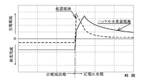
このような鉛蓄電池とニッケル水素蓄電池とが並列に接続された蓄電池システムにおいて、定電流放電から定電圧充電に切り替えた際の一般的な充放電挙動を図2に示した。図2の記載から以下のことが分かる。すなわち、充電時及び放電時とも、充電電流及び放電電流は両方の蓄電池に流れる。しかし、放電時にはニッケル水素蓄電池の放電電流が鉛蓄電池のものよりも大きく、充電時の鉛蓄電池の充電電流は、過度的にニッケル水素蓄電池のものよりも大きくなるが、すぐに低下してニッケル水素蓄電池のものよりも小さくなる
。
。
このことから、鉛蓄電池とニッケル水素蓄電池とが並列に接続された蓄電池システムでは、充放電に際してはサブバッテリであるニッケル水素蓄電池が優先的に充放電を行うため、メインバッテリである鉛蓄電池は放電負荷が低減されて満充電に近い状態が維持され、蓄電池システムの長寿命化が可能となることが分かる。
<耐久試験>
鉛蓄電池単独(参考例)及び実験例1~5のそれぞれの蓄電池システムについて、60℃の恒温槽内で、14Vで60秒の充電と、45Aで59秒の放電と、300Aで1秒の放電とを3600回繰り返した後に、2日間放置する耐久試験を繰り返し行った。
鉛蓄電池単独(参考例)及び実験例1~5のそれぞれの蓄電池システムについて、60℃の恒温槽内で、14Vで60秒の充電と、45Aで59秒の放電と、300Aで1秒の放電とを3600回繰り返した後に、2日間放置する耐久試験を繰り返し行った。
上記のようにして300Aで1秒放電した後の蓄電池システムの電圧が7.2Vを下回ったときの充放電の繰り返し回数を耐久性の指標として測定し、結果を、実験例2の繰り返し回数に対する比率Xとして求めた。結果をまとめて表2に示した。
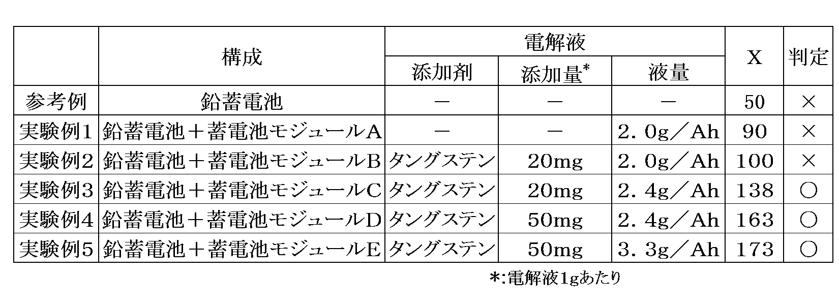
上記結果によれば、蓄電池モジュールAと鉛蓄電池を並列接続した実験例1の場合、鉛蓄電池単独の場合よりも耐久性が向上するが、その効果は十分でなかった。また、蓄電池モジュールBと鉛蓄電池を並列接続した実験例2の場合、電解液にタングステン化合物を添加することで、実験例1の場合に対して耐久性の改善効果が確認された。これは電解液中に充分量のタングステン化合物を添加することで、充放電サイクルに伴う電池温度上昇を抑制することが可能となるためと考えられる。
一般的に、ニッケル水素蓄電池では、充電時に正極から副反応として酸素が発生する。発生した酸素は、水素吸蔵合金である負極中の水素と反応するリコンビ反応によって、水となり電解液へ回収される。このリコンビ反応の発熱量が大きいため、電池温度上昇が促進される。実験例2で電解液にタングステン化合物を添加することで、正極充電効率が改善されるため、充電時の酸素発生量が抑制され、電池温度の上昇を抑制できると考えられる。
蓄電池モジュールC又は蓄電池モジュールDと鉛蓄電池を並列接続した実験例3及び4では、大幅な耐久性の向上が確認された。これは充分量のタングステン化合物が添加され、正極充電効率が改善されるとともに、電解液量を2.4g/Ahと多くすることで、電解液の熱容量が大きくなり、電池温度の上昇を抑制できたものと考えられる。ただし、タングステン化合物の添加量をタングステン換算で50mgよりも多く添加すると、液抵抗の増大により電池出力特性が低下することから、タングステン化合物の添加量は電解液1g当たりタングステン換算で20mg以上、50mg以下が好ましい。
さらに、蓄電池モジュールEと鉛蓄電池を並列接続した実験例5に示されるとおり、電池内に注液される電解液量が多いほど、寿命特性が改善される。しかしながら、電池内に注液される電解液量が3.3g/Ahを超えると、充電時の電池内圧上昇が大きくなり、場合によっては漏液するといった課題が発生するため、電解液量は2.4g/Ah以上、3.3g/Ah以下が好ましい。
なお、蓄電池モジュールB~Eでは、電解液中にタングステン源としてタングステン酸ナトリウムを添加した例を示したが、タングステン酸カリウム、タングステン酸リチウム等のタングステンの水溶性酸素酸塩や、タングステンの酸化物も同様に使用し得る。タングステン以外に、ニオブ化合物ないしモリブデン化合物を添加した場合においても同様の効果が奏される。この場合、ニオブの水溶性酸素酸塩や酸化物、モリブデンの水溶性酸素酸塩や酸化物として添加すればよい。これらのことから、電解液中に、タングステン化合物、モリブデン化合物、ニオブ化合物から選択された少なくとも1種が、電解液1g当たり、タングステン、モリブデンないしニオブ換算で20mg以上、50mg以下で含有されていることが好ましいことが分かる。
また、上記実験例では負極活物質としてLa0.4Nd0.5Mg0.1Ni3.5Al0.2で表される水素吸蔵合金を用いたニッケル水素蓄電池を用いた例を示したが、他の組成の水素吸蔵合金を用いたニッケル水素蓄電池も使用し得る。例えば、負極活物質として一般式がLaxReyMg1-x-yNin-aMa(ReはLaを除く希土類元素から選択される少なくとも1種の元素:Nd、Sm、Y等、MはAl、Znから選択される少なくとも1種の元素)で表される水素吸蔵合金を用いたニッケル水素蓄電池を用いることができる。
上記実験例では鉛蓄電池として公称電圧12Vのものを用いたため、蓄電池モジュールA~Eとしては、ニッケル水素蓄電池を10直列したものを用いた例を示した。ただし、鉛蓄電池は車載用として公称電圧6V(3直列)、12V(6直列)及び24V(12直列)の製品が広く用いられており、個々のニッケル水素蓄電池は公称電圧が1.2Vであるため、ニッケル水素蓄電池が5直列で6V、10直列で12V及び20直列で24Vとなり、容易に鉛蓄電池と同じ公称電圧とし得る。すなわち、用いた鉛蓄電池の公称電圧が6×nV(ただし、nは正の整数)であるとき、この鉛蓄電池に対して5n個のニッケル水素蓄電池を直列接続した蓄電池モジュールを並列に接続すればよい。
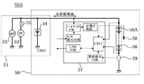
なお、図3に示したように、従来の車載用電源システム部51は、オルタネーター52と、スターター53と、鉛蓄電池54とが、適宜スイッチ55を介して、互いに並列に接続された構成を備えている。スターター53は、最初の始動時ないしアイドルストップ状態からの始動時のスイッチ55がON状態とされた際に、エンジン(図示省略)を駆動させるためのモーターとして作動するものであり、この時の駆動電力は鉛蓄電池54の放電によって供給される。オルタネーター52は、エンジンの駆動時ないしエンジンブレーキとして機能させるための発電機として作動するものであり、この時の回生エネルギーは鉛蓄電池54に充電される。
本発明の一態様に係る蓄電池システム50は、上述した車載用電源システム部51における鉛蓄電池54に対して、サブバッテリとしての蓄電池モジュール56Aを並列に接続したものに対応する。すなわち、オルタネーター52と、スターター53と、鉛蓄電池54及び蓄電池モジュール56Aによって形成される蓄電池システム50とによって、新たな車載用電源システム50Aが構成される。この場合、蓄電池モジュール56Aには、適宜制御回路57、ニッケル水素蓄電池56の温度を測定するためのサーミスタなどの温度測定手段58、蓄電池モジュール56Aに流れる電流を測定するためのシャント抵抗59等が接続される場合もある。
なお、図4には、サブバッテリとしてニッケル水素蓄電池56を10個直列に接続した蓄電池モジュール56Aを用いた例を示したが、5個直列に接続したモジュールを2個直列に接続した蓄電池モジュールを用いてもよい。さらに、より大容量のサブバッテリが必要な場合には、これらのニッケル水素蓄電池を10個直列に接続した蓄電池モジュールや5個直列に接続したモジュールを2個直列に接続した蓄電池モジュールを複数並列に接続したものを用いればよい。
このような蓄電池システム50を用いた車載用電源システム50Aによれば、最初の始動時ないしアイドルストップ状態からの始動時、定常走行時などの場合には、サブバッテリとしての蓄電池モジュール56Aからの放電電流が鉛蓄電池54のものよりも大きくなる。また、回生エネルギーによる充電時には、鉛蓄電池54の充電電流は、過度的に蓄電池モジュール56Aからのものよりも大きくなるが、すぐに低下して蓄電池モジュール56Aのものよりも小さくなる。これにより、鉛蓄電池54と複数個のニッケル水素蓄電池56からなる蓄電池モジュール56Aとが並列に接続された蓄電池システム50では、充放電に際してはサブバッテリである蓄電池モジュール56Aが優先的に充放電を行うため、メインバッテリである鉛蓄電池54は放電負荷が低減され、蓄電池システム50の長寿命化が可能となる。
10…ニッケル水素蓄電池
11…ニッケル正極
12…水素吸蔵合金負極
13…セパレータ
14…巻回電極体
15…正極芯体
16…多孔質ニッケル焼結体
17…正極活物質
18…負極芯体
19…負極合剤層
20…負極集電体
21…正極集電体
22…金属外装缶
23…封口体
24…ガスケット
25…開口
26…弁体
27…正極キャップ
28…バネ
50…蓄電池システム
50A…車載用電源システム
51…従来の車載用電源システム部
52…オルタネーター
53…スターター
54…鉛蓄電池
55…スイッチ
56…ニッケル水素蓄電池
56A…蓄電池モジュール
57…制御回路
58…温度測定手段
59…シャント抵抗
11…ニッケル正極
12…水素吸蔵合金負極
13…セパレータ
14…巻回電極体
15…正極芯体
16…多孔質ニッケル焼結体
17…正極活物質
18…負極芯体
19…負極合剤層
20…負極集電体
21…正極集電体
22…金属外装缶
23…封口体
24…ガスケット
25…開口
26…弁体
27…正極キャップ
28…バネ
50…蓄電池システム
50A…車載用電源システム
51…従来の車載用電源システム部
52…オルタネーター
53…スターター
54…鉛蓄電池
55…スイッチ
56…ニッケル水素蓄電池
56A…蓄電池モジュール
57…制御回路
58…温度測定手段
59…シャント抵抗
Claims (3)
- 水酸化ニッケルを主正極活物質とするニッケル正極と、水素吸蔵合金を負極活物質とする水素吸蔵合金負極と、セパレータと、アルカリ電解液とを備え、
前記アルカリ電解液の量は、単位正極容量当たり、2.4g/Ah以上、3.3g/Ah以下であり、
前記アルカリ電解液中には、タングステン化合物、モリブデン化合物、ニオブ化合物から選択された少なくとも1種がそれぞれの金属換算で前記アルカリ電解液1g当たり、20mg以上、50mg以下で含有されている、ニッケル水素蓄電池。 - 複数個の請求項1に記載のニッケル水素蓄電池と、鉛蓄電池とが並列に接続されている、蓄電池システム。
- 前記蓄電池システムは、車両のエンジンルームに設置されている請求項2に記載の蓄電池システム。
Priority Applications (2)
| Application Number | Priority Date | Filing Date | Title |
|---|---|---|---|
| JP2014544233A JPWO2014068868A1 (ja) | 2012-10-30 | 2013-10-11 | ニッケル水素蓄電池及び蓄電池システム |
| CN201380055122.4A CN104737358A (zh) | 2012-10-30 | 2013-10-11 | 镍氢蓄电池以及蓄电池系统 |
Applications Claiming Priority (2)
| Application Number | Priority Date | Filing Date | Title |
|---|---|---|---|
| JP2012239415 | 2012-10-30 | ||
| JP2012-239415 | 2012-10-30 |
Publications (1)
| Publication Number | Publication Date |
|---|---|
| WO2014068868A1 true WO2014068868A1 (ja) | 2014-05-08 |
Family
ID=50626821
Family Applications (1)
| Application Number | Title | Priority Date | Filing Date |
|---|---|---|---|
| PCT/JP2013/006085 Ceased WO2014068868A1 (ja) | 2012-10-30 | 2013-10-11 | ニッケル水素蓄電池及び蓄電池システム |
Country Status (3)
| Country | Link |
|---|---|
| JP (1) | JPWO2014068868A1 (ja) |
| CN (1) | CN104737358A (ja) |
| WO (1) | WO2014068868A1 (ja) |
Families Citing this family (1)
| Publication number | Priority date | Publication date | Assignee | Title |
|---|---|---|---|---|
| JP7348220B2 (ja) * | 2021-02-25 | 2023-09-20 | プライムアースEvエナジー株式会社 | ニッケル水素蓄電池の製造方法 |
Citations (15)
| Publication number | Priority date | Publication date | Assignee | Title |
|---|---|---|---|---|
| JPS60198066A (ja) * | 1984-03-21 | 1985-10-07 | Matsushita Electric Ind Co Ltd | アルカリ蓄電池 |
| JPS61156639A (ja) * | 1984-12-27 | 1986-07-16 | Matsushita Electric Ind Co Ltd | 密閉形アルカリ蓄電池 |
| JPH0888020A (ja) * | 1994-09-14 | 1996-04-02 | Hitachi Maxell Ltd | 水素化物二次電池 |
| JPH08190931A (ja) * | 1995-01-10 | 1996-07-23 | Hitachi Maxell Ltd | 水素化物二次電池 |
| JPH09283174A (ja) * | 1996-04-18 | 1997-10-31 | Matsushita Electric Ind Co Ltd | アルカリ蓄電池 |
| JPH10172558A (ja) * | 1996-12-09 | 1998-06-26 | Hitachi Maxell Ltd | 水素化物二次電池 |
| JP2000021439A (ja) * | 1998-06-30 | 2000-01-21 | Toshiba Corp | ニッケル水素二次電池 |
| JP2001217000A (ja) * | 1999-02-26 | 2001-08-10 | Toshiba Battery Co Ltd | ニッケル・水素二次電池 |
| JP2003197279A (ja) * | 2001-12-28 | 2003-07-11 | Furukawa Battery Co Ltd:The | シール形蓄電池 |
| JP2004235088A (ja) * | 2003-01-31 | 2004-08-19 | Sanyo Electric Co Ltd | ニッケル水素蓄電池 |
| JP2004281289A (ja) * | 2003-03-18 | 2004-10-07 | Sanyo Electric Co Ltd | アルカリ蓄電池 |
| JP2005108610A (ja) * | 2003-09-30 | 2005-04-21 | Sanyo Electric Co Ltd | アルカリ蓄電池および組電池 |
| JP2012238565A (ja) * | 2011-04-28 | 2012-12-06 | Sanyo Electric Co Ltd | アルカリ蓄電池 |
| JP2013114888A (ja) * | 2011-11-29 | 2013-06-10 | Sanyo Electric Co Ltd | アルカリ蓄電及びこのアルカリ蓄電池を用いたアルカリ蓄電池システム |
| JP2013178883A (ja) * | 2012-02-28 | 2013-09-09 | Sanyo Electric Co Ltd | アルカリ蓄電池及びアルカリ蓄電池システム |
Family Cites Families (10)
| Publication number | Priority date | Publication date | Assignee | Title |
|---|---|---|---|---|
| JP2962326B1 (ja) * | 1997-12-26 | 1999-10-12 | 松下電器産業株式会社 | バックアップ電源用ニッケル−水素蓄電池 |
| JP4757369B2 (ja) * | 2000-05-08 | 2011-08-24 | パナソニック株式会社 | 角形アルカリ蓄電池、並びにこれを用いた単位電池及び組電池 |
| US6577099B2 (en) * | 2001-05-04 | 2003-06-10 | Delphi Technologies, Inc. | Method and apparatus for providing and storing power in a vehicle |
| JP2003249222A (ja) * | 2001-12-12 | 2003-09-05 | Sanyo Electric Co Ltd | ニッケル・水素蓄電池 |
| JP4639620B2 (ja) * | 2004-03-29 | 2011-02-23 | トヨタ自動車株式会社 | アルカリ蓄電池 |
| CN1790777A (zh) * | 2004-12-17 | 2006-06-21 | 比亚迪股份有限公司 | 一种镍-氢电池负极和采用该负极的电池及它们的制备方法 |
| CN101369672A (zh) * | 2008-10-07 | 2009-02-18 | 湖南科力远新能源股份有限公司 | 一种碱性镍氢电池专用电解液 |
| CN101826644A (zh) * | 2010-02-11 | 2010-09-08 | 中国科学院上海微系统与信息技术研究所 | 一种长寿命铅酸蓄电池系统和使用方法 |
| JP5488046B2 (ja) * | 2010-02-25 | 2014-05-14 | 株式会社デンソー | 車載電源装置 |
| CN101950818A (zh) * | 2010-09-20 | 2011-01-19 | 四川宝生新能源电池有限公司 | 高温镍氢电池 |
-
2013
- 2013-10-11 CN CN201380055122.4A patent/CN104737358A/zh active Pending
- 2013-10-11 WO PCT/JP2013/006085 patent/WO2014068868A1/ja not_active Ceased
- 2013-10-11 JP JP2014544233A patent/JPWO2014068868A1/ja active Pending
Patent Citations (15)
| Publication number | Priority date | Publication date | Assignee | Title |
|---|---|---|---|---|
| JPS60198066A (ja) * | 1984-03-21 | 1985-10-07 | Matsushita Electric Ind Co Ltd | アルカリ蓄電池 |
| JPS61156639A (ja) * | 1984-12-27 | 1986-07-16 | Matsushita Electric Ind Co Ltd | 密閉形アルカリ蓄電池 |
| JPH0888020A (ja) * | 1994-09-14 | 1996-04-02 | Hitachi Maxell Ltd | 水素化物二次電池 |
| JPH08190931A (ja) * | 1995-01-10 | 1996-07-23 | Hitachi Maxell Ltd | 水素化物二次電池 |
| JPH09283174A (ja) * | 1996-04-18 | 1997-10-31 | Matsushita Electric Ind Co Ltd | アルカリ蓄電池 |
| JPH10172558A (ja) * | 1996-12-09 | 1998-06-26 | Hitachi Maxell Ltd | 水素化物二次電池 |
| JP2000021439A (ja) * | 1998-06-30 | 2000-01-21 | Toshiba Corp | ニッケル水素二次電池 |
| JP2001217000A (ja) * | 1999-02-26 | 2001-08-10 | Toshiba Battery Co Ltd | ニッケル・水素二次電池 |
| JP2003197279A (ja) * | 2001-12-28 | 2003-07-11 | Furukawa Battery Co Ltd:The | シール形蓄電池 |
| JP2004235088A (ja) * | 2003-01-31 | 2004-08-19 | Sanyo Electric Co Ltd | ニッケル水素蓄電池 |
| JP2004281289A (ja) * | 2003-03-18 | 2004-10-07 | Sanyo Electric Co Ltd | アルカリ蓄電池 |
| JP2005108610A (ja) * | 2003-09-30 | 2005-04-21 | Sanyo Electric Co Ltd | アルカリ蓄電池および組電池 |
| JP2012238565A (ja) * | 2011-04-28 | 2012-12-06 | Sanyo Electric Co Ltd | アルカリ蓄電池 |
| JP2013114888A (ja) * | 2011-11-29 | 2013-06-10 | Sanyo Electric Co Ltd | アルカリ蓄電及びこのアルカリ蓄電池を用いたアルカリ蓄電池システム |
| JP2013178883A (ja) * | 2012-02-28 | 2013-09-09 | Sanyo Electric Co Ltd | アルカリ蓄電池及びアルカリ蓄電池システム |
Also Published As
| Publication number | Publication date |
|---|---|
| CN104737358A (zh) | 2015-06-24 |
| JPWO2014068868A1 (ja) | 2016-09-08 |
Similar Documents
| Publication | Publication Date | Title |
|---|---|---|
| JP5196938B2 (ja) | アルカリ蓄電池システム | |
| US20090087745A1 (en) | Alkaline storage battery system | |
| US20120052353A1 (en) | Cylindrical nickel-hydrogen storage battery | |
| JP2013114888A (ja) | アルカリ蓄電及びこのアルカリ蓄電池を用いたアルカリ蓄電池システム | |
| JP6225116B2 (ja) | 蓄電池システム | |
| JP5849768B2 (ja) | アルカリ蓄電池及びアルカリ蓄電池システム | |
| JP5853799B2 (ja) | アルカリ蓄電池 | |
| US20050019657A1 (en) | Nickel-hydrogen cell | |
| JP5717125B2 (ja) | アルカリ蓄電池 | |
| JP6105389B2 (ja) | アルカリ蓄電池 | |
| JP6200897B2 (ja) | 蓄電池モジュール及び蓄電池システム | |
| WO2014068866A1 (ja) | 蓄電池モジュールを搭載した車両 | |
| JPWO2014068868A1 (ja) | ニッケル水素蓄電池及び蓄電池システム | |
| WO2014068954A1 (ja) | 蓄電池システム | |
| JP2013134903A (ja) | アルカリ蓄電池用水素吸蔵合金及びこれを用いたアルカリ蓄電池 | |
| JPWO2014050075A1 (ja) | 蓄電池システム。 | |
| JP2013134904A (ja) | アルカリ蓄電池およびこれを用いたアルカリ蓄電池システム | |
| JP5105766B2 (ja) | アルカリ蓄電池およびその製造方法ならびに組電池装置 | |
| JP2015028845A (ja) | アルカリ蓄電池及びアルカリ蓄電池システム | |
| JP3895984B2 (ja) | ニッケル・水素蓄電池 | |
| JP5334498B2 (ja) | アルカリ蓄電池 | |
| CN115411265B (zh) | 储氢合金负极以及包含储氢合金负极的镍氢二次电池 | |
| JP5752487B2 (ja) | アルカリ蓄電池およびアルカリ蓄電池システム | |
| JP2013178882A (ja) | アルカリ蓄電池 | |
| JP2015043285A (ja) | アルカリ蓄電池 |
Legal Events
| Date | Code | Title | Description |
|---|---|---|---|
| 121 | Ep: the epo has been informed by wipo that ep was designated in this application |
Ref document number: 13851145 Country of ref document: EP Kind code of ref document: A1 |
|
| ENP | Entry into the national phase |
Ref document number: 2014544233 Country of ref document: JP Kind code of ref document: A |
|
| NENP | Non-entry into the national phase |
Ref country code: DE |
|
| 122 | Ep: pct application non-entry in european phase |
Ref document number: 13851145 Country of ref document: EP Kind code of ref document: A1 |