WO2014065022A1 - エンジン室の換気構造 - Google Patents
エンジン室の換気構造 Download PDFInfo
- Publication number
- WO2014065022A1 WO2014065022A1 PCT/JP2013/073942 JP2013073942W WO2014065022A1 WO 2014065022 A1 WO2014065022 A1 WO 2014065022A1 JP 2013073942 W JP2013073942 W JP 2013073942W WO 2014065022 A1 WO2014065022 A1 WO 2014065022A1
- Authority
- WO
- WIPO (PCT)
- Prior art keywords
- engine
- ventilation duct
- engine room
- cooling fan
- heat exchanger
- Prior art date
- Legal status (The legal status is an assumption and is not a legal conclusion. Google has not performed a legal analysis and makes no representation as to the accuracy of the status listed.)
- Ceased
Links
Images


Classifications
-
- F—MECHANICAL ENGINEERING; LIGHTING; HEATING; WEAPONS; BLASTING
- F01—MACHINES OR ENGINES IN GENERAL; ENGINE PLANTS IN GENERAL; STEAM ENGINES
- F01P—COOLING OF MACHINES OR ENGINES IN GENERAL; COOLING OF INTERNAL-COMBUSTION ENGINES
- F01P11/00—Component parts, details, or accessories not provided for in, or of interest apart from, groups F01P1/00 - F01P9/00
- F01P11/10—Guiding or ducting cooling-air, to, or from, liquid-to-air heat exchangers
-
- B—PERFORMING OPERATIONS; TRANSPORTING
- B60—VEHICLES IN GENERAL
- B60K—ARRANGEMENT OR MOUNTING OF PROPULSION UNITS OR OF TRANSMISSIONS IN VEHICLES; ARRANGEMENT OR MOUNTING OF PLURAL DIVERSE PRIME-MOVERS IN VEHICLES; AUXILIARY DRIVES FOR VEHICLES; INSTRUMENTATION OR DASHBOARDS FOR VEHICLES; ARRANGEMENTS IN CONNECTION WITH COOLING, AIR INTAKE, GAS EXHAUST OR FUEL SUPPLY OF PROPULSION UNITS IN VEHICLES
- B60K11/00—Arrangement in connection with cooling of propulsion units
- B60K11/02—Arrangement in connection with cooling of propulsion units with liquid cooling
- B60K11/04—Arrangement or mounting of radiators, radiator shutters, or radiator blinds
-
- B—PERFORMING OPERATIONS; TRANSPORTING
- B60—VEHICLES IN GENERAL
- B60K—ARRANGEMENT OR MOUNTING OF PROPULSION UNITS OR OF TRANSMISSIONS IN VEHICLES; ARRANGEMENT OR MOUNTING OF PLURAL DIVERSE PRIME-MOVERS IN VEHICLES; AUXILIARY DRIVES FOR VEHICLES; INSTRUMENTATION OR DASHBOARDS FOR VEHICLES; ARRANGEMENTS IN CONNECTION WITH COOLING, AIR INTAKE, GAS EXHAUST OR FUEL SUPPLY OF PROPULSION UNITS IN VEHICLES
- B60K11/00—Arrangement in connection with cooling of propulsion units
- B60K11/06—Arrangement in connection with cooling of propulsion units with air cooling
-
- B—PERFORMING OPERATIONS; TRANSPORTING
- B62—LAND VEHICLES FOR TRAVELLING OTHERWISE THAN ON RAILS
- B62D—MOTOR VEHICLES; TRAILERS
- B62D25/00—Superstructure or monocoque structure sub-units; Parts or details thereof not otherwise provided for
- B62D25/08—Front or rear portions
- B62D25/10—Bonnets or lids, e.g. for trucks, tractors, busses, work vehicles
-
- E—FIXED CONSTRUCTIONS
- E02—HYDRAULIC ENGINEERING; FOUNDATIONS; SOIL SHIFTING
- E02F—DREDGING; SOIL-SHIFTING
- E02F9/00—Component parts of dredgers or soil-shifting machines, not restricted to one of the kinds covered by groups E02F3/00 - E02F7/00
- E02F9/08—Superstructures; Supports for superstructures
- E02F9/0833—Improving access, e.g. for maintenance, steps for improving driver's access, handrails
-
- E—FIXED CONSTRUCTIONS
- E02—HYDRAULIC ENGINEERING; FOUNDATIONS; SOIL SHIFTING
- E02F—DREDGING; SOIL-SHIFTING
- E02F9/00—Component parts of dredgers or soil-shifting machines, not restricted to one of the kinds covered by groups E02F3/00 - E02F7/00
- E02F9/08—Superstructures; Supports for superstructures
- E02F9/0858—Arrangement of component parts installed on superstructures not otherwise provided for, e.g. electric components, fenders, air-conditioning units
- E02F9/0866—Engine compartment, e.g. heat exchangers, exhaust filters, cooling devices, silencers, mufflers, position of hydraulic pumps in the engine compartment
-
- E—FIXED CONSTRUCTIONS
- E02—HYDRAULIC ENGINEERING; FOUNDATIONS; SOIL SHIFTING
- E02F—DREDGING; SOIL-SHIFTING
- E02F9/00—Component parts of dredgers or soil-shifting machines, not restricted to one of the kinds covered by groups E02F3/00 - E02F7/00
- E02F9/08—Superstructures; Supports for superstructures
- E02F9/0858—Arrangement of component parts installed on superstructures not otherwise provided for, e.g. electric components, fenders, air-conditioning units
- E02F9/0891—Lids or bonnets or doors or details thereof
-
- F—MECHANICAL ENGINEERING; LIGHTING; HEATING; WEAPONS; BLASTING
- F01—MACHINES OR ENGINES IN GENERAL; ENGINE PLANTS IN GENERAL; STEAM ENGINES
- F01N—GAS-FLOW SILENCERS OR EXHAUST APPARATUS FOR MACHINES OR ENGINES IN GENERAL; GAS-FLOW SILENCERS OR EXHAUST APPARATUS FOR INTERNAL-COMBUSTION ENGINES
- F01N3/00—Exhaust or silencing apparatus having means for purifying, rendering innocuous, or otherwise treating exhaust
- F01N3/08—Exhaust or silencing apparatus having means for purifying, rendering innocuous, or otherwise treating exhaust for rendering innocuous
- F01N3/10—Exhaust or silencing apparatus having means for purifying, rendering innocuous, or otherwise treating exhaust for rendering innocuous by thermal or catalytic conversion of noxious components of exhaust
- F01N3/18—Exhaust or silencing apparatus having means for purifying, rendering innocuous, or otherwise treating exhaust for rendering innocuous by thermal or catalytic conversion of noxious components of exhaust characterised by methods of operation; Control
- F01N3/20—Exhaust or silencing apparatus having means for purifying, rendering innocuous, or otherwise treating exhaust for rendering innocuous by thermal or catalytic conversion of noxious components of exhaust characterised by methods of operation; Control specially adapted for catalytic conversion
- F01N3/206—Adding periodically or continuously substances to exhaust gases for promoting purification, e.g. catalytic material in liquid form, NOx reducing agents
- F01N3/2066—Selective catalytic reduction [SCR]
-
- B—PERFORMING OPERATIONS; TRANSPORTING
- B60—VEHICLES IN GENERAL
- B60Y—INDEXING SCHEME RELATING TO ASPECTS CROSS-CUTTING VEHICLE TECHNOLOGY
- B60Y2200/00—Type of vehicle
- B60Y2200/40—Special vehicles
- B60Y2200/41—Construction vehicles, e.g. graders, excavators
-
- F—MECHANICAL ENGINEERING; LIGHTING; HEATING; WEAPONS; BLASTING
- F01—MACHINES OR ENGINES IN GENERAL; ENGINE PLANTS IN GENERAL; STEAM ENGINES
- F01N—GAS-FLOW SILENCERS OR EXHAUST APPARATUS FOR MACHINES OR ENGINES IN GENERAL; GAS-FLOW SILENCERS OR EXHAUST APPARATUS FOR INTERNAL-COMBUSTION ENGINES
- F01N2590/00—Exhaust or silencing apparatus adapted to particular use, e.g. for military applications, airplanes, submarines
- F01N2590/08—Exhaust or silencing apparatus adapted to particular use, e.g. for military applications, airplanes, submarines for heavy duty applications, e.g. trucks, buses, tractors, locomotives
-
- F—MECHANICAL ENGINEERING; LIGHTING; HEATING; WEAPONS; BLASTING
- F01—MACHINES OR ENGINES IN GENERAL; ENGINE PLANTS IN GENERAL; STEAM ENGINES
- F01N—GAS-FLOW SILENCERS OR EXHAUST APPARATUS FOR MACHINES OR ENGINES IN GENERAL; GAS-FLOW SILENCERS OR EXHAUST APPARATUS FOR INTERNAL-COMBUSTION ENGINES
- F01N2610/00—Adding substances to exhaust gases
- F01N2610/02—Adding substances to exhaust gases the substance being ammonia or urea
-
- F—MECHANICAL ENGINEERING; LIGHTING; HEATING; WEAPONS; BLASTING
- F01—MACHINES OR ENGINES IN GENERAL; ENGINE PLANTS IN GENERAL; STEAM ENGINES
- F01N—GAS-FLOW SILENCERS OR EXHAUST APPARATUS FOR MACHINES OR ENGINES IN GENERAL; GAS-FLOW SILENCERS OR EXHAUST APPARATUS FOR INTERNAL-COMBUSTION ENGINES
- F01N2610/00—Adding substances to exhaust gases
- F01N2610/11—Adding substances to exhaust gases the substance or part of the dosing system being cooled
-
- F—MECHANICAL ENGINEERING; LIGHTING; HEATING; WEAPONS; BLASTING
- F01—MACHINES OR ENGINES IN GENERAL; ENGINE PLANTS IN GENERAL; STEAM ENGINES
- F01P—COOLING OF MACHINES OR ENGINES IN GENERAL; COOLING OF INTERNAL-COMBUSTION ENGINES
- F01P1/00—Air cooling
- F01P2001/005—Cooling engine rooms
-
- Y—GENERAL TAGGING OF NEW TECHNOLOGICAL DEVELOPMENTS; GENERAL TAGGING OF CROSS-SECTIONAL TECHNOLOGIES SPANNING OVER SEVERAL SECTIONS OF THE IPC; TECHNICAL SUBJECTS COVERED BY FORMER USPC CROSS-REFERENCE ART COLLECTIONS [XRACs] AND DIGESTS
- Y02—TECHNOLOGIES OR APPLICATIONS FOR MITIGATION OR ADAPTATION AGAINST CLIMATE CHANGE
- Y02A—TECHNOLOGIES FOR ADAPTATION TO CLIMATE CHANGE
- Y02A50/00—TECHNOLOGIES FOR ADAPTATION TO CLIMATE CHANGE in human health protection, e.g. against extreme weather
- Y02A50/20—Air quality improvement or preservation, e.g. vehicle emission control or emission reduction by using catalytic converters
-
- Y—GENERAL TAGGING OF NEW TECHNOLOGICAL DEVELOPMENTS; GENERAL TAGGING OF CROSS-SECTIONAL TECHNOLOGIES SPANNING OVER SEVERAL SECTIONS OF THE IPC; TECHNICAL SUBJECTS COVERED BY FORMER USPC CROSS-REFERENCE ART COLLECTIONS [XRACs] AND DIGESTS
- Y02—TECHNOLOGIES OR APPLICATIONS FOR MITIGATION OR ADAPTATION AGAINST CLIMATE CHANGE
- Y02T—CLIMATE CHANGE MITIGATION TECHNOLOGIES RELATED TO TRANSPORTATION
- Y02T10/00—Road transport of goods or passengers
- Y02T10/10—Internal combustion engine [ICE] based vehicles
- Y02T10/12—Improving ICE efficiencies
Definitions
- the present invention relates to an improvement in the ventilation structure of the engine room.
- PM Particulate Matter
- DPF Diesel Particulate Filter
- Patent Documents 1 and 2 propose ventilation structures that can ventilate the engine room using a cooling fan in the heat exchanger room.
- the engine chamber and the fan shroud in which the cooling fan is accommodated communicate with each other through a hose, and the air in the engine chamber is sucked out by the rotation of the cooling fan.
- the engine room can be ventilated and the temperature rise of the engine room can be suppressed.
- a cooling air intake port having a large opening area is provided in the engine room, and a large amount of cooling air is not sucked in to suppress the temperature rise, so that sound loss to the surroundings can be suppressed.
- Patent Documents 1 and 2 the engine room and the fan shroud are communicated with each other using a hose for ventilation, and it is necessary to incorporate the hose. There is a problem with maintainability.
- An object of the present invention is to provide a ventilation structure for an engine room that can satisfactorily ventilate the engine room and improve assembly and maintenance.
- An engine room ventilation structure is the engine room ventilation structure in which an engine is housed and a cooling fan for supplying cooling air to a heat exchanger is adjacent to the engine room, and covers the engine and the cooling fan.
- the ventilation duct has an air passage formed by an inner surface of the exterior cover and a reinforcing member attached to the inner surface.
- the engine room ventilation structure includes a heat exchanger chamber in which the heat exchanger is accommodated, and a partition wall that partitions the heat exchanger chamber and the engine chamber.
- the engine room is provided with an exhaust gas aftertreatment device for purifying exhaust gas from the engine, and one end of the ventilation duct is connected to the exhaust gas aftertreatment device. It is characterized by opening toward.
- the cross-sectional area of the air passage of the ventilation duct gradually decreases from the one end side toward the other end side.
- the cooling fan is rotationally driven in a fan shroud covering the outer periphery thereof, and the fan shroud is accommodated in a frame surrounding the outer periphery, and the other end of the ventilation duct Is characterized in that it communicates with the outer peripheral side of the cooling fan through a communication opening provided in the frame and the fan shroud.
- the ventilation duct is formed using the inner surface of the exterior cover that covers the engine room and the cooling fan side. Therefore, the ventilation duct can be built in the exterior cover in advance when the exterior cover is manufactured. it can. Therefore, it is not necessary to use a hose as in the prior art, and it is possible to save the trouble of assembling the hose, and there is no fear of hindering maintenance. And the engine room can be ventilated satisfactorily by opening the suction side end of the ventilation duct into the engine room.
- the air passage of the ventilation duct is formed by the reinforcing member attached to the inner surface of the exterior case.
- a reinforcing member is used for improving the rigidity of the exterior case and the like. It is a member used regardless of necessity. For this reason, it is not necessary to prepare a special member in order to form the ventilation duct, the exterior cover itself can be easily manufactured, and the manufacturing cost can be reduced.
- the cooling air supplied to the heat exchanger by the cooling fan hardly flows into the engine chamber, and the temperature of the engine chamber is Although it rises more easily, even in such a case, the temperature rise of the engine compartment can be suppressed by performing ventilation through the ventilation duct.
- the temperature of the engine compartment rises further.
- the temperature rise of the engine compartment can be reliably suppressed and more remarkable. An effect can be obtained.
- the cross-sectional area of the air passage of the ventilation duct is gradually reduced toward the cooling fan, the flow velocity of the air flowing through the ventilation duct is gradually increased in the ventilation duct, The suction capability by the negative pressure generated by rotation can be improved.
- the other end of the ventilation duct extends to the outer periphery of the cooling fan and does not directly open, but the fan shroud normally used for covering the cooling fan, the frame for supporting the fan, etc.
- a negative pressure can be applied to the other end of the ventilation duct through the communication openings.
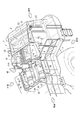
- the disassembled perspective view which shows a part of work vehicle provided with the ventilation structure of the engine room which concerns on one Embodiment of this invention.
- the perspective view which shows the ventilation structure of the said engine compartment.
- the perspective view which shows the principal part of the ventilation structure of the said engine compartment from diagonally downward.
- the perspective view which shows the principal part of the ventilation structure of the said engine compartment.
- the perspective view which shows the cooling structure of urea aqueous solution piping of the said working vehicle.
- the cross-sectional perspective view which shows the principal part of the cooling structure of the said urea aqueous solution piping.
- FIG. 1 is an exploded perspective view showing a part of a work vehicle 1 having a cooling structure for an engine compartment 4 according to the present embodiment.
- a work vehicle 1 is configured as a wheel loader that includes a front frame (not shown) and a rear frame 2 that is articulated to the front frame. Therefore, the front frame of the work vehicle 1 is provided with a work machine including a boom, a bell crank, a bucket, and a hydraulic actuator that drives them.
- a working machine since it is not a structure directly related to this invention, those illustration and description here are abbreviate
- an engine room 4 and a heat exchanger room 5 covered with an exterior cover 3 are arranged side by side on the rear side of a cab (not shown).
- a space between the engine chamber 4 and the heat exchanger chamber 5 is partitioned by a first partition wall 6 as a partition wall.
- the first partition wall 6 partitions the engine chamber 4 and the heat exchanger chamber 5 from above and below, and the outer periphery of the first partition wall 6 is close to or in contact with the inner surface of the exterior cover 3.
- the exterior cover 3 is attached via a support frame or the like standing on the rear frame 2.
- the outer cover 3 includes left and right side covers 31 and 31 that form the side walls across the engine chamber 4 and the heat exchanger chamber 5, a front cover 32 that forms the front side wall of the engine chamber 4, and heat exchange.
- a rear grill (not shown) that is attached to a frame-like frame 56 (see FIG. 4) at the rear of the chamber 5 so as to be openable and closable, and a hood 33 that forms a ceiling portion across the engine chamber 4 and the heat exchanger chamber 5.
- the side cover 31 further includes a front first side cover 34 and a rear second side cover 35 with the first partition wall 6 as a boundary.
- the bonnet 33 includes a first upper cover 36 that covers the upper front part of the engine chamber 4, a second upper cover 37 that covers the upper rear part, and a third upper cover 38 that covers the upper part of the entire heat exchanger chamber 5.
- the first to third upper covers 36 to 38 are detachably attached to the side cover 31 and the front cover 32 by appropriate fastening means such as bolts.
- an engine (not shown) mounted on the rear frame 2, an exhaust turbocharger 41 mounted on the engine, an EGR device, an exhaust gas aftertreatment device 42, and their piping and other supplements are provided. Machines are housed.
- Such an engine compartment 4 is partitioned forward and backward by a second partition wall 7 above the engine. That is, the left and right side edges of the second partition wall 7 are close to or in contact with the vertical surface of the ventilation duct 8 to be described later, and the upper edge is close to or in contact with the lower surface of the second upper cover 37, thereby causing the engine compartment 4 to move forward and backward.
- the lower end of the second partition wall 7 does not reach the left and right sides of the engine, and the engine room 4 communicates with the front and rear under the second partition wall 7.
- An exhaust gas aftertreatment device 42 is disposed in the space on the front side of the second partition wall 7, and other devices including the exhaust turbocharger 41 are disposed in the space on the rear side of the second partition wall 7. Has been placed.
- radiator 51 As a heat exchanger for cooling the engine coolant and an after-heater as another heat exchanger for cooling the intake air (supply air) supercharged by the exhaust turbocharger 41.
- a condenser for an air conditioner installed in the cab can be provided in the heat exchanger chamber 5.
- a rectangular frame-shaped plate 55 is provided in plan view, and the third upper cover 38 is attached above the frame-shaped plate 55. Further, the piping of the radiator 51 and the aftercooler 52 is routed between the engine compartment 4 through the first partition wall 6. As with the rear grill, the cooling fan 54 can be rotated rearward together with the frame that supports it. By rotating the cooling fan 54 away from the heat radiating surface of the radiator 51, maintenance for clogging of the radiator 51 and the like can be performed.
- the outside air passes through the air inlet 39 provided in the side cover 31 and the third upper cover 38 and the gap provided in the lower rear frame 2, and the outside air serves as cooling air in the heat exchanger chamber. 5 flows in.
- the inflowing cooling air passes through the aftercooler 52 and the radiator 51 to cool the intake air and the engine cooling water, and then is discharged from the rear grill through the cooling fan 54.
- the driving of the cooling fan 54 causes the air in the engine room 4 to be actively sucked to the cooling fan 54 side through the ventilation duct 8 constituting the ventilation structure of the present invention, and is discharged from the rear grill through the cooling fan 54. While the air in the engine room 4 continues to be sucked, outside air flows into the engine room 4 as fresh air for ventilation through the gap in the lower rear frame 2 and is sucked through the ventilation duct 8. This is repeated and the engine room 4 is ventilated.
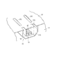
- FIG. 2 is a perspective view showing the ventilation structure of the engine compartment 4, and FIG. 2 also shows a cooling structure of the urea aqueous solution pipe 47 connected to the exhaust gas aftertreatment device 42.
- the exhaust gas aftertreatment device 42 is disposed between a pair of DPF (diesel particulate filter) devices 43 and 43 disposed on the left and right sides and a pair of DPF devices 43 and 43 on the front side of the engine chamber 4.
- SCR (selective reduction catalyst) devices 44, 44 arranged side by side.
- the exhaust pipe connected to the turbine outlet of the exhaust turbocharger 41 wraps around the side of the engine chamber 4, and the tip of the exhaust pipe extends to the vicinity of the front of the engine and is bifurcated.
- One of the branched exhaust pipes is connected to the front portion of the DPF device 43 disposed on the left side of the engine chamber 4, and the exhaust gas flows into the DPF device 43 from here.
- the inflowing exhaust gas flows backward in the cylindrical DPF device 43 along the longitudinal direction of the vehicle, and particulate matter is collected by an internal filter, and thereafter, the mixing pipe 45 connected to the rear part. Flows in.
- the mixing pipe 45 is extended to the front side, and the tip thereof is connected to the front part of the left SCR device 44. That is, the exhaust gas flows forward in the mixing pipe 45.
- an injector for injecting an aqueous urea solution is attached to the base end side (DPF device 43 side) of the mixing pipe 45.
- the urea aqueous solution injected from the injector into the mixing pipe 45 is thermally decomposed into ammonia by the heat of the exhaust gas, and this ammonia flows into the SCR device 44 together with the exhaust gas.
- Exhaust gas and ammonia flowing into the SCR device 44 flow backward in the cylindrical SCR device 44 along the longitudinal direction of the vehicle, and are supplied to the reduction catalyst in the SCR device 44 to oxidize nitrogen in the exhaust gas. Purify things.
- the exhaust gas from which nitrogen oxides have been purified is exhausted to the outside through a tail pipe 46 connected to the rear part of the SCR device 44.
- the other exhaust pipe branched is routed to the right side of the engine through the front side of the engine and connected to the front part of the DPF device 43 arranged on the right side.
- the subsequent flow and post-processing of the exhaust gas flowing into the DPF device 43 are the same as those on the left side, and can be understood from the above description, so the description thereof is omitted here.
- a pair of SCR devices 44, 44 are disposed in the upper center of the engine, and the pair of DPF devices 43, 43 are disposed at the left and right shoulder portions of the engine. It is disposed at a position one step lower than 44. Therefore, the side cover 31 shown in FIG. 1 is provided with an inclined surface 31A that is inclined downward from the center side of the vehicle toward the left and right sides in accordance with the arrangement positions of the DPF device 43 and the SCR device 44. ing. By providing the inclined surface 31A, visibility to the left and right sides of the rear portion of the vehicle from the cab is improved.
- a ventilation duct 8 is provided inside the left and right side covers 31 from the middle of the engine room 4 to the rear part of the heat exchanger room 5.
- the inclined surface 31A described above is provided on the upper side of the side cover 31 in the front-rear direction, and a reinforcing member 81 is attached to the inner surface of the side cover 31 substantially corresponding to the inclined surface 31A.
- the reinforcing member 81 is illustrated in a solid line, and is drawn in a state where it is removed from the side cover 31 for convenience.
- the reinforcing member 81 is attached for the purpose of improving the rigidity of the side cover 31.
- the reinforcing member 81 is provided on the first side cover 34 and provided on the second side cover 35 and the first reinforcing member 82 located in the engine compartment 4.
- a second reinforcing member 83 on the rear side located in the heat exchanger chamber 5.
- Each of the first and second reinforcing members 82 and 83 has an L-shaped cross section.
- the ventilation duct 8 is formed using the inner surface of the reinforcing member 81 (the surface facing the side cover 31) and the inner surface of the side cover 31, and the internal space functions as an air passage for the ventilation duct 8.
- the first and second reinforcing members 82 and 83 are partitioned by an installation frame 61 (see also FIGS. 3 and 4) installed between the left and right second side covers 31 (second reinforcing members 83). Therefore, the ventilation duct 8 is partitioned by the end portion of the installation frame 61 in the middle of the front-rear direction.
- the communication portion 62 is provided in the partition portion, and the space between the first and second reinforcing members 82 and 83 is provided. Air circulation is ensured.
- Such an installation frame 61 is provided corresponding to the upper part of the first partition wall 6, and the front side frame portion of the frame-like plate 55 is supported by the upper surface thereof.
- the front end of the ventilation duct 8 is located in the vicinity of the second partition wall 7 of the engine room 4 and opens toward the exhaust gas aftertreatment device 42 disposed on the front side of the second partition wall 7.
- air heated by the heat of the exhaust gas aftertreatment device 42 is actively sucked. Further, the air heated by the engine and the exhaust turbocharger 41 is sucked into the ventilation duct 8 from below the second partition wall 7 from the space behind the second partition wall 7.
- the ventilation duct 8 has a so-called tapered shape in which the cross-sectional area of the air passage gradually decreases from the front end toward the rear end. For this reason, at the rear end where the cross-sectional area is reduced, the negative pressure generated by the rotation of the cooling fan 54 can be applied satisfactorily, and a pressure gradient can be formed in a long region extending in the front-rear direction of the ventilation duct 8. It is possible to reliably suck the air 4 backward.
- FIG. 3 is a perspective view of the exterior cover 3 provided with the ventilation structure of the present invention as viewed from below.
- FIG. 4 is a perspective view of the main part of the ventilation structure as viewed from the rear. 3, illustration of the 1st partition wall 6 and the 2nd partition wall 7 is abbreviate
- a portal frame 56 as a frame standing on the rear frame 2 (FIGS. 1 and 2) is attached to the rear end of the exterior cover 3.
- the portal frame 56 includes a pair of left and right vertical frames 57 and 57 attached to a vertical rear edge portion of the second side cover 35, a horizontal frame 58 spanned between the upper ends of the vertical frames 57 and 57, and a horizontal frame 58. And an intermediate frame 59 that spans between the vertical frames 57 and 57.
- the vertical frame 57 has an L-shaped cross section and is erected so that the corner portion faces the inward side of the vehicle.
- each piece forming an L-shape is provided with a communication opening 57A.
- the portion provided with the communication opening 57A is covered with upper and lower ribs and a cover 57B welded from the side.
- the horizontal frame 58 is made of a channel material having a concave cross section, and is installed with the opening portion facing upward.
- the horizontal frame 58 functions as an air passage in the left-right direction by the upper opening portion being covered with the third upper cover 38.
- a plurality of communication openings 58A are provided on the bottom surface of the horizontal frame 58 along the longitudinal direction thereof. Further, on both sides in the longitudinal direction of the horizontal frame 58, cutout portions 58B are formed by cutting out the front web portion.
- the rear end of the second reinforcing member 83 constituting the reinforcing member 81 is connected to the notch 58B, and the ventilation duct 8 communicates with the air passage inside the horizontal frame 58.
- the intermediate frame 59 is formed of a long plate. Both sides in the longitudinal direction of the intermediate frame 59 are bent downward and joined to the vertical frame 57. Such an intermediate frame 59 is also provided with a similar communication opening 59A at a position substantially corresponding to each communication opening 58A of the horizontal frame 58.
- the space surrounded by the upper part of the vertical frame 57, the horizontal frame 58, and the intermediate frame 59 is closed by front and rear plates 56A.
- the space closed by the plate 56A communicates with the upper air passage through the communication opening 58A of the lateral frame 58, and communicates with the inner space surrounded by the gate-shaped frame 56 through the communication opening 59A of the intermediate frame 59. Therefore, the ventilation duct 8 communicates with the space inside the portal frame 56 through the space surrounded by the frames 57 to 59.
- the substantially triangular space formed by inclining both sides of the intermediate frame 59 and the space closed by the cover 57B at the upper part of the vertical frame 57 are provided on the vertical frame 57.
- the communication opening 57A communicates.
- a communication opening 83 ⁇ / b> A is provided on the bottom surface of the second reinforcing member 83.
- a corner member 84 that covers the other communication opening 57A and the communication opening 83A is provided at a corner formed by the vertical frame 57 and the second reinforcing member 83. Therefore, the ventilation duct 8 communicates with the space inside the portal frame 56 through the corner member 84, the upper portion of the vertical frame 57, and the space surrounded by the frames 57 to 59.
- a fan shroud 53 configured as a substantially octagonal frame body is accommodated. Inside the fan shroud 53, the cooling fan 54 rotates. The upper side of the fan shroud 53 is close to the intermediate frame 59. In the upper part of the fan shroud 53, a communication opening 53A is provided at a position corresponding to the communication opening 59A of the intermediate frame 59. That is, the communication opening 53 ⁇ / b> A is open toward the outer peripheral side of the cooling fan 54, more specifically, a position close to the outermost rotation locus, and a position where negative pressure is generated by the rotation of the cooling fan 54.
- the part in which the negative pressure is generated in the fan shroud 53 and the engine room 4 include the fan shroud 53, the interior of the portal frame 56 surrounding the fan shroud 53, and the exterior.
- the structure communicates with the cover 3 through a ventilation duct 8 integral with the cover 3.
- the inspection hatch 31 ⁇ / b> B provided on the right side cover 31 so as to be openable and closable is shown as being opened.
- a portion corresponding to the inspection hatch 31 is an opening / closing portion 81A that is opened and closed together with the inspection hatch 31.
- the negative pressure generated by the cooling fan 54 starts to be sucked from the side close to the position where the negative pressure is generated, such as air in the portal frame 56, and gradually the engine chamber 4.
- the air inside is sucked into the duct 8.
- the sucked air passes through the ventilation duct 8 and passes through the heat exchanger chamber 5 to flow backward. Since the ventilation duct 8 is shielded from the heat exchanger chamber 5, air does not enter from the heat exchanger chamber 5, and the air in the engine chamber 4 is reliably sucked.
- Part of the air flowing through the ventilation duct 8 flows into the lateral frame 58 of the gate-shaped frame 56 from the rear end of the ventilation duct 8, and is sucked out to the inside of the fan shroud 53 through the space surrounded by the frames 57 to 59. .
- the remaining air flowing through the ventilation duct 8 flows into the upper part of the vertical frame 57 of the portal frame 56 from the rear end of the ventilation duct 8 via the corner member 84, and is similarly surrounded by the frames 57 to 59. The air is sucked out into the fan shroud 53 through the space.
- the sucked air is discharged to the outside by the rotation of the cooling fan 54.
- the amount discharged from the engine room 4 is taken as fresh air from the outside through the lower part of the engine room 4 and is sucked from the ventilation duct 8 again.
- the engine compartment 4 is ventilated. Thereby, even when the exhaust gas aftertreatment device 42 is disposed in the engine compartment 4, an excessive temperature rise in the engine compartment can be reliably suppressed.
- FIG. 2 [Cooling structure of urea aqueous solution piping] As shown in FIG. 2, an injector (not shown) is attached to the rear portion of the mixing pipe 45 of the exhaust gas aftertreatment device 42, and a urea aqueous solution pipe 47 is connected to the injector.
- the urea aqueous solution pipe 47 enters from the urea aqueous solution tank installed below the heat exchanger chamber 5 into the engine chamber 4 through the heat exchanger chamber 5 and is connected to the injector.
- a supply module is provided in the middle of the urea aqueous solution pipe 47, and the urea aqueous solution is pumped from the urea aqueous solution tank to the injector through the urea aqueous solution pipe 47 by this supply module.
- FIG. 5 is a perspective view showing the cooling structure of the present embodiment
- FIG. 6 is a cross-sectional perspective view showing the main part of the cooling structure.
- a pipe line forming member 10 to which a urea aqueous solution pipe 47 is piped is disposed.
- the pipe line forming member 10 is also located immediately below the second upper cover 37 of the bonnet 33 and is in contact with the lower surface of the second upper cover.
- the pipe line forming member 10 has a T-shape in a plan view having a first pipe line 11 extending in the front-rear direction and a second pipe line 12 extending in the left-right direction.
- Both the first and second piping paths 11 and 12 are provided as grooves made of a partition wall having a concave cross section, and the upper side is open.
- the rear end of the first piping path 11 penetrates the first partition wall 6 and expands in a funnel shape, and opens as an opening 11 ⁇ / b> A in the heat exchanger chamber 5.
- the urea aqueous solution pipe 47 to be used is also two at the stage of being piped by the pipe line forming member 10.
- the two urea aqueous solution pipes 47 that have passed through the heat exchanger chamber 5 are piped from the opening 11 ⁇ / b> A through the first pipe line 11, and are divided into left and right ones in the second pipe line 12.
- Each urea aqueous solution pipe 47 is piped forward from the end of the second pipe line 12 through the second partition wall 7 and connected to the injector.
- the pipe line forming member 10 is provided with an air flow passage 13 which is adjacent to the first and second pipe lines 11 and 12 and has a T shape in plan view.
- the air flow passage 13 includes a first flow passage 14 provided side by side on the side of the first piping passage 11 and a second flow passage 15 provided in parallel on the rear side of the second piping passage 12. These first and second flow passages 14 and 15 also open upward.
- the first flow passage 14 is formed by a partition wall of the first piping path 11 and an outer partition wall covering the partition wall, and cooling air flows through a space between the inner and outer partition walls, as will be described later.
- the first flow passage 14 reaches the lower part of the first piping path 11 in the cross-sectional view. That is, the first piping path 11 is covered with each first flow path 14 from the side to the bottom in a cross-sectional view.
- the rear end of the first flow passage 14 passes through the first partition wall 6 and opens into the heat exchanger chamber 5. This opening portion faces the bracket 63 that supports the piping in the heat exchanger chamber 5.
- the bracket 63 is attached to the first partition wall 6 and opens downward.
- the second flow passage 15 is provided as a groove formed of a partition wall having a concave cross section, and is attached to the side surface of the second piping path 12.
- the pipe path forming member 10 described above is supported at the rear end side by the first partition wall 6 and at the front end side by the right and left side covers 31 via appropriate brackets. Further, the upper opening of the pipe line forming member 10 is closed by the second upper cover 37. Since the upper opening is closed, the first and second piping paths 11 and 12 and the first and second flow paths 14 and 15 are formed in a tunnel shape.
- the second upper cover 37 is provided with a pair of left and right oblong air inlets 37 ⁇ / b> A and 37 ⁇ / b> A corresponding to the upper side of the second piping path 12, and corresponds to the upper side of the second flow passage 15.
- a pair of similar air intake ports 37B, 37B are provided, and a plurality of similar air intake ports 37C are provided along the front-rear direction so as to correspond to the upper side of the first flow passage 14.
- the outside air serves as cooling air and each air in the second upper cover 37. It flows into the inside through the intake ports 37A, 37B, and 37C.
- the cooling air flowing in from the air intake port 37B flows from the second piping path 12 to the rear side through the first piping path 11, and by this flow, the urea aqueous solution piping 47 and the first and second containing the urea aqueous solution piping 47 are accommodated.
- the pipelines 11 and 12 are cooled.
- the flow of the cooling air at this time is opposite to the urea aqueous solution flowing through the urea aqueous solution pipe 47. Thereafter, the cooling air flows into the heat exchanger chamber 5 from the expanded opening portion 11A.
- the cooling air flowing in from the air intake ports 37B and 37C flows through the first and second flow passages 14 and 15 to the rear side, and heat from the engine or the like in the engine chamber 4 is transferred to the first and second piping paths 11 and 12. And the urea aqueous solution pipe 47 is shut off. Thereafter, the cooling air flows into the heat exchanger chamber 5 from an opening (not shown) provided in the first partition wall 6, and is rectified to flow downward by the bracket 63, along the first partition wall 6. Flowing.
- the cooling air flowing into the heat exchanger chamber 5 is sent to the after cooler 52 and the radiator 51 together with other cooling air drawn in by the cooling fan 54, and then passes through the cooling fan 54 to the rear grille. Is exhaled from.
- the urea aqueous solution pipe 47 piped in the engine chamber 4 passes through the pipe line forming member 10, and is positively generated by the cooling air flowing in the pipe line forming member 10. Therefore, it is difficult to be affected by heat in the engine compartment 4 and deterioration of the urea aqueous solution can be suppressed.
- the urea aqueous solution piping 47 can block heat by the partition walls of the first and second piping passages 11 and 12, and also by cooling air flowing through the first and second flow passages 14 and 15 on the outer side and the partition walls thereof. Heat can be cut off, making it less susceptible to heat.
- the present invention is not limited to the above-described embodiments, and modifications, improvements, and the like within the scope that can achieve the object of the present invention are included in the present invention.
- the rear end of the ventilation duct 8 and the outer peripheral side of the cooling fan 54 communicate with each other through the portal frame 56 and the fan shroud 53.
- it is included in the present invention even if it is communicated by a hose or the like.
- most of the air flow path from the engine compartment to the negative pressure generation portion by the cooling fan only needs to be formed by a ventilation duct using the inner surface of the exterior cover.
- the cross-sectional area of the air passage of the ventilation duct 8 gradually decreases from the front end to the rear end.
- the cross-sectional area is substantially constant.
- An air duct ventilation duct having a cross-sectional area may be used.
- the exhaust gas aftertreatment device 42 is provided in the engine chamber 4, but the present invention may be adopted in an engine chamber in which such an exhaust gas aftertreatment device is not provided.
- the temperature of the engine compartment is remarkably increased by providing the exhaust gas aftertreatment device, if the present invention is adopted in such a case, a remarkable effect can be obtained. Therefore, the merit of adopting the present invention in the engine room in which the exhaust gas aftertreatment device is mounted is great, and it is desirable to adopt it positively.
- the cooling air is supplied to the radiator 51 and the aftercooler 52 by the discharge type cooling fan 54.
- a heat exchanger such as a radiator or an aftercooler is adopted by using a suction type cooling fan.
- the present invention can be adopted even when cooling the battery.
- the heat exchange air chamber and the engine chamber are partitioned by a partition wall, the cooling air does not flow to the engine chamber regardless of the type of the cooling fan. Therefore, the present invention is used to ventilate the engine chamber. It is desirable.
- the cooling air to the radiator 51 and the aftercooler 52 is supplied by the cooling fan 54.
- a separate cooling fan may be provided to supply the cooling air individually.
- the ventilation duct may be communicated with the outer peripheral side of the cooling fan for the aftercooler instead of the cooling fan for the radiator, or may be communicated with the outer peripheral side of both cooling fans.
- the pair of left and right ventilation ducts 8 is formed using the inner surfaces of the side covers 31.
- one ventilation duct is formed including the inner surface (lower surface) of the bonnet, the present invention is applicable. included.
- the present invention can be used for an engine room of a wheel loader, other construction machines such as a bulldozer and a hydraulic excavator, an agricultural machine such as a tractor, and the like, and further, a portable engine generator. It can also be used in the engine room.
Landscapes
- Engineering & Computer Science (AREA)
- Chemical & Material Sciences (AREA)
- General Engineering & Computer Science (AREA)
- Combustion & Propulsion (AREA)
- Mechanical Engineering (AREA)
- Mining & Mineral Resources (AREA)
- Structural Engineering (AREA)
- Civil Engineering (AREA)
- Transportation (AREA)
- Chemical Kinetics & Catalysis (AREA)
- Toxicology (AREA)
- Health & Medical Sciences (AREA)
- Component Parts Of Construction Machinery (AREA)
- Cooling, Air Intake And Gas Exhaust, And Fuel Tank Arrangements In Propulsion Units (AREA)
- Exhaust Gas After Treatment (AREA)
Priority Applications (3)
| Application Number | Priority Date | Filing Date | Title |
|---|---|---|---|
| EP13849841.5A EP2821613B1 (en) | 2012-10-25 | 2013-09-05 | Ventilation structure for engine compartment |
| US14/397,634 US9388730B2 (en) | 2012-10-25 | 2013-09-05 | Ventilation structure for engine compartment |
| CN201380016958.3A CN104246165B (zh) | 2012-10-25 | 2013-09-05 | 发动机室的换气结构 |
Applications Claiming Priority (2)
| Application Number | Priority Date | Filing Date | Title |
|---|---|---|---|
| JP2012235912A JP5591303B2 (ja) | 2012-10-25 | 2012-10-25 | エンジン室の換気構造 |
| JP2012-235912 | 2012-10-25 |
Publications (1)
| Publication Number | Publication Date |
|---|---|
| WO2014065022A1 true WO2014065022A1 (ja) | 2014-05-01 |
Family
ID=50544403
Family Applications (1)
| Application Number | Title | Priority Date | Filing Date |
|---|---|---|---|
| PCT/JP2013/073942 Ceased WO2014065022A1 (ja) | 2012-10-25 | 2013-09-05 | エンジン室の換気構造 |
Country Status (5)
| Country | Link |
|---|---|
| US (1) | US9388730B2 (enExample) |
| EP (1) | EP2821613B1 (enExample) |
| JP (1) | JP5591303B2 (enExample) |
| CN (1) | CN104246165B (enExample) |
| WO (1) | WO2014065022A1 (enExample) |
Cited By (2)
| Publication number | Priority date | Publication date | Assignee | Title |
|---|---|---|---|---|
| JP2016151186A (ja) * | 2015-02-16 | 2016-08-22 | 本田技研工業株式会社 | 排気浄化システム |
| CN108382322A (zh) * | 2018-04-23 | 2018-08-10 | 张家港润盛科技材料有限公司 | 一种用于汽车发动机的铝制护板 |
Families Citing this family (15)
| Publication number | Priority date | Publication date | Assignee | Title |
|---|---|---|---|---|
| DE102011113907A1 (de) * | 2011-09-21 | 2012-04-05 | Daimler Ag | Verstellbare Verkleidung für einen Kraftwagen |
| DE102014003155A1 (de) * | 2014-03-03 | 2015-09-03 | Liebherr-Mining Equipment Colmar Sas | Arbeitsmaschine, insbesondere Muldenkipper oder Truck |
| EP3009759B1 (en) * | 2014-03-31 | 2018-03-21 | Komatsu Ltd. | Utility vehicle |
| JP6009063B2 (ja) * | 2014-08-19 | 2016-10-19 | 株式会社小松製作所 | 作業車両 |
| US10550545B2 (en) | 2014-12-12 | 2020-02-04 | Komatsu Ltd. | Work vehicle |
| WO2016189940A1 (ja) | 2015-05-22 | 2016-12-01 | ヤンマー株式会社 | トラクタ |
| US10207577B2 (en) * | 2015-10-23 | 2019-02-19 | Komatsu Ltd. | Tractor |
| JP6445476B2 (ja) * | 2016-01-29 | 2018-12-26 | 日立建機株式会社 | 建設機械 |
| JP6385381B2 (ja) * | 2016-03-18 | 2018-09-05 | 日立建機株式会社 | 建設機械 |
| JP6548224B2 (ja) * | 2016-03-29 | 2019-07-24 | 日立建機株式会社 | 作業機械 |
| US11156160B2 (en) * | 2018-06-29 | 2021-10-26 | Cnh Industrial America Llc | Shielding assembly for debris management |
| JP7204608B2 (ja) * | 2019-07-29 | 2023-01-16 | 株式会社Subaru | エンジンのカバー構造 |
| JP7373973B2 (ja) * | 2019-11-18 | 2023-11-06 | 株式会社小松製作所 | 作業機械 |
| US12305360B2 (en) * | 2020-02-27 | 2025-05-20 | Cnh Industrial America Llc | Electric drivetrain and component storage configurations for an electric work vehicle |
| CN116356911A (zh) * | 2023-03-10 | 2023-06-30 | 威尔登环保设备(长沙)有限公司 | 正压式无尘通风降温系统及挖掘机 |
Citations (5)
| Publication number | Priority date | Publication date | Assignee | Title |
|---|---|---|---|---|
| US4086976A (en) | 1977-02-02 | 1978-05-02 | International Harvester Company | Isolated clean air chamber and engine compartment in a tractor vehicle |
| JPH07125610A (ja) * | 1993-10-29 | 1995-05-16 | Toyota Motor Corp | フードエアバッグ装置 |
| JPH07215075A (ja) * | 1994-02-02 | 1995-08-15 | Toyota Motor Corp | エンジンの吸入空気冷却構造 |
| JPH10286018A (ja) * | 1997-04-16 | 1998-10-27 | Yanmar Agricult Equip Co Ltd | コンバイン |
| JP2007283801A (ja) | 2006-04-12 | 2007-11-01 | Hitachi Constr Mach Co Ltd | 建設機械 |
Family Cites Families (3)
| Publication number | Priority date | Publication date | Assignee | Title |
|---|---|---|---|---|
| US4071009A (en) | 1976-06-28 | 1978-01-31 | Caterpillar Tractor Co. | Combined noise suppressing and air flow guide enclosure for engines |
| JP2573000Y2 (ja) * | 1992-12-28 | 1998-05-25 | 本田技研工業株式会社 | 内燃機関の強制冷却用シュラウド |
| JP4594942B2 (ja) * | 2007-01-16 | 2010-12-08 | コベルコ建機株式会社 | 建設機械の冷却構造 |
-
2012
- 2012-10-25 JP JP2012235912A patent/JP5591303B2/ja active Active
-
2013
- 2013-09-05 WO PCT/JP2013/073942 patent/WO2014065022A1/ja not_active Ceased
- 2013-09-05 CN CN201380016958.3A patent/CN104246165B/zh active Active
- 2013-09-05 EP EP13849841.5A patent/EP2821613B1/en active Active
- 2013-09-05 US US14/397,634 patent/US9388730B2/en active Active
Patent Citations (5)
| Publication number | Priority date | Publication date | Assignee | Title |
|---|---|---|---|---|
| US4086976A (en) | 1977-02-02 | 1978-05-02 | International Harvester Company | Isolated clean air chamber and engine compartment in a tractor vehicle |
| JPH07125610A (ja) * | 1993-10-29 | 1995-05-16 | Toyota Motor Corp | フードエアバッグ装置 |
| JPH07215075A (ja) * | 1994-02-02 | 1995-08-15 | Toyota Motor Corp | エンジンの吸入空気冷却構造 |
| JPH10286018A (ja) * | 1997-04-16 | 1998-10-27 | Yanmar Agricult Equip Co Ltd | コンバイン |
| JP2007283801A (ja) | 2006-04-12 | 2007-11-01 | Hitachi Constr Mach Co Ltd | 建設機械 |
Non-Patent Citations (1)
| Title |
|---|
| See also references of EP2821613A4 * |
Cited By (2)
| Publication number | Priority date | Publication date | Assignee | Title |
|---|---|---|---|---|
| JP2016151186A (ja) * | 2015-02-16 | 2016-08-22 | 本田技研工業株式会社 | 排気浄化システム |
| CN108382322A (zh) * | 2018-04-23 | 2018-08-10 | 张家港润盛科技材料有限公司 | 一种用于汽车发动机的铝制护板 |
Also Published As
| Publication number | Publication date |
|---|---|
| CN104246165B (zh) | 2017-05-31 |
| JP2014084831A (ja) | 2014-05-12 |
| CN104246165A (zh) | 2014-12-24 |
| US9388730B2 (en) | 2016-07-12 |
| EP2821613A4 (en) | 2015-12-30 |
| US20150068470A1 (en) | 2015-03-12 |
| JP5591303B2 (ja) | 2014-09-17 |
| EP2821613A1 (en) | 2015-01-07 |
| EP2821613B1 (en) | 2017-01-11 |
Similar Documents
| Publication | Publication Date | Title |
|---|---|---|
| JP5591303B2 (ja) | エンジン室の換気構造 | |
| JP5799001B2 (ja) | 尿素水溶液配管の冷却構造 | |
| US10487476B2 (en) | Construction machine | |
| JP5905997B2 (ja) | 作業車両 | |
| EP3009759B1 (en) | Utility vehicle | |
| KR101896579B1 (ko) | 건설 기계 | |
| JP5635695B1 (ja) | 作業車両、及びホイールローダ | |
| JPWO2014155505A1 (ja) | 作業車両、及びホイールローダ | |
| WO2014192405A1 (ja) | 作業車両 | |
| JP6253158B2 (ja) | 建設機械における還元剤タンクの配設構造 | |
| JP5710848B1 (ja) | 作業車両 | |
| JP5890591B1 (ja) | 作業車両 | |
| US9186981B2 (en) | Work vehicle | |
| WO2016125201A1 (ja) | 産業用車両 | |
| JP2007055534A (ja) | 冷却装置 | |
| JP7227115B2 (ja) | 導入部材及び作業車 | |
| JP2004270570A (ja) | 建設機械 | |
| JP2024089389A (ja) | 建設機械 | |
| JP2005125951A (ja) | 建設機械のエンジンフード、建設機械のエンジンルーム構造及び建設機械の冷却装置 | |
| JP2015197041A (ja) | 作業車両 | |
| JP2003138600A (ja) | 建設機械 |
Legal Events
| Date | Code | Title | Description |
|---|---|---|---|
| 121 | Ep: the epo has been informed by wipo that ep was designated in this application |
Ref document number: 13849841 Country of ref document: EP Kind code of ref document: A1 |
|
| REEP | Request for entry into the european phase |
Ref document number: 2013849841 Country of ref document: EP |
|
| WWE | Wipo information: entry into national phase |
Ref document number: 2013849841 Country of ref document: EP |
|
| WWE | Wipo information: entry into national phase |
Ref document number: 14397634 Country of ref document: US |
|
| NENP | Non-entry into the national phase |
Ref country code: DE |