WO2014064805A1 - Dispositif d'aide au déplacement d'un véhicule - Google Patents
Dispositif d'aide au déplacement d'un véhicule Download PDFInfo
- Publication number
- WO2014064805A1 WO2014064805A1 PCT/JP2012/077622 JP2012077622W WO2014064805A1 WO 2014064805 A1 WO2014064805 A1 WO 2014064805A1 JP 2012077622 W JP2012077622 W JP 2012077622W WO 2014064805 A1 WO2014064805 A1 WO 2014064805A1
- Authority
- WO
- WIPO (PCT)
- Prior art keywords
- vehicle
- distance
- travel
- lateral displacement
- point distance
- Prior art date
Links
Images


Classifications
-
- B—PERFORMING OPERATIONS; TRANSPORTING
- B62—LAND VEHICLES FOR TRAVELLING OTHERWISE THAN ON RAILS
- B62D—MOTOR VEHICLES; TRAILERS
- B62D15/00—Steering not otherwise provided for
- B62D15/02—Steering position indicators ; Steering position determination; Steering aids
- B62D15/025—Active steering aids, e.g. helping the driver by actively influencing the steering system after environment evaluation
-
- B—PERFORMING OPERATIONS; TRANSPORTING
- B60—VEHICLES IN GENERAL
- B60W—CONJOINT CONTROL OF VEHICLE SUB-UNITS OF DIFFERENT TYPE OR DIFFERENT FUNCTION; CONTROL SYSTEMS SPECIALLY ADAPTED FOR HYBRID VEHICLES; ROAD VEHICLE DRIVE CONTROL SYSTEMS FOR PURPOSES NOT RELATED TO THE CONTROL OF A PARTICULAR SUB-UNIT
- B60W2552/00—Input parameters relating to infrastructure
-
- B—PERFORMING OPERATIONS; TRANSPORTING
- B60—VEHICLES IN GENERAL
- B60W—CONJOINT CONTROL OF VEHICLE SUB-UNITS OF DIFFERENT TYPE OR DIFFERENT FUNCTION; CONTROL SYSTEMS SPECIALLY ADAPTED FOR HYBRID VEHICLES; ROAD VEHICLE DRIVE CONTROL SYSTEMS FOR PURPOSES NOT RELATED TO THE CONTROL OF A PARTICULAR SUB-UNIT
- B60W2710/00—Output or target parameters relating to a particular sub-units
- B60W2710/20—Steering systems
- B60W2710/207—Steering angle of wheels
Definitions
- the present invention relates to a vehicle travel support apparatus.
- Patent Document 1 discloses a technique for setting a longer forward gazing distance that determines a target travel position for steering control as the amount of offset from the vehicle travel center position increases.
- Patent Document 2 discloses a technique for setting a shorter forward gazing distance as the radius of curvature of the traveling path is smaller.
- An object of the present invention is to provide a vehicular travel support device capable of achieving both suppression of lane departure and reduction of uncomfortable feeling given to a driver.
- the forward gazing distance is shortened as compared with the case where the direction of the host vehicle is parallel to the travel path.
- the possibility of departure from the lane is high, and when the host vehicle is not facing the outside of the road, the possibility of departure from the lane is low. Therefore, when the vehicle is facing the outside of the road, the lane departure can be suppressed by shortening the forward gazing distance, and when the vehicle is not facing the outside of the road, the forward gazing distance is not shortened.
- the uncomfortable feeling given to the driver can be reduced. As a result, it is possible to achieve both the suppression of the lane departure and the reduction of the uncomfortable feeling given to the driver.
- FIG. 1 is a schematic diagram illustrating a vehicle steering system to which a vehicle travel support device according to a first embodiment is applied.
- FIG. 3 is a control block diagram of a control unit 6 according to the first embodiment.
- 5 is a flowchart showing a flow of steering control processing executed by the control unit 6 of the first embodiment.
- FIG. 3 is a schematic diagram illustrating each parameter and control method of steering control according to the first embodiment. It is a time chart which shows the steering control action of Example 1 when the driver's steering intervention is made on a straight road, and a schematic diagram showing the state of the vehicle.
- FIG. 1 is a schematic diagram illustrating a vehicle steering system to which a vehicle travel support device according to a first embodiment is applied.
- FIG. 3 is a control block diagram of a control unit 6 according to the first embodiment.
- 5 is a flowchart showing a flow of steering control processing executed by the control unit 6 of the first embodiment.
- FIG. 3 is a schematic diagram illustrating each parameter and control method of
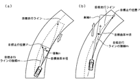
- FIG. 6 is a schematic diagram illustrating a setting operation of a forward gazing distance Ls according to the posture angle ⁇ of the first embodiment. It is a schematic diagram which shows the setting effect
- FIG. 6 is a schematic diagram illustrating a setting operation of a forward gazing distance Ls according to the posture angle ⁇ of the first embodiment. It is a schematic diagram which shows the setting effect
- FIG. 1 is a schematic diagram illustrating a vehicle steering system to which the vehicle travel support device of the first embodiment is applied.
- the vehicle steering system of the first embodiment includes left and right front wheels 1L and 1R, a steering gear 2, and a steering.
- the vehicle includes a wheel 3, a steering shaft 4, a steering actuator 5, a control unit 6, a wheel speed sensor 7, a camera 8, and a GPS receiver 9.
- the steering gear 2 converts the rotational motion input to the steering shaft 4 into a parallel motion in the vehicle width direction when the driver rotates the steering wheel 3, and steers the left and right front wheels 1L and 1R.
- the steering actuator 5 is, for example, an electric motor, and outputs torque to the steering shaft 4 to steer the left and right front wheels 1L and 1R.
- the wheel speed sensor 7 is provided in each wheel and detects the rotational speed of the wheel.
- the camera 8 images the front of the host vehicle.
- the GPS receiver 9 receives a signal from a GPS satellite and detects its own vehicle position with reference to a map database.
- the control unit 6 inputs information from the wheel speed sensor 7, the camera 8, and the GPS receiver 9, drives the steering actuator 5 based on a predetermined control logic, and performs driving support. As a driving support, the control unit 6 detects that the vehicle's travel line deviates from the target travel line so that the vehicle travels on the target travel line in the center of the lane width of the travel path.
- a steering control that drives the steering actuator 5 to steer the left and right front wheels 1L and 1R so that the target traveling position (front gazing point) separated by the front gazing distance is set to Execute.
- FIG. 2 is a control block diagram of the control unit 6 according to the first embodiment.
- the control unit 6 includes a target travel line recognition unit 10, an attitude angle / lateral displacement detection unit (lateral displacement detection means) 11, and a vehicle speed detection unit. 12, a target travel position setting unit 13, a forward gazing point distance setting unit (gaze point distance setting means) 14, and a steering control unit 15 are provided, and the following steering control is performed.
- the target travel line recognition unit 10 recognizes the target travel line based on the captured image obtained from the camera 8 and the own vehicle position information obtained from the GPS receiver 9.
- the posture angle / lateral displacement detection unit 11 is based on the captured image obtained from the camera 8 and the vehicle position information obtained from the GPS receiver 9, and the posture angle ⁇ with respect to the road and the vehicle from the target travel line.
- the lateral displacement y of the car is calculated.
- the posture angle ⁇ is a vehicle axis line (a vehicle passing through the left and right center position of the host vehicle) with respect to a straight line parallel to the tangent line of the target driving line (hereinafter referred to as the tangent line of the target driving line) passing through the center position of the host vehicle This is an angle formed by a straight line extending in the front-rear direction.
- the attitude angle ⁇ is a positive (+) sign when the vehicle axis is facing the left and right outside of the travel path with respect to the tangent to the target travel line, and the vehicle axis travels with respect to the tangent to the target travel line. When facing the center of the road, the sign is negative (-).
- the vehicle speed detector 12 detects the vehicle speed (vehicle speed) V of the host vehicle based on signals from the wheel speed sensors 7.
- the calculation method of the vehicle speed V is arbitrary. For example, the average value of the wheel speeds of the four wheels and the average value of the wheel speeds of the left and right rear wheels that are the driven wheels may be used as the vehicle speed V.
- the target travel position setting unit 13 calculates, as the target travel position P, a position on the target travel line that is separated from the host vehicle by the forward gazing distance Ls.
- the forward gazing distance setting unit 14 includes a posture determination unit (posture determination unit) 14a that determines the direction of the host vehicle with respect to the road from the posture angle ⁇ , and determines the direction of the host vehicle with respect to the road, the vehicle speed V, and the lateral displacement y. Based on this, the forward gaze distance Ls is set.
- the steering control unit 15 calculates a target curve connecting the vehicle position and the target travel position P, calculates the steering control amount of the left and right front wheels 1L, 1R based on the target curve, and based on the calculated steering control amount The steering actuator 5 is driven.
- FIG. 3 is a flowchart showing the flow of the steering control process executed by the control unit 6 of the first embodiment, and each step will be described below.
- the vehicle speed detection unit 12 reads the sensor signal from the wheel speed sensor 7, and the target travel line recognition unit 10 and the posture angle / lateral displacement detection unit 11 capture the captured image from the camera 8 and the GPS receiver 9. And the vehicle position information from.
- the target travel line recognition unit 10 recognizes the target travel line based on the captured image obtained from the camera 8 and the own vehicle position information obtained from the GPS receiver 9.
- step S3 in the attitude angle / lateral displacement detection unit 11, based on the captured image obtained from the camera 8 and the own vehicle position information obtained from the GPS receiver 9, the attitude angle ⁇ of the vehicle with respect to the traveling road, The vehicle's lateral displacement y from the target travel line is calculated.
- the posture determination unit 14a determines the direction of the host vehicle with respect to the travel path from the posture angle ⁇ . If the sign of the attitude angle ⁇ is positive (+), it is determined that the vehicle is facing the outside of the road, and if the sign of the attitude angle ⁇ is negative ( ⁇ ), the car is facing the center of the road. If the posture angle ⁇ is zero, it is determined that the direction of the host vehicle is parallel to the travel path.
- step S5 the forward gazing distance setting unit 14 sets the forward gazing distance Ls based on the vehicle speed V, the lateral displacement y, and the direction of the host vehicle with respect to the travel path. A method for setting the forward gazing point distance Ls will be described later.
- step S6 the target travel position setting unit 13 calculates the position on the target travel line that is away from the subject vehicle's forward gazing distance Ls as the target travel position P.
- step S7 the steering control unit 15 calculates a target curve that connects the vehicle position and the target travel position P with a constant curvature, and calculates the steering control amounts of the left and right front wheels 1L and 1R according to the target curve.
- the steering control amount that passes on the target curve may be calculated, but a torque sensor is provided on the steering shaft 4 to detect the driver's steering intervention, and the steering control amount is set to zero at the time of steering intervention.
- step S8 the steering control unit 15 drives the steering actuator 5 based on the steering control amount.
- FIG. 4 shows the own vehicle position, the target travel line, the lateral displacement y, the attitude angle ⁇ , the forward gaze distance Ls, the target travel position P, and the target curve in the steering control of the first embodiment.
- the forward gaze distance setting unit 14 calculates a base value Ls_base of the forward gaze distance based on the vehicle speed V.
- the base value Ls_base is obtained by multiplying the vehicle speed V by a predetermined own constant set in advance.
- the base value Ls_base of the forward gazing point distance is shortened or extended based on the posture angle ⁇ and the lateral displacement y.
- the base value Ls_base of the forward gazing distance is not changed, and when the lateral displacement y is greater than or equal to the lateral displacement threshold y_th, depending on the posture angle ⁇ Change the base value Ls_base of the forward gazing point distance.
- the base value Ls_base of the forward gazing distance is shortened by a preset ratio. 2.
- the base value Ls_base of the forward gazing distance is extended at a preset rate. 3.
- the front gazing point distance setting unit 14 shortens the front gazing point distance when the vehicle is facing the outside of the travel path, compared to when the vehicle is facing the direction along the travel path.
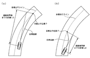
- the front gazing point distance setting unit 14 extends the front gazing point distance when the host vehicle is facing the center of the travel path as compared with the case where the host vehicle is facing the direction along the travel path. Further, the forward gazing distance setting unit 14 shortens the forward gazing distance when the host vehicle is facing the outside of the travel path, compared to when the host vehicle is facing the center of the travel path.
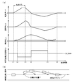
- FIG. 5 is a time chart showing the steering control action of the first embodiment when a driver's steering intervention is made on a straight road, and a schematic diagram showing a state of the vehicle.
- the turning angle ⁇ and lateral displacement y of the left and right front wheels 1L, 1R are positive (+) on the left side and negative ( ⁇ ) on the right side
- the attitude angle ⁇ is the vehicle axis relative to the tangent m of the target travel line.
- n is facing the left and right outer sides of the travel path is positive (+)
- the case where the vehicle axis is facing the center of the travel path is negative ( ⁇ ).
- the vehicle is traveling on the target travel line.
- the turning angle ⁇ starts to increase due to the driver's steering intervention, and the posture angle ⁇ and the lateral displacement y increase accordingly, but the lateral displacement y is less than the lateral displacement threshold y_th, so the forward gaze distance Ls remains the base value Ls_base of the forward gaze distance.
- the forward gazing distance Ls is shortened from the base value Ls_base.
- the steering angle of the driver ends and the turning angle ⁇ starts to decrease, so that the posture angle ⁇ starts to decrease.
- the posture angle ⁇ changes from positive to negative, so the forward gazing distance Ls is extended beyond the base value Ls_base.
- the front gazing point distance Ls returns to the base value Ls_base of the front gazing point distance.
- the vehicle returns to the target travel line.
- the fact that the vehicle is facing the outside of the road means that the vehicle is moving in a direction deviating from the target travel line, and there is a high possibility of lane departure.
- the tendency of the vehicle to deviate can be eliminated at an early stage, and lane departure can be suppressed. Therefore, even when the vehicle posture deviates from the target travel line due to a driver's steering intervention or the like on a curve with a small radius of curvature, the posture can be quickly returned, and lane departure can be suppressed.
- the smaller the radius of curvature of the traveling path the shorter the forward gazing distance, but even when the possibility of lane departure is low, the forward gazing point is uniformly uniform. If the distance is shortened, the control gain of the steering control becomes too strong and the vehicle behavior changes greatly, so that the driver feels uncomfortable.
- the front gaze distance Ls is set by extending the base value Ls_base of the front gaze distance. To do.
- the target travel position P becomes a position farther from the host vehicle.
- the larger the radius of curvature of the target curve the smaller the steering control amount of the left and right front wheels 1L, 1R required to pass on the target curve. That is, the control gain of the steering control is weakened.
- the fact that the vehicle is facing the center of the travel path means that the vehicle is moving in the direction of returning to the target travel line, and the possibility of lane departure is low.
- the movement toward the target travel line is suppressed while the movement returning to the target travel line is slow.
- the movement will match the driving sensation of the driver. For this reason, it is possible to suppress a sudden change in vehicle behavior when returning to the target travel line after the driver's steering intervention or starting steering control from a position deviating from the target travel line, and to reduce the uncomfortable feeling given to the driver.
- the steering reaction force increases when deviating from the target travel line, and the steering reaction force decreases when returning to the target travel line, so that the driver feels uncomfortable.
- the lateral displacement y when the lateral displacement y is large, the lane departure can be more reliably suppressed by shortening the front gazing point distance Ls. Further, when the lateral displacement y is small, the forward gazing distance Ls is not shortened, so that the control gain when the possibility of lane departure is low can be suppressed, and the uncomfortable feeling given to the driver can be reduced.
- the forward gaze distance Ls when the host vehicle is directed toward the center of the road, when the lateral displacement y is greater than or equal to the lateral displacement threshold y_th, the forward gaze distance Ls is extended beyond the base value Ls_base, and the lateral displacement y Is less than the lateral displacement threshold y_th, the forward gazing point distance Ls remains as the base value Ls_base.
- the control gain of the steering control for returning the vehicle to the target travel line is small regardless of the forward gazing distance Ls.In this case, the forward gazing distance Ls should not be increased. The vehicle can be returned to the target travel line at an early stage.
- the control gain since the control gain is large when the lateral displacement y is large, in this case, by increasing the forward gazing distance Ls, the control gain can be made as small as possible to reduce the uncomfortable feeling given to the driver.
- the vehicle travel support apparatus has the following effects. (1) For vehicles that support the traveling of the vehicle so that the vehicle travels the target traveling position P set by the vehicle by setting a target traveling position P that is separated by a forward gazing distance Ls in front of the vehicle on the traveling path.
- the posture determination unit 14a that determines the direction of the own vehicle with respect to the traveling road, and when the own vehicle faces the outer side of the traveling road, the front gazing point is more than when the own vehicle is parallel to the traveling road.
- a forward gazing point distance setting unit 14 that sets a forward gazing point distance Ls obtained by shortening the distance base value Ls_base.
- the posture determination unit 14a that determines the direction of the vehicle with respect to the traveling road, and when the own vehicle is facing the center of the traveling road, the front note is more than the case where the direction of the own vehicle is parallel to the traveling road.
- a posture angle / lateral displacement detector 11 that detects the lateral displacement y of the host vehicle from the target travel line is provided, and the forward gaze distance setting unit 14 is used when the host vehicle is facing the outside of the road.
- the detected lateral displacement y is greater than or equal to the lateral displacement threshold y_th
- a shorter forward gazing distance Ls is set than when the lateral displacement y is less than the lateral displacement threshold y_th.
- a posture angle / lateral displacement detection unit 11 that detects the lateral displacement y of the vehicle from the target travel line is provided, and the forward gaze distance setting unit 14 is used when the vehicle is facing the center of the travel path. If the detected lateral displacement y is greater than or equal to the lateral displacement threshold y_th, a longer forward gazing distance Ls is set than when the lateral displacement y is less than the lateral displacement threshold y_th. Thereby, it is possible to achieve both the early return to the target travel line and the reduction of the uncomfortable feeling given to the driver.
- the second embodiment is an example in which the forward gazing point distance Ls is set based on the distance to the road boundary line ahead of the vehicle, and different parts from the first embodiment will be described.
- the attitude angle / lateral displacement detection unit (boundary distance detection means) 11 is based on the captured image obtained from the camera 8 and the own vehicle position information obtained from the GPS receiver 9, and the attitude angle of the vehicle with respect to the traveling road
- a distance Ld to the road boundary line ahead of the vehicle is calculated.
- the forward gazing point distance setting unit 14 sets the forward gazing point distance Ls based on the vehicle speed V, the lateral displacement y, the posture angle ⁇ , and the distance Ld to the road boundary line ahead of the vehicle.
- the steering control process of the second embodiment is substantially the same as the steering control process of the first embodiment shown in FIG. 3 except that the distance Ld to the road boundary line ahead of the vehicle is calculated in step S3, and in step S4.
- the difference is that the forward gaze point distance Ls is set based on the vehicle speed V, the lateral displacement y, the posture angle ⁇ , and the distance Ld to the road boundary line ahead of the vehicle.
- the base value Ls_base of the forward gazing distance according to the vehicle speed V is calculated, and the base value Ls_base is changed according to the orientation of the posture angle ⁇ and the lateral displacement y, as in the first embodiment.
- the second embodiment when the distance Ld to the road boundary line ahead of the vehicle is equal to or smaller than the boundary distance threshold Ld_th with respect to the forward gazing distance Ls set according to the direction of the posture angle ⁇ and the lateral displacement y. Sets the forward gazing point distance Ls to the distance Ld.
- the forward gazing distance Ls uses the base value Ls_base as the own vehicle with respect to the traveling road. The value is changed according to the direction and the lateral displacement y.
- the forward gazing distance Ls is set to the distance Ld as shown in FIG.
- the lane departure can be more reliably suppressed by reducing the forward gazing distance Ls.
- the forward gaze distance Ls is limited to the distance Ld to the road boundary line, so that it can sufficiently cope with a curve with a small curvature radius. Since the base value Ls_base of the viewpoint distance can be made longer than in the case of the first embodiment, an effect that the uncomfortable feeling given to the driver can be further reduced can be obtained.
- the vehicle travel support apparatus of the second embodiment has the effects listed below.
- a posture angle / lateral displacement detector (boundary distance detector) 11 for detecting the distance Ld to the road boundary in front of the vehicle is provided, and the forward gaze distance setting unit 14 is connected to the detected road boundary.
- the forward gazing distance Ls is shortened compared to the case where the distance Ld to the road boundary exceeds the boundary distance threshold Ld_th.
- the base value Ls_base of the forward gazing point distance can be set longer, the uncomfortable feeling given to the driver can be further reduced.
- the forward gazing point distance setting unit 14 sets the forward gazing point distance Ls equal to the distance Ld to the road boundary when the distance Ld to the detected road boundary is equal to or less than the boundary distance threshold Ld_th. Therefore, an appropriate target travel position P that does not deviate from the travel path can be set.
- the base value Ls_base of the forward gazing point distance may be shortened or extended based only on the direction of the host vehicle with respect to the travel path.
- the shortening rate or the extending rate may be variable according to the posture angle ⁇ , the lateral displacement y, or the distance Ld to the road boundary line ahead of the vehicle. For example, in the case of the posture angle ⁇ , the shortening rate or the extension rate is increased as the absolute value
Landscapes
- Engineering & Computer Science (AREA)
- Transportation (AREA)
- Mechanical Engineering (AREA)
- Chemical & Material Sciences (AREA)
- Combustion & Propulsion (AREA)
- Steering Control In Accordance With Driving Conditions (AREA)
- Automation & Control Theory (AREA)
- Traffic Control Systems (AREA)
Abstract
Priority Applications (5)
| Application Number | Priority Date | Filing Date | Title |
|---|---|---|---|
| US14/435,201 US20150266508A1 (en) | 2012-10-25 | 2012-10-25 | Vehicle travel assistance device |
| PCT/JP2012/077622 WO2014064805A1 (fr) | 2012-10-25 | 2012-10-25 | Dispositif d'aide au déplacement d'un véhicule |
| EP12887153.0A EP2913249A4 (fr) | 2012-10-25 | 2012-10-25 | Dispositif d'aide au déplacement d'un véhicule |
| JP2014543080A JPWO2014064805A1 (ja) | 2012-10-25 | 2012-10-25 | 車両用走行支援装置 |
| CN201280076304.5A CN104703861A (zh) | 2012-10-25 | 2012-10-25 | 车辆用行驶辅助装置 |
Applications Claiming Priority (1)
| Application Number | Priority Date | Filing Date | Title |
|---|---|---|---|
| PCT/JP2012/077622 WO2014064805A1 (fr) | 2012-10-25 | 2012-10-25 | Dispositif d'aide au déplacement d'un véhicule |
Publications (1)
| Publication Number | Publication Date |
|---|---|
| WO2014064805A1 true WO2014064805A1 (fr) | 2014-05-01 |
Family
ID=50544203
Family Applications (1)
| Application Number | Title | Priority Date | Filing Date |
|---|---|---|---|
| PCT/JP2012/077622 WO2014064805A1 (fr) | 2012-10-25 | 2012-10-25 | Dispositif d'aide au déplacement d'un véhicule |
Country Status (5)
| Country | Link |
|---|---|
| US (1) | US20150266508A1 (fr) |
| EP (1) | EP2913249A4 (fr) |
| JP (1) | JPWO2014064805A1 (fr) |
| CN (1) | CN104703861A (fr) |
| WO (1) | WO2014064805A1 (fr) |
Cited By (2)
| Publication number | Priority date | Publication date | Assignee | Title |
|---|---|---|---|---|
| JP2016107658A (ja) * | 2014-12-02 | 2016-06-20 | 日産自動車株式会社 | 車両の操舵制御装置及び車両の操舵制御方法 |
| JP6192782B1 (ja) * | 2016-08-04 | 2017-09-06 | 三菱電機株式会社 | 自動操舵制御装置および自動操舵制御方法 |
Families Citing this family (14)
| Publication number | Priority date | Publication date | Assignee | Title |
|---|---|---|---|---|
| US20150316386A1 (en) * | 2014-04-30 | 2015-11-05 | Toyota Motor Engineering & Manufacturing North America, Inc. | Detailed map format for autonomous driving |
| US20150316387A1 (en) | 2014-04-30 | 2015-11-05 | Toyota Motor Engineering & Manufacturing North America, Inc. | Detailed map format for autonomous driving |
| US9644972B2 (en) * | 2015-03-06 | 2017-05-09 | Tallysman Wireless Inc. | Method for tracking a path taken by a vehicle |
| CN109415060B (zh) * | 2016-07-05 | 2022-03-01 | 日产自动车株式会社 | 行驶控制方法及行驶控制装置 |
| JP6589760B2 (ja) * | 2016-07-07 | 2019-10-16 | 株式会社デンソー | 車両制御装置 |
| JP6809020B2 (ja) * | 2016-07-27 | 2021-01-06 | いすゞ自動車株式会社 | 操舵補助装置及び操舵補助方法 |
| JP6747182B2 (ja) * | 2016-08-30 | 2020-08-26 | 愛知製鋼株式会社 | 車両用の姿勢検出システム |
| CA3036337A1 (fr) * | 2016-09-09 | 2018-03-15 | Nissan Motor Co., Ltd. | Procede de controle de trajet de vehicule et dispositif de controle de trajet de vehicule |
| JP7003630B2 (ja) | 2017-12-20 | 2022-01-20 | いすゞ自動車株式会社 | 操舵制御装置及び操舵制御方法 |
| US20210078573A1 (en) * | 2018-01-19 | 2021-03-18 | Hitachi Automotive Systems, Ltd. | Driver Assistance Device, Driver Assistance Method, and Driver Assistance System |
| CN108454619B (zh) * | 2018-03-30 | 2020-06-02 | 吉利汽车研究院(宁波)有限公司 | 一种驾驶辅助方法及系统 |
| JP7229710B2 (ja) * | 2018-09-26 | 2023-02-28 | 本田技研工業株式会社 | 車両制御装置、車両制御方法、およびプログラム |
| CN111857469B (zh) * | 2020-07-09 | 2021-10-15 | 中国第一汽车股份有限公司 | 一种道路环境信息的重构方法、装置及设备 |
| KR20230055722A (ko) * | 2021-10-19 | 2023-04-26 | 현대모비스 주식회사 | 차량의 타겟 감지 시스템 및 방법 |
Citations (4)
| Publication number | Priority date | Publication date | Assignee | Title |
|---|---|---|---|---|
| JPH10167100A (ja) | 1996-12-09 | 1998-06-23 | Toyota Motor Corp | 車両の操舵制御装置 |
| JP2001048035A (ja) * | 1999-08-10 | 2001-02-20 | Nissan Motor Co Ltd | 車線追従装置 |
| JP2008059366A (ja) * | 2006-08-31 | 2008-03-13 | Nissan Motor Co Ltd | 操舵角決定装置、自動車及び操舵角決定方法 |
| JP2010076573A (ja) | 2008-09-25 | 2010-04-08 | Toyota Motor Corp | 操舵制御装置 |
Family Cites Families (3)
| Publication number | Priority date | Publication date | Assignee | Title |
|---|---|---|---|---|
| JP4108706B2 (ja) * | 2005-10-31 | 2008-06-25 | 三菱電機株式会社 | 車線逸脱防止装置 |
| JP4638370B2 (ja) * | 2006-03-29 | 2011-02-23 | 富士重工業株式会社 | 車線逸脱防止装置 |
| JP4735676B2 (ja) * | 2008-08-06 | 2011-07-27 | 株式会社デンソー | 走行支援装置 |
-
2012
- 2012-10-25 US US14/435,201 patent/US20150266508A1/en not_active Abandoned
- 2012-10-25 WO PCT/JP2012/077622 patent/WO2014064805A1/fr active Application Filing
- 2012-10-25 CN CN201280076304.5A patent/CN104703861A/zh active Pending
- 2012-10-25 EP EP12887153.0A patent/EP2913249A4/fr not_active Withdrawn
- 2012-10-25 JP JP2014543080A patent/JPWO2014064805A1/ja active Pending
Patent Citations (4)
| Publication number | Priority date | Publication date | Assignee | Title |
|---|---|---|---|---|
| JPH10167100A (ja) | 1996-12-09 | 1998-06-23 | Toyota Motor Corp | 車両の操舵制御装置 |
| JP2001048035A (ja) * | 1999-08-10 | 2001-02-20 | Nissan Motor Co Ltd | 車線追従装置 |
| JP2008059366A (ja) * | 2006-08-31 | 2008-03-13 | Nissan Motor Co Ltd | 操舵角決定装置、自動車及び操舵角決定方法 |
| JP2010076573A (ja) | 2008-09-25 | 2010-04-08 | Toyota Motor Corp | 操舵制御装置 |
Non-Patent Citations (1)
| Title |
|---|
| See also references of EP2913249A4 |
Cited By (3)
| Publication number | Priority date | Publication date | Assignee | Title |
|---|---|---|---|---|
| JP2016107658A (ja) * | 2014-12-02 | 2016-06-20 | 日産自動車株式会社 | 車両の操舵制御装置及び車両の操舵制御方法 |
| JP6192782B1 (ja) * | 2016-08-04 | 2017-09-06 | 三菱電機株式会社 | 自動操舵制御装置および自動操舵制御方法 |
| JP2018020676A (ja) * | 2016-08-04 | 2018-02-08 | 三菱電機株式会社 | 自動操舵制御装置および自動操舵制御方法 |
Also Published As
| Publication number | Publication date |
|---|---|
| JPWO2014064805A1 (ja) | 2016-09-05 |
| EP2913249A1 (fr) | 2015-09-02 |
| CN104703861A (zh) | 2015-06-10 |
| US20150266508A1 (en) | 2015-09-24 |
| EP2913249A4 (fr) | 2015-12-23 |
Similar Documents
| Publication | Publication Date | Title |
|---|---|---|
| WO2014064805A1 (fr) | Dispositif d'aide au déplacement d'un véhicule | |
| US8457868B2 (en) | Lane keeping assist device and lane keeping assist method | |
| JP6076394B2 (ja) | 車両用操舵装置および車両操舵制御方法 | |
| US9302704B2 (en) | Power steering controller for vehicle | |
| US10336366B2 (en) | Driving support apparatus for vehicle | |
| JP5790401B2 (ja) | 車両用走行支援装置 | |
| JP5255988B2 (ja) | 操舵支援装置 | |
| US8544592B2 (en) | Steering apparatus for vehicle | |
| JP4684698B2 (ja) | 車両の操舵制御装置 | |
| CN107914767B (zh) | 转向操纵辅助装置 | |
| JP5808977B2 (ja) | 車両のヨーモーメント発生旋回効率化装置 | |
| JP5813196B1 (ja) | 電動パワーステアリング装置 | |
| JP7216589B2 (ja) | 自動操舵制御装置 | |
| US9308938B2 (en) | Vehicle power steering control apparatus | |
| JP5853552B2 (ja) | 車両用走行制御装置 | |
| JP5532684B2 (ja) | 車両の走行制御装置および車両の走行制御方法 | |
| JP6663767B2 (ja) | 車両の操舵支援装置 | |
| KR101997429B1 (ko) | 차량의 차선 유지 제어 방법 및 이를 구현하는 차선 유지 제어 장치 | |
| CN109562783B (zh) | 转向辅助装置及转向辅助方法 | |
| WO2018189912A1 (fr) | Procédé et dispositif de commande de véhicule | |
| JP2020015444A (ja) | 車両制御装置 | |
| JP2007168641A (ja) | 可変舵角操舵装置及びその方法、並びにその可変舵角操舵装置を搭載した自動車 | |
| JP2008013118A (ja) | 車両用操舵装置、自動車、車両操舵方法及び操舵中立点設定方法 | |
| JP4770859B2 (ja) | 車両逸脱防止装置 | |
| JP6623082B2 (ja) | 車両制御装置 |
Legal Events
| Date | Code | Title | Description |
|---|---|---|---|
| 121 | Ep: the epo has been informed by wipo that ep was designated in this application |
Ref document number: 12887153 Country of ref document: EP Kind code of ref document: A1 |
|
| ENP | Entry into the national phase |
Ref document number: 2014543080 Country of ref document: JP Kind code of ref document: A |
|
| WWE | Wipo information: entry into national phase |
Ref document number: 14435201 Country of ref document: US |
|
| REEP | Request for entry into the european phase |
Ref document number: 2012887153 Country of ref document: EP |
|
| WWE | Wipo information: entry into national phase |
Ref document number: 2012887153 Country of ref document: EP |
|
| NENP | Non-entry into the national phase |
Ref country code: DE |