WO2014050868A1 - クラッチ - Google Patents
クラッチ Download PDFInfo
- Publication number
- WO2014050868A1 WO2014050868A1 PCT/JP2013/075873 JP2013075873W WO2014050868A1 WO 2014050868 A1 WO2014050868 A1 WO 2014050868A1 JP 2013075873 W JP2013075873 W JP 2013075873W WO 2014050868 A1 WO2014050868 A1 WO 2014050868A1
- Authority
- WO
- WIPO (PCT)
- Prior art keywords
- rotating body
- driven
- clutch
- pin
- slide piece
- Prior art date
- Legal status (The legal status is an assumption and is not a legal conclusion. Google has not performed a legal analysis and makes no representation as to the accuracy of the status listed.)
- Ceased
Links
Images



Classifications
-
- F—MECHANICAL ENGINEERING; LIGHTING; HEATING; WEAPONS; BLASTING
- F16—ENGINEERING ELEMENTS AND UNITS; GENERAL MEASURES FOR PRODUCING AND MAINTAINING EFFECTIVE FUNCTIONING OF MACHINES OR INSTALLATIONS; THERMAL INSULATION IN GENERAL
- F16D—COUPLINGS FOR TRANSMITTING ROTATION; CLUTCHES; BRAKES
- F16D23/00—Details of mechanically-actuated clutches not specific for one distinct type
- F16D23/12—Mechanical clutch-actuating mechanisms arranged outside the clutch as such
-
- F—MECHANICAL ENGINEERING; LIGHTING; HEATING; WEAPONS; BLASTING
- F16—ENGINEERING ELEMENTS AND UNITS; GENERAL MEASURES FOR PRODUCING AND MAINTAINING EFFECTIVE FUNCTIONING OF MACHINES OR INSTALLATIONS; THERMAL INSULATION IN GENERAL
- F16D—COUPLINGS FOR TRANSMITTING ROTATION; CLUTCHES; BRAKES
- F16D41/00—Freewheels or freewheel clutches
- F16D41/06—Freewheels or freewheel clutches with intermediate wedging coupling members between an inner and an outer surface
- F16D41/08—Freewheels or freewheel clutches with intermediate wedging coupling members between an inner and an outer surface with provision for altering the freewheeling action
- F16D41/086—Freewheels or freewheel clutches with intermediate wedging coupling members between an inner and an outer surface with provision for altering the freewheeling action the intermediate members being of circular cross-section and wedging by rolling
- F16D41/088—Freewheels or freewheel clutches with intermediate wedging coupling members between an inner and an outer surface with provision for altering the freewheeling action the intermediate members being of circular cross-section and wedging by rolling the intermediate members being of only one size and wedging by a movement not having an axial component, between inner and outer races, one of which is cylindrical
-
- F—MECHANICAL ENGINEERING; LIGHTING; HEATING; WEAPONS; BLASTING
- F16—ENGINEERING ELEMENTS AND UNITS; GENERAL MEASURES FOR PRODUCING AND MAINTAINING EFFECTIVE FUNCTIONING OF MACHINES OR INSTALLATIONS; THERMAL INSULATION IN GENERAL
- F16D—COUPLINGS FOR TRANSMITTING ROTATION; CLUTCHES; BRAKES
- F16D15/00—Clutches with wedging balls or rollers or with other wedgeable separate clutching members
-
- F—MECHANICAL ENGINEERING; LIGHTING; HEATING; WEAPONS; BLASTING
- F16—ENGINEERING ELEMENTS AND UNITS; GENERAL MEASURES FOR PRODUCING AND MAINTAINING EFFECTIVE FUNCTIONING OF MACHINES OR INSTALLATIONS; THERMAL INSULATION IN GENERAL
- F16D—COUPLINGS FOR TRANSMITTING ROTATION; CLUTCHES; BRAKES
- F16D27/00—Magnetically- or electrically- actuated clutches; Control or electric circuits therefor
- F16D27/10—Magnetically- or electrically- actuated clutches; Control or electric circuits therefor with an electromagnet not rotating with a clutching member, i.e. without collecting rings
- F16D27/108—Magnetically- or electrically- actuated clutches; Control or electric circuits therefor with an electromagnet not rotating with a clutching member, i.e. without collecting rings with axially movable clutching members
-
- F—MECHANICAL ENGINEERING; LIGHTING; HEATING; WEAPONS; BLASTING
- F16—ENGINEERING ELEMENTS AND UNITS; GENERAL MEASURES FOR PRODUCING AND MAINTAINING EFFECTIVE FUNCTIONING OF MACHINES OR INSTALLATIONS; THERMAL INSULATION IN GENERAL
- F16D—COUPLINGS FOR TRANSMITTING ROTATION; CLUTCHES; BRAKES
- F16D13/00—Friction clutches
- F16D13/76—Friction clutches specially adapted to incorporate with other transmission parts, i.e. at least one of the clutch parts also having another function, e.g. being the disc of a pulley
-
- F—MECHANICAL ENGINEERING; LIGHTING; HEATING; WEAPONS; BLASTING
- F16—ENGINEERING ELEMENTS AND UNITS; GENERAL MEASURES FOR PRODUCING AND MAINTAINING EFFECTIVE FUNCTIONING OF MACHINES OR INSTALLATIONS; THERMAL INSULATION IN GENERAL
- F16D—COUPLINGS FOR TRANSMITTING ROTATION; CLUTCHES; BRAKES
- F16D23/00—Details of mechanically-actuated clutches not specific for one distinct type
- F16D23/12—Mechanical clutch-actuating mechanisms arranged outside the clutch as such
- F16D2023/123—Clutch actuation by cams, ramps or ball-screw mechanisms
Definitions
- the technology of the present disclosure relates to a clutch that switches a power transmission state between a driving side rotating body and a driven side rotating body by connecting or releasing the connection.
- Patent Document 1 proposes to provide a clutch between the crankshaft and the auxiliary machine for the purpose of reducing the friction of the internal combustion engine.
- the clutch described in Patent Document 1 includes a drive-side rotator that is connected to a crankshaft and rotates, and a driven-side rotator that is connected to an auxiliary machine and can rotate relative to the drive-side member.
- the clutch is maintained in the connected state by pressing these rotating bodies by the magnetic force of the magnet. Further, energization control is performed on the coil provided in the clutch to generate a magnetic field that cancels the magnetic force, thereby releasing the clutch.
- An object of the present disclosure is to provide a clutch capable of switching a power transmission state while suppressing an increase in size even when a torque to be transmitted is large.
- a clutch for solving the above-described problems is provided between a driving side rotating body, a first position connected to the driving side rotating body, and a second position where the connection of the driving side rotating body is released.
- a driven-side rotating body movable along the axial direction of the driving-side rotating body; a biasing member that biases the driven-side rotating body from the second position toward the first position; and the driven A spiral groove provided in the side rotating body and extending in the biasing direction of the biasing member, and a pin insertable into the spiral groove.
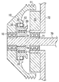
- Sectional drawing of the clutch which concerns on one Embodiment.
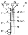
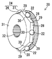
- the perspective view of the slide piece of FIG. FIG. 4 is a cross-sectional perspective view of a groove in the slide piece of FIG. 3.
- (A) is a figure when a clutch is in a connection state
- (b) is a figure when a clutch is in a connection release state.
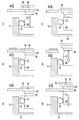
- (A), (b) is sectional drawing of the solenoid of FIG. (A)-(f) is a figure which shows operation
- This embodiment shows a clutch that is applied to a vehicle, more specifically, a clutch that is provided between a crankshaft of an engine and a compressor of an air conditioner and switches a power transmission state between the two.
- the clutch includes a pulley 10 and a slide piece 20.
- the pulley 10 corresponds to a driving side rotating body
- the slide piece 20 corresponds to a driven side rotating body.
- the pulley 10 is formed in a substantially truncated cone shape whose outer diameter increases toward the base end (right side in FIG. 1). A plurality of grooves 11 around which the belt is wound are provided on the outer peripheral surface of the base end portion of the pulley 10. The belt is also wound around the crankshaft, and the crankshaft and the pulley 10 rotate in synchronization with the belt. On the inner peripheral surface of the pulley 10, a protruding portion 12 that protrudes from the inner peripheral surface and extends in the axial direction is formed. The protrusion 12 is formed in an annular shape centering on the axis of the pulley 10. The pulley 10 is supported by a compressor shaft 70 of a compressor so as to be relatively rotatable through a bearing 13 provided at a tip portion (left side in FIG. 1).
- the compressor shaft 70 is supported by the engine body 72 by a bearing 71 so as to be relatively rotatable. When the compressor shaft 70 rotates, the compressor enters a driving state and compresses the refrigerant.
- An annular plate 73 is fixed to the surface of the engine body 72 that faces the pulley 10.
- a straight spline 74 is formed on the outer peripheral surface of the portion located between the bearings 13 and 71.
- the slide piece 20 is fitted to the straight spline 74. Therefore, the slide piece 20 rotates integrally with the compressor shaft 70 and is movable in the axial direction with respect to the compressor shaft 70.
- the slide piece 20 is urged toward the pulley 10 (left side in FIG. 1) by a coiled spring 21 disposed between the slide piece 20 and the engine body 72.
- the spring 21 corresponds to an urging member.
- a plurality of balls 22 are arranged on the outer peripheral surface of the slide piece 20.
- the diameter Db of the ball 22 is substantially the same as the distance from the outer peripheral surface of the slide piece 20 to the protruding portion 12 of the pulley 10. Therefore, the ball 22 contacts the outer peripheral surface of the slide piece 20 and the inner peripheral surface of the protruding portion 12.
- a holder 23 that restricts the movement of the ball 22 is fixed to the outer peripheral surface of the slide piece 20.
- the axes of the pulley 10, the compressor shaft 70, and the slide piece 20 coincide with each other, and hereinafter, the extending direction of the axis is referred to as an axial direction.
- the slide piece 20 includes a holding portion 24 that holds the ball 22 on its outer peripheral surface, and a groove portion 25 that is provided closer to the engine body 72 (right side in FIG. 2) than the holding portion 24. And.
- the holding portion 24 includes a cylindrical portion 26 having a substantially circular cross-sectional shape, and a hexagonal column portion 27 having a regular hexagonal cross-sectional shape.
- the hexagonal column portion 27 includes six side portions 28 and corner portions 29, respectively.
- Have The diameter of the circle passing through the midpoint part 30 of the side part 28 is the same as the outer diameter of the end face 31 of the cylindrical part 26.
- the diameter of the circle passing through the corner portion 29 is larger than the outer diameter of the end surface 31 of the cylindrical portion 26. Therefore, the cross section of the cylindrical portion 26 gradually changes from a circular shape to a hexagonal shape toward the hexagonal column portion 27.
- a hole 32 that extends in the axial direction and fits with the straight spline 74 of the compressor shaft 70 is formed in the central portion of the holding portion 24.
- the groove 25 has a spiral groove 33 and an annular groove 34.
- the spiral groove 33 extends so as to turn 540 ° clockwise around the axis of the slide piece 20 with the position located at the top in these drawings as the starting point 35 (0 °).
- the diameter is reduced as the distance from the circumferential direction increases. That is, the standing surface, that is, the side surface (or side wall) 36 facing the hexagonal column portion 27 of the holding portion 24 in the spiral groove 33 is closer to the pulley 10 at a location away from the starting portion 35 in the circumferential direction.
- an inner diameter edge of the first circumferential side surface 361 and an outer diameter edge of the second circumferential side surface 362 are connected by the circumferential surface 37. Therefore, the spiral groove 33 is formed in a stepped cross section as shown in FIG.
- the direction in which the spiral groove 33 converges toward the axis of the slide piece 20 is the direction in which the spiral groove 33 extends. That is, the direction toward the pulley 10 in the axial direction, in other words, the direction in which the slide piece 20 is urged by the spring 21 is the direction in which the spiral groove 33 extends.
- annular groove 34 extending in the circumferential direction of the axis of the slide piece 20 is formed over the entire circumference of the slide piece 20 on the front side (left side in FIG. 2) of the spiral groove 33 in the biasing direction of the spring 21. ing.
- the annular groove 34 is formed continuously from the spiral groove 33 with the end point portion 38 at a position turned 540 ° from the start point portion 35 of the spiral groove 33 as the start point portion 40.
- the annular groove 34 is provided such that the position of the standing surface, that is, the side surface (or side wall) 39 in the axial direction is substantially constant.
- the radial length of the side surface 39 gradually decreases as it is distant from the starting point portion 40 in the circumferential direction. Therefore, when the circular groove 34 makes one round (540 ° to 900 °), it returns to the end point portion 38 of the spiral groove 33.
- the retainer 23 has a cylindrical shape, and has a substantially hexagonal inner hole 41 having the same shape as the cross section of the hexagonal column 27 of the retainer 24.
- the holder 23 is fixed to the hexagonal column portion 27 of the slide piece 20 by inserting the holding portion 24 of the slide piece 20 into the inner hole 41. Therefore, the cage 23 rotates integrally with the slide piece 20.
- a holding hole 42 centering on the midpoint portion 30 is formed in a portion corresponding to each midpoint portion 30 of the holding portion 24.
- the holding hole 42 is formed in a shape having a shorter length in the circumferential direction toward the cylindrical portion 26 of the holding portion 24.
- the ball 22 By disposing the ball 22 in the holding hole 42, the ball is held at a predetermined position on the outer peripheral surface of the slide piece 20.
- the ball 22 is allowed to move to the outer peripheral surface of the cylindrical portion 26 and the outer peripheral surface of the hexagonal column portion 27, and when positioned on the outer peripheral surface of the hexagonal column portion 27, the ball 22 moves in the circumferential direction within a predetermined range. Movement is also permitted.
- FIG. 6A shows a state in which the ball 22 is positioned on the outer periphery of the hexagonal column portion 27 in the holding portion 24 of the slide piece 20.
- the pulley 10 and the slide piece 20 are coupled, that is, the clutch is coupled, and the rotational power of the pulley 10 is transmitted to the slide piece 20.
- the compressor shaft 70 rotates and the compressor is in a driving state.
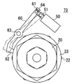
- a solenoid 50 and a pin 60 connected to the solenoid 50 are disposed on the outer peripheral side of the slide piece 20.
- the pin 60 has a long hole 61 at one end, and an insertion portion 62 that can be inserted into the groove 25 of the slide piece 20 at the other end.
- the plate 73 has a shaft portion 63 that supports the pin 60 so as to be rotatable and immovable in the axial direction of the pulley 10 between one end portion and the other end portion of the pin 60.
- the illustration of the solenoid 50 and the pin 60 is omitted.
- the movable iron core 51 of the solenoid 50 is connected to the long hole 61 of the pin 60 through a connecting member 64. Then, as shown by a solid line in FIG. 7, when the movable iron core 51 protrudes from the solenoid 50, the pin 60 rotates around the shaft portion 63 and the insertion portion 62 is inserted into the groove portion 25. On the other hand, as shown by a two-dot chain line in FIG. 7, when the movable iron core 51 is drawn into the solenoid 50, the pin 60 rotates about the shaft portion 63 and the insertion portion 62 is drawn out from the groove portion 25.
- the solenoid 50 includes a movable iron core 51 and a yoke 52 that holds the movable iron core 51, and a coil 53 disposed in the yoke 52 and a receiving portion (fixed).
- Iron core) 58 and magnet 54 are provided.
- a hole 55 is formed at the tip of the movable iron core 51.
- the connecting member 64 attached to the hole 55 is inserted into the long hole 61 of the pin 60 (see FIG. 7).
- a ring member 56 is attached to the outer periphery of the movable iron core 51, and a spring 57 is disposed between the ring member 56 and the yoke 52. The spring 57 exerts a biasing force in the direction in which the movable iron core 51 protrudes from the yoke 52 (right direction in the drawing).
- the movable iron core 51 is moved to selectively switch between the insertion state in which the pin 60 is inserted into the spiral groove 33 and the extraction state in which the pin 60 is pulled out. be able to. Moreover, when the coil 53 is not energized, the pin 60 can be maintained in the state after switching.
- FIG. 9A shows a state in which the slide piece 20 is biased by the biasing force of the spring 21 and is closest to the pulley 10 in the axial direction.
- the ball 22 is positioned on the outer periphery of the hexagonal column portion 27 of the slide piece 20.
- the pulley 10 rotates in this state, the ball 22 is non-rotatably fitted between the protruding portion 12 of the pulley 10 and the slide piece 20 to connect the pulley 10 and the slide piece 20 so that power can be transmitted. Therefore, the clutch is in a connected state, the slide piece 20 and the compressor shaft 70 rotate integrally with the pulley 10, and the compressor is driven. Note that the position of the slide piece 20 when the clutch is in the engaged state in this way corresponds to the first position.
- the ball 22 provided on the outer periphery of the slide piece 20 moves from a position on the outer peripheral surface of the hexagonal column portion 27 to a position on the outer peripheral surface of the cylindrical portion 26 as the slide piece 20 moves in the axial direction. And move.
- the slide piece 20 may still maintain the rotation state due to its inertia.
- the rotational force of the slide piece 20 is not converted into an axial force. Therefore, the movement of the slide piece 20 in the axial direction after the connection between the slide piece 20 and the pulley 10 is released is restricted.
- the pin 60 in order to release the clutch, the pin 60 is inserted into the spiral groove 33 of the slide piece 20 in a rotating state. Then, a part of the rotational force of the slide piece 20 is converted into an axial force, and the slide piece 20 is moved to the second position. Therefore, the force necessary to release the clutch can be obtained from the rotational force of the slide piece 20, and even if the torque to be transmitted is large, the power transmission state is suppressed while suppressing the enlargement of the clutch. Can be switched.
- the spiral groove 33 is formed in a step shape in a sectional view along the axial direction. Therefore, the length in the axial direction of the portion where the spiral groove 33 is formed can be shortened, and the enlargement of the clutch can be more suitably suppressed.
- the pin 60 is in sliding contact with the annular groove 34 to restrict the movement of the slide piece 20 in the axial direction after the connection between the pulley 10 and the slide piece 20 is released. . Therefore, the length of the clutch in the axial direction can be shortened to save the clutch space.
- a self-holding solenoid 50 is used as the solenoid 50. Therefore, it is only necessary to energize the coil 53 only when switching the power transmission state of the clutch, and the power consumption of the solenoid can be reduced.
- the self-holding type solenoid 50 is used as the solenoid 50, but a solenoid that inserts the pin 60 into the spiral groove 33 only while the coil 53 is energized may be used. According to such a configuration, since the clutch is released only when the coil 53 is energized, the clutch is engaged when the solenoid 50 fails and the coil cannot be energized. Therefore, the compressor can be driven even if the solenoid 50 fails.
- the pin 60 is selectively switched between the inserted state and the pulled-out state by the solenoid.
- the state of the pin 60 is switched by an actuator other than the solenoid, such as a hydraulic actuator. May be.
- connection between the slide piece 20 and the pulley 10 and the release thereof are performed by the ball 22, but a pressure contact surface is formed on a part of the outer peripheral surface of the slide piece 20, and this pressure contact You may make it use the crimping-type clutch which makes a clutch a connection state by pressing a surface against the pulley 10.
- the groove 25 is formed on the outer peripheral surface of the slide piece 20, but the groove 25 may be formed on the inner peripheral surface of the slide piece 20.
- the spiral groove 33 having a stepped cross section with a diameter reduced toward the pulley 10 in the axial direction is employed, but such a configuration may be changed.
- the annular groove 34 is provided, but the annular groove 34 may be omitted.
- the spiral groove 33 has a shape extending so as to turn 540 ° clockwise from the starting portion 35 (0 °).
- the range in which the spiral groove 33 extends to rotate is, for example, 180 ° or An arbitrary range such as 720 ° can be set. The point is that the slide piece 20 may be moved to the second position by sliding between the spiral groove 33 and the pin 60.
- the coiled spring 21 is used as the biasing member, but other members such as springs and rubbers having other shapes may be used as the biasing member.
- the clutch of this indication is other auxiliary machines, such as a water pump and an oil pump. And a clutch disposed between the crankshaft and the crankshaft.
- the clutch of this indication is not restricted to what switches the transmission state of the motive power from a crankshaft, It can apply also to the clutch which switches the transmission state of the motive power from another power source.
- the slide piece 20 can be moved to the second position by engaging the pin 60 with the groove portion 25.
- the pin 60 may be allowed to move in the axial direction.
Landscapes
- Engineering & Computer Science (AREA)
- General Engineering & Computer Science (AREA)
- Mechanical Engineering (AREA)
- Physics & Mathematics (AREA)
- Electromagnetism (AREA)
- Mechanical Operated Clutches (AREA)
- Pulleys (AREA)
- Transmission Devices (AREA)
Abstract
Description
Claims (6)
- 駆動側回転体と、
前記駆動側回転体と連結される第1の位置と前記駆動側回転体との連結が解除される第2の位置との間を前記駆動側回転体の軸方向に沿って移動可能な従動側回転体と、
前記従動側回転体を前記第2の位置から前記第1の位置に向けて付勢する付勢部材と、
前記従動側回転体に設けられ、前記付勢部材の付勢方向に延びる螺旋溝と、
前記螺旋溝に挿入可能なピンと、を備えるクラッチ。 - 前記ピンは前記駆動側回転体の軸方向に移動不能に構成される、請求項1に記載のクラッチ。
- 前記螺旋溝は、前記従動側回転体の外周面に形成され、前記付勢方向の前方側ほど縮径した階段状に形成されてなる、請求項1または2に記載のクラッチ。
- 前記従動側回転体は、前記螺旋溝よりも前記付勢方向の前方側に設けられて前記従動側回転体の周方向に延びるとともに前記螺旋溝と接続される環状溝を備え、同環状溝は、前記従動側回転体が前記第2の位置に移動したときに前記ピンが環状溝と摺接するように構成される、請求項1~3のいずれか一項に記載のクラッチ。
- 前記従動側回転体と前記駆動側回転体との間の連結を仲介する球体を備え、同球体は、前記従動側回転体が前記第1の位置に移動したときに同従動側回転体と前記駆動側回転体との間に回転不能に嵌合されて両回転体を連結する一方、前記従動側回転体が前記第2の位置に移動したときに同従動側回転体と前記駆動側回転体とによる嵌合を解除されて両回転体の連結を解除するように構成される、請求項1~4のいずれか一項に記載のクラッチ。
- 前記ピンを前記螺旋溝に挿入される挿入状態と同螺旋溝から引出される引出状態とに選択的に切替えるソレノイドを備え、
前記ソレノイドはコイルを備え、同コイルへの通電により前記ピンを挿入状態及び引出状態の一方から他方に切替えるとともに、非通電時には前記ピンを切替後の状態に維持するように構成される自己保持型のソレノイドである、請求項1~5のいずれか一項に記載のクラッチ。
Priority Applications (3)
| Application Number | Priority Date | Filing Date | Title |
|---|---|---|---|
| CN201380049383.5A CN104662322A (zh) | 2012-09-25 | 2013-09-25 | 离合器 |
| US14/429,666 US20150252857A1 (en) | 2012-09-25 | 2013-09-25 | Clutch |
| DE112013004676.8T DE112013004676T5 (de) | 2012-09-25 | 2013-09-25 | Kupplung |
Applications Claiming Priority (6)
| Application Number | Priority Date | Filing Date | Title |
|---|---|---|---|
| JP2012-211046 | 2012-09-25 | ||
| JP2012211046A JP5724978B2 (ja) | 2012-09-25 | 2012-09-25 | クラッチ |
| JP2013-154986 | 2013-07-25 | ||
| JP2013154986A JP5796609B2 (ja) | 2013-07-25 | 2013-07-25 | クラッチ |
| JP2013194686A JP5880507B2 (ja) | 2013-09-19 | 2013-09-19 | クラッチ |
| JP2013-194686 | 2013-09-19 |
Publications (1)
| Publication Number | Publication Date |
|---|---|
| WO2014050868A1 true WO2014050868A1 (ja) | 2014-04-03 |
Family
ID=50388265
Family Applications (3)
| Application Number | Title | Priority Date | Filing Date |
|---|---|---|---|
| PCT/JP2013/075874 Ceased WO2014050869A1 (ja) | 2012-09-25 | 2013-09-25 | クラッチ |
| PCT/JP2013/075875 Ceased WO2014050870A1 (ja) | 2012-09-25 | 2013-09-25 | クラッチ |
| PCT/JP2013/075873 Ceased WO2014050868A1 (ja) | 2012-09-25 | 2013-09-25 | クラッチ |
Family Applications Before (2)
| Application Number | Title | Priority Date | Filing Date |
|---|---|---|---|
| PCT/JP2013/075874 Ceased WO2014050869A1 (ja) | 2012-09-25 | 2013-09-25 | クラッチ |
| PCT/JP2013/075875 Ceased WO2014050870A1 (ja) | 2012-09-25 | 2013-09-25 | クラッチ |
Country Status (4)
| Country | Link |
|---|---|
| US (3) | US9759272B2 (ja) |
| CN (3) | CN104662321B (ja) |
| DE (3) | DE112013004676T5 (ja) |
| WO (3) | WO2014050869A1 (ja) |
Families Citing this family (4)
| Publication number | Priority date | Publication date | Assignee | Title |
|---|---|---|---|---|
| US9759272B2 (en) * | 2012-09-25 | 2017-09-12 | Toyota Jidosha Kabushiki Kaisha | Clutch having a groove formed in an outer circumferential surface |
| US10094427B2 (en) * | 2015-10-20 | 2018-10-09 | GM Global Technology Operations LLC | Ball cam actuated dog clutch |
| WO2022064635A1 (ja) | 2020-09-25 | 2022-03-31 | 有限会社T.P.P. | 摩擦クラッチのプレッシャープレート装置 |
| CN112377513B (zh) * | 2020-11-03 | 2021-10-01 | 山东正工机械有限公司 | 一种可多段分体组装的传动轴结构 |
Citations (5)
| Publication number | Priority date | Publication date | Assignee | Title |
|---|---|---|---|---|
| JP2003285994A (ja) * | 2002-03-28 | 2003-10-07 | Hirata Corp | 昇降装置 |
| JP2004125140A (ja) * | 2002-10-07 | 2004-04-22 | Kayseven Co Ltd | クラッチ |
| JP2006077878A (ja) * | 2004-09-09 | 2006-03-23 | Ntn Corp | 軸方向のワンウェイクラッチ |
| JP2006307973A (ja) * | 2005-04-28 | 2006-11-09 | Ntn Corp | 直動ワンウェイクラッチ |
| JP2009150420A (ja) * | 2007-12-18 | 2009-07-09 | Tochigiya Co Ltd | ワンウェイクラッチの軸受 |
Family Cites Families (22)
| Publication number | Priority date | Publication date | Assignee | Title |
|---|---|---|---|---|
| US1367309A (en) | 1916-04-07 | 1921-02-01 | George W Dunham | Declutching mechanism |
| JPS4984813A (ja) | 1972-12-15 | 1974-08-14 | ||
| US4244455A (en) * | 1978-10-17 | 1981-01-13 | The United States Of America As Represented By The Secretary Of The Navy | Rotary shaft decoupling mechanism |
| JPH0133855Y2 (ja) | 1981-01-16 | 1989-10-16 | ||
| US4434881A (en) * | 1981-03-19 | 1984-03-06 | The Garrett Corporation | High speed accessory disconnect apparatus and methods |
| JPH071200A (ja) | 1993-06-21 | 1995-01-06 | Takehiko Komori | プレスにおけるクラッチ装置 |
| US5713445A (en) * | 1996-07-22 | 1998-02-03 | Eaton Corporation | Transmission inertia brake with self energizing |
| CN2895870Y (zh) * | 2006-04-18 | 2007-05-02 | 重庆通盛机械工业有限公司 | 摩托车后置式强制分离单级自动离合器 |
| JP2009008247A (ja) * | 2007-02-28 | 2009-01-15 | Ntn Corp | 回転方向切替クラッチユニット |
| DE102007010149A1 (de) | 2007-03-02 | 2008-09-04 | Audi Ag | Ventiltrieb für Gaswechselventile einer Brennkraftmaschine mit verschiebbarem Nockenträger und Doppelschneckentrieb |
| CN201041202Y (zh) * | 2007-04-06 | 2008-03-26 | 洪涛 | 零碰撞弹簧钢球安全离合器 |
| JP4834621B2 (ja) * | 2007-07-18 | 2011-12-14 | トックベアリング株式会社 | 回転体の入出力装置 |
| DE102008011911B4 (de) | 2007-11-28 | 2019-05-29 | Schaeffler Technologies AG & Co. KG | Vorspanneinheit |
| CN101672332B (zh) * | 2008-09-08 | 2013-10-02 | 洪涛 | 轴向自控离合器的自支撑式分离保持机构 |
| JP4911246B2 (ja) | 2008-11-05 | 2012-04-04 | トヨタ自動車株式会社 | 内燃機関の動弁装置 |
| JP2010203406A (ja) | 2009-03-05 | 2010-09-16 | Toyota Motor Corp | ウォーターポンプ |
| US8963391B2 (en) * | 2009-05-06 | 2015-02-24 | Hamilton Sundstrand Corporation | Decoupler shaft for high speed generator |
| KR20120109997A (ko) * | 2009-06-23 | 2012-10-09 | 마그나 파워트레인 인크. | 볼-램프 클러치 |
| JP5521056B2 (ja) * | 2010-02-12 | 2014-06-11 | マグナ パワートレイン アーゲー ウント コ カーゲー | 連結装置 |
| US20120067689A1 (en) | 2010-09-21 | 2012-03-22 | Schaeffler Technologies Gmbh & Co. Kg | Wheel disconnect system |
| JP5716615B2 (ja) | 2011-09-08 | 2015-05-13 | トヨタ自動車株式会社 | ウォータポンプ |
| US9759272B2 (en) * | 2012-09-25 | 2017-09-12 | Toyota Jidosha Kabushiki Kaisha | Clutch having a groove formed in an outer circumferential surface |
-
2013
- 2013-09-25 US US14/428,550 patent/US9759272B2/en not_active Expired - Fee Related
- 2013-09-25 WO PCT/JP2013/075874 patent/WO2014050869A1/ja not_active Ceased
- 2013-09-25 DE DE112013004676.8T patent/DE112013004676T5/de not_active Withdrawn
- 2013-09-25 WO PCT/JP2013/075875 patent/WO2014050870A1/ja not_active Ceased
- 2013-09-25 US US14/429,666 patent/US20150252857A1/en not_active Abandoned
- 2013-09-25 WO PCT/JP2013/075873 patent/WO2014050868A1/ja not_active Ceased
- 2013-09-25 CN CN201380049362.3A patent/CN104662321B/zh not_active Expired - Fee Related
- 2013-09-25 CN CN201380049383.5A patent/CN104662322A/zh active Pending
- 2013-09-25 DE DE112013004677.6T patent/DE112013004677B4/de not_active Expired - Fee Related
- 2013-09-25 DE DE112013004673.3T patent/DE112013004673T5/de not_active Withdrawn
- 2013-09-25 US US14/428,853 patent/US20150247536A1/en not_active Abandoned
- 2013-09-25 CN CN201380049415.1A patent/CN104685254A/zh active Pending
Patent Citations (5)
| Publication number | Priority date | Publication date | Assignee | Title |
|---|---|---|---|---|
| JP2003285994A (ja) * | 2002-03-28 | 2003-10-07 | Hirata Corp | 昇降装置 |
| JP2004125140A (ja) * | 2002-10-07 | 2004-04-22 | Kayseven Co Ltd | クラッチ |
| JP2006077878A (ja) * | 2004-09-09 | 2006-03-23 | Ntn Corp | 軸方向のワンウェイクラッチ |
| JP2006307973A (ja) * | 2005-04-28 | 2006-11-09 | Ntn Corp | 直動ワンウェイクラッチ |
| JP2009150420A (ja) * | 2007-12-18 | 2009-07-09 | Tochigiya Co Ltd | ワンウェイクラッチの軸受 |
Also Published As
| Publication number | Publication date |
|---|---|
| CN104662321B (zh) | 2017-03-15 |
| US20150252857A1 (en) | 2015-09-10 |
| US20150247536A1 (en) | 2015-09-03 |
| CN104662322A (zh) | 2015-05-27 |
| CN104662321A (zh) | 2015-05-27 |
| DE112013004676T5 (de) | 2015-08-06 |
| DE112013004673T5 (de) | 2015-07-09 |
| DE112013004677T5 (de) | 2015-07-16 |
| WO2014050870A1 (ja) | 2014-04-03 |
| WO2014050869A1 (ja) | 2014-04-03 |
| CN104685254A (zh) | 2015-06-03 |
| DE112013004677B4 (de) | 2021-11-18 |
| US20150247535A1 (en) | 2015-09-03 |
| US9759272B2 (en) | 2017-09-12 |
Similar Documents
| Publication | Publication Date | Title |
|---|---|---|
| US9103384B2 (en) | Rotation transmission device | |
| US10151357B2 (en) | Rotation transmission device | |
| WO2014050868A1 (ja) | クラッチ | |
| EP3124816B1 (en) | Rotation transmission device | |
| JP2005155834A (ja) | 動力伝達装置 | |
| US10184531B2 (en) | Rotation transmission device | |
| US9494202B2 (en) | Clutch | |
| JP2014020439A (ja) | 回転伝達装置 | |
| JP5724978B2 (ja) | クラッチ | |
| JP6103905B2 (ja) | 回転伝達装置 | |
| JP5796609B2 (ja) | クラッチ | |
| JP2014145393A (ja) | クラッチ | |
| JP5829726B2 (ja) | 回転伝達装置 | |
| JP2010019309A (ja) | オルタネータ用のクラッチ内蔵プーリユニット | |
| JP2008057681A (ja) | ベルト伝動装置 | |
| JP2015021568A (ja) | クラッチ | |
| JP2015025470A (ja) | クラッチ | |
| JP2017057893A (ja) | 回転伝達装置 | |
| JP2015105749A (ja) | クラッチ装置 | |
| JP2007239825A (ja) | 回転伝達装置 | |
| JP2012193765A (ja) | 電磁式係合装置 | |
| JP2015059636A (ja) | クラッチ | |
| JP2014040912A (ja) | 回転伝達装置 | |
| JP2006248463A (ja) | 回転伝達装置 | |
| JP2006312988A (ja) | 回転伝達装置 |
Legal Events
| Date | Code | Title | Description |
|---|---|---|---|
| 121 | Ep: the epo has been informed by wipo that ep was designated in this application |
Ref document number: 13840654 Country of ref document: EP Kind code of ref document: A1 |
|
| WWE | Wipo information: entry into national phase |
Ref document number: 14429666 Country of ref document: US |
|
| WWE | Wipo information: entry into national phase |
Ref document number: 112013004676 Country of ref document: DE Ref document number: 1120130046768 Country of ref document: DE |
|
| 122 | Ep: pct application non-entry in european phase |
Ref document number: 13840654 Country of ref document: EP Kind code of ref document: A1 |