WO2014050310A1 - 繊維シート - Google Patents
繊維シート Download PDFInfo
- Publication number
- WO2014050310A1 WO2014050310A1 PCT/JP2013/071044 JP2013071044W WO2014050310A1 WO 2014050310 A1 WO2014050310 A1 WO 2014050310A1 JP 2013071044 W JP2013071044 W JP 2013071044W WO 2014050310 A1 WO2014050310 A1 WO 2014050310A1
- Authority
- WO
- WIPO (PCT)
- Prior art keywords
- embossed
- portions
- heat
- fiber
- fiber sheet
- Prior art date
- Legal status (The legal status is an assumption and is not a legal conclusion. Google has not performed a legal analysis and makes no representation as to the accuracy of the status listed.)
- Ceased
Links
Images







Classifications
-
- A—HUMAN NECESSITIES
- A61—MEDICAL OR VETERINARY SCIENCE; HYGIENE
- A61F—FILTERS IMPLANTABLE INTO BLOOD VESSELS; PROSTHESES; DEVICES PROVIDING PATENCY TO, OR PREVENTING COLLAPSING OF, TUBULAR STRUCTURES OF THE BODY, e.g. STENTS; ORTHOPAEDIC, NURSING OR CONTRACEPTIVE DEVICES; FOMENTATION; TREATMENT OR PROTECTION OF EYES OR EARS; BANDAGES, DRESSINGS OR ABSORBENT PADS; FIRST-AID KITS
- A61F13/00—Bandages or dressings; Absorbent pads
- A61F13/15—Absorbent pads, e.g. sanitary towels, swabs or tampons for external or internal application to the body; Supporting or fastening means therefor; Tampon applicators
- A61F13/51—Absorbent pads, e.g. sanitary towels, swabs or tampons for external or internal application to the body; Supporting or fastening means therefor; Tampon applicators characterised by the outer layers of the pads
- A61F13/511—Topsheet, i.e. the permeable cover or layer facing the skin
- A61F13/51104—Topsheet, i.e. the permeable cover or layer facing the skin the top sheet having a three-dimensional cross-section, e.g. corrugations, embossments, recesses or projections
-
- A—HUMAN NECESSITIES
- A61—MEDICAL OR VETERINARY SCIENCE; HYGIENE
- A61F—FILTERS IMPLANTABLE INTO BLOOD VESSELS; PROSTHESES; DEVICES PROVIDING PATENCY TO, OR PREVENTING COLLAPSING OF, TUBULAR STRUCTURES OF THE BODY, e.g. STENTS; ORTHOPAEDIC, NURSING OR CONTRACEPTIVE DEVICES; FOMENTATION; TREATMENT OR PROTECTION OF EYES OR EARS; BANDAGES, DRESSINGS OR ABSORBENT PADS; FIRST-AID KITS
- A61F13/00—Bandages or dressings; Absorbent pads
- A61F13/15—Absorbent pads, e.g. sanitary towels, swabs or tampons for external or internal application to the body; Supporting or fastening means therefor; Tampon applicators
- A61F13/51—Absorbent pads, e.g. sanitary towels, swabs or tampons for external or internal application to the body; Supporting or fastening means therefor; Tampon applicators characterised by the outer layers of the pads
- A61F13/511—Topsheet, i.e. the permeable cover or layer facing the skin
- A61F13/51121—Topsheet, i.e. the permeable cover or layer facing the skin characterised by the material
-
- A—HUMAN NECESSITIES
- A61—MEDICAL OR VETERINARY SCIENCE; HYGIENE
- A61F—FILTERS IMPLANTABLE INTO BLOOD VESSELS; PROSTHESES; DEVICES PROVIDING PATENCY TO, OR PREVENTING COLLAPSING OF, TUBULAR STRUCTURES OF THE BODY, e.g. STENTS; ORTHOPAEDIC, NURSING OR CONTRACEPTIVE DEVICES; FOMENTATION; TREATMENT OR PROTECTION OF EYES OR EARS; BANDAGES, DRESSINGS OR ABSORBENT PADS; FIRST-AID KITS
- A61F13/00—Bandages or dressings; Absorbent pads
- A61F13/15—Absorbent pads, e.g. sanitary towels, swabs or tampons for external or internal application to the body; Supporting or fastening means therefor; Tampon applicators
- A61F13/51—Absorbent pads, e.g. sanitary towels, swabs or tampons for external or internal application to the body; Supporting or fastening means therefor; Tampon applicators characterised by the outer layers of the pads
- A61F13/511—Topsheet, i.e. the permeable cover or layer facing the skin
- A61F13/5116—Topsheet, i.e. the permeable cover or layer facing the skin being formed of multiple layers
-
- D—TEXTILES; PAPER
- D04—BRAIDING; LACE-MAKING; KNITTING; TRIMMINGS; NON-WOVEN FABRICS
- D04H—MAKING TEXTILE FABRICS, e.g. FROM FIBRES OR FILAMENTARY MATERIAL; FABRICS MADE BY SUCH PROCESSES OR APPARATUS, e.g. FELTS, NON-WOVEN FABRICS; COTTON-WOOL; WADDING ; NON-WOVEN FABRICS FROM STAPLE FIBRES, FILAMENTS OR YARNS, BONDED WITH AT LEAST ONE WEB-LIKE MATERIAL DURING THEIR CONSOLIDATION
- D04H1/00—Non-woven fabrics formed wholly or mainly of staple fibres or like relatively short fibres
- D04H1/40—Non-woven fabrics formed wholly or mainly of staple fibres or like relatively short fibres from fleeces or layers composed of fibres without existing or potential cohesive properties
- D04H1/44—Non-woven fabrics formed wholly or mainly of staple fibres or like relatively short fibres from fleeces or layers composed of fibres without existing or potential cohesive properties the fleeces or layers being consolidated by mechanical means, e.g. by rolling
- D04H1/50—Non-woven fabrics formed wholly or mainly of staple fibres or like relatively short fibres from fleeces or layers composed of fibres without existing or potential cohesive properties the fleeces or layers being consolidated by mechanical means, e.g. by rolling by treatment to produce shrinking, swelling, crimping or curling of fibres
-
- D—TEXTILES; PAPER
- D04—BRAIDING; LACE-MAKING; KNITTING; TRIMMINGS; NON-WOVEN FABRICS
- D04H—MAKING TEXTILE FABRICS, e.g. FROM FIBRES OR FILAMENTARY MATERIAL; FABRICS MADE BY SUCH PROCESSES OR APPARATUS, e.g. FELTS, NON-WOVEN FABRICS; COTTON-WOOL; WADDING ; NON-WOVEN FABRICS FROM STAPLE FIBRES, FILAMENTS OR YARNS, BONDED WITH AT LEAST ONE WEB-LIKE MATERIAL DURING THEIR CONSOLIDATION
- D04H1/00—Non-woven fabrics formed wholly or mainly of staple fibres or like relatively short fibres
- D04H1/40—Non-woven fabrics formed wholly or mainly of staple fibres or like relatively short fibres from fleeces or layers composed of fibres without existing or potential cohesive properties
- D04H1/54—Non-woven fabrics formed wholly or mainly of staple fibres or like relatively short fibres from fleeces or layers composed of fibres without existing or potential cohesive properties by welding together the fibres, e.g. by partially melting or dissolving
-
- D—TEXTILES; PAPER
- D04—BRAIDING; LACE-MAKING; KNITTING; TRIMMINGS; NON-WOVEN FABRICS
- D04H—MAKING TEXTILE FABRICS, e.g. FROM FIBRES OR FILAMENTARY MATERIAL; FABRICS MADE BY SUCH PROCESSES OR APPARATUS, e.g. FELTS, NON-WOVEN FABRICS; COTTON-WOOL; WADDING ; NON-WOVEN FABRICS FROM STAPLE FIBRES, FILAMENTS OR YARNS, BONDED WITH AT LEAST ONE WEB-LIKE MATERIAL DURING THEIR CONSOLIDATION
- D04H1/00—Non-woven fabrics formed wholly or mainly of staple fibres or like relatively short fibres
- D04H1/70—Non-woven fabrics formed wholly or mainly of staple fibres or like relatively short fibres characterised by the method of forming fleeces or layers, e.g. reorientation of fibres
- D04H1/76—Non-woven fabrics formed wholly or mainly of staple fibres or like relatively short fibres characterised by the method of forming fleeces or layers, e.g. reorientation of fibres otherwise than in a plane, e.g. in a tubular way
Definitions
- the present invention relates to a fiber sheet used for a surface sheet or the like of an absorbent article.
- an embossed surface is formed on the surface that comes into contact with the wearer's skin to form irregularities.
- the contact area with the skin of the wearer is reduced due to the presence of the unevenness, so that it is possible to reduce stickiness and stuffiness.
- the density gradient of the fiber which comprises a surface sheet is formed between the embossed part formed by embossing, and the non-embossed part.
- the capillary force works more strongly than in the non-embossed portion having a low fiber density, and thus excreted body fluid easily moves from the non-embossed portion toward the embossed portion. As a result, the liquid can be smoothly transferred in the thickness direction of the top sheet.
- the present applicant has previously proposed a surface sheet of an absorbent article in which a plurality of uniform-height solid dome structure convex portions surrounded by four embossed portions are formed (see Patent Document 1).
- the present applicant has previously proposed a surface sheet of an absorbent article having a plurality of large convex portions of a three-dimensional dome structure and a plurality of small convex portions of a three-dimensional dome structure (see Patent Document 2). ).
- the surface sheet described in Patent Document 1 has a uniform height of the convex portion of the three-dimensional dome structure, and there is room for improvement in terms of reducing the contact area with the wearer's skin.
- the contact area with the skin of the wearer is reduced by the large and small convex portions of the two-dimensional solid dome structure. Can be reduced.
- the surface sheet described in Patent Document 2 is formed with only two types of convex portions, a large convex portion and a small convex portion, in terms of liquid transferability in the thickness direction of the surface sheet, There was room for further improvement.
- the present invention relates to providing a fiber sheet that is a further improvement of the above-described prior art.
- the present invention relates to a fiber sheet having a heat-shrinkable fiber layer including heat-shrinkable heat-shrinkable fibers and having a plurality of embossed portions.
- the fiber sheet has a hemispherical high convex portion having the highest height, a hemispherical low convex portion having the lowest height, and a height lower than the high convex portion and higher than the low convex portion.
- Each has a plurality of high hemispherical middle convex portions.
- a plurality of the middle convex portions are arranged at intervals in the first direction, and a first convex row formed by arranging a plurality of the middle convex portions in the first direction is arranged in the first direction.
- a plurality of high convex portions are arranged at intervals in a second direction perpendicular to each other, and a plurality of high convex portions are arranged at intervals in the first direction, and a plurality of high convex portions are arranged in the first direction.
- the second convex portion row formed in this manner is alternately arranged with the first convex portion row in the second direction, and each of the high convex portions is surrounded by the four middle convex portions.
- the plurality of low convex portions are respectively arranged between the middle convex portions adjacent in the first direction and between the high convex portions adjacent in the second direction.
- FIG. 1 is the top view which looked at the sanitary napkin which is an absorbent article using the fiber sheet of this invention for the surface sheet from the surface sheet side.
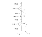
- 2 is a cross-sectional view taken along the line II shown in FIG.
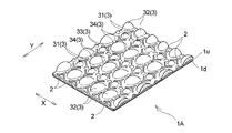
- FIG. 3 is a perspective view showing the fiber sheet according to the first embodiment of the present invention.
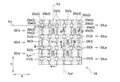
- FIG. 4 is a plan view showing the shape and arrangement pattern of embossed portions in the fiber sheet shown in FIG.
- FIG. 5 is an enlarged plan view showing the shape and arrangement pattern of the embossed portion in the middle convex portion shown in FIG.
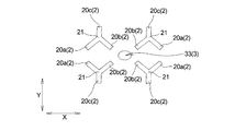
- FIG. 6 is an enlarged plan view showing the shape and arrangement pattern of the embossed portion in the high convex portion shown in FIG.
- FIG. 1 is the top view which looked at the sanitary napkin which is an absorbent article using the fiber sheet of this invention for the surface sheet from the surface sheet side.
- 2 is a cross-sectional view taken along the line II shown in FIG.
- FIG. 3 is a perspective view showing the fiber sheet according
- FIG. 7 is an enlarged plan view showing the shape and arrangement pattern of the embossed portion in the low convex portion shown in FIG.
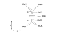
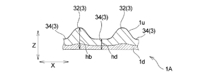
- FIG. 8 is an enlarged plan view showing the shape and arrangement pattern of the embossed portion in the columnar convex portion shown in FIG. 9 is a cross-sectional view taken along the line II-II shown in FIG. 10 is a cross-sectional view taken along line III-III shown in FIG. 11 is a cross-sectional view taken along line IV-IV shown in FIG. 12 is a cross-sectional view taken along line VV shown in FIG.
- FIG. 13 is a top view which shows the shape and arrangement pattern of the embossed part in the fiber sheet which is 2nd Embodiment of this invention.
- FIG. 13 is a top view which shows the shape and arrangement pattern of the embossed part in the fiber sheet which is 2nd Embodiment of this invention.
- FIG. 14 is a plan view showing the shape and arrangement pattern of embossed portions in a fiber sheet according to another embodiment of the present invention.
- FIG. 15 is a plan view showing the shape and arrangement pattern of embossed portions in a fiber sheet that is a comparative example of the fiber sheet of the present invention.
- the Y direction in the figure is the second direction and is the same direction as the machine direction (MD direction).
- the X direction in the figure is a first direction orthogonal to the second direction, and is the same direction as the direction (CD direction) orthogonal to the machine direction (MD direction).
- the Z direction in the figure is the thickness direction.
- the sanitary napkin 10 includes a top sheet (fiber sheet 1A) disposed on the skin contact surface side, a back sheet 12 disposed on the non-skin contact surface side, and a Y direction disposed between the two sheets 1A and 12.
- the long absorber 13 is provided.
- the sanitary napkin 10 is provided with a pair of side sheets 14 and 14 on both side portions 10s and 10s along the Y direction, and a pair of wing portions 15 and 15 extending outward in the X direction. ing. As shown in FIG.
- the sanitary napkin 10 is formed symmetrically with respect to a center line CL extending in the Y direction.
- the Y direction is the same as the product longitudinal direction
- the X direction is also the same as the product lateral direction.
- the “skin contact surface” is a surface disposed on the skin side of the wearer when worn, out of the front and back surfaces of each member such as the surface sheet (fiber sheet 1 ⁇ / b> A) constituting the sanitary napkin 10.
- the “non-skin contact surface” is a surface of the front and back surfaces of each member such as the surface sheet (fiber sheet 1A) that is directed to the side opposite to the wearer's skin when worn.
- the sanitary napkin 10 includes a top sheet (fiber sheet 1A), a back sheet 12, and an absorbent body 13 disposed between the sheets 1A and 12. It has an absorbent main body 11.
- the absorbent main body 11 includes a central part A, which is an area where the wing parts 15, 15 are located, and a front part disposed on the stomach side of the wearer from the central part A when the sanitary napkin 10 is worn.
- B and the sanitary napkin 10 are divided into a rear part C arranged on the back side of the wearer rather than the central part A when the sanitary napkin 10 is worn.
- the central part A of the absorbent main body 11 is usually disposed opposite to the excretion part (such as the vaginal opening) of the wearer.
- the wing part 15 is formed in the excretion facing area (area facing the excretion part of the wearer) of the absorbent main body 11.
- each of the top sheet (fiber sheet 1 ⁇ / b> A) and the back sheet 12 that forms the absorbent main body 11 covers the entire skin contact surface side and non-skin contact surface side of the absorber 13. And has an extending portion extending from the periphery of the absorber 13.
- the top sheet (fiber sheet 1 ⁇ / b> A) has a length in the X direction shorter than the length of the back sheet 12 in the X direction.
- each of the pair of side sheets 14 and 14 is on the skin contact surface side of the top sheet (fiber sheet 1A), and is the side along the Y direction of the top sheet (fiber sheet 1A).
- the sanitary napkin 10 As shown in FIGS. 1 and 2, the X-direction outwardly extending portion of the back sheet 12 and the X-direction outwardly extending portion of the side sheet 14 are bonded, fused, or the like.
- the wing portion 15 is formed by extending outward in the X direction at the central portion A more than the front portion B and the rear portion C. Adhesives are respectively applied to the width direction (X direction) center portion of the back sheet 12 of the sanitary napkin 10 and the non-skin facing surface of the extending portion of the back sheet 12 of the wing portion 15.
- a fixing portion 16 is formed for fixing the garment to underwear such as shorts.
- sheet 14 arrange
- a three-dimensional gather in which a portion having a predetermined width from the end portion is separated from the topsheet (fiber sheet 1A) may be formed.
- the sanitary napkin 10 has a round embossed groove (not shown) formed by integrally compressing the top sheet (fiber sheet 1A) and the absorbent body 13 extending in the Y direction, and rearward from the front portion B. It extends to part C.
- the embossed groove (not shown) is formed in a single round shape connected to the front part B, the side parts 10s, 10s and the rear part C of the sanitary napkin 10.
- the embossed grooves (not shown) are formed by compressing the top sheet (fiber sheet 1A) and the absorber 13 from the skin contact surface side with or without heat.
- the fiber sheet of the present invention is a sheet having a heat-shrinkable fiber layer 1d containing heat-shrinkable fibers and a plurality of embossed portions 2 as shown in FIG. More specifically, the fiber sheet 1A used for the top sheet of the sanitary napkin 10 has a heat-shrinkable fiber layer 1d, and further comprises non-heat-shrinkable fibers made of non-heat-shrinkable fibers laminated on the heat-shrinkable fiber layer 1d. It has a layer 1u. In the fiber sheet 1A, the non-heat-shrinkable fiber layer 1u is disposed on the skin contact surface side, and the heat-shrinkable fiber layer 1d is disposed on the non-skin contact surface side.
- the heat-shrinkable fiber layer 1d and the non-heat-shrinkable fiber layer 1u of the fiber sheet 1A are intermittently joined by a plurality of embossed portions 2. Specifically, in the fiber sheet 1A, the heat-shrinkable fiber layer 1d and the non-heat-shrinkable fiber layer 1u are partially bonded by a plurality of regularly arranged embossed portions 2 and bonded to each other.
- the heat-shrinkable fibers of the heat-shrinkable fiber layer 1d on the contact surface side are formed by heat-shrinking. As shown in FIG.
- the fiber sheet 1 ⁇ / b> A has a plurality of concave portions recessed by the embossed portion 2 embossed from the skin contact surface side of the non-heat-shrinkable fiber layer 1 u and a plurality of convex portions on the non-embossed non-embossed portion. Part 3 is formed.
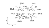
- each of the plurality of embossed portions 2 has a shape in which three rod-like bodies 20 a, 20 b, and 20 c extend from a center point 21 in a plan view, and is a so-called “Y-shaped” shape. It is.
- the three rod-like bodies 20a and 20b in each embossed portion 2 have the same length from the intersection 21 in the fiber sheet 1A. The length is shorter than the other two rod-like bodies 20a and 20b.
- the rod-like body 20c among the three rod-like bodies 20a, 20b, and 20c is arranged in parallel to the Y direction in the fiber sheet 1A.
- Each embossed part 2 is provided separately in the X direction and the Y direction at regular intervals and separately.
- the embossed portions 2 and 2 adjacent to each other in the X direction are arranged so as to be symmetric with respect to a virtual bisector ILy (see FIG. 6) extending in parallel to the Y direction in plan view.
- the embossed portions 2 and 2 adjacent to each other in the Y direction are arranged so as to be symmetric with respect to a virtual bisector ILx (see FIG. 6) extending in parallel with the X direction in plan view.
- Each embossed portion 2 has a density of 1 piece / cm 2 or more, preferably 2 pieces / cm 2 or more, from the viewpoint of enhancing the drawability and diffusibility of the liquid in the fiber sheet 1A and maintaining good touch, and 32 pieces / cm 2 or less, preferably 16 pieces / cm 2 or less, more specifically, preferably 1 piece / cm 2 or more and 32 pieces / cm 2 or less, and preferably 2 pieces / cm 2 or more and 16 pieces / cm 2. More preferably, it is 2 or less.
- the intersection angle ⁇ 1 (see FIG. 6) between the rod-shaped body 20a and the rod-shaped body 20b is 10 from the viewpoint of reducing the contact area with the skin in the fiber sheet 1A, maintaining a good touch, and improving the visual impression. Or more, preferably 50 ° or more, and 170 ° or less, preferably 130 ° or less, more specifically 10 ° or more and 170 ° or less, and more preferably 50 ° or more and 130 ° or less. preferable.
- the intersection angle ⁇ 1 is 110 °.
- the intersection angle ⁇ 2 (see FIG.
- ⁇ 2 is 95 ° or more, preferably 120 ° or more, and 175 ° or less, preferably 150 ° or less, more specifically 95 ° or more and 175 ° or less, and preferably 120 ° or more and 150 ° or less. More preferably it is.
- the intersection angle ⁇ 2 ( ⁇ 3) is 125 °.
- the sum of the intersection angle ⁇ 1, the intersection angle ⁇ 2, and the intersection angle ⁇ 3 is 360 °.
- the two embossed portions 2, 2 arranged symmetrically with respect to the virtual bisector ILy adjacent to each other in the X direction have a rod shape that one embossed portion 2 has.
- the rod-like body 20b of the body 20a and the other embossed portion 2 extends in an inclined manner in the same direction as viewed in plan.
- the fiber sheet 1A as shown in FIG.
- the rod-shaped body 20a and the rod-shaped body 20b of the other embossed portion 2 extend inclining in the same direction as viewed in plan.
- the two long rod-like bodies 20a, 20b out of the three rod-like bodies 20a, 20b, 20c are improved in the drawability and diffusibility of the liquid in the fiber sheet, and from the viewpoint of emotionality
- the length is 0.5 mm or more, preferably 0.7 mm or more and 5.0 mm or less, preferably 4.0 mm or less, more specifically 0.5 mm or more and 5.0 mm or less. More preferably, it is 0.7 mm or more and 4.0 mm or less.
- the short rod-shaped body 20c is 0.2 mm or more, preferably 0.4 mm or more, and 4.8 mm or less from the viewpoint of improving the drawability and diffusibility of the liquid in the fiber sheet and improving the visual impression.
- the thickness is preferably 4.5 mm or less, more specifically 0.2 mm or more and 4.8 mm or less, and further preferably 0.4 mm or more and 4.5 mm or less.
- Each embossed part 2 has an area of one embossed part 2 of 1 mm 2 or more, preferably 1.5 mm 2 from the viewpoint of enhancing the drawability and diffusibility of the liquid in the fiber sheet 1A while maintaining a good touch. As described above, it is preferably 15 mm 2 or less, preferably 12 mm 2 or less, more specifically, 1 mm 2 or more and 15 mm 2 or less, more preferably 1.5 mm 2 or more and 12 mm 2 or less.
- the fiber sheet of the present invention has a hemispherical high convex portion 32 having the highest height, a hemispherical low convex portion 33 having the lowest height, and a height higher than the high convex portion 32. And a plurality of hemispherical middle convex portions 31 having a height lower than that of the low convex portion 33.
- the convex portion 3 of the fiber sheet 1 ⁇ / b> A has a hemispherical high convex portion 32, a hemispherical low convex portion 33, a hemispherical middle convex portion 31, and a semispherical portion. It consists of a columnar columnar convex portion 34, and a plurality of high convex portions 32, low convex portions 33, middle convex portions 31, and columnar convex portions 34 are arranged.
- a plurality of middle convex portions 31 are arranged at intervals in the first direction (X direction), and a plurality of middle convex portions 31 are arranged in the first direction (X direction).
- a plurality of first convex row 30La are arranged at intervals in the second direction (Y direction).
- Each middle convex portion 31 is surrounded by two embossed portions 2 and 2.
- the middle convex portion 31 of the convex portion 3 has a rod-like body 20a of each of the two embossed portions 2 and 2 adjacent to each other in the Y direction when the fiber sheet 1A is viewed in plan view. , 20b are formed in regions facing each other.
- the middle convex portion 31 is regularly arranged in the X direction and the Y direction, and is surrounded by the long rod-like bodies 20 a and 20 b of the two embossed portions 2 and 2.
- the three-dimensional dome structure has a hemispherical bulge on the skin contact surface side.
- a plurality of high convex portions 32 are arranged at intervals in the first direction (X direction), and a plurality of high convex portions 32 are formed in the first direction (X direction).
- the second convex row 30Lb is arranged alternately with the first convex row 30La in the second direction (Y direction), and each high convex portion 32 is surrounded by four middle convex portions 31. Yes.
- Each high convex portion 32 is surrounded by four embossed portions.
- the high convex portion 32 of the convex portion 3 includes two embossed portions 2 adjacent to each other in the X direction when the fiber sheet 1 ⁇ / b> A is viewed in plan view, and the two embossed portions.
- Each of the four embossed portions 2 made up of two embossed portions 2 adjacent to each other in the Y direction is formed in a region where the long rod-shaped body 20b and the short rod-shaped body 20c face each other.
- the high convex part 32 of the convex part 3 is formed in the area
- the high convex portions 32 are regularly arranged in the X direction and the Y direction, and the rod-like bodies 20 a and 20 c or the rod-like bodies 20 b and 20 c of each of the four embossed portions 2.
- the solid dome structure is long in the Y direction and is hemispherically raised on the skin contact surface side.
- each of the plurality of low convex portions 33 includes a high convex portion 32 between the middle convex portions 31 adjacent in the first direction (X direction) and adjacent in the second direction (Y direction). It is arranged every time. As shown in FIG. 7, each low convex portion 33 is located at a position where the ends of the long rod-shaped bodies 20 a in the four embossed portions 2, or the tips of the long rod-shaped bodies 20 b in the four embossed portions 2 face each other. It is arranged. As shown in FIG.
- the long bar-shaped body 20a of each of the four embossed parts 2 or the long bar-shaped body 20b of each of the four embossed parts 2 arranged in this way has an intersection angle 45 in the X direction and the Y direction. It extends along a straight line connecting the intersections 21 and 21 of the two embossed portions 2 and 2 adjacent to each other in the direction intersecting at an angle.
- the low protrusions 33 are regularly arranged in the X direction and the Y direction, and the tips of the rod-like bodies 20 a or the tips of the rod-like bodies 20 b of the four embossed portions 2. It is a solid dome structure surrounded by, and is hemispherically raised to the skin contact surface side.
- the low convex part 33 exists between the closest middle convex parts 31, and the first convex part row 30La is formed, so that the drawability of the liquid is improved and the good touch is maintained. There is an effect.
- the plurality of semi-cylindrical columnar convex portions 34 are adjacent to each other between the high convex portions 32 adjacent to each other in the first direction (X direction) and in the second direction (Y direction). It is arranged at every interval between the middle convex portions 32.
- each columnar convex portion 34 is formed in a region where the tips of the short rod-like bodies 20 c of the two embossed portions 2 adjacent in the Y direction face each other.
- the columnar protrusions 34 are regularly arranged in the X direction and the Y direction, and in the vertical direction between the tips of the short rod-like bodies 20 c of the two embossed parts 2.
- the semicircular bulge When viewed in cross-section in the longitudinal (Y direction) cross section, it bulges in a semicircular shape on the skin contact surface side, the semicircular bulge extends in the first direction (X direction), and is a semicylindrical shape that is long in the X direction Is formed.
- the middle convex parts 31 adjacent to a 2nd direction (Y direction) will be the 1st direction (X direction).
- Y direction the middle convex parts 31 adjacent to a 2nd direction
- X direction the 1st direction
- the virtual bisector ILx1 passes through an intermediate point between the middle convex portions 31 adjacent to each other in the second direction (Y direction), and a plurality of bisectors ILx1 arranged at intervals in the first direction (X direction). It is arranged over the columnar protrusions 34.
- the pair of embossed portions 2, 2 and the pair of embossed portions 2, 2 are arranged in the Y direction.
- a columnar convex portion 34 disposed between them is disposed.
- the high convex portion 32 constituting the convex portion 3 of the fiber sheet 1A will be described in more detail.
- the high convex portions 32 adjacent to each other in the first direction (X direction) are a pair of embossed portions. 2 and 2 are arranged.
- An imaginary bisector ILy1 extending in parallel with the second direction (Y direction) passing through the intermediate point between the high convex portions 32 adjacent to each other in the first direction (X direction) is in the second direction (Y direction). It passes through the midpoints of the plurality of columnar convex portions 34 arranged at intervals, and is arranged over the rod-shaped bodies 20c in the plurality of embossed portions 2 arranged at intervals in the second direction (Y direction). .
- the pair of embossed portions 2, 2 and the pair of embossed portions 2, 2 A columnar convex portion 34 disposed between them is disposed.
- a fiber density gradient is imparted in the fiber sheet 1A to increase the drawability of the liquid, and the effect of reducing stickiness and stuffiness is achieved.
- the height ha (see FIG. 10) at the apex of the middle convex portion 31 is 0.5 mm or more, preferably 1.0 mm or more, from the viewpoint of maintaining a good feel of the fiber sheet and reinforcing the density gradient of the fiber. 5.0 mm or less, preferably 3.0 mm or less, more specifically 0.5 mm or more and 5.0 mm or less, more preferably 1.0 mm or more and 3.0 mm or less.
- the height ha of the middle convex portion 31 is also the height at the position corresponding to the center of gravity of the region where the rod-like bodies 20a, 20b of the two embossed portions 2 adjacent in the Y direction face each other.
- the height ha is measured in the same manner as the fiber density ratio (1) of the fiber sheet 1A described later.
- the rising angle ⁇ 4 (see FIG. 12) from the bottom surface of the middle convex portion 31 is a smooth absorber after menstrual blood is temporarily stocked. From the viewpoint of facilitating the drawing of menstrual blood to 13, it is preferably 50 ° or more, preferably 55 ° or more, and 65 ° or less, preferably 60 ° or less, more specifically 50 ° or more and 65 ° or less. More preferably, the angle is 55 ° or more and 60 ° or less.
- the ridge angle ⁇ 4 is measured simultaneously with the measurement of the height ha.
- the height hb (see FIG. 9) at the apex of the high convex portion 32 is 1.0 mm or more, preferably from the viewpoint of enhancing the good feel of the fiber sheet and enhancing the density of the fiber to enhance the drawability of the liquid. Is 1.5 mm or more and 7.0 mm or less, preferably 5.0 mm or less, more specifically 1.0 mm or more and 7.0 mm or less, more preferably 1.5 mm or more and 5.0 mm or less. More preferably.
- the height hb of the high convex portion 32 is a region where the rod-like bodies 20b, 20c of the four embossed portions 2 face each other, or a region where the rod-like bodies 20a, 20c of the four embossed portions 2 face each other.
- the height hb is measured in the same manner as the fiber density ratio (1) of the fiber sheet 1A described later.
- the bulging angle from the bottom surface of the high convex portion 32 is from the viewpoint of making it difficult to leave menstrual blood at a portion that touches the skin even during a large amount of menstrual blood. 70 ° or more, preferably 75 ° or more, and 90 ° or less, preferably 85 ° or less, more specifically 70 ° or more and 90 ° or less, and more preferably 75 ° or more and 85 ° or less. Is more preferable.
- the elevation angle is measured simultaneously with the measurement of the height hb.
- the height hc (see FIG. 9) at the apex of the low convex portion 33 is 0.4 mm or more, preferably from the viewpoint of enhancing the good feel of the fiber sheet and enhancing the density of the fiber to enhance the drawability of the liquid. Is 0.8 mm or more and 4.5 mm or less, preferably 2.5 mm or less, more specifically 0.4 mm or more and 4.5 mm or less, preferably 0.8 mm or more and 2.5 mm or less. More preferably.
- the height hc of the low convex portion 33 is a position corresponding to the center of gravity of the region where the tips of the rod-shaped bodies 20a in each of the four embossed portions 2 or the tips of the rod-shaped bodies 20b in each of the four embossed portions 2 face each other. It is also the height of.
- the height hc is measured in the same manner as the fiber density ratio (1) of the fiber sheet 1A described later.
- the rising angle from the bottom surface of the low convex portion 33 is from the viewpoint of making it difficult to leave menstrual blood at a portion that touches the skin even during a large amount of menstrual blood.
- the elevation angle is measured simultaneously with the measurement of the height hc.
- the height hd (see FIG. 12) at the apex of the columnar convex portion 34 is preferably 0.4 mm or more, from the viewpoint of enhancing the good feel of the fiber sheet and enhancing the density gradient of the fiber to enhance the drawability of the liquid. Is 0.8 mm or more and 4.5 mm or less, preferably 2.5 mm or less, more specifically 0.4 mm or more and 4.5 mm or less, preferably 0.8 mm or more and 2.5 mm or less. More preferably. As described above, in the fiber sheet 1 ⁇ / b> A, the height hd at the apex of the columnar protrusion 34 is substantially the same as the height hc of the low protrusion 33.
- the height hd of the columnar convex portion 34 is also the height at the position corresponding to the center of gravity of the region where the rod-like bodies 20c, 20c of the two embossed portions 2 adjacent in the Y direction face each other.
- the height hd is measured in the same manner as the fiber density ratio (1) of the fiber sheet 1A described later.
- the interval between the embossed portions 2 adjacent in the first direction (X direction), in other words, the interval between the tips of the rod-like bodies 20a, 20b in each of the four embossed portions 2 surrounding the high convex portion 32 or the low convex portion 33 is From the viewpoint of enhancing the drawability and diffusibility of the liquid in the fiber sheet and improving the appearance and improving the emotion, 0.5 mm or more, preferably 1.0 mm or more, and 5.0 mm or less, preferably 4.0 mm or less, more specifically 0.5 mm or more and 5.0 mm or less is preferable, and 1.0 mm or more and 4.0 mm or less is still more preferable.
- the thickness is 0.5 mm or more, preferably 1.0 mm or more, and 5.0 mm or less, preferably 4.0 mm or less, more specifically 0.5 mm or more and 5.0 mm or less. It is preferable that it is 1.0 mm or more and 4.0 mm or less.
- the thickness is 0.5 mm or more, preferably 1.0 mm or more, and 5.0 mm or less, preferably 4.0 mm or less, more specifically 0.5 mm or more and 5.0 mm or less. It is preferable that it is 1.0 mm or more and 4.0 mm or less.
- the convex portion 3 will be described in further detail. As shown in FIG. 3, the height increases in the order of the high convex portion 32 of the three-dimensional dome structure, the middle convex portion 31 of the three-dimensional dome structure, and the low convex portion 33 of the three-dimensional dome structure. In that order, the bottom area of each convex portion also increases.
- the constituent fibers of the fiber sheet 1A are consolidated, and the height (thickness) of the topsheet 1 is the lowest (thin) compared to the unembossed portion. It has become. That is, the fiber density of the recessed part by the embossed part 2 is higher than the part which is not the embossed part 2, and is the highest in the fiber sheet 1A.
- the constituent fibers may be melted and solidified to form a film.
- the high convex portion 32 of the three-dimensional dome structure has a fiber density lower than the fiber density of each of the middle convex portion 31 and the low convex portion 33 of the three-dimensional dome structure. Is the lowest among the fiber sheets 1A.
- the middle convex portion 31 of the three-dimensional dome structure has a fiber density lower than the fiber density of the low convex portion 33 of the three-dimensional dome structure, and the middle convex portion 31 particularly at the apex (reference point of the height ha). Is the lowest of all.
- the low convex portion 33 of the three-dimensional dome structure has the lowest fiber density among the low convex portions 33 at the apex (the reference point of the height hc).
- the fiber density at the apex of the high convex portion 32 is the fiber density at the apex of the intermediate convex portion 31 (reference point of height ha) and the apex (height of the low convex portion 33).
- the fiber density at the vertex of the middle convex portion 31 is lower than the fiber density at the reference point of hc, and the fiber density at the vertex of the low convex portion 33 (reference point of the height hc). It is lower than the density.
- the ratio (db / da) of the fiber density db at the vertex (reference point of height hb) of the high convex portion 32 to the fiber density da at the vertex (reference point of height ha) of the middle convex portion 31 was excreted. From the viewpoint of enhancing the drawing-in property of the body fluid, 1.2 times or more, preferably 1.5 times or more, and 3.0 times or less, preferably 2.5 times or less, more specifically 1.2 times. The ratio is preferably 3.0 times or more and more preferably 1.5 times or more and 2.5 times or less.
- the ratio (db / dc) of the fiber density db at the apex of the high convex portion 32 (reference point of height hb) to the fiber density dc at the apex of the low convex portion 33 (reference point of height hc) was excreted. From the viewpoint of enhancing the drawing-in property of the body fluid, 1.2 times or more, preferably 1.5 times or more, and 3.0 times or less, preferably 2.5 times or less, more specifically 1.2 times. The ratio is preferably 3.0 times or more and more preferably 1.5 times or more and 2.5 times or less.
- the ratio (da / dc) of the fiber density da at the vertex (reference point of height ha) of the middle convex portion 31 to the fiber density dc at the vertex (reference point of height hc) of the low convex portion 33 was excreted. From the viewpoint of enhancing the drawing-in property of the body fluid, 1.2 times or more, preferably 1.5 times or more, and 3.0 times or less, preferably 2.5 times or less, more specifically 1.2 times. The ratio is preferably 3.0 times or more and more preferably 1.5 times or more and 2.5 times or less.
- the ratio of the fiber density of the fiber sheet 1A can be measured using one of the two methods (1) and (2) described below. (1) When the basis weight of the fiber sheet 1A is substantially uniform (uniform) (or can be determined to be substantially uniform), the height (thickness) of the cut surface of the fiber sheet 1A is measured. (2) When the basis weight of the fiber sheet 1A is non-uniform (or can be determined to be non-uniform), the average distance between fibers on the cut surface of the fiber sheet 1A is measured.
- the determination as to whether the basis weight of the fiber sheet 1A is substantially uniform is performed as follows.
- 10 or more cut samples having a size of 10 cm in the Y direction and 10 cm in the X direction are taken out from the fiber sheet 1A and each basis weight is measured, the triple value (3 ⁇ ) of the standard deviation ⁇ is within 10% of the average ⁇ . If there is no fiber unevenness on the appearance, it is judged to be substantially uniform. However, it is preferable to make a comprehensive judgment in consideration of various factors such as the composition being different in a minute region.
- a sample for measuring the high convex portion 32 is created by cutting along a straight line passing through the center of gravity (vertex) of the high convex portion 32 of the solid dome structure and the two embossed portions 2 at both ends.
- a sample for measuring the middle convex portion 31 is created by cutting along a straight line passing through the center of gravity (vertex) of the middle convex portion 31 of the three-dimensional dome structure and the two embossed portions 2 at both ends.
- a sample for measuring the low convex portion 33 is created by cutting along a straight line passing through the center of gravity (vertex) of the low convex portion 33 of the three-dimensional dome structure and the two embossed portions 2 at both ends. At this time, care should be taken not to cause a decrease in the height of each measurement sample due to cutting.
- each measurement sample obtained was measured using an electron microscope JCM-5100 manufactured by JEOL Ltd. under the conditions of a sputtering time of 30 seconds (Pt) and an acceleration voltage of 10 KV. At least one of the embossed portions 2 is photographed, or a situation where the embossed portions 2 can be understood by combining a plurality of images is measured, and the height (thickness) of each measurement sample is measured from the photographed images. Note that the image measurement may be performed using either a printed matter or a PC screen.
- the height hb (thickness) of the central portion of the sample for measuring the high convex portion 32 is divided by the height ha (thickness) of the central portion of the sample for measuring the middle convex portion 31 to obtain the density.
- the ratio is (db / da).
- the density ratio (db / dc) is obtained by dividing the height hb (thickness) of the central portion of the sample for measuring the high convex portion 32 by the height hc (thickness) of the central portion of the sample for measuring the low convex portion 33.
- the ratio of the density (da / dc) by dividing the height ha (thickness) of the central portion of the sample for measuring the middle convex portion 31 by the height hc (thickness) of the central portion of the sample for measuring the low convex portion 33.
- the cross section is measured in the same manner as in the method (1).
- the cross section of each measurement sample is photographed at an enlargement magnification of 500 to 1000 times.
- the image analysis device (NEWQUABE ver. 4.20 manufactured by NEXT) Is used to find the distance between the nearest centers of gravity of the fibers.
- measurement is performed almost entirely in the height (thickness) direction, and the closest distance between the centers of gravity is not caused to overlap.
- the distance ratio between the nearest centroids at the center of the sample for measuring the high convex portion 32 is divided by the distance between the nearest centroids at the center of the sample for measuring the middle convex portion 31 ( In addition, the distance ratio between the nearest centroids at the center of the sample for measuring the high convex portion 32 is divided by the distance between the nearest centroids at the center of the sample for measuring the low convex portion 33.
- the distance ratio between the nearest centroids of the center portion of the sample for determining the middle convex portion 31 is divided by the distance between the nearest centroids of the center portion of the sample for measuring the low convex portion 33. (Da / dc).
- a material for forming the sanitary napkin 10 using the above-described fiber sheet of the present invention as a top sheet will be described.
- the forming material of the fiber sheet 1A used for the top sheet will be described.
- the non-heat-shrinkable fiber layer 1u made of non-heat-shrinkable fibers for example, a web formed by a card method or a bulky nonwoven fabric is preferably used.
- a bulky nonwoven fabric from the viewpoint that it is possible to give the fiber sheet 1A a desired density gradient, and it is possible to bring a good texture to the fiber sheet 1A, an air-through nonwoven fabric, an airlaid nonwoven fabric, A resin bond nonwoven fabric is preferably used.
- the web formed by the card method is a fiber assembly in a state before being made into a nonwoven fabric. That is, a fiber assembly in a state where fibers are extremely loosely entangled in a state where a post-processing applied to a card web used for manufacturing a nonwoven fabric, for example, a heat-sealing process by an air-through method or a calendar method is not performed. It is the body.
- a web formed by the card method is used as the non-heat-shrinkable fiber layer 1u, the non-heat-shrinkable fiber layer 1u and the heat-shrinkable fiber layer 1d are joined simultaneously or after being joined, and then the non-heat-shrinkable fiber layer 1u. Heat-bond the fibers inside.
- non-heat-shrinkable fiber that is a constituent fiber of the non-heat-shrinkable fiber layer 1u, if it is a fiber that does not substantially have heat-shrinkability or has a higher heat-shrink temperature than the lower layer (heat-shrinkable fiber layer).
- the basis weight of the non-heat-shrinkable fiber layer 1u is 10 g / m 2 or more, preferably 15 g / m 2 or more, and 50 g / m 2 from the viewpoint of forming a sufficient density gradient and improving the touch of the surface sheet 1.
- m 2 or less preferably 40 g / m 2 or less, more specifically 10 g / m 2 or more and 50 g / m 2 or less, more preferably 15 g / m 2 or more and 40 g / m 2 or less.
- heat-shrinkable fiber layer 1d containing heat-shrinkable fibers a web formed by a card method or a non-woven fabric having heat-shrinkability can be used.
- the heat-shrinkable fibers of the constituent fibers of the heat-shrinkable fiber layer 1d those made of a thermoplastic polymer material and having heat-shrinkability are preferably used. Examples of such fibers include latently crimpable fibers.
- the latent crimpable fiber can be handled in the same manner as a conventional nonwoven fabric fiber before being heated, and has a property that a helical crimp is developed and contracted by heating at a predetermined temperature. Fiber.
- the content ratio of the heat-shrinkable fiber in the heat-shrinkable fiber layer 1d is preferably 40% by mass or more and 100% by mass or less.
- the latent crimpable fiber which is a heat-shrinkable fiber
- the latent crimpable fiber is composed of, for example, an eccentric core-sheath type or side-by-side type composite fiber composed of two types of thermoplastic polymer materials having different shrinkage rates. Examples thereof include those described in JP-A-9-296325 and Japanese Patent No. 2759331.
- the heat-shrinkable fiber layer 1d includes, for example, such latently crimpable fibers, and simultaneously or after heat fusion with the non-heat-shrinkable fiber layer 1u, causes the fibers to crimp. Can be shrunk.
- the basis weight of the heat-shrinkable fiber layer 1d is 10 g / m 2 or more, preferably 15 g / m 2 or more, and 50 g / m 2 or less, preferably 40 g / m 2 or less, more specifically 10 g / m 2. It is preferably 50 g / m 2 or more, more preferably 15 g / m 2 or more and 40 g / m 2 or less.
- a fiber sheet 1A according to an embodiment of the present invention has, for example, a non-heat-shrinkable fiber layer 1u containing non-heat-shrinkable fibers as an upper layer and a heat-shrinkable fiber layer 1d made of heat-shrinkable fibers before shrinking as a lower layer.
- a non-heat-shrinkable fiber layer 1u containing non-heat-shrinkable fibers as an upper layer
- a heat-shrinkable fiber layer 1d made of heat-shrinkable fibers before shrinking as a lower layer.
- non-heat-shrinkable fiber layer 1u and the heat-shrinkable fiber layer 1d are intermittently bonded and integrated by the embossed portion 2, when the heat-shrinkable fiber layer 1d is heat-shrinked, the non-heat-shrinkable fiber layer 1u is entangled. Distortion occurs when trying to shrink. This distortion protrudes in a convex shape toward the non-heat-shrinkable fiber layer 1u, and a plurality of three-dimensional dome-shaped convex portions 3 are formed.
- the bonding (heat fusion) by the embossed part 2 is, for example, a plurality of substantially Y to correspond to the arrangement of the embossed part 2 in a shape in which the three rod-like bodies 20a, 20b, 20c extend from the center point 21.
- An embossed surface in which letter-shaped embossed pins are arranged in a predetermined pattern is disposed on the non-heat-shrinkable fiber layer 1u side in the laminate of the non-heat-shrinkable fiber layer 1u and the heat-shrinkable fiber layer 1d.
- the non-heat-shrinkable fiber layer 1u and the heat-shrinkable fiber layer 1d are melted at the portions heat-pressed by the embossed spins.
- the heat shrinkage of the heat-shrinkable fiber layer 1d is, for example, that the heat-shrinkable fiber layer 1d is composed of only one or more kinds of heat-shrinkable fibers, or one or more kinds of heat-shrinkable in the heat-shrinkable fiber layer 1d.
- the fibers are contained, and the non-heat-shrinkable fiber layer 1u and the heat-shrinkable fiber layer 1d are bonded together or after the non-heat-shrinkable fiber layer 1u and the heat-shrinkable fiber layer 1d are bonded together, the heat-shrinkable fiber layer 1d Is carried out by heat treatment.
- the area surrounded by the rod-like bodies 20a and 20c or the rod-like bodies 20b and 20c of the four embossed portions 2 is the widest area as shown in FIG. It is difficult to be restrained by the embossed portion 2, and is easily raised into a three-dimensional dome structure, resulting in a high convex portion 32. Further, as shown in FIG. 7, the regions where the tips of the rod-like bodies 20a in each of the four embossed portions 2 or the tips of the rod-like bodies 20b of each of the four embossed portions 2 face each other are narrow.
- the three-dimensional dome-structured bulge is suppressed by the four embossed portions 2, so that the low convex portion 33 having the lowest height is obtained.
- the region where the rod-like bodies 20 a and 20 b of the two embossed portions 2 adjacent in the Y direction face each other is narrower than the region that becomes the high convex portion 32, but becomes the low convex portion 33. Since it is wider than the region, the three-dimensional dome structure-like bulge is slightly suppressed, and the middle convex portion 31 is lower than the high convex portion 32 and higher than the low convex portion 33.
- the fiber sheet 1 ⁇ / b> A has a plurality of concave portions (embossed portions 2) and a plurality of convex portions 3 (a plurality of high convex portions 32 and a plurality of middle convex portions 31 over the entire area.
- a plurality of low convex portions 33 and a plurality of columnar convex portions 34) are formed.
- the fiber sheet 1A formed by bonding the non-heat-shrinkable fiber layer 1u and the heat-shrinkable fiber layer 1d by the method described above has a basis weight of 20 g / m 2 or more, preferably 35 g / m 2 or more, and 100 g / m m 2 or less, preferably 80 g / m 2 or less, more specifically 20 g / m 2 or more and 100 g / m 2 or less, more preferably 35 g / m 2 or more and 80 g / m 2 or less. .
- the absorber 13, and the side sheet 14 that constitute the absorbent main body 11 are used without particular limitation. be able to.
- the back sheet 12 a liquid-impermeable or water-repellent resin film, a laminate of a resin film and a nonwoven fabric, or the like can be used.
- the absorbent body 13 an aggregate of fibers such as pulp fibers (which may be a nonwoven fabric) or an absorbent core in which water-absorbing polymer particles are held by the absorbent core 13 is made of water-permeable thin paper or nonwoven fabric. Those coated with a core wrap sheet can be used.
- the side sheet 14 the same sheet as the back sheet 3 can be used.
- adhesive means used for absorbent articles such as disposable diapers
- fusion means such as heat embossing, ultrasonic embossing, high frequency embossing, etc. Is used.
- the fiber sheet 1 ⁇ / b> A includes a plurality of high convex portions 32 having the highest height, a plurality of middle convex portions 31 having a height lower than that of the high convex portions 32, and a plurality of low protrusions having the lowest height. And a convex portion 33. Therefore, when the sanitary napkin 10 is worn, the high convex portion 32 comes into contact with the skin, but the middle convex portion 31 and the low convex portion 33 arranged between the high convex portions 32 are hard to come into contact with the skin.
- 1 A of fiber sheets of 1st Embodiment can further reduce a contact area with a wearer's skin, and can reduce the damage to skin.
- the contact area between the fiber sheet 1A and the wearer's skin is preferably 45% or less, particularly 42% or less, for the above reasons, and the lower limit is preferably 25% or more, particularly preferably 30% or more.
- the fiber sheet 1 ⁇ / b> A has a plurality of two kinds of middle convex portions 31 and low convex portions 33 each having a height lower than that of the high convex portion 32. Accordingly, when the sanitary napkin 10 is worn, even if pressure is applied and the high convex portion 32 is crushed and the middle convex portion 31 comes into contact with the skin, the lowest low convex portion 33 is unlikely to come into contact with the skin. . Therefore, when the fiber sheet 1A is used as the top sheet, even when pressure is applied when the sanitary napkin 10 is worn, the contact area with the wearer's skin can be reduced, and the sticky feeling can be reduced. .
- each high convex portion 32 is surrounded by four middle convex portions 31, and each low convex portion 33 is adjacent to the middle convex portion in the X direction. This is particularly noticeable in the shape arranged between the portions 31 and between the high convex portions 32 adjacent in the Y direction.
- the absorption performance of body fluid can improve the feeling of stickiness and stuffiness and reduce the damage to the skin.
- the fiber sheet 1A is formed by arranging the non-heat-shrinkable fiber layer 1u on the skin contact surface side and the heat-shrinkable fiber layer 1d on the non-skin contact surface side. . Therefore, the excreted body fluid is drawn from the skin contact surface side to the non-skin contact surface side by the capillary force, and is quickly transferred to produce a sag reduction effect.
- the fiber sheet 1A has a large convex portion 32, a middle convex portion 31, and a small convex portion 33, each having a different apex height, which are regularly arranged. Play.
- fiber sheet 1B a fiber sheet (hereinafter also referred to as “fiber sheet 1B”) as a second embodiment of the fiber sheet of the present invention will be described with reference to FIG.
- fiber sheet 1B of 2nd Embodiment a different point from the fiber sheet 1A of 1st Embodiment is demonstrated.
- the points that are not particularly described are the same as those of the fiber sheet 14A, and the description of the fiber sheet 1A is appropriately applied.
- the three rod-like bodies 20a, 20b, 20c have the same length from the intersection 21, and are formed in the same size. They are formed in the same rectangular shape in plan view.
- the rod-like bodies 20a, 20b, 20c have a length of 0.5 mm or more, preferably 0.7 mm or more, from the viewpoint of enhancing the drawability and diffusibility of the liquid in the fiber sheet 1A and enhancing the appearance impression.
- each middle convex portion 31 is surrounded by two long rod-like bodies 20a and 20b in the two embossed portions 2, respectively.
- the middle convex portion 31 of the convex portion 3 is a long bar-like body of each of the two embossed portions 2 and 2 adjacent to each other in the Y direction when the fiber sheet 1B is viewed in plan view.
- 20a and 20b are formed in a region where each other faces each other.
- each high convex portion 32 is surrounded by one rod-like body 20a, 20b and one rod-like body 20c in each of the four embossed portions 2.
- the high convex portion 32 of the convex portion 3 includes two embossed portions 2 adjacent to each other in the X direction when the fiber sheet 1 ⁇ / b> B is viewed in plan view, and the two embossed portions.
- Each of the four embossed portions 2 formed of two embossed portions 2 adjacent to each other in the Y direction is formed in a region where the rod-shaped bodies 20b and the rod-shaped bodies 20c face each other.
- the high convex part 32 of the convex part 3 is formed in the area
- each low convex part 33 is distribute
- each of the low convex portions 33 is provided between the tips of the rod-like bodies 20 a in each of the four embossed portions 2 or between the tips of the rod-like bodies 20 b in each of the four embossed portions 2.
- the lengths of the three rod-like bodies 20a, 20b, 20c are the same as each other, and the rod-like bodies 20a, 20c or the rod-like shapes of the four embossed portions 2 are respectively. Since the region surrounded by the bodies 20b and 20c is elongated in the Y direction, the high convex portion 32 has a three-dimensional dome structure that is long in the Y direction due to heat shrinkage, and is hemispherically raised in the skin contact surface side and long in the Y direction. It is formed in a shape.
- the effect at the time of using the fiber sheet 1B of 2nd Embodiment of this invention mentioned above as a surface sheet of a sanitary napkin is demonstrated.
- a different point from the effect of the fiber sheet 1A is demonstrated.
- the point which is not demonstrated in particular is the same as the effect of the fiber sheet 1A, and the description of the effect of the fiber sheet 1A is appropriately applied.
- the forming material of the fiber sheet 1B it is the same as that of the forming material of the fiber sheet 1A.
- the fiber sheet 1 ⁇ / b> B is formed such that the high convex portion 32 of the three-dimensional dome structure, the middle convex portion 31 of the three-dimensional dome structure, and the low convex portion 33 of the three-dimensional dome structure are all raised in a hemispherical shape.
- the high convex portion 32 is formed in a hemispherical shape that is long in the Y direction, it has an effect of maintaining a good touch on the fiber sheet.
- the fiber sheet of the present invention is not limited to the fiber sheet 1A of the first embodiment and the fiber sheet 1B of the second embodiment, and can be appropriately changed. Moreover, each component in the fiber sheet 1A and the fiber sheet 1B described above can be appropriately combined and implemented within a range that does not impair the gist of the present invention.
- the above-described fiber sheets 1A and 1B have a two-layer structure formed by disposing the non-heat-shrinkable fiber layer 1u on the skin contact surface side and the heat-shrinkable fiber layer 1d on the non-skin contact surface side.
- it may be a one-layer structure including only the heat-shrinkable fiber layer 1d.
- a non-heat-shrinkable fiber layer 1u may be laminated on both surfaces of the heat-shrinkable fiber layer 1d to form a three-layer structure.
- the rod-like bodies 20a, 20b, and 20c are all rectangles composed of straight lines.
- a curved shape may be adopted. good.
- an embossed shape like a human character can be mentioned.
- the above-mentioned intersection angle ⁇ 1 is the angle formed by two imaginary lines drawn from the inner intersection portion p of the rod-like bodies 20a ′ and 20b ′ toward the respective vertices
- ⁇ 2, ⁇ 3 is an angle formed by an imaginary line drawn from the intersection point p toward the rod-shaped body 20c ′ and each of the aforementioned imaginary lines.
- the preferred angle is as described above.
- the length of the rod-shaped body 20c ′ is the length from the intersection point p to the vertex of the rod-shaped body 20c ′.
- the fiber sheet of the present invention may be used as a top sheet for absorbent articles used for absorbing bodily fluids discharged from the human body, such as disposable diapers and incontinence pads, in addition to being used as a top sheet for sanitary napkins. .
- the fiber sheet of this invention can also be used for the sheet
- the fiber sheet of the present invention when used for a cleaning sheet, a plurality of high convex portions 32 having the highest height, a plurality of middle convex portions 31 having a height lower than the high convex portion 32, and the most For example, when the floor is cleaned, dust, hair, fine house dust and the like are scraped off by the high convex portion 32 and then the plurality of middle convex portions 31 are provided. And since dust is stocked firmly in the low convex part 33, there exists an effect which can collect sufficient quantity of garbage.
- a fiber sheet having a heat-shrinkable fiber layer containing heat-shrinkable fibers and having a plurality of embossed portions, the highest hemispherical high convex portion, and the highest height Each having a plurality of hemispherical low convex portions and a hemispherical middle convex portion having a height lower than that of the high convex portion and higher than that of the low convex portion.
- a plurality of first protrusions arranged in the first direction at intervals, and a plurality of the middle protrusions arranged in the first direction are arranged in a second direction perpendicular to the first direction.
- a plurality of high convex portions are arranged at intervals in the first direction, and a plurality of high convex portions are arranged at intervals in the first direction, and a plurality of the high convex portions are formed in the first direction.
- Each of the plurality of embossed portions has a shape in which three rod-shaped bodies extend from an intersection in plan view, and each of the middle convex portions is surrounded by the two embossed portions, Each of the high convex portions is surrounded by the four embossed portions, and each of the low convex portions is arranged at a position where the tips of the rod-shaped bodies of the four embossed portions face each other.
- the three rod-shaped bodies of the embossed portion are composed of two long long rod-shaped bodies and one short short-shaped body, and each of the middle convex portions is 2 in each of the two embossed portions.
- Each of the high convex portions is surrounded by one long rod-like body and one short rod-like body in each of the four embossed portions
- the said low convex part is a fiber sheet as described in said [2] distribute
- the middle convex portions adjacent to each other in the second direction are arranged via a pair of the embossed portions arranged symmetrically with respect to a virtual bisector extending in parallel to the first direction.
- the fiber sheet according to [2] or [3], wherein the high convex portions adjacent to each other in the first direction are arranged via a pair of the embossed portions.
- the density of the embossed portions is from 1 piece / cm 2 to 32 pieces / cm 2 , and the distance between the embossed portions adjacent in the first direction is from 0.5 mm to 5 mm.
- the fiber sheet according to any one of [4] to [4].
- a non-heat-shrinkable fiber layer made of non-heat-shrinkable fibers laminated on the heat-shrinkable fiber layer, wherein the heat-shrinkable fiber layer and the non-heat-shrinkable fiber layer are intermittently formed by the plurality of embossed portions.
- a top sheet of an absorbent article comprising the fiber sheet according to any one of [1] to [17].
- An absorbent article comprising the topsheet according to [18] or [19].
- the absorbent article according to [20] including an absorbent main body including the top sheet, the back sheet, and an absorbent body disposed between the sheets.
- Each of the top sheet and the back sheet covers the entire surface of the absorbent body on the skin contact surface side and the entire surface of the non-skin contact surface side, and extends from the periphery of the absorbent body
- a pair of side sheets are arranged on both sides along the longitudinal direction of the article, and the top sheet has a lateral length shorter than the lateral length of the back sheet.
- a pair of wing portions are provided that extend outward in the article lateral direction over the entire side portion along the article longitudinal direction of the surface sheet.
- a card web having a basis weight of 18 g / m 2 is manufactured by a card method using a core-sheath composite fiber [NBF (SH) (trade name), 2.2 dtex ⁇ 51 mm] manufactured by Daiwa Boseki Co., Ltd. as an upper layer.
- NVF core-sheath composite fiber
- the core-sheath type composite fiber has polyethylene terephthalate as a core component and polyethylene as a sheath component.
- a card web having a basis weight of 22 g / m 2 is manufactured by a card method using a heat shrinkable fiber [L (V) (trade name), 2.2 dtex ⁇ 51 mm] of Daiwabo Co., Ltd. as a raw material. Used as the shrinkable fiber layer 1d.
- Example 1 The fiber sheet shown in FIG. 4 was produced.
- the shape of the embossed portion 2 is a Y-shape composed of two rod-like bodies 20a, 20b having a long length from the center point 21 and one rod-like body 20c having a short length. It embossed and adhered by the pattern shown in FIG. 4 from the upper layer side of the laminated body which laminated
- the fiber sheet which has the high convex part 32 of the dome structure, the middle convex part 31, and the low convex part 33 was produced.
- the embossed portions 2 are arranged at 6 pieces / cm 2 , and the closest distance between two adjacent embossed portions 2 in the first direction (X direction) of the fiber sheet 1 after heat shrinkage is 1.1 mm.
- the area of the embossed part 2 was 3.9 mm 2 .
- the length of the rod-shaped bodies 20a and 20b from the center point 21 was 2.8 mm, and the length of the rod-shaped body 20c was 0.85 mm.
- the height hb of the high convex portion 32 was 2.3 mm
- the height ha of the middle convex portion 31 was 1.3 mm
- the height hc of the low convex portion 33 was 0.8 mm.
- the intersection angle ⁇ 1 between the rod-shaped body 20a and the rod-shaped body 20b is 110 °
- the intersection angle ⁇ 2 between the rod-shaped body 20a and the rod-shaped body 20c is 125 °
- the intersection angle ⁇ 3 between the rod-shaped body 20b and the rod-shaped body 20c is 125 °. there were.
- Example 2 The fiber sheet shown in FIG. 13 was produced.
- the shape of the embossed portion 2 is a Y-shape in which three rod-like bodies 20a, 20b, and 20c extend from the center point 21 with the same length, and are on the heat-shrinkable fiber layer 1d.
- Emboss bonding was performed in the pattern shown in FIG. 13 from the upper layer side of the laminated body in which the non-heat-shrinkable fiber layers 1u were overlapped.
- hot air was passed under the same conditions as in Example 1 to produce a fiber sheet having a large number of high convex portions 32, middle convex portions 31 and low convex portions 33 having a three-dimensional dome structure.
- the embossed portions 2 are arranged at 4 pieces / cm 2 , and the closest distance between two adjacent embossed portions 2 in the first direction (X direction) of the fiber sheet 1 after heat shrinkage is 1.1 mm, The area of the embossed part 2 was 4.7 mm 2 .
- the lengths of the rod-like bodies 20a, 20b, and 20c were 2.8 mm.
- the height hb of the high convex part 32 was 2.4 mm
- the height ha of the middle convex part 31 was 1.2 mm
- the height hc of the low convex part 33 was 0.8 mm.
- intersection angle ⁇ 1 between the rod-shaped body 20a and the rod-shaped body 20b is 110 °
- intersection angle ⁇ 2 between the rod-shaped body 20a and the rod-shaped body 20c is 125 °
- the intersection angle ⁇ 3 between the rod-shaped body 20b and the rod-shaped body 20c is 125 °. there were.
- FIG. 14 A fiber sheet 100A shown in FIG. 14 was produced.
- the embossed portion 200 has a circular shape, and is embossed and bonded in the pattern shown in FIG. 14 from the upper layer side of the laminate in which the non-heat-shrinkable fiber layer 1u is superimposed on the heat-shrinkable fiber layer 1d.
- a portion to be an octagonal large convex portion 320 surrounded by eight embossed portions 200 and a portion to be a quadrangular small convex portion 330 surrounded by four embossed portions 200 were formed.
- hot air 110 ° C. ⁇ 10 ° C.
- the embossed portions 200 are arranged at 5.5 pieces / cm 2, the distance between two adjacent embossed portions 200 at the shortest distance of the fiber sheet 100A after heat shrinkage is 1.1 mm, and the area of the embossed portion 200 is 3.1 mm 2 .
- the captured image is analyzed using Keyence's shape analysis application KS-Analyzer, and the part that has changed in the thickness direction under a load of 6.25 gf / cm 2 from the unloaded state is extracted and binarized.
- KS-Analyzer Keyence's shape analysis application
- an image of a portion in contact with the skin at the time of wearing was obtained.
- This image was printed with a printer and loaded into a computer.
- the center of the sample is used, and two [Sunlight SL-230K2; manufactured by LPL Co., Ltd.] are used as light sources, and a CD camera (HV-37; manufactured by Hitachi Electronics Co., Ltd.).
- a lens (Nikon Ai AF Nicol 24mmF2.8D) are connected by an F mount, an image is captured and processed using a Nexus NewQube (Ver. 4.22), and the contact area is measured.
- the “contact area ratio” was calculated by dividing by the area.
- the acrylic plate with a cylinder was removed, and 16 sheets of absorbent paper (commercially available tissue paper) having a length of 6 cm ⁇ width of 9.5 cm and a basis weight of 13 g / m 2 were placed on the surface of the fiber sheet. Further, a weight was placed thereon so that the pressure was 4.0 ⁇ 10 2 Pa, and pressure was applied for 5 seconds. After pressurization, the absorbent paper was taken out, the weight of the paper before and after pressurization was measured, and the weight of defibrinated horse blood absorbed by the paper was measured to determine the remaining amount of surface liquid.
- absorbent paper commercially available tissue paper
- the fiber sheet of Examples 1 and 2 has a lower contact area with the skin than the fiber sheet of Comparative Example 1. Therefore, when the fiber sheets of Examples 1 and 2 are used as, for example, a surface sheet of an absorbent article, an effect of further reducing stickiness and stuffiness and reducing damage to the skin can be expected. In addition, the fiber sheets of Examples 1 and 2 have a lower surface liquid amount than the fiber sheet of Comparative Example 1. Therefore, when the fiber sheets of Examples 1 and 2 are used for, for example, the surface sheet of an absorbent article, the surface liquid returnability is low, so that stickiness and stuffiness can be further reduced and damage to the skin can be reduced.
- the contact area with the wearer's skin is further reduced, and stickiness and stuffiness are further reduced, thereby reducing damage to the skin. be able to.
Landscapes
- Health & Medical Sciences (AREA)
- Engineering & Computer Science (AREA)
- Life Sciences & Earth Sciences (AREA)
- Biomedical Technology (AREA)
- Heart & Thoracic Surgery (AREA)
- Vascular Medicine (AREA)
- Epidemiology (AREA)
- Animal Behavior & Ethology (AREA)
- General Health & Medical Sciences (AREA)
- Public Health (AREA)
- Veterinary Medicine (AREA)
- Textile Engineering (AREA)
- Mechanical Engineering (AREA)
- Absorbent Articles And Supports Therefor (AREA)
- Nonwoven Fabrics (AREA)
Abstract
本発明の繊維シート(1A)は、熱収縮性繊維を含む熱収縮繊維層(1d)を有し、エンボス部(2)が形成されている。繊維シート(1A)は、半球状の高凸部(32)、半球状の低凸部(33)及び半球状の中凸部(31)を複数有する。中凸部(31)は、X方向に間隔を空けて配され、Y方向に間隔を空けて複数配されている。高凸部(32)は、X方向に間隔を空けて配され、Y方向に間隔を空けて複数配され、各高凸部(32)が4個の中凸部(31)で囲まれている。低凸部(33)は、X方向に隣り合う中凸部(31)どうしの間で且つY方向に隣り合う高凸部(32)どうしの間毎に配されている。
Description
本発明は、吸収性物品の表面シート等に用いられる繊維シートに関する。
従来より、生理用ナプキンや使い捨ておむつ等の吸収性物品用の表面シートとして、着用者の肌に当接される面にエンボス加工を施し、凹凸を形成したものが知られている。凹凸を有する表面シートによれば、凹凸の存在により、着用者の肌との接触面積が低減するので、べたつき感やムレの低減を図ることができる。また、エンボス加工により形成されたエンボス部と非エンボス部との間には、表面シートを構成する繊維の密度勾配が形成されている。繊維密度の高いエンボス部においては、繊維密度の低い非エンボス部に比して毛管力が強く働くため、排泄された体液が、非エンボス部からエンボス部に向けて移行しやすくなる。その結果、表面シートの厚み方向への液の移行がスムーズになる。
本出願人は、先に、4個のエンボス部に囲まれた多数の均一な高さの立体ドーム構造の凸部が形成された吸収性物品の表面シートを提案した(特許文献1参照)。また、本出願人は、先に、2種類の大きさの立体ドーム構造の大凸部及び立体ドーム構造の小凸部を複数個備えた吸収性物品の表面シートを提案した(特許文献2参照)。
しかし、特許文献1に記載の表面シートは、立体ドーム構造の凸部の高さが均一であり、着用者の肌との接触面積を低減させる観点において改良する余地があった。一方、特許文献2に記載の表面シートによれば、2種類の大きさの立体ドーム構造の大凸部及び小凸部によって、着用者の肌との接触面積が低減するので、べたつき感やムレの低減を図ることができる。しかし、特許文献2に記載の表面シートは、大凸部及び小凸部の2種類の大きさの凸部しか形成されていないので、表面シートの厚み方向への液の移行性の観点において、更に改良する余地があった。
従って、本発明は、前述した従来技術を更に改良した繊維シートを提供することに関するものである。
本発明は、熱収縮した熱収縮性繊維を含む熱収縮繊維層を有し、複数のエンボス部が形成された繊維シートに関する。前記繊維シートは、最も高さの高い半球状の高凸部と、最も高さの低い半球状の低凸部と、更に該高凸部より高さが低く且つ該低凸部より高さの高い半球状の中凸部とを、それぞれ複数有する。前記中凸部は、第1方向に間隔を空けて複数配されており、該中凸部を該第1方向に複数配して形成された第1の凸部列が、該第1方向に直交する第2方向に間隔を空けて複数配されており、前記高凸部は、前記第1方向に間隔を空けて複数配されており、該高凸部を該第1方向に複数配して形成された第2の凸部列が、前記第2方向に、前記第1の凸部列と交互に配されて、各該高凸部が4個の前記中凸部で囲まれている。複数の前記低凸部は、それぞれ、前記第1方向に隣り合う前記中凸部どうしの間で且つ前記第2方向に隣り合う前記高凸部どうしの間毎に配されている。
以下、本発明の繊維シートからなる吸収性物品の表面シートの好ましい実施形態について、図1~図12に基づいて説明する。図中のY方向は、第2方向であり、機械方向(MD方向)と同じ方向である。また、図中のX方向は、第2方向に直交する第1方向であり、機械方向(MD方向)に直交する方向(CD方向)と同じ方向である。また、図中のZ方向は、厚み方向である。
図1,図2には、第1実施形態の繊維シート(以下、「繊維シート1A」ともいう。)を表面シートに用いた生理用ナプキン10が示されている。生理用ナプキン10は、肌当接面側に配された表面シート(繊維シート1A)、非肌当接面側に配された裏面シート12、これら両シート1A,12間に配されたY方向に長い吸収体13を備えている。また、生理用ナプキン10は、Y方向に沿う両側部10s,10sに、一対のサイドシート14,14が配されており、X方向外方に延出する一対のウイング部15,15が設けられている。生理用ナプキン10は、図1に示すように、Y方向に延びる中心線CLに対して左右対称に形成されている。このように、生理用ナプキン10においては、Y方向は製品縦方向と同方向であり、X方向は製品横方向と同方向でもある。
本明細書において、「肌当接面」とは、生理用ナプキン10を構成する表面シート(繊維シート1A)などの各部材の表裏両面のうち、着用時に着用者の肌側に配される面であり、「非肌当接面」とは、表面シート(繊維シート1A)などの各部材の表裏両面のうち、着用時に着用者の肌側とは反対側に向けられる面である。
本明細書において、「肌当接面」とは、生理用ナプキン10を構成する表面シート(繊維シート1A)などの各部材の表裏両面のうち、着用時に着用者の肌側に配される面であり、「非肌当接面」とは、表面シート(繊維シート1A)などの各部材の表裏両面のうち、着用時に着用者の肌側とは反対側に向けられる面である。
生理用ナプキン10について、詳述すると、生理用ナプキン10は、図1に示すように、表面シート(繊維シート1A)、裏面シート12、これらシート1A,12間に配された吸収体13を備えた吸収性本体11を有している。吸収性本体11は、図1に示すように、ウイング部15,15の位置する領域である中央部A、生理用ナプキン10の着用時に中央部Aより着用者の腹側に配される前方部B、及び生理用ナプキン10の着用時に中央部Aよりも着用者の背中側に配される後方部Cに区分される。生理用ナプキン10の着用時には、通常、吸収性本体11の中央部Aが、着用者の排泄部(膣口等)に対向配置される。言い換えれば、ウイング部15は、吸収性本体11の排泄対向領域(着用者の排泄部に対向する領域)に形成されている。
吸収性本体11を形成する表面シート(繊維シート1A)及び裏面シート12それぞれは、図2に示すように、吸収体13の肌当接面側の全面及び非肌当接面側の全面を覆っており、吸収体13の周縁から延出する延出部分を有している。表面シート(繊維シート1A)は、図2に示すように、X方向の長さが裏面シート12のX方向の長さよりも短くなっている。一対のサイドシート14,14それぞれは、図1、図2に示すように、表面シート(繊維シート1A)の肌当接面側であって、表面シート(繊維シート1A)のY方向に沿う側部全域に亘って配設固定されており、表面シート(繊維シート1A)の側部からX方向の外方に延出する延出部分を有している。生理用ナプキン10においては、図1,図2に示すように、裏面シート12のX方向外方の延出部分とサイドシート14のX方向外方の延出部分とが、接着、融着等により固定されており、前方部B及び後方部Cよりも中央部Aにおいて大きくX方向外方に延出し、ウイング部15が形成されている。生理用ナプキン10の裏面シート12の幅方向(X方向)中央部及びウイング部15の裏面シート12の延在部の非肌対向面上には、それぞれ粘着剤が塗布されて、生理用ナプキン10をショーツ等の下着に固定するための固定部16が形成されている。尚、各サイドシート14は、そのX方向内方側(中心線CL側)の端部近傍に、Y方向に伸長状態の弾性部材を配設固定して、着用時に、その弾性部材の収縮力により、前記端部から所定幅の部分が表面シート(繊維シート1A)から離間する立体ギャザーを形成するようにしてもよい。
また、生理用ナプキン10には、表面シート(繊維シート1A)及び吸収体13を一体的に圧縮してなるラウンド状のエンボス溝(不図示)が、Y方向に延びて、前方部Bから後方部Cまでに亘って延在している。エンボス溝(不図示)は、生理用ナプキン10の前方部B、両側部10s,10s及び後方部Cに繋がる一条のラウンド状に形成されている。エンボス溝(不図示)は、表面シート(繊維シート1A)及び吸収体13を、熱を伴うか又は伴わずに肌当接面側から圧縮することによって形成されている。
本発明の繊維シートは、図3に示すように、熱収縮した熱収縮性繊維を含む熱収縮繊維層1dを有し、複数のエンボス部2が形成されたシートである。詳述すると、生理用ナプキン10の表面シートに用いられた繊維シート1Aは、熱収縮繊維層1dを有し、更に熱収縮繊維層1dに積層された非熱収縮性繊維からなる非熱収縮繊維層1uを有している。また、繊維シート1Aにおいては、非熱収縮繊維層1uを肌当接面側に配し、熱収縮繊維層1dを非肌当接面側に配して形成されている。
繊維シート1Aの熱収縮繊維層1dと非熱収縮繊維層1uとは、複数のエンボス部2により、間欠的に接合されている。具体的には、繊維シート1Aは、熱収縮繊維層1dと非熱収縮繊維層1uとが、規則的に配された複数のエンボス部2により部分的に接合されて貼り合っており、非肌当接面側の熱収縮繊維層1dの熱収縮性繊維が熱収縮されて形成されている。繊維シート1Aには、図3に示すように、非熱収縮繊維層1uの肌当接面側からエンボスしたエンボス部2により凹陥した複数の凹部と、エンボスされていない非エンボス部に複数の凸部3が形成されている。
複数のエンボス部2それぞれは、図4に示すように、平面視して、中心点21から3本の棒状体20a,20b,20cが延出した形状であり、所謂「Y字状」の形状である。各エンボス部2における3本の棒状体20a,20bは、図5~図8に示すように、繊維シート1Aにおいては、交差点21からの長さが互いに同じ長さとなっており、棒状体20cは他の2本の棒状体20a,20bよりも長さが短い。3本の棒状体20a,20b,20cの内の棒状体20cは、繊維シート1Aにおいては、Y方向に平行に配されている。
各エンボス部2は、X方向およびY方向に、規則的に、それぞれ間隔を空けて別個独立して設けられている。X方向に隣り合うエンボス部2,2どうしは、平面視して、Y方向に平行に延びる仮想二等分線ILy(図6参照)に対して対称となるように配されている。そして、Y方向に隣り合うエンボス部2,2どうしは、平面視して、X方向に平行に延びる仮想二等分線ILx(図6参照)に対して対称となるように配されている。
各エンボス部2は、繊維シート1Aにおける液の引き込み性および拡散性を高め且つ良好な肌触りを保つ観点から、その密度が、1個/cm2以上、好ましくは2個/cm2以上、そして、32個/cm2以下、好ましくは16個/cm2以下、より具体的には、1個/cm2以上32個/cm2以下であることが好ましく、2個/cm2以上16個/cm2以下であることが更に好ましい。
棒状体20aと棒状体20bとの交差角度θ1(図6参照)は、繊維シート1Aにおける肌との接触面積を低減および良好な肌触りを保ち、且つ、見た目の印象を良好にする観点から、10°以上、好ましくは50°以上、そして、170°以下、好ましくは130°以下、より具体的には、10°以上170°以下であることが好ましく、50°以上130°以下であることが更に好ましい。繊維シート1Aにおいては、交差角度θ1は、110°である。
棒状体20aと棒状体20cとの交差角度θ2(図6参照)は、棒状体20bと棒状体20cとの交差角度θ3と同じであることが好ましく、交差角度θ1と同様な観点から、交差角度θ2は、95°以上、好ましくは120°以上、そして、175°以下、好ましくは150°以下、より具体的には、95°以上175°以下であることが好ましく、120°以上150°以下であることが更に好ましい。繊維シート1Aにおいては、交差角度θ2(θ3)は、125°である。
尚、交差角度θ1と交差角度θ2と交差角度θ3との合計は360°である。
棒状体20aと棒状体20cとの交差角度θ2(図6参照)は、棒状体20bと棒状体20cとの交差角度θ3と同じであることが好ましく、交差角度θ1と同様な観点から、交差角度θ2は、95°以上、好ましくは120°以上、そして、175°以下、好ましくは150°以下、より具体的には、95°以上175°以下であることが好ましく、120°以上150°以下であることが更に好ましい。繊維シート1Aにおいては、交差角度θ2(θ3)は、125°である。
尚、交差角度θ1と交差角度θ2と交差角度θ3との合計は360°である。
繊維シート1Aにおいては、図4に示すように、X方向に隣り合う、仮想二等分線ILyに対して対称配置された2個のエンボス部2,2に関し、一方のエンボス部2の有する棒状体20aと他方のエンボス部2の有する棒状体20bが、平面視して、互いに同一方向に傾斜して延びている。
また、繊維シート1Aにおいては、図4に示すように、Y方向に隣り合う、仮想二等分線ILxに対して対称配置された2個のエンボス部2,2に関し、一方のエンボス部2の有する棒状体20aと他方のエンボス部2の有する棒状体20bが、平面視して、互いに同一方向に傾斜して延びている。
また、繊維シート1Aにおいては、図4に示すように、Y方向に隣り合う、仮想二等分線ILxに対して対称配置された2個のエンボス部2,2に関し、一方のエンボス部2の有する棒状体20aと他方のエンボス部2の有する棒状体20bが、平面視して、互いに同一方向に傾斜して延びている。
繊維シート1Aにおいては、3本の棒状体20a,20b,20cの内の2本の長い棒状体20a,20bは、繊維シートにおける液の引き込み性および拡散性を高め、且つ情緒性の観点から、その長さが、0.5mm以上、好ましくは0.7mm以上、そして、5.0mm以下、好ましくは4.0mm以下、より具体的には、0.5mm以上5.0mm以下であることが好ましく、0.7mm以上4.0mm以下であることが更に好ましい。
また、短い棒状体20cは、繊維シートにおける液の引き込み性および拡散性を高め、且つ見た目の印象を良好にする観点から、0.2mm以上、好ましくは0.4mm以上、そして、4.8mm以下、好ましくは4.5mm以下、より具体的には、0.2mm以上4.8mm以下であることが好ましく、0.4mm以上4.5mm以下であることが更に好ましい。
各エンボス部2は、良好な肌触りを維持しながら、繊維シート1Aにおける液の引き込み性および拡散性を高める観点から、1個のエンボス部2の面積が、1mm2以上、好ましくは1.5mm2以上、そして、15mm2以下、好ましくは12mm2以下、より具体的には、1mm2以上15mm2以下であることが好ましく、1.5mm2以上12mm2以下であることが更に好ましい。
また、短い棒状体20cは、繊維シートにおける液の引き込み性および拡散性を高め、且つ見た目の印象を良好にする観点から、0.2mm以上、好ましくは0.4mm以上、そして、4.8mm以下、好ましくは4.5mm以下、より具体的には、0.2mm以上4.8mm以下であることが好ましく、0.4mm以上4.5mm以下であることが更に好ましい。
各エンボス部2は、良好な肌触りを維持しながら、繊維シート1Aにおける液の引き込み性および拡散性を高める観点から、1個のエンボス部2の面積が、1mm2以上、好ましくは1.5mm2以上、そして、15mm2以下、好ましくは12mm2以下、より具体的には、1mm2以上15mm2以下であることが好ましく、1.5mm2以上12mm2以下であることが更に好ましい。
本発明の繊維シートは、図3に示すように、最も高さの高い半球状の高凸部32と、最も高さの低い半球状の低凸部33と、更に高凸部32より高さが低く且つ低凸部33より高さの高い半球状の中凸部31とを、それぞれ複数有している。具体的に説明すると、繊維シート1Aの凸部3は、図4に示すように、半球状の高凸部32と、半球状の低凸部33と、半球状の中凸部31と、半円柱状の柱状凸部34とからなり、高凸部32、低凸部33、中凸部31及び柱状凸部34が、それぞれ複数配されている。
中凸部31は、図4に示すように、第1方向(X方向)に間隔を空けて複数配されており、中凸部31を第1方向(X方向)に複数配して形成された第1の凸部列30Laが、第2方向(Y方向)に間隔を空けて複数配されている。各中凸部31は、2個のエンボス部2,2に囲まれている。具体的に説明すると、凸部3の中凸部31は、図5に示すように、繊維シート1Aを平面視して、Y方向に隣り合う2個のエンボス部2,2それぞれの棒状体20a,20bどうしが互いに向き合う領域に形成されている。中凸部31は、図4,図5に示すように、X方向及びY方向に、規則的に配されており、2個のエンボス部2,2それぞれの長い棒状体20a,20bで囲まれた立体ドーム構造となっており、肌当接面側に半球状に隆起して形成されている。
高凸部32は、図4に示すように、第1方向(X方向)に間隔を空けて複数配されており、高凸部32を第1方向(X方向)に複数配して形成された第2の凸部列30Lbが、第2方向(Y方向)に、第1の凸部列30Laと交互に配されて、各高凸部32が4個の中凸部31で囲まれている。各高凸部32は、4個のエンボス部に囲まれている。具体的に説明すると、凸部3の高凸部32は、図6に示すように、繊維シート1Aを平面視して、X方向に隣り合う2個のエンボス部2、及び該2個のエンボス部2それぞれとY方向に隣り合う2個のエンボス部2からなる4個のエンボス部2それぞれの長い棒状体20bと短い棒状体20cどうしが互いに向き合う領域に形成されている。或いは、凸部3の高凸部32は、図4に示すように、4個のエンボス部2それぞれの長い棒状体20aと短い棒状体20cどうしが互いに向き合う領域に形成されている。高凸部32は、図4,図6に示すように、X方向及びY方向に、規則的に配されており、4個のエンボス部2それぞれの棒状体20a,20c或いは棒状体20b,20cで囲まれたY方向に長い立体ドーム構造となっており、肌当接面側に半球状に隆起して形成されている。
複数の低凸部33は、それぞれ、図4に示すように、第1方向(X方向)に隣り合う中凸部31どうしの間で且つ第2方向(Y方向)に隣り合う高凸部32どうしの間毎に配されている。各低凸部33は、図7に示すように、4個のエンボス部2それぞれにおける長い棒状体20aの先端どうし、或いは4個のエンボス部2それぞれにおける長い棒状体20bの先端どうしが向かい合う位置に配されている。このように配された4個のエンボス部2それぞれの長い棒状体20a、或いは4個のエンボス部2それぞれの長い棒状体20bは、図7に示すように、X方向及びY方向に交差角度45°で交差する方向に隣り合う2個のエンボス部2,2の交差点21,21を結ぶ直線上に沿って延出している。低凸部33は、図4,図7に示すように、X方向及びY方向に、規則的に配されており、4個のエンボス部2それぞれの棒状体20aの先端或いは棒状体20bの先端で囲まれた立体ドーム構造となっており、肌当接面側に隆起して半球状に形成されている。このように、最も近接する中凸部31の間に低凸部33が存在し、第1の凸部列30Laが形成されていることにより、液の引き込み性を高め、且つ良好な肌触りを保つ効果を奏する。
複数の半円柱状の柱状凸部34は、それぞれ、図4に示すように、第1方向(X方向)に隣り合う高凸部32どうしの間で且つ第2方向(Y方向)に隣り合う中凸部32どうしの間毎に配されている。各柱状凸部34は、図8に示すように、Y方向に隣り合う2個のエンボス部2それぞれの短い棒状体20cの先端どうしが互いに向き合う領域に形成されている。柱状凸部34は、図4,図8に示すように、X方向及びY方向に、規則的に配されており、2個のエンボス部2それぞれの短い棒状体20cの先端間において、垂直方向縦(Y方向)断面で断面視したときに肌当接面側に半円弧状に隆起し、半円弧状の隆起が第1方向(X方向)に延びており、X方向に長い半円柱状に形成されている。
繊維シート1Aの凸部3を構成する中凸部31について更に詳述すると、図4に示すように、第2方向(Y方向)に隣り合う中凸部31どうしは、第1方向(X方向)に平行に延びる仮想二等分線ILx1に対して対称に配された一対のエンボス部2,2を介して配されている。仮想二等分線ILx1は、第2方向(Y方向)に隣り合う中凸部31どうしの間の中間点を通っており、第1方向(X方向)に間隔を空けて配された複数の柱状凸部34に亘って配されている。仮想二等分線ILx1に対して対称に配された、一対の中凸部31,31の間には、Y方向において、一対のエンボス部2,2と、該一対のエンボス部2,2の間に配された柱状凸部34とが配されている。このように配されていることにより、繊維シート1Aにおいて繊維の密度勾配が付与され、べたつき感やムレ感の低減効果を奏する。
また、繊維シート1Aの凸部3を構成する高凸部32について更に詳述すると、図4に示すように、第1方向(X方向)に隣り合う高凸部32どうしは、一対のエンボス部2,2を介して配されている。第1方向(X方向)に隣り合う高凸部32どうしの間の中間点を通る、第2方向(Y方向)に平行に延びる仮想二等分線ILy1は、第2方向(Y方向)に間隔を空けて配された複数の柱状凸部34の中間点を通り、第2方向(Y方向)に間隔を空けて配された複数のエンボス部2における棒状体20cに亘って配されている。仮想二等分線ILy1に対して対称に配された、一対の高凸部32,32の間には、X方向において、一対のエンボス部2,2と、該一対のエンボス部2,2の間に配された柱状凸部34とが配されている。このように配されていることにより、繊維シート1Aにおいて繊維の密度勾配が付与されて液の引き込み性が高まるとともに、べたつき感やムレ感の低減効果を奏する。
中凸部31の頂点における高さha(図10参照)は、繊維シートの良好な肌触りを保ち、且つ繊維の密度勾配を強化する観点から、0.5mm以上、好ましくは1.0mm以上、そして、5.0mm以下、好ましくは3.0mm以下、より具体的には、0.5mm以上5.0mm以下であることが好ましく、1.0mm以上3.0mm以下であることが更に好ましい。中凸部31の高さhaは、Y方向に隣り合う2個のエンボス部2それぞれの棒状体20a,20bどうしが互いに向き合う領域の重心に対応する位置での高さでもある。高さhaは、後述する繊維シート1Aの繊維密度の比率(1)と同様にして測定する。
また、中凸部31の底面からの隆起角度θ4(図12参照)は、例えば繊維シート1Aを生理用ナプキンの表面シートに用いる場合、一時的に経血がストックされた後、スムーズに吸収体13に経血を引き込み易くする観点から、50°以上、好ましくは55°以上、そして、65°以下、好ましくは60°以下、より具体的には、50°以上65°以下であることが好ましく、55°以上60°以下であることが更に好ましい。隆起角度θ4は、上記高さhaを測定する際に同時に測定する。
また、中凸部31の底面からの隆起角度θ4(図12参照)は、例えば繊維シート1Aを生理用ナプキンの表面シートに用いる場合、一時的に経血がストックされた後、スムーズに吸収体13に経血を引き込み易くする観点から、50°以上、好ましくは55°以上、そして、65°以下、好ましくは60°以下、より具体的には、50°以上65°以下であることが好ましく、55°以上60°以下であることが更に好ましい。隆起角度θ4は、上記高さhaを測定する際に同時に測定する。
高凸部32の頂点における高さhb(図9参照)は、繊維シートの良好な肌触りを高め、且つ繊維の密度勾配を強化して液の引き込み性を高める観点から、1.0mm以上、好ましくは1.5mm以上、そして、7.0mm以下、好ましくは5.0mm以下、より具体的には、1.0mm以上7.0mm以下であることが好ましく、1.5mm以上5.0mm以下であることが更に好ましい。高凸部32の高さhbは、4個のエンボス部2それぞれの棒状体20b,20cどうしが互いに向き合う領域、或いは、4個のエンボス部2それぞれの棒状体20a,20cどうしが互いに向き合う領域の重心に対応する位置での高さでもある。高さhbは、後述する繊維シート1Aの繊維密度の比率(1)と同様にして測定する。
また、高凸部32の底面からの隆起角度は、例えば繊維シート1Aを生理用ナプキンの表面シートに用いる場合、多量の経血時においても、肌に触れる部分に経血を残し難くする観点から、70°以上、好ましくは75°以上、そして、90°以下、好ましくは85°以下、より具体的には、70°以上90°以下であることが好ましく、75°以上85°以下であることが更に好ましい。前記隆起角度は、上記高さhbを測定する際に同時に測定する。
また、高凸部32の底面からの隆起角度は、例えば繊維シート1Aを生理用ナプキンの表面シートに用いる場合、多量の経血時においても、肌に触れる部分に経血を残し難くする観点から、70°以上、好ましくは75°以上、そして、90°以下、好ましくは85°以下、より具体的には、70°以上90°以下であることが好ましく、75°以上85°以下であることが更に好ましい。前記隆起角度は、上記高さhbを測定する際に同時に測定する。
低凸部33の頂点における高さhc(図9参照)は、繊維シートの良好な肌触りを高め、且つ繊維の密度勾配を強化して液の引き込み性を高める観点から、0.4mm以上、好ましくは0.8mm以上、そして、4.5mm以下、好ましくは2.5mm以下、より具体的には、0.4mm以上4.5mm以下であることが好ましく、0.8mm以上2.5mm以下であることが更に好ましい。低凸部33の高さhcは、4個のエンボス部2それぞれにおける棒状体20aの先端どうし、或いは4個のエンボス部2それぞれにおける棒状体20bの先端どうしが向かい合う領域の重心に対応する位置での高さでもある。高さhcは、後述する繊維シート1Aの繊維密度の比率(1)と同様にして測定する。
また、低凸部33の底面からの隆起角度は、例えば繊維シート1Aを生理用ナプキンの表面シートに用いる場合、多量の経血時においても、肌に触れる部分に経血を残し難くする観点から、25°以上、好ましくは30°以上、そして、50°以下、好ましくは45°以下、より具体的には、25°以上50°以下であることが好ましく、30°以上45°以下であることが更に好ましい。前記隆起角度は、上記高さhcを測定する際に同時に測定する。
また、低凸部33の底面からの隆起角度は、例えば繊維シート1Aを生理用ナプキンの表面シートに用いる場合、多量の経血時においても、肌に触れる部分に経血を残し難くする観点から、25°以上、好ましくは30°以上、そして、50°以下、好ましくは45°以下、より具体的には、25°以上50°以下であることが好ましく、30°以上45°以下であることが更に好ましい。前記隆起角度は、上記高さhcを測定する際に同時に測定する。
柱状凸部34の頂点における高さhd(図12参照)は、繊維シートの良好な肌触りを高め、且つ繊維の密度勾配を強化して液の引き込み性を高める観点から、0.4mm以上、好ましくは0.8mm以上、そして、4.5mm以下、好ましくは2.5mm以下、より具体的には、0.4mm以上4.5mm以下であることが好ましく、0.8mm以上2.5mm以下であることが更に好ましい。このように、繊維シート1Aにおいては、柱状凸部34の頂点における高さhdは、低凸部33の高さhcと略同じである。柱状凸部34の高さhdは、Y方向に隣り合う2個のエンボス部2それぞれの棒状体20c,20cどうしが互いに向き合う領域の重心に対応する位置での高さでもある。高さhdは、後述する繊維シート1Aの繊維密度の比率(1)と同様にして測定する。
第1方向(X方向)に隣り合うエンボス部2どうしの間隔、言い換えれば、高凸部32又は低凸部33を囲む4個のエンボス部2それぞれにおける棒状体20a,20bの先端どうしの間隔は、繊維シートにおける液の引き込み性および拡散性を高め、且つ見た目の印象を良好にして情緒性を高める観点から、0.5mm以上、好ましくは1.0mm以上、そして、5.0mm以下、好ましくは4.0mm以下、より具体的には、0.5mm以上5.0mm以下であることが好ましく、1.0mm以上4.0mm以下であることが更に好ましい。
中凸部31を囲むY方向に隣り合う2個のエンボス部2それぞれの棒状体20a,20bの先端どうしの間隔は、繊維シートにおける液の引き込み性および拡散性を高め、且つ見た目の印象を良好にして情緒性を高める観点から、0.5mm以上、好ましくは1.0mm以上、そして、5.0mm以下、好ましくは4.0mm以下、より具体的には、0.5mm以上5.0mm以下であることが好ましく、1.0mm以上4.0mm以下であることが更に好ましい。
柱状凸部34を囲むY方向に隣り合う2個のエンボス部2それぞれの棒状体20c,20cの先端どうしの間隔は、繊維シートにおける液の引き込み性および拡散性を高め、且つ見た目の印象を良好にして情緒性を高める観点から、0.5mm以上、好ましくは1.0mm以上、そして、5.0mm以下、好ましくは4.0mm以下、より具体的には、0.5mm以上5.0mm以下であることが好ましく、1.0mm以上4.0mm以下であることが更に好ましい。
凸部3についてさらに詳述すると、図3に示すように、立体ドーム構造の高凸部32、立体ドーム構造の中凸部31、立体ドーム構造の低凸部33の順に、高さが高くなっており、その順に各凸部の底面積も大きくなっている。
エンボス部2においては、図3に示すように、繊維シート1Aの構成繊維が圧密化されており、エンボスされていない部分に比べて、表面シート1の高さ(厚み)が最も低く(薄く)なっている。即ち、エンボス部2による凹部の繊維密度は、エンボス部2されていない部分よりも高くなっており、繊維シート1Aの中で最も高くなっている。また、エンボスの条件によっては、構成繊維が溶融固化してフィルム様になっている場合もある。
繊維シート1Aにおいては、立体ドーム構造の高凸部32は、その繊維密度が、立体ドーム構造の中凸部31及び低凸部33それぞれの繊維密度よりも低くなっており、特にその頂点(高さhbの基準点)において、繊維シート1Aの中で最も低くなっている。立体ドーム構造の中凸部31は、その繊維密度が、立体ドーム構造の低凸部33の繊維密度よりも低くなっており、特にその頂点(高さhaの基準点)において、中凸部31の中で最も低くなっている。立体ドーム構造の低凸部33は、その繊維密度が、その頂点(高さhcの基準点)において、低凸部33の中で最も低くなっている。このように、高凸部32の頂点(高さhbの基準点)における繊維密度は、中凸部31の頂点(高さhaの基準点)における繊維密度及び低凸部33の頂点(高さhcの基準点)における繊維密度よりも低くなっており、中凸部31の頂点(高さhaの基準点)における繊維密度は、低凸部33の頂点(高さhcの基準点)における繊維密度よりも低くなっている。
中凸部31の頂点(高さhaの基準点)における繊維密度daに対する、高凸部32の頂点(高さhbの基準点)における繊維密度dbの比率(db/da)は、排泄された体液の引き込み性を強化する観点から、1.2倍以上、好ましくは1.5倍以上、そして、3.0倍以下、好ましくは2.5倍以下、より具体的には、1.2倍以上3.0倍以下であることが好ましく、1.5倍以上2.5倍以下であることが更に好ましい。
低凸部33の頂点(高さhcの基準点)における繊維密度dcに対する、高凸部32の頂点(高さhbの基準点)における繊維密度dbの比率(db/dc)は、排泄された体液の引き込み性を強化する観点から、1.2倍以上、好ましくは1.5倍以上、そして、3.0倍以下、好ましくは2.5倍以下、より具体的には、1.2倍以上3.0倍以下であることが好ましく、1.5倍以上2.5倍以下であることが更に好ましい。
低凸部33の頂点(高さhcの基準点)における繊維密度dcに対する、中凸部31の頂点(高さhaの基準点)における繊維密度daの比率(da/dc)は、排泄された体液の引き込み性を強化する観点から、1.2倍以上、好ましくは1.5倍以上、そして、3.0倍以下、好ましくは2.5倍以下、より具体的には、1.2倍以上3.0倍以下であることが好ましく、1.5倍以上2.5倍以下であることが更に好ましい。
低凸部33の頂点(高さhcの基準点)における繊維密度dcに対する、高凸部32の頂点(高さhbの基準点)における繊維密度dbの比率(db/dc)は、排泄された体液の引き込み性を強化する観点から、1.2倍以上、好ましくは1.5倍以上、そして、3.0倍以下、好ましくは2.5倍以下、より具体的には、1.2倍以上3.0倍以下であることが好ましく、1.5倍以上2.5倍以下であることが更に好ましい。
低凸部33の頂点(高さhcの基準点)における繊維密度dcに対する、中凸部31の頂点(高さhaの基準点)における繊維密度daの比率(da/dc)は、排泄された体液の引き込み性を強化する観点から、1.2倍以上、好ましくは1.5倍以上、そして、3.0倍以下、好ましくは2.5倍以下、より具体的には、1.2倍以上3.0倍以下であることが好ましく、1.5倍以上2.5倍以下であることが更に好ましい。
繊維シート1Aの繊維密度の比率は、以下に記載する2つの方法(1)及び(2)のいずれかを使用して計測することができる。
(1)繊維シート1Aの坪量が略均一(一様)である場合(あるいは略均一と判断できる場合)には、繊維シート1Aの切断面の高さ(厚み)を計測する。
(2)繊維シート1Aの坪量が不均一である場合(あるいは不均一と判断できる場合)には、繊維シート1Aの切断面における繊維間の平均距離を計測する。
(1)繊維シート1Aの坪量が略均一(一様)である場合(あるいは略均一と判断できる場合)には、繊維シート1Aの切断面の高さ(厚み)を計測する。
(2)繊維シート1Aの坪量が不均一である場合(あるいは不均一と判断できる場合)には、繊維シート1Aの切断面における繊維間の平均距離を計測する。
ここで、繊維シート1Aの坪量が略均一であるか否かの判断は、次の通り行う。
繊維シート1Aから、Y方向10cmX方向10cmのサイズのカットサンプルを10個以上の取り出し、各々の坪量を計測した際に、標準偏差σの3倍値(3σ)が平均μの10%以内であり、外観上繊維ムラが見られなければ、略均一と判断する。ただし、微小領域で組成が異なっている等、様々な要因を考慮し、総合的に判断することが好ましい。
繊維シート1Aから、Y方向10cmX方向10cmのサイズのカットサンプルを10個以上の取り出し、各々の坪量を計測した際に、標準偏差σの3倍値(3σ)が平均μの10%以内であり、外観上繊維ムラが見られなければ、略均一と判断する。ただし、微小領域で組成が異なっている等、様々な要因を考慮し、総合的に判断することが好ましい。
まず、(1)の方法について説明する。
平面視における繊維シート1Aから、立体ドーム構造の高凸部32の重心(頂点)と両端の2個のエンボス部2とを通る直線で切断して高凸部32測定用サンプルを作成する。同様に、立体ドーム構造の中凸部31の重心(頂点)と両端の2個のエンボス部2とを通る直線で切断して中凸部31測定用サンプルを作成する。同様に、立体ドーム構造の低凸部33の重心(頂点)と両端の2個のエンボス部2とを通る直線で切断して低凸部33測定用サンプルを作成する。この際、切断により各測定用サンプルの高さの減少等をなるべく起こさないように留意する。
平面視における繊維シート1Aから、立体ドーム構造の高凸部32の重心(頂点)と両端の2個のエンボス部2とを通る直線で切断して高凸部32測定用サンプルを作成する。同様に、立体ドーム構造の中凸部31の重心(頂点)と両端の2個のエンボス部2とを通る直線で切断して中凸部31測定用サンプルを作成する。同様に、立体ドーム構造の低凸部33の重心(頂点)と両端の2個のエンボス部2とを通る直線で切断して低凸部33測定用サンプルを作成する。この際、切断により各測定用サンプルの高さの減少等をなるべく起こさないように留意する。
得られた各測定用サンプルの断面の計測は、日本電子株式会社製の電子顕微鏡 JCM-5100を使用し、スパッター時間30秒(Pt)、加速電圧10KVの条件で行うが、測定用サンプルの両端のエンボス部2の少なくとも一方が撮影されるか、あるいは複数枚の画像を組み合わせて前記エンボス部2がわかる状況とし、撮影画像から各測定用サンプルの高さ(厚み)を計測する。尚、画像の計測は、印刷物あるいはPC画面上のどちらを使用して行ってもよい。
(1)の方法においては、高凸部32測定用サンプルの中央部の高さhb(厚み)を、中凸部31測定用サンプルの中央部の高さha(厚み)で除して密度の比率(db/da)とする。また、高凸部32測定用サンプルの中央部の高さhb(厚み)を、低凸部33測定用サンプルの中央部の高さhc(厚み)で除して密度の比率(db/dc)とする。また、中凸部31測定用サンプルの中央部の高さha(厚み)を、低凸部33測定用サンプルの中央部の高さhc(厚み)で除して密度の比率(da/dc)とする。
(1)の方法においては、高凸部32測定用サンプルの中央部の高さhb(厚み)を、中凸部31測定用サンプルの中央部の高さha(厚み)で除して密度の比率(db/da)とする。また、高凸部32測定用サンプルの中央部の高さhb(厚み)を、低凸部33測定用サンプルの中央部の高さhc(厚み)で除して密度の比率(db/dc)とする。また、中凸部31測定用サンプルの中央部の高さha(厚み)を、低凸部33測定用サンプルの中央部の高さhc(厚み)で除して密度の比率(da/dc)とする。
次に、(2)の方法について説明する。
(1)の方法と同様に断面を計測するが、(1)の方法で行う測定に加えて、各測定用サンプルの断面を拡大倍率500~1000倍で撮影する。拡大撮影画像各々の対象測定部位(各測定用サンプルの中央部)で且つ幅方向(平面方向)に繊維本数が3~7本の領域において、画像解析装置(NEXUS製NEWQUBE ver.4.20)を使用して、繊維の最近接重心間距離を求める。
上記計測においては、高さ(厚み)方向に略全体的に計測し、且つ最近接重心間距離の重複が生じないようにする。また、断面については、少なくとも3箇所、好ましくは5箇所、より好ましくは10箇所計測し、その平均値を用いる。
(2)の方法においては、高凸部32測定用サンプルの中央部の最近接重心間距離を、中凸部31測定用サンプルの中央部の最近接重心間距離で除して密度の比率(db/daとする。また、高凸部32測定用サンプルの中央部の最近接重心間距離を、低凸部33測定用サンプルの中央部の最近接重心間距離で除して密度の比率(db/dc)とする。また、中凸部31定用サンプルの中央部の最近接重心間距離を、低凸部33測定用サンプルの中央部の最近接重心間距離で除して密度の比率(da/dc)とする。
(1)の方法と同様に断面を計測するが、(1)の方法で行う測定に加えて、各測定用サンプルの断面を拡大倍率500~1000倍で撮影する。拡大撮影画像各々の対象測定部位(各測定用サンプルの中央部)で且つ幅方向(平面方向)に繊維本数が3~7本の領域において、画像解析装置(NEXUS製NEWQUBE ver.4.20)を使用して、繊維の最近接重心間距離を求める。
上記計測においては、高さ(厚み)方向に略全体的に計測し、且つ最近接重心間距離の重複が生じないようにする。また、断面については、少なくとも3箇所、好ましくは5箇所、より好ましくは10箇所計測し、その平均値を用いる。
(2)の方法においては、高凸部32測定用サンプルの中央部の最近接重心間距離を、中凸部31測定用サンプルの中央部の最近接重心間距離で除して密度の比率(db/daとする。また、高凸部32測定用サンプルの中央部の最近接重心間距離を、低凸部33測定用サンプルの中央部の最近接重心間距離で除して密度の比率(db/dc)とする。また、中凸部31定用サンプルの中央部の最近接重心間距離を、低凸部33測定用サンプルの中央部の最近接重心間距離で除して密度の比率(da/dc)とする。
上述した本発明の繊維シートを表面シートに用いた生理用ナプキン10の形成材料について説明する。
先ず、表面シートに用いた繊維シート1Aの形成材料について説明する。
非熱収縮性繊維からなる非熱収縮繊維層1uとしては、例えば、カード法によって形成されたウェブや嵩高な不織布が好ましく用いられる。嵩高な不織布としては、繊維シート1Aに所望の密度勾配を持たせることが可能であること、また繊維シート1Aに良好な風合いをもたらすことが可能であるとの観点から、エアスルー不織布、エアレイド不織布、レジンボンド不織布が好ましく用いられる。カード法によって形成されたウェブとは、不織布化される前の状態の繊維集合体のことである。つまり、不織布を製造する際に用いられるカードウェブに加えられる後処理、例えばエアスルー法やカレンダー法による加熱融着処理が施されていない状態にある、繊維同士が極めて緩く絡んでいる状態の繊維集合体のことである。カード法によって形成されたウェブを非熱収縮繊維層1uとして用いる場合には、非熱収縮繊維層1uと熱収縮繊維層1dとを接合させると同時に又は接合させた後、非熱収縮繊維層1u中の繊維同士を熱融着させる。
非熱収縮繊維層1uの構成繊維である非熱収縮性繊維としては、実質的に熱収縮性を有しないものか、下層(熱収縮繊維層)よりも熱収縮温度が高い繊維であれば、通常、生理用ナプキン、使い捨ておむつ等の吸収性物品に用いられるものを、特に制限なく用いることができる。
非熱収縮繊維層1uの坪量は、充分な密度勾配を形成する観点及び表面シート1の肌触りを良好にする観点から、10g/m2以上、好ましくは15g/m2以上、そして、50g/m2以下、好ましくは40g/m2以下、より具体的には、10g/m2以上50g/m2以下であることが好ましく、15g/m2以上40g/m2以下であることが更に好ましい。
先ず、表面シートに用いた繊維シート1Aの形成材料について説明する。
非熱収縮性繊維からなる非熱収縮繊維層1uとしては、例えば、カード法によって形成されたウェブや嵩高な不織布が好ましく用いられる。嵩高な不織布としては、繊維シート1Aに所望の密度勾配を持たせることが可能であること、また繊維シート1Aに良好な風合いをもたらすことが可能であるとの観点から、エアスルー不織布、エアレイド不織布、レジンボンド不織布が好ましく用いられる。カード法によって形成されたウェブとは、不織布化される前の状態の繊維集合体のことである。つまり、不織布を製造する際に用いられるカードウェブに加えられる後処理、例えばエアスルー法やカレンダー法による加熱融着処理が施されていない状態にある、繊維同士が極めて緩く絡んでいる状態の繊維集合体のことである。カード法によって形成されたウェブを非熱収縮繊維層1uとして用いる場合には、非熱収縮繊維層1uと熱収縮繊維層1dとを接合させると同時に又は接合させた後、非熱収縮繊維層1u中の繊維同士を熱融着させる。
非熱収縮繊維層1uの構成繊維である非熱収縮性繊維としては、実質的に熱収縮性を有しないものか、下層(熱収縮繊維層)よりも熱収縮温度が高い繊維であれば、通常、生理用ナプキン、使い捨ておむつ等の吸収性物品に用いられるものを、特に制限なく用いることができる。
非熱収縮繊維層1uの坪量は、充分な密度勾配を形成する観点及び表面シート1の肌触りを良好にする観点から、10g/m2以上、好ましくは15g/m2以上、そして、50g/m2以下、好ましくは40g/m2以下、より具体的には、10g/m2以上50g/m2以下であることが好ましく、15g/m2以上40g/m2以下であることが更に好ましい。
熱収縮性繊維を含む熱収縮繊維層1dとしては、カード法によって形成されたウェブや熱収縮性を有する不織布を用いることができる。
熱収縮繊維層1dの構成繊維の熱収縮性繊維としては、熱可塑性ポリマー材料からなり且つ熱収縮性を有するものが好適に用いられる。そのような繊維の例としては、潜在捲縮性繊維が挙げられる。潜在捲縮性繊維は、加熱される前においては、従来の不織布用の繊維と同様に取り扱うことができ、且つ所定温度で加熱することによって螺旋状の捲縮が発現して収縮する性質を有する繊維である。熱収縮繊維層1d中の熱収縮性繊維の含有割合は40質量%以上100質量%以下であることが好ましい。
熱収縮繊維層1dの構成繊維の熱収縮性繊維としては、熱可塑性ポリマー材料からなり且つ熱収縮性を有するものが好適に用いられる。そのような繊維の例としては、潜在捲縮性繊維が挙げられる。潜在捲縮性繊維は、加熱される前においては、従来の不織布用の繊維と同様に取り扱うことができ、且つ所定温度で加熱することによって螺旋状の捲縮が発現して収縮する性質を有する繊維である。熱収縮繊維層1d中の熱収縮性繊維の含有割合は40質量%以上100質量%以下であることが好ましい。
熱収縮性繊維である潜在捲縮性繊維は、例えば、収縮率の異なる2種類の熱可塑性ポリマー材料を成分とする偏心芯鞘型又はサイド・バイ・サイド型の複合繊維からなる。その例としては、特開平9-296325号公報や特許第2759331号公報に記載のものが挙げられる。熱収縮繊維層1dは、例えば、このような潜在捲縮性繊維を含ませておき、非熱収縮繊維層1uとの熱融着と同時に又はその後に、加熱により該繊維の捲縮を発現させ、収縮させることができる。熱収縮繊維層1dの坪量は、10g/m2以上、好ましくは15g/m2以上、そして、50g/m2以下、好ましくは40g/m2以下、より具体的には、10g/m2以上50g/m2以下であることが好ましく、15g/m2以上40g/m2以下であることが更に好ましい。
本発明の一実施形態である繊維シート1Aは、例えば、非熱収縮性繊維を含む非熱収縮繊維層1uを上層にし、収縮前の熱収縮性繊維からなる熱収縮繊維層1dを下層にして重ね合わせ、複数のエンボス部2により所定の規則正しいパターンで部分的に貼り合わせると同時に又は両者を貼り合わせた後に、熱を加えて、下層の熱収縮繊維層1dを水平方向に熱収縮させることにより形成される。非熱収縮繊維層1u及び熱収縮繊維層1dがエンボス部2により間欠的に貼り合わされて一体化されているために、熱収縮繊維層1dが熱収縮すると、非熱収縮繊維層1uもつられて縮もうとして歪が生じる。この歪が非熱収縮繊維層1u側に凸状に隆起し立体ドーム形状の凸部3が複数形成される。エンボス部2による貼り合わせ(熱融着)は、例えば、中心点21から3本の棒状体20a,20b,20cが延出した形状のエンボス部2の配置に対応するように、複数の略Y字状のエンボスピンが所定のパターンで配設されたエンボス面(エンボスロールの周面等)を、非熱収縮繊維層1uと熱収縮繊維層1dとの積層体における非熱収縮繊維層1u側から圧接させ、各エンボスピンに熱圧された部位における非熱収縮繊維層1u及び熱収縮繊維層1dを溶融させて行う。
熱収縮繊維層1dの熱収縮は、例えば、熱収縮繊維層1dを1種又は複数種の熱収縮性繊維のみから構成するか又は熱収縮繊維層1d中に1種又は複数種の熱収縮性繊維を含ませておき、非熱収縮繊維層1uと熱収縮繊維層1dとを貼り合わせると同時に又は非熱収縮繊維層1uと熱収縮繊維層1dとを貼り合わせた後に、熱収縮繊維層1dを加熱処理することにより行われる。
熱収縮の際、4個のエンボス部2それぞれの棒状体20a,20c或いは棒状体20b,20cで囲まれた領域は、図6に示すように、最も領域が広く空いているので、4個のエンボス部2で抑制され難く、立体ドーム構造状に隆起し易く、高凸部32となる。また、4個のエンボス部2それぞれにおける棒状体20aの先端どうし、或いは4個のエンボス部2それぞれにおける棒状体20bの先端どうしが向かい合う領域は、図7に示すように、該領域が狭いので、熱収縮繊維層1dを水平方向に熱収縮させても、立体ドーム構造状の隆起が4個のエンボス部2で抑制されるので、高さの最も低い低凸部33となる。Y方向に隣り合う2個のエンボス部2それぞれの棒状体20a,20bどうしが互いに向き合う領域は、図5に示すように、高凸部32となる領域に比べると狭いが低凸部33となる領域に比べると広いので、立体ドーム構造状の隆起が若干抑制され、高凸部32より低く且つ低凸部33より高い、中凸部31となる。尚、Y方向に隣り合う2個のエンボス部2それぞれの棒状体20c,20cどうしが互いに向き合う領域は、図8に示すように、狭いので、立体ドーム構造状の隆起が2個のエンボス部2で抑制され、しかもX方向にエンボス部2が無いため、X方向に延びる柱状凸部34となる。このようにして、繊維シート1Aには、図3に示すように、全域に亘って複数の凹部(エンボス部2)と複数の凸部3(複数の高凸部32、複数の中凸部31、複数の低凸部33及び複数の柱状凸部34)が形成されるようになる。
上述した方法で非熱収縮繊維層1u及び熱収縮繊維層1dを貼り合わせて形成された繊維シート1Aは、その坪量が20g/m2以上、好ましくは35g/m2以上、そして、100g/m2以下、好ましくは80g/m2以下、より具体的には、20g/m2以上100g/m2以下であることが好ましく、35g/m2以上80g/m2以下であることが更に好ましい。
また、吸収性本体11を構成する裏面シート12、吸収体13及びサイドシート14としては、それぞれ、通常、生理用ナプキン、使い捨ておむつ等の吸収性物品に用いられるものであれば、特に制限なく用いることができる。例えば、裏面シート12としては、液不透過性又は撥水性の樹脂フィルムや樹脂フィルムと不織布の積層体等を用いることができる。例えば、吸収体13としては、パルプ繊維等の繊維の集合体(不織布であっても良い)又はこれに吸水性ポリマーの粒子を保持させてなる吸収性コアを、透水性の薄紙や不織布からなるコアラップシートで被覆したもの等を用いることができる。例えば、サイドシート14としては、裏面シート3と同様のものを用いることができる。
表面シート2、裏面シート3、吸収体4、及びサイドシート5の固定には、通常、使い捨ておむつ等の吸収性物品に用いられる接着剤やヒートエンボス、超音波エンボス、高周波エンボス等の融着手段が用いられる。
上述した本発明の実施形態の繊維シート1Aを生理用ナプキンの表面シートとして使用した際の作用効果について説明する。
繊維シート1Aは、図3に示すように、最も高さの高い複数の高凸部32と、高凸部32より高さの低い複数の中凸部31と、最も高さの低い複数の低凸部33とを有している。その為、生理用ナプキン10の着用時において、高凸部32は肌と当接するが、高凸部32の間に配された中凸部31及び低凸部33は肌と当接し難い。よって、繊維シート1Aを表面シートに用いると、着用者の肌との接触面積をさらに低減することができ、べたつき感をさらに低減することができる。また、第1実施形態の繊維シート1Aは、着用者の肌との接触面積をさらに低減することができ、肌へのダメージを減らすことができる。尚、繊維シート1Aと着用者の肌との接触面積は45%以下、特に42%以下であることが上述の理由から好ましい、また下限値としては25%以上、特に30%以上が好ましい。
繊維シート1Aは、図3に示すように、最も高さの高い複数の高凸部32と、高凸部32より高さの低い複数の中凸部31と、最も高さの低い複数の低凸部33とを有している。その為、生理用ナプキン10の着用時において、高凸部32は肌と当接するが、高凸部32の間に配された中凸部31及び低凸部33は肌と当接し難い。よって、繊維シート1Aを表面シートに用いると、着用者の肌との接触面積をさらに低減することができ、べたつき感をさらに低減することができる。また、第1実施形態の繊維シート1Aは、着用者の肌との接触面積をさらに低減することができ、肌へのダメージを減らすことができる。尚、繊維シート1Aと着用者の肌との接触面積は45%以下、特に42%以下であることが上述の理由から好ましい、また下限値としては25%以上、特に30%以上が好ましい。
また、繊維シート1Aは、図3に示すように、高凸部32より高さの低い、2種類の中凸部31及び低凸部33を、それぞれ複数個有している。従って、生理用ナプキン10の着用時において、圧力が加わり、高凸部32が潰れて中凸部31が肌と当接したとしても、最も高さの低い低凸部33は肌と当接し難い。よって、繊維シート1Aを表面シートに用いると、生理用ナプキン10の着用時において圧力が加わったとしても、着用者の肌との接触面積を低減することができ、べたつき感を低減することができる。このような効果は、図4に示す繊維シート1Aのように、各高凸部32が4個の中凸部31で囲まれており、各低凸部33が、X方向に隣り合う中凸部31どうしの間で且つY方向に隣り合う高凸部32どうしの間に配されている形状において、特に顕著に表れる。
また、高凸部32の頂点、中凸部31の頂点、低凸部33の頂点、そしてエンボス部2の順に、密度が漸次低くなっている密度勾配が形成されているので、体液の吸収性能が向上しており、べたつき感やムレをさらに低減し、肌へのダメージを減らすことができる。
また、繊維シート1Aは、図3に示すように、非熱収縮繊維層1uを肌当接面側に配し、熱収縮繊維層1dを非肌当接面側に配して形成されている。その為、排泄された体液が肌当接面側から非肌当接面側に毛管力により引き込まれて速やかに移行し、ムレ低減効果を奏する。
また、繊維シート1Aは、頂点の高さがそれぞれ異なる大凸部32、中凸部31、小凸部33が規則的に配列されているため、通気性が良く、べたつき感やムレ低減効果を奏する。
次に、本発明の繊維シートの第2実施形態としての繊維シート(以下、「繊維シート1B」ともいう。)について、図13に基づいて説明する。
第2実施形態の繊維シート1Bについては、第1実施形態の繊維シート1Aと異なる点について説明する。特に説明しない点は、繊維シート14Aと同様であり、繊維シート1Aの説明が適宜適用される。
第2実施形態の繊維シート1Bについては、第1実施形態の繊維シート1Aと異なる点について説明する。特に説明しない点は、繊維シート14Aと同様であり、繊維シート1Aの説明が適宜適用される。
繊維シート1Bにおいては、図13に示すように、3本の棒状体20a,20b,20cは、交差点21からの長さが互いに同じ長さとなっており、互いに同じ大きさに形成されており、平面視して、互いに同じ矩形状に形成されている。
棒状体20a,20b,20cは、繊維シート1Aにおける液の引き込み性および拡散性を高め、且つ見た目の印象を高める観点から、その長さが、0.5mm以上、好ましくは0.7mm以上、そして、5.0mm以下、好ましくは4.0mm以下、より具体的には、0.5mm以上5.0mm以下であることが好ましく、0.7mm以上4.0mm以下であることが更に好ましい。
繊維シート1Bにおいては、図13に示すように、各中凸部31は、2個のエンボス部2それぞれにおける2本の長棒状体20a,20bに囲まれている。具体的に説明すると、凸部3の中凸部31は、図13に示すように、繊維シート1Bを平面視して、Y方向に隣り合う2個のエンボス部2,2それぞれの長棒状体20a,20bどうしが互いに向き合う領域に形成されている。
繊維シート1Bにおいては、図13に示すように、各高凸部32は、4個のエンボス部2それぞれにおける1本の棒状体20a,20bと1本の棒状体20cとに囲まれている。具体的に説明すると、凸部3の高凸部32は、図13に示すように、繊維シート1Bを平面視して、X方向に隣り合う2個のエンボス部2、及び該2個のエンボス部2それぞれとY方向に隣り合う2個のエンボス部2からなる4個のエンボス部2それぞれの棒状体20bと棒状体20cどうしが互いに向き合う領域に形成されている。或いは、凸部3の高凸部32は、図13に示すように、4個のエンボス部2それぞれの棒状体20aと棒状体20cどうしが互いに向き合う領域に形成されている。
繊維シート1Bにおいては、図13に示すように、各低凸部33は、4個のエンボス部2それぞれにおける棒状体20a,20bの先端どうしが向かい合う位置に配されている。具体的に説明すると、各低凸部33は、図13に示すように、4個のエンボス部2それぞれにおける棒状体20aの先端どうし、或いは4個のエンボス部2それぞれにおける棒状体20bの先端どうしが向かい合う領域に配されている。
繊維シート1Bにおいては、図13に示すように、3本の棒状体20a,20b,20cの長さが互いに同じ長さとなっており、4個のエンボス部2それぞれの棒状体20a,20c或いは棒状体20b,20cで囲まれた領域がY方向に長くなるので、熱収縮によって、高凸部32は、Y方向に長い立体ドーム構造となり、肌当接面側に隆起してY方向に長い半球状に形成される。
上述した本発明の第2実施形態の繊維シート1Bを生理用ナプキンの表面シートとして使用した際の作用効果について説明する。
繊維シート1Bの効果については、繊維シート1Aの効果と異なる点について説明する。特に説明しない点は、繊維シート1Aの効果と同様であり、繊維シート1Aの効果の説明が適宜適用される。
尚、繊維シート1Bの形成材料については、繊維シート1Aの形成材料と同様である。
繊維シート1Bの効果については、繊維シート1Aの効果と異なる点について説明する。特に説明しない点は、繊維シート1Aの効果と同様であり、繊維シート1Aの効果の説明が適宜適用される。
尚、繊維シート1Bの形成材料については、繊維シート1Aの形成材料と同様である。
繊維シート1Bは、図13に示すように、立体ドーム構造の高凸部32、立体ドーム構造の中凸部31及び立体ドーム構造の低凸部33が、何れも、半球状に隆起して形成されており、特に高凸部32がY方向に長い半球状に形成されているので、繊維シートにおける良好な肌触りを保つ効果を奏する。
本発明の繊維シートは、上述の第1実施形態の繊維シート1A及び第2実施形態の繊維シート1Bに何ら制限されるものではなく、適宜変更可能である。また、上述の繊維シート1A、繊維シート1Bにおける各構成要件は、本発明の趣旨を損なわない範囲で、適宜組み合わせて実施できる。
例えば、上述の繊維シート1A,1Bは、非熱収縮繊維層1uを肌当接面側に配し、熱収縮繊維層1dを非肌当接面側に配して形成された2層構造であるが、熱収縮繊維層1dのみからなる1層構造であってもよい。また、熱収縮繊維層1dの両面に非熱収縮繊維層1uを積層して3層構造としてもよい。
また、上述した第1、第2の実施形態では、いずれも、棒状体20a,20b、20cが直線より構成される矩形であったが、これに代えて、曲線的な形状を採用しても良い。例えば、図15に示すように、人の字様なエンボス形状が挙げられる。このように曲線形状である場合には、前述した交差角度θ1は棒状体20a'と20b'の内側交点部分pからそれぞれの頂点へ向かって引いた2本の仮想線のなす角度を、θ2、θ3は交点pから棒状体20c'に向かって引いた仮想線と前述の各仮想線とのなす角度である。好ましい角度については、前述したとおりである。また、棒状体20c'の長さは、交点pから棒状体20c'頂点部までの長さである。
本発明の繊維シートは、生理用ナプキンの表面シートとして用いられる以外に、例えば使い捨ておむつ、失禁パッド等、人体から排出される体液の吸収に用いられる吸収性物品の表面シートとして用いられてもよい。
また、本発明の繊維シートは、吸収性物品の表面シートとして用いられる以外に、清掃用シート等に用いることもできる。例えば、本発明の繊維シートが清掃用シートに用いられた場合には、最も高さの高い複数の高凸部32と、高凸部32より高さの低い複数の中凸部31と、最も高さの低い複数の低凸部33とを有しているので、例えば床を掃除した時にホコリ・髪の毛・微細なハウスダスト等を高凸部32でかきとった後、複数の中凸部31および低凸部33にダストがしっかりとストックされるため、充分な量のゴミを捕集出来る効果を奏する。
また、本発明の繊維シートは、吸収性物品の表面シートとして用いられる以外に、清掃用シート等に用いることもできる。例えば、本発明の繊維シートが清掃用シートに用いられた場合には、最も高さの高い複数の高凸部32と、高凸部32より高さの低い複数の中凸部31と、最も高さの低い複数の低凸部33とを有しているので、例えば床を掃除した時にホコリ・髪の毛・微細なハウスダスト等を高凸部32でかきとった後、複数の中凸部31および低凸部33にダストがしっかりとストックされるため、充分な量のゴミを捕集出来る効果を奏する。
上述した実施形態に関し、さらに以下の繊維シートを開示する。
〔1〕熱収縮した熱収縮性繊維を含む熱収縮繊維層を有し、複数のエンボス部が形成された繊維シートであって、最も高さの高い半球状の高凸部と、最も高さの低い半球状の低凸部と、更に該高凸部より高さが低く且つ該低凸部より高さの高い半球状の中凸部とを、それぞれ複数有し、前記中凸部は、第1方向に間隔を空けて複数配されており、該中凸部を該第1方向に複数配して形成された第1の凸部列が、該第1方向に直交する第2方向に間隔を空けて複数配されており、前記高凸部は、前記第1方向に間隔を空けて複数配されており、該高凸部を該第1方向に複数配して形成された第2の凸部列が、前記第2方向に、前記第1の凸部列と交互に配されて、各該高凸部が4個の前記中凸部で囲まれており、複数の前記低凸部は、それぞれ、前記第1方向に隣り合う前記中凸部どうしの間で且つ前記第2方向に隣り合う前記高凸部どうしの間毎に配されている繊維シート。
〔2〕前記複数のエンボス部それぞれは、平面視して、交差点から3本の棒状体が延出した形状であり、各前記中凸部は、2個の前記エンボス部に囲まれており、各前記高凸部は、4個の前記エンボス部に囲まれており、各前記低凸部は、4個の前記エンボス部それぞれにおける前記棒状体の先端どうしが向かい合う位置に配されている前記〔1〕に記載の繊維シート。
〔3〕前記エンボス部の3本の前記棒状体は、2本の長い長棒状体と1本の短い短棒状体とからなり、各前記中凸部は、2個の前記エンボス部それぞれにおける2本の前記長棒状体に囲まれており、各前記高凸部は、4個の前記エンボス部それぞれにおける1本の前記長棒状体と1本の前記短棒状体とに囲まれており、各前記低凸部は、4個の前記エンボス部それぞれにおける前記長棒状体の先端どうしが向かい合う位置に配されている前記〔2〕に記載の繊維シート。
〔4〕前記第2方向に隣り合う前記中凸部どうしは、前記第1方向に平行に延びる仮想二等分線に対して対称に配された一対の前記エンボス部を介して配されており、前記第1方向に隣り合う前記高凸部どうしは、一対の前記エンボス部を介して配されている前記〔2〕又は〔3〕に記載の繊維シート。
〔5〕前記エンボス部の密度は1個/cm2以上32個/cm2以下であり、前記第1方向に隣り合う前記エンボス部どうしの間隔は0.5mm以上5mm以下である前記〔2〕~〔4〕の何れか1つに記載の繊維シート。
〔6〕前記熱収縮繊維層に積層された非熱収縮性繊維からなる非熱収縮繊維層を有し、該熱収縮繊維層と該非熱収縮繊維層とが、前記複数のエンボス部により、間欠的に接合されている前記〔1〕~〔5〕の何れか1つに記載の繊維シート。
〔7〕前記2本の長棒状体の交差角度は10°以上170°以下である前記〔3〕~〔6〕の何れか1つに記載の繊維シート。
〔8〕前記交差角度が50°以上130°以下である前記〔7〕記載の繊維シート。
〔9〕前記長棒状体と前記短棒状体との交差角度が95°以上175°以下である、前記〔3〕~〔8〕の何れか1つに記載の繊維シート。
〔10〕前記長棒状体の長さが0.5mm以上5.0mm以下である前記〔3〕~〔9〕の何れか1つに記載の繊維シート。
〔11〕前記短棒状体の長さが0.2mm以上4.8mm以下である前記〔3〕~〔10〕の何れか1つに記載の繊維シート。
〔12〕前記エンボス部1個あたりの面積が1mm2以上15mm2以下である前記〔1〕~〔11〕の何れか1つに記載の繊維シート。
〔13〕前記中凸部の頂点における高さが0.5mm以上5.0mm以下である前記〔1〕~〔12〕のいずれか1つに記載の繊維シート。
〔14〕前記高凸部の頂点における高さは1.0mm以上7.0mm以下である前記〔1〕~〔13〕のいずれか1つに記載の繊維シート。
〔15〕前記低凸部の頂点における高さは0.4mm以上4.5mm以下である前記〔1〕~〔14〕の何れか1つに記載の繊維シート。
〔16〕前記第1方向に隣り合う前記高凸部同士の間でかつ前記第2方向に隣り合う前記中と津部同士の間に複数の半円柱上の柱状凸部が配されている前記〔1〕~〔15〕の何れか1つに記載の繊維シート。
〔17〕前記柱状凸部の頂点における高さが0.4mm以上4.5mm以下である前記〔16〕に記載の繊維シート。
〔18〕前記〔1〕~〔17〕の何れか1つに記載の繊維シートからなる、吸収性物品の表面シート。
〔19〕前記非熱収縮繊維層を肌当接面側に配し、前記熱収縮繊維層を非肌当接面側に配した前記〔18〕に記載の吸収性物品の表面シート。
〔20〕前記〔18〕又は〔19〕に記載の表面シートを備える吸収性物品。
〔21〕前記表面シートと、裏面シートと、これらシート間に配された吸収体を備えた吸収性本体を有している前記〔20〕記載の吸収性物品。
〔22〕前記表面シート及び前記裏面シートそれぞれは、前記吸収体の肌当接面側の全面及び非肌当接面側の全面を覆っており、該吸収体の周縁から延出する延出部分を有している、前記〔20〕又は〔21〕記載の吸収性物品。
〔23〕物品縦方向に沿う両側部には、一対のサイドシートが配されており、前記表面シートは、物品横方向の長さが前記裏面シートの横方向の長さよりも短く、該表面シートの側部から物品横方向の外方に前記サイドシートが延出する延出部分を有している、前記〔22〕記載の吸収性物品。
〔24〕前記表面シートの肌当接面側であって、該表面シートの物品縦方向に沿う側部全域に亘って物品横方向外方に延出する一対のウイング部が設けられている、前記〔21〕~〔23〕の何れか1つに記載の吸収性物品。
〔25〕前記吸収性物品が生理用ナプキンである、前記〔20〕~〔24〕の何れか1つに記載の吸収性物品。
〔1〕熱収縮した熱収縮性繊維を含む熱収縮繊維層を有し、複数のエンボス部が形成された繊維シートであって、最も高さの高い半球状の高凸部と、最も高さの低い半球状の低凸部と、更に該高凸部より高さが低く且つ該低凸部より高さの高い半球状の中凸部とを、それぞれ複数有し、前記中凸部は、第1方向に間隔を空けて複数配されており、該中凸部を該第1方向に複数配して形成された第1の凸部列が、該第1方向に直交する第2方向に間隔を空けて複数配されており、前記高凸部は、前記第1方向に間隔を空けて複数配されており、該高凸部を該第1方向に複数配して形成された第2の凸部列が、前記第2方向に、前記第1の凸部列と交互に配されて、各該高凸部が4個の前記中凸部で囲まれており、複数の前記低凸部は、それぞれ、前記第1方向に隣り合う前記中凸部どうしの間で且つ前記第2方向に隣り合う前記高凸部どうしの間毎に配されている繊維シート。
〔2〕前記複数のエンボス部それぞれは、平面視して、交差点から3本の棒状体が延出した形状であり、各前記中凸部は、2個の前記エンボス部に囲まれており、各前記高凸部は、4個の前記エンボス部に囲まれており、各前記低凸部は、4個の前記エンボス部それぞれにおける前記棒状体の先端どうしが向かい合う位置に配されている前記〔1〕に記載の繊維シート。
〔3〕前記エンボス部の3本の前記棒状体は、2本の長い長棒状体と1本の短い短棒状体とからなり、各前記中凸部は、2個の前記エンボス部それぞれにおける2本の前記長棒状体に囲まれており、各前記高凸部は、4個の前記エンボス部それぞれにおける1本の前記長棒状体と1本の前記短棒状体とに囲まれており、各前記低凸部は、4個の前記エンボス部それぞれにおける前記長棒状体の先端どうしが向かい合う位置に配されている前記〔2〕に記載の繊維シート。
〔4〕前記第2方向に隣り合う前記中凸部どうしは、前記第1方向に平行に延びる仮想二等分線に対して対称に配された一対の前記エンボス部を介して配されており、前記第1方向に隣り合う前記高凸部どうしは、一対の前記エンボス部を介して配されている前記〔2〕又は〔3〕に記載の繊維シート。
〔5〕前記エンボス部の密度は1個/cm2以上32個/cm2以下であり、前記第1方向に隣り合う前記エンボス部どうしの間隔は0.5mm以上5mm以下である前記〔2〕~〔4〕の何れか1つに記載の繊維シート。
〔6〕前記熱収縮繊維層に積層された非熱収縮性繊維からなる非熱収縮繊維層を有し、該熱収縮繊維層と該非熱収縮繊維層とが、前記複数のエンボス部により、間欠的に接合されている前記〔1〕~〔5〕の何れか1つに記載の繊維シート。
〔7〕前記2本の長棒状体の交差角度は10°以上170°以下である前記〔3〕~〔6〕の何れか1つに記載の繊維シート。
〔8〕前記交差角度が50°以上130°以下である前記〔7〕記載の繊維シート。
〔9〕前記長棒状体と前記短棒状体との交差角度が95°以上175°以下である、前記〔3〕~〔8〕の何れか1つに記載の繊維シート。
〔10〕前記長棒状体の長さが0.5mm以上5.0mm以下である前記〔3〕~〔9〕の何れか1つに記載の繊維シート。
〔11〕前記短棒状体の長さが0.2mm以上4.8mm以下である前記〔3〕~〔10〕の何れか1つに記載の繊維シート。
〔12〕前記エンボス部1個あたりの面積が1mm2以上15mm2以下である前記〔1〕~〔11〕の何れか1つに記載の繊維シート。
〔13〕前記中凸部の頂点における高さが0.5mm以上5.0mm以下である前記〔1〕~〔12〕のいずれか1つに記載の繊維シート。
〔14〕前記高凸部の頂点における高さは1.0mm以上7.0mm以下である前記〔1〕~〔13〕のいずれか1つに記載の繊維シート。
〔15〕前記低凸部の頂点における高さは0.4mm以上4.5mm以下である前記〔1〕~〔14〕の何れか1つに記載の繊維シート。
〔16〕前記第1方向に隣り合う前記高凸部同士の間でかつ前記第2方向に隣り合う前記中と津部同士の間に複数の半円柱上の柱状凸部が配されている前記〔1〕~〔15〕の何れか1つに記載の繊維シート。
〔17〕前記柱状凸部の頂点における高さが0.4mm以上4.5mm以下である前記〔16〕に記載の繊維シート。
〔18〕前記〔1〕~〔17〕の何れか1つに記載の繊維シートからなる、吸収性物品の表面シート。
〔19〕前記非熱収縮繊維層を肌当接面側に配し、前記熱収縮繊維層を非肌当接面側に配した前記〔18〕に記載の吸収性物品の表面シート。
〔20〕前記〔18〕又は〔19〕に記載の表面シートを備える吸収性物品。
〔21〕前記表面シートと、裏面シートと、これらシート間に配された吸収体を備えた吸収性本体を有している前記〔20〕記載の吸収性物品。
〔22〕前記表面シート及び前記裏面シートそれぞれは、前記吸収体の肌当接面側の全面及び非肌当接面側の全面を覆っており、該吸収体の周縁から延出する延出部分を有している、前記〔20〕又は〔21〕記載の吸収性物品。
〔23〕物品縦方向に沿う両側部には、一対のサイドシートが配されており、前記表面シートは、物品横方向の長さが前記裏面シートの横方向の長さよりも短く、該表面シートの側部から物品横方向の外方に前記サイドシートが延出する延出部分を有している、前記〔22〕記載の吸収性物品。
〔24〕前記表面シートの肌当接面側であって、該表面シートの物品縦方向に沿う側部全域に亘って物品横方向外方に延出する一対のウイング部が設けられている、前記〔21〕~〔23〕の何れか1つに記載の吸収性物品。
〔25〕前記吸収性物品が生理用ナプキンである、前記〔20〕~〔24〕の何れか1つに記載の吸収性物品。
以下、本発明を実施例により更に具体的に説明するが、本発明は斯かる実施例に限定されるものではない。
[非熱収縮繊維層1uの製造]
大和紡績株式会社製の芯鞘型複合繊維〔NBF(SH)(商品名)、2.2dtex×51mm〕を原料として、カード法によって坪量18g/m2のカードウェブを製造し、これを上層の非熱収縮繊維層1uとして用いた。前記芯鞘型複合繊維はポリエチレンテレフタレートを芯成分、ポリエチレンを鞘成分とするものであった。
大和紡績株式会社製の芯鞘型複合繊維〔NBF(SH)(商品名)、2.2dtex×51mm〕を原料として、カード法によって坪量18g/m2のカードウェブを製造し、これを上層の非熱収縮繊維層1uとして用いた。前記芯鞘型複合繊維はポリエチレンテレフタレートを芯成分、ポリエチレンを鞘成分とするものであった。
[熱収縮繊維層1dの製造]
大和紡績株式会社の熱収縮性繊維〔L(V)(商品名)、2.2dtex×51mm〕を原料として、カード法によって坪量22g/m2のカードウェブを製造し、これを下層の熱収縮繊維層1dとして用いた。
大和紡績株式会社の熱収縮性繊維〔L(V)(商品名)、2.2dtex×51mm〕を原料として、カード法によって坪量22g/m2のカードウェブを製造し、これを下層の熱収縮繊維層1dとして用いた。
〔実施例1〕
図4に示す繊維シートを作製した。図4に示すように、エンボス部2の形状は、中心点21からの長さが長い2本の棒状体20a,20bと短い1本の棒状体20cとからなるY字状形状であり、熱収縮繊維層1d上に非熱収縮繊維層1uを重ね合わせた積層体の上層側から図4に示すパターンでエンボス接着した。積層体のエンボス接着後、110℃±10℃の熱風を5~10秒間通過させて、下層の熱収縮性繊維を捲縮させ、下層を収縮させると共に上層を凸状に突出させ、多数の立体ドーム構造の高凸部32、中凸部31及び低凸部33を有する繊維シートを作製した。エンボス部2は6個/cm2配されており、熱収縮後の繊維シート1の第1方向(X方向)にある隣り合う2つのエンボス部2の最も近接する間隔は1.1mmであり、エンボス部2の面積は3.9mm2であった。また、中心点21からの棒状体20a,20bの長さは2.8mmで棒状体20cの長さは0.85mmであった。また、高凸部32の高さhbは2.3mm、中凸部31の高さhaは1.3mm、低凸部33の高さhcは0.8mmであった。また、棒状体20aと棒状体20bとの交差角度θ1は110°、棒状体20aと棒状体20cとの交差角度θ2は125°、棒状体20bと棒状体20cとの交差角度θ3は125°であった。
図4に示す繊維シートを作製した。図4に示すように、エンボス部2の形状は、中心点21からの長さが長い2本の棒状体20a,20bと短い1本の棒状体20cとからなるY字状形状であり、熱収縮繊維層1d上に非熱収縮繊維層1uを重ね合わせた積層体の上層側から図4に示すパターンでエンボス接着した。積層体のエンボス接着後、110℃±10℃の熱風を5~10秒間通過させて、下層の熱収縮性繊維を捲縮させ、下層を収縮させると共に上層を凸状に突出させ、多数の立体ドーム構造の高凸部32、中凸部31及び低凸部33を有する繊維シートを作製した。エンボス部2は6個/cm2配されており、熱収縮後の繊維シート1の第1方向(X方向)にある隣り合う2つのエンボス部2の最も近接する間隔は1.1mmであり、エンボス部2の面積は3.9mm2であった。また、中心点21からの棒状体20a,20bの長さは2.8mmで棒状体20cの長さは0.85mmであった。また、高凸部32の高さhbは2.3mm、中凸部31の高さhaは1.3mm、低凸部33の高さhcは0.8mmであった。また、棒状体20aと棒状体20bとの交差角度θ1は110°、棒状体20aと棒状体20cとの交差角度θ2は125°、棒状体20bと棒状体20cとの交差角度θ3は125°であった。
[実施例2]
図13に示す繊維シートを作製した。図13に示すように、エンボス部2の形状は、中心点21から3本の棒状体20a,20b,20cが同じ長さで延出したY字状形状であり、熱収縮繊維層1d上に非熱収縮繊維層1uを重ね合わせた積層体の上層側から図13に示すパターンでエンボス接着した。積層体のエンボス接着後、実施例1と同じ条件で、熱風を通過させて、多数の立体ドーム構造の高凸部32、中凸部31及び低凸部33を有する繊維シートを作製した。エンボス部2は4個/cm2配されており、熱収縮後の繊維シート1の第1方向(X方向)にある隣り合う2つのエンボス部2の最も近接する間隔は1.1mmであり、エンボス部2の面積は4.7mm2であった。また、棒状体20a,20b,20cの長さは2.8mmであった。また、高凸部32の高さhbは2.4mm、中凸部31の高さhaは1.2mm、低凸部33の高さhcは0.8mmであった。また、棒状体20aと棒状体20bとの交差角度θ1は110°、棒状体20aと棒状体20cとの交差角度θ2は125°、棒状体20bと棒状体20cとの交差角度θ3は125°であった。
図13に示す繊維シートを作製した。図13に示すように、エンボス部2の形状は、中心点21から3本の棒状体20a,20b,20cが同じ長さで延出したY字状形状であり、熱収縮繊維層1d上に非熱収縮繊維層1uを重ね合わせた積層体の上層側から図13に示すパターンでエンボス接着した。積層体のエンボス接着後、実施例1と同じ条件で、熱風を通過させて、多数の立体ドーム構造の高凸部32、中凸部31及び低凸部33を有する繊維シートを作製した。エンボス部2は4個/cm2配されており、熱収縮後の繊維シート1の第1方向(X方向)にある隣り合う2つのエンボス部2の最も近接する間隔は1.1mmであり、エンボス部2の面積は4.7mm2であった。また、棒状体20a,20b,20cの長さは2.8mmであった。また、高凸部32の高さhbは2.4mm、中凸部31の高さhaは1.2mm、低凸部33の高さhcは0.8mmであった。また、棒状体20aと棒状体20bとの交差角度θ1は110°、棒状体20aと棒状体20cとの交差角度θ2は125°、棒状体20bと棒状体20cとの交差角度θ3は125°であった。
〔比較例1〕
図14に示す繊維シート100Aを作製した。図14に示すように、エンボス部200の形状は円形状であり、熱収縮繊維層1d上に非熱収縮繊維層1uを重ね合わせた積層体の上層側から図14に示すパターンでエンボス接着し、8個のエンボス部200で囲まれた8角形状の大凸部320となる部分と、4個のエンボス部200で囲まれた4角形状の小凸部330となる部分を形成した。積層体のエンボス接着後、110℃±10℃の熱風を5~10秒間通過させて、下層の熱収縮性繊維を捲縮させ、下層を収縮させると共に上層を凸状に突出させ、多数の立体ドーム構造の大凸部320及び小凸部330を有する繊維シート100Aを作製した。エンボス部200は5.5個/cm2配されており、熱収縮後の繊維シート100Aの最短距離にある隣り合う2つのエンボス部200の間隔は1.1mmであり、エンボス部200の面積は3.1mm2であった。
図14に示す繊維シート100Aを作製した。図14に示すように、エンボス部200の形状は円形状であり、熱収縮繊維層1d上に非熱収縮繊維層1uを重ね合わせた積層体の上層側から図14に示すパターンでエンボス接着し、8個のエンボス部200で囲まれた8角形状の大凸部320となる部分と、4個のエンボス部200で囲まれた4角形状の小凸部330となる部分を形成した。積層体のエンボス接着後、110℃±10℃の熱風を5~10秒間通過させて、下層の熱収縮性繊維を捲縮させ、下層を収縮させると共に上層を凸状に突出させ、多数の立体ドーム構造の大凸部320及び小凸部330を有する繊維シート100Aを作製した。エンボス部200は5.5個/cm2配されており、熱収縮後の繊維シート100Aの最短距離にある隣り合う2つのエンボス部200の間隔は1.1mmであり、エンボス部200の面積は3.1mm2であった。
〔性能評価〕
実施例1,2、比較例1の繊維シートについて、下記方法に従って(1)肌との接触面積、及び(2)表面液戻り性を評価した。評価環境は室温20℃、湿度60%RHであった。それらの結果を下記表1に示す。
実施例1,2、比較例1の繊維シートについて、下記方法に従って(1)肌との接触面積、及び(2)表面液戻り性を評価した。評価環境は室温20℃、湿度60%RHであった。それらの結果を下記表1に示す。
(1)肌との接触面積
〔測定方法〕
実施例及び比較例の各繊維シートについて、肌との接触面積を以下の方法で測定した。
サンプルである繊維シートを60mm×80mmの大きさに切り出し、無加圧の状態で、更に該サンプルの上部に透明の重さ50gのアクリル板を置き、更にアクリル板上に250gの錘を設置し、6.25gf/cm2の荷重を掛けた状態で、各サンプルの表面形状をKeyence社製、高精度形状計測システムKS-1100を用い測定し、画像を取り込んだ。取り込んだ画像をKeyence社製、形状解析アプリケーションKS-Analyzerを用い解析し、無荷重の状態から6.25gf/cm2の荷重を掛けた状態で厚み方向に変化した部分を抽出し、二値化処理することにより、装着時に肌と接触する部分の画像を得た。この画像をプリンターで印刷し、コンピューターに取り込んだ。画像の取り込みには、サンプルの中央部を使用し、光源として[サンライトSL-230K2;LPL(株)社製]を2台使用し、CDカメラ(HV-37;日立電子(株)社製)とレンズ(Nikon製 Ai AF Nikol 24mmF2.8D)をFマウントにより接続し、Nexus製NewQube(Ver.4.22)を用いて画像の取り込み・処理を行い、接触面積を測定した後、サンプル全体の面積で除することで、「接触面積率」を算出した。
〔測定方法〕
実施例及び比較例の各繊維シートについて、肌との接触面積を以下の方法で測定した。
サンプルである繊維シートを60mm×80mmの大きさに切り出し、無加圧の状態で、更に該サンプルの上部に透明の重さ50gのアクリル板を置き、更にアクリル板上に250gの錘を設置し、6.25gf/cm2の荷重を掛けた状態で、各サンプルの表面形状をKeyence社製、高精度形状計測システムKS-1100を用い測定し、画像を取り込んだ。取り込んだ画像をKeyence社製、形状解析アプリケーションKS-Analyzerを用い解析し、無荷重の状態から6.25gf/cm2の荷重を掛けた状態で厚み方向に変化した部分を抽出し、二値化処理することにより、装着時に肌と接触する部分の画像を得た。この画像をプリンターで印刷し、コンピューターに取り込んだ。画像の取り込みには、サンプルの中央部を使用し、光源として[サンライトSL-230K2;LPL(株)社製]を2台使用し、CDカメラ(HV-37;日立電子(株)社製)とレンズ(Nikon製 Ai AF Nikol 24mmF2.8D)をFマウントにより接続し、Nexus製NewQube(Ver.4.22)を用いて画像の取り込み・処理を行い、接触面積を測定した後、サンプル全体の面積で除することで、「接触面積率」を算出した。
(2)表面液戻り性
〔測定方法〕
実施例及び比較例の各繊維シートを60mm×80mmの大きさに切り出し、それぞれを同形同大の吸収シート(パルプ200g/m2および吸収性ポリマー50g/m2)上にホットメルト接着剤を介して接着して測定サンプルを作製した。次に、測定サンプルを繊維シートが表面側となるようにして水平に置き、底部に直径1cmの注入口が付いた円筒つきアクリル板を重ねて、注入口から脱繊維馬血(日本バイオテスト(株)製)を6g注入し、注入後1分間その状態を保持した。次に、円筒つきアクリル板を取り除き、繊維シートの表面上に、縦6cm×横9.5cmで坪量13g/m2の吸収紙(市販のティッシュペーパー)を16枚重ねて載せた。更にその上に圧力が4.0×102Paになるように重りを載せて5秒間加圧した。加圧後、吸収紙を取り出し、加圧前後の紙の重さを測定して、紙に吸収された脱繊維馬血の重量を測定して表面液残り量とした。
〔測定方法〕
実施例及び比較例の各繊維シートを60mm×80mmの大きさに切り出し、それぞれを同形同大の吸収シート(パルプ200g/m2および吸収性ポリマー50g/m2)上にホットメルト接着剤を介して接着して測定サンプルを作製した。次に、測定サンプルを繊維シートが表面側となるようにして水平に置き、底部に直径1cmの注入口が付いた円筒つきアクリル板を重ねて、注入口から脱繊維馬血(日本バイオテスト(株)製)を6g注入し、注入後1分間その状態を保持した。次に、円筒つきアクリル板を取り除き、繊維シートの表面上に、縦6cm×横9.5cmで坪量13g/m2の吸収紙(市販のティッシュペーパー)を16枚重ねて載せた。更にその上に圧力が4.0×102Paになるように重りを載せて5秒間加圧した。加圧後、吸収紙を取り出し、加圧前後の紙の重さを測定して、紙に吸収された脱繊維馬血の重量を測定して表面液残り量とした。
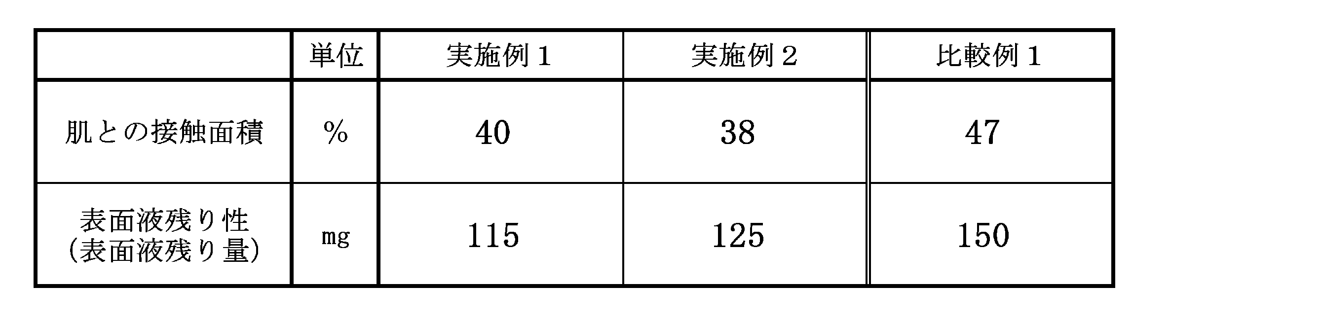
表1の結果によれば、実施例1,2の繊維シートは、比較例1の繊維シートに比べて肌との接触面積が低くなっている。従って、実施例1,2の繊維シートを、例えば吸収性物品の表面シートに用いると、べたつき感やムレをさらに低減し、肌へのダメージを減らす効果が期待できる。また、実施例1,2の繊維シートは、比較例1の繊維シートに比べて表面液残り量が低くなっている。従って、実施例1,2の繊維シートを、例えば吸収性物品の表面シートに用いると、表面液戻り性が低いので、べたつき感やムレをさらに低減し、肌へのダメージを減らすことができる。
本発明の繊維シートによれば、例えば吸収性物品用の表面シートに用いると、着用者の肌との接触面積をさらに低減すると共に、べたつき感やムレをさらに低減し、肌へのダメージを減らすことができる。
Claims (9)
- 熱収縮した熱収縮性繊維を含む熱収縮繊維層を有し、複数のエンボス部が形成された繊維シートであって、
最も高さの高い半球状の高凸部と、最も高さの低い半球状の低凸部と、更に該高凸部より高さが低く且つ該低凸部より高さの高い半球状の中凸部とを、それぞれ複数有し、
前記中凸部は、第1方向に間隔を空けて複数配されており、該中凸部を該第1方向に複数配して形成された第1の凸部列が、該第1方向に直交する第2方向に間隔を空けて複数配されており、
前記高凸部は、前記第1方向に間隔を空けて複数配されており、該高凸部を該第1方向に複数配して形成された第2の凸部列が、前記第2方向に、前記第1の凸部列と交互に配されて、各該高凸部が4個の前記中凸部で囲まれており、
複数の前記低凸部は、それぞれ、前記第1方向に隣り合う前記中凸部どうしの間で且つ前記第2方向に隣り合う前記高凸部どうしの間毎に配されている繊維シート。 - 前記複数のエンボス部それぞれは、平面視して、中心点から3本の棒状体が延出した形状であり、
各前記中凸部は、2個の前記エンボス部に囲まれており、
各前記高凸部は、4個の前記エンボス部に囲まれており、
各前記低凸部は、4個の前記エンボス部それぞれにおける前記棒状体の先端どうしが向かい合う位置に配されている請求項1に記載の繊維シート。 - 前記エンボス部の3本の前記棒状体は、2本の長い長棒状体と1本の短い短棒状体とからなり、
各前記中凸部は、2個の前記エンボス部それぞれにおける2本の前記長棒状体に囲まれており、
各前記高凸部は、4個の前記エンボス部それぞれにおける1本の前記長棒状体と1本の前記短棒状体とに囲まれており、
各前記低凸部は、4個の前記エンボス部それぞれにおける前記長棒状体の先端どうしが向かい合う位置に配されている請求項2に記載の繊維シート。 - 前記第2方向に隣り合う前記中凸部どうしは、前記第1方向に平行に延びる仮想二等分線に対して対称に配された一対の前記エンボス部を介して配されており、
前記第1方向に隣り合う前記高凸部どうしは、一対の前記エンボス部を介して配されている請求項2又は3に記載の繊維シート。 - 前記エンボス部の密度は1個/cm2以上32個/cm2以下であり、前記第1方向に隣り合う前記エンボス部どうしの間隔は0.5mm以上5mm以下である請求項2~4の何れか1項に記載の繊維シート。
- 前記熱収縮繊維層に積層された非熱収縮性繊維からなる非熱収縮繊維層を有し、該熱収縮繊維層と該非熱収縮繊維層とが、前記複数のエンボス部により、間欠的に接合されている請求項1~5の何れか1項に記載の繊維シート。
- 請求項1~6の何れか1項に記載の繊維シートからなる、吸収性物品の表面シート。
- 前記非熱収縮繊維層を肌当接面側に配し、前記熱収縮繊維層を非肌当接面側に配した請求項7に記載の吸収性物品の表面シート。
- 請求項7又は8に記載の表面シートを備える吸収性物品。
Priority Applications (1)
| Application Number | Priority Date | Filing Date | Title |
|---|---|---|---|
| CN201380045520.8A CN104603346B (zh) | 2012-09-28 | 2013-08-02 | 纤维片 |
Applications Claiming Priority (2)
| Application Number | Priority Date | Filing Date | Title |
|---|---|---|---|
| JP2012216012A JP5875157B2 (ja) | 2012-09-28 | 2012-09-28 | 繊維シート |
| JP2012-216012 | 2012-09-28 |
Publications (1)
| Publication Number | Publication Date |
|---|---|
| WO2014050310A1 true WO2014050310A1 (ja) | 2014-04-03 |
Family
ID=50387724
Family Applications (1)
| Application Number | Title | Priority Date | Filing Date |
|---|---|---|---|
| PCT/JP2013/071044 Ceased WO2014050310A1 (ja) | 2012-09-28 | 2013-08-02 | 繊維シート |
Country Status (3)
| Country | Link |
|---|---|
| JP (1) | JP5875157B2 (ja) |
| TW (1) | TWI572338B (ja) |
| WO (1) | WO2014050310A1 (ja) |
Cited By (9)
| Publication number | Priority date | Publication date | Assignee | Title |
|---|---|---|---|---|
| WO2016098796A1 (ja) * | 2014-12-17 | 2016-06-23 | 花王株式会社 | 液膜開裂剤 |
| JP2016220732A (ja) * | 2015-05-27 | 2016-12-28 | 日本製紙クレシア株式会社 | 吸収性物品 |
| KR20170086507A (ko) * | 2014-11-19 | 2017-07-26 | 다이오 페이퍼 코퍼레이션 | 흡수성 물품의 제조 방법 및 흡수성 물품 |
| CN108601691A (zh) * | 2016-02-10 | 2018-09-28 | 大王制纸株式会社 | 垫型一次性尿布 |
| EP3424476A4 (en) * | 2016-02-29 | 2019-03-20 | Daio Paper Corporation | DISPOSABLE DIAPERS |
| JP2019063229A (ja) * | 2017-09-29 | 2019-04-25 | 大王製紙株式会社 | 生理用ナプキン |
| US20190262196A1 (en) * | 2018-02-23 | 2019-08-29 | The Procter & Gamble Company | Substrates and Laminates for Absorbent Articles |
| US20200100956A1 (en) * | 2018-09-27 | 2020-04-02 | The Procter & Gamble Company | Nonwoven webs with visually discernible patterns |
| US10912682B2 (en) | 2015-09-25 | 2021-02-09 | Daio Paper Corporation | Absorbent article |
Families Citing this family (15)
| Publication number | Priority date | Publication date | Assignee | Title |
|---|---|---|---|---|
| BR112017003964A2 (ja) * | 2014-09-02 | 2018-06-26 | Oji Holdings Corporation | The top sheet of an absorptive article |
| JP6436708B2 (ja) * | 2014-09-29 | 2018-12-12 | 大王製紙株式会社 | 吸収性物品 |
| JP6083909B2 (ja) * | 2014-12-19 | 2017-02-22 | 花王株式会社 | 吸収性物品 |
| JP6393611B2 (ja) * | 2014-12-19 | 2018-09-19 | 花王株式会社 | 複合シート及びそれを備えた吸収性物品 |
| JP6437877B2 (ja) * | 2015-04-30 | 2018-12-12 | 日本製紙クレシア株式会社 | 吸収性物品 |
| CN109348722B (zh) | 2015-07-31 | 2022-04-08 | 宝洁公司 | 用于成型非织造布的成形带 |
| CA2992031C (en) | 2015-07-31 | 2021-02-16 | The Procter & Gamble Company | Package of absorbent articles utilizing a shaped nonwoven |
| CA3195107A1 (en) * | 2015-12-17 | 2017-06-22 | The Procter & Gamble Company | Shaped nonwoven |
| JP6744121B2 (ja) * | 2016-04-14 | 2020-08-19 | 花王株式会社 | 不織布 |
| PL3239378T3 (pl) | 2016-04-29 | 2019-07-31 | Reifenhäuser GmbH & Co. KG Maschinenfabrik | Urządzenie i sposób do wytwarzania włóknin z włókien ciągłych |
| JP6271657B1 (ja) * | 2016-08-09 | 2018-01-31 | 花王株式会社 | 吸収性物品用の表面シート |
| GB2596718A (en) * | 2019-03-18 | 2022-01-05 | Procter & Gamble | Shaped nonwovens that exhibit high visual resolution |
| EP4725467A2 (en) | 2019-12-10 | 2026-04-15 | The Procter & Gamble Company | Nonwoven webs with visually discernible patterns and improved texture perception |
| JP7776962B2 (ja) * | 2021-10-05 | 2025-11-27 | 花王株式会社 | 吸収性物品用の表面シート |
| WO2023188404A1 (ja) * | 2022-03-31 | 2023-10-05 | ユニ・チャーム株式会社 | 不織布、及び当該不織布の製造方法 |
Citations (4)
| Publication number | Priority date | Publication date | Assignee | Title |
|---|---|---|---|---|
| JPH04327255A (ja) * | 1991-04-26 | 1992-11-16 | Nippon Filcon Co Ltd | 突起を設けた不織布製造用ベルト及び模様を形成した不織布の製造方法 |
| JP2001020168A (ja) * | 1999-07-05 | 2001-01-23 | Kao Corp | 圧縮回復性シート及びその製造方法並びにそれを用いた吸収性物品 |
| JP2004113489A (ja) * | 2002-09-26 | 2004-04-15 | Asahi Kasei Fibers Corp | 柔軟な衛生材料用不織布及び使い捨て衛生材料 |
| JP2009201964A (ja) * | 2007-12-28 | 2009-09-10 | Kao Corp | 賦形シート及びこれを用いた吸収性物品 |
Family Cites Families (4)
| Publication number | Priority date | Publication date | Assignee | Title |
|---|---|---|---|---|
| AU2003266572A1 (en) * | 2002-09-26 | 2004-04-19 | Asahi Kasei Fibers Corporation | Spun-bonded nonwoven fabric and sanitary supplies |
| EP2189562B1 (en) * | 2007-08-28 | 2014-11-12 | Kao Corporation | Shaped sheet and absorbent article using the same |
| TW200951264A (en) * | 2008-06-06 | 2009-12-16 | Kang Na Hsiung Entpr Co Ltd | Nonwoven embossing device and nonwoven with two-sided repousse |
| JP5268662B2 (ja) * | 2009-01-09 | 2013-08-21 | 花王株式会社 | 吸収性物品の表面シート |
-
2012
- 2012-09-28 JP JP2012216012A patent/JP5875157B2/ja not_active Expired - Fee Related
-
2013
- 2013-08-02 WO PCT/JP2013/071044 patent/WO2014050310A1/ja not_active Ceased
- 2013-08-13 TW TW102129029A patent/TWI572338B/zh not_active IP Right Cessation
Patent Citations (4)
| Publication number | Priority date | Publication date | Assignee | Title |
|---|---|---|---|---|
| JPH04327255A (ja) * | 1991-04-26 | 1992-11-16 | Nippon Filcon Co Ltd | 突起を設けた不織布製造用ベルト及び模様を形成した不織布の製造方法 |
| JP2001020168A (ja) * | 1999-07-05 | 2001-01-23 | Kao Corp | 圧縮回復性シート及びその製造方法並びにそれを用いた吸収性物品 |
| JP2004113489A (ja) * | 2002-09-26 | 2004-04-15 | Asahi Kasei Fibers Corp | 柔軟な衛生材料用不織布及び使い捨て衛生材料 |
| JP2009201964A (ja) * | 2007-12-28 | 2009-09-10 | Kao Corp | 賦形シート及びこれを用いた吸収性物品 |
Cited By (25)
| Publication number | Priority date | Publication date | Assignee | Title |
|---|---|---|---|---|
| KR20170086507A (ko) * | 2014-11-19 | 2017-07-26 | 다이오 페이퍼 코퍼레이션 | 흡수성 물품의 제조 방법 및 흡수성 물품 |
| KR102454298B1 (ko) | 2014-11-19 | 2022-10-14 | 다이오 페이퍼 코퍼레이션 | 흡수성 물품의 제조 방법 및 흡수성 물품 |
| US11141324B2 (en) | 2014-11-19 | 2021-10-12 | Daio Paper Corporation | Method for manufacturing absorbent article and absorbent sanitary article |
| EP3222257A4 (en) * | 2014-11-19 | 2018-07-11 | Daio Paper Corporation | Method for manufacturing absorbent article and absorbent article |
| RU2703625C2 (ru) * | 2014-12-17 | 2019-10-21 | Као Корпорейшн | Разрушающий жидкостную пленку агент |
| EP3235945A4 (en) * | 2014-12-17 | 2018-08-29 | Kao Corporation | Liquid film cleavage agent |
| JP2016117981A (ja) * | 2014-12-17 | 2016-06-30 | 花王株式会社 | 液膜開裂剤 |
| WO2016098796A1 (ja) * | 2014-12-17 | 2016-06-23 | 花王株式会社 | 液膜開裂剤 |
| JP6051333B1 (ja) * | 2014-12-17 | 2016-12-27 | 花王株式会社 | 液膜開裂剤 |
| CN111364241A (zh) * | 2014-12-17 | 2020-07-03 | 花王株式会社 | 液膜开裂剂 |
| JP2016220732A (ja) * | 2015-05-27 | 2016-12-28 | 日本製紙クレシア株式会社 | 吸収性物品 |
| US10912682B2 (en) | 2015-09-25 | 2021-02-09 | Daio Paper Corporation | Absorbent article |
| US10987258B2 (en) | 2016-02-10 | 2021-04-27 | Daio Paper Corporation | Pad type disposable diaper |
| CN108601691A (zh) * | 2016-02-10 | 2018-09-28 | 大王制纸株式会社 | 垫型一次性尿布 |
| EP3415132A4 (en) * | 2016-02-10 | 2019-03-20 | Daio Paper Corporation | DISPOSABLE WINDLE FROM PADTYP |
| EP3424476A4 (en) * | 2016-02-29 | 2019-03-20 | Daio Paper Corporation | DISPOSABLE DIAPERS |
| US11013643B2 (en) | 2016-02-29 | 2021-05-25 | Daio Paper Corporation | Disposable diaper |
| JP7049794B2 (ja) | 2017-09-29 | 2022-04-07 | 大王製紙株式会社 | 生理用ナプキン |
| JP2019063229A (ja) * | 2017-09-29 | 2019-04-25 | 大王製紙株式会社 | 生理用ナプキン |
| US10792199B2 (en) * | 2018-02-23 | 2020-10-06 | The Procter & Gamble Company | Substrates and laminates for absorbent articles |
| US20190262196A1 (en) * | 2018-02-23 | 2019-08-29 | The Procter & Gamble Company | Substrates and Laminates for Absorbent Articles |
| US11864984B2 (en) | 2018-02-23 | 2024-01-09 | The Procter And Gamble Company | Substrates and laminates for absorbent articles |
| US12558272B2 (en) | 2018-02-23 | 2026-02-24 | The Procter & Gamble Company | Substrates and laminates for absorbent articles |
| US20200100956A1 (en) * | 2018-09-27 | 2020-04-02 | The Procter & Gamble Company | Nonwoven webs with visually discernible patterns |
| US11998427B2 (en) * | 2018-09-27 | 2024-06-04 | The Procter & Gamble Company | Nonwoven webs with visually discernible patterns |
Also Published As
| Publication number | Publication date |
|---|---|
| CN104603346A (zh) | 2015-05-06 |
| JP2014070299A (ja) | 2014-04-21 |
| TWI572338B (zh) | 2017-03-01 |
| JP5875157B2 (ja) | 2016-03-02 |
| TW201417784A (zh) | 2014-05-16 |
Similar Documents
| Publication | Publication Date | Title |
|---|---|---|
| JP5875157B2 (ja) | 繊維シート | |
| JP6310294B2 (ja) | 吸収性物品用の表面シート | |
| JP4343992B2 (ja) | 吸収性物品の表面シート | |
| JP6006068B2 (ja) | 繊維シート | |
| JP5421676B2 (ja) | 吸収性物品用の表面シート | |
| JP6273101B2 (ja) | 不織布 | |
| JP5507193B2 (ja) | 吸収性物品の表面シート | |
| JP3877682B2 (ja) | 吸収性物品用の表面シート | |
| CN104246046B (zh) | 无纺布、吸收性物品、卫生巾以及无纺布的制造方法 | |
| JP2003126147A (ja) | 吸収性物品用の表面シート | |
| CN108366891A (zh) | 吸收性物品用的正面片 | |
| JP2012090689A (ja) | 吸収性物品 | |
| JP6172808B2 (ja) | 吸収性物品の表面シート | |
| JP2005015964A (ja) | シート材料 | |
| JP2017086621A (ja) | 吸収性物品 | |
| CN1986210B (zh) | 无纺布 | |
| JP6632343B2 (ja) | 吸収性物品 | |
| CN109496242B (zh) | 吸收性物品的透液性片用的层叠无纺布及上述层叠无纺布在吸收性物品的透液性片中的使用 | |
| TWI238711B (en) | Topsheet of absorbent article and absorbent article having the same | |
| JP3926250B2 (ja) | 吸収性物品 | |
| JP2017094048A (ja) | 吸収性物品 | |
| JP6492204B2 (ja) | 吸収性物品用の表面シート | |
| KR101459016B1 (ko) | 흡수성 물품의 표면 시트 | |
| JP2021078918A (ja) | 吸収性物品用シート及びこれを用いた吸収性物品 | |
| CN104603346B (zh) | 纤维片 |
Legal Events
| Date | Code | Title | Description |
|---|---|---|---|
| 121 | Ep: the epo has been informed by wipo that ep was designated in this application |
Ref document number: 13842726 Country of ref document: EP Kind code of ref document: A1 |
|
| NENP | Non-entry into the national phase |
Ref country code: DE |
|
| 122 | Ep: pct application non-entry in european phase |
Ref document number: 13842726 Country of ref document: EP Kind code of ref document: A1 |