WO2014041966A1 - インサート成形用金型、射出成形方法、及びその金型によって形成された樹脂成形品 - Google Patents
インサート成形用金型、射出成形方法、及びその金型によって形成された樹脂成形品 Download PDFInfo
- Publication number
- WO2014041966A1 WO2014041966A1 PCT/JP2013/072176 JP2013072176W WO2014041966A1 WO 2014041966 A1 WO2014041966 A1 WO 2014041966A1 JP 2013072176 W JP2013072176 W JP 2013072176W WO 2014041966 A1 WO2014041966 A1 WO 2014041966A1
- Authority
- WO
- WIPO (PCT)
- Prior art keywords
- resin
- space
- mold
- insert molding
- wire cable
- Prior art date
- Legal status (The legal status is an assumption and is not a legal conclusion. Google has not performed a legal analysis and makes no representation as to the accuracy of the status listed.)
- Ceased
Links
Images



Classifications
-
- B—PERFORMING OPERATIONS; TRANSPORTING
- B29—WORKING OF PLASTICS; WORKING OF SUBSTANCES IN A PLASTIC STATE IN GENERAL
- B29C—SHAPING OR JOINING OF PLASTICS; SHAPING OF MATERIAL IN A PLASTIC STATE, NOT OTHERWISE PROVIDED FOR; AFTER-TREATMENT OF THE SHAPED PRODUCTS, e.g. REPAIRING
- B29C45/00—Injection moulding, i.e. forcing the required volume of moulding material through a nozzle into a closed mould; Apparatus therefor
- B29C45/14—Injection moulding, i.e. forcing the required volume of moulding material through a nozzle into a closed mould; Apparatus therefor incorporating preformed parts or layers, e.g. injection moulding around inserts or for coating articles
- B29C45/14549—Coating rod-like, wire-like or belt-like articles
-
- B—PERFORMING OPERATIONS; TRANSPORTING
- B29—WORKING OF PLASTICS; WORKING OF SUBSTANCES IN A PLASTIC STATE IN GENERAL
- B29C—SHAPING OR JOINING OF PLASTICS; SHAPING OF MATERIAL IN A PLASTIC STATE, NOT OTHERWISE PROVIDED FOR; AFTER-TREATMENT OF THE SHAPED PRODUCTS, e.g. REPAIRING
- B29C45/00—Injection moulding, i.e. forcing the required volume of moulding material through a nozzle into a closed mould; Apparatus therefor
- B29C45/14—Injection moulding, i.e. forcing the required volume of moulding material through a nozzle into a closed mould; Apparatus therefor incorporating preformed parts or layers, e.g. injection moulding around inserts or for coating articles
- B29C45/14467—Joining articles or parts of a single article
-
- B—PERFORMING OPERATIONS; TRANSPORTING
- B29—WORKING OF PLASTICS; WORKING OF SUBSTANCES IN A PLASTIC STATE IN GENERAL
- B29C—SHAPING OR JOINING OF PLASTICS; SHAPING OF MATERIAL IN A PLASTIC STATE, NOT OTHERWISE PROVIDED FOR; AFTER-TREATMENT OF THE SHAPED PRODUCTS, e.g. REPAIRING
- B29C45/00—Injection moulding, i.e. forcing the required volume of moulding material through a nozzle into a closed mould; Apparatus therefor
- B29C45/14—Injection moulding, i.e. forcing the required volume of moulding material through a nozzle into a closed mould; Apparatus therefor incorporating preformed parts or layers, e.g. injection moulding around inserts or for coating articles
- B29C45/14639—Injection moulding, i.e. forcing the required volume of moulding material through a nozzle into a closed mould; Apparatus therefor incorporating preformed parts or layers, e.g. injection moulding around inserts or for coating articles for obtaining an insulating effect, e.g. for electrical components
-
- B—PERFORMING OPERATIONS; TRANSPORTING
- B29—WORKING OF PLASTICS; WORKING OF SUBSTANCES IN A PLASTIC STATE IN GENERAL
- B29C—SHAPING OR JOINING OF PLASTICS; SHAPING OF MATERIAL IN A PLASTIC STATE, NOT OTHERWISE PROVIDED FOR; AFTER-TREATMENT OF THE SHAPED PRODUCTS, e.g. REPAIRING
- B29C45/00—Injection moulding, i.e. forcing the required volume of moulding material through a nozzle into a closed mould; Apparatus therefor
- B29C45/17—Component parts, details or accessories; Auxiliary operations
- B29C45/72—Heating or cooling
- B29C45/73—Heating or cooling of the mould
-
- B—PERFORMING OPERATIONS; TRANSPORTING
- B29—WORKING OF PLASTICS; WORKING OF SUBSTANCES IN A PLASTIC STATE IN GENERAL
- B29C—SHAPING OR JOINING OF PLASTICS; SHAPING OF MATERIAL IN A PLASTIC STATE, NOT OTHERWISE PROVIDED FOR; AFTER-TREATMENT OF THE SHAPED PRODUCTS, e.g. REPAIRING
- B29C45/00—Injection moulding, i.e. forcing the required volume of moulding material through a nozzle into a closed mould; Apparatus therefor
- B29C45/17—Component parts, details or accessories; Auxiliary operations
- B29C45/76—Measuring, controlling or regulating
- B29C45/7646—Measuring, controlling or regulating viscosity
-
- B—PERFORMING OPERATIONS; TRANSPORTING
- B29—WORKING OF PLASTICS; WORKING OF SUBSTANCES IN A PLASTIC STATE IN GENERAL
- B29C—SHAPING OR JOINING OF PLASTICS; SHAPING OF MATERIAL IN A PLASTIC STATE, NOT OTHERWISE PROVIDED FOR; AFTER-TREATMENT OF THE SHAPED PRODUCTS, e.g. REPAIRING
- B29C45/00—Injection moulding, i.e. forcing the required volume of moulding material through a nozzle into a closed mould; Apparatus therefor
- B29C45/14—Injection moulding, i.e. forcing the required volume of moulding material through a nozzle into a closed mould; Apparatus therefor incorporating preformed parts or layers, e.g. injection moulding around inserts or for coating articles
- B29C2045/1486—Details, accessories and auxiliary operations
- B29C2045/14934—Preventing penetration of injected material between insert and adjacent mould wall
-
- B—PERFORMING OPERATIONS; TRANSPORTING
- B29—WORKING OF PLASTICS; WORKING OF SUBSTANCES IN A PLASTIC STATE IN GENERAL
- B29C—SHAPING OR JOINING OF PLASTICS; SHAPING OF MATERIAL IN A PLASTIC STATE, NOT OTHERWISE PROVIDED FOR; AFTER-TREATMENT OF THE SHAPED PRODUCTS, e.g. REPAIRING
- B29C2945/00—Indexing scheme relating to injection moulding, i.e. forcing the required volume of moulding material through a nozzle into a closed mould
- B29C2945/76—Measuring, controlling or regulating
- B29C2945/76003—Measured parameter
- B29C2945/7604—Temperature
-
- B—PERFORMING OPERATIONS; TRANSPORTING
- B29—WORKING OF PLASTICS; WORKING OF SUBSTANCES IN A PLASTIC STATE IN GENERAL
- B29C—SHAPING OR JOINING OF PLASTICS; SHAPING OF MATERIAL IN A PLASTIC STATE, NOT OTHERWISE PROVIDED FOR; AFTER-TREATMENT OF THE SHAPED PRODUCTS, e.g. REPAIRING
- B29C2945/00—Indexing scheme relating to injection moulding, i.e. forcing the required volume of moulding material through a nozzle into a closed mould
- B29C2945/76—Measuring, controlling or regulating
- B29C2945/76177—Location of measurement
- B29C2945/76254—Mould
- B29C2945/76257—Mould cavity
- B29C2945/7626—Mould cavity cavity walls
-
- B—PERFORMING OPERATIONS; TRANSPORTING
- B29—WORKING OF PLASTICS; WORKING OF SUBSTANCES IN A PLASTIC STATE IN GENERAL
- B29C—SHAPING OR JOINING OF PLASTICS; SHAPING OF MATERIAL IN A PLASTIC STATE, NOT OTHERWISE PROVIDED FOR; AFTER-TREATMENT OF THE SHAPED PRODUCTS, e.g. REPAIRING
- B29C2945/00—Indexing scheme relating to injection moulding, i.e. forcing the required volume of moulding material through a nozzle into a closed mould
- B29C2945/76—Measuring, controlling or regulating
- B29C2945/76344—Phase or stage of measurement
- B29C2945/76381—Injection
-
- B—PERFORMING OPERATIONS; TRANSPORTING
- B29—WORKING OF PLASTICS; WORKING OF SUBSTANCES IN A PLASTIC STATE IN GENERAL
- B29C—SHAPING OR JOINING OF PLASTICS; SHAPING OF MATERIAL IN A PLASTIC STATE, NOT OTHERWISE PROVIDED FOR; AFTER-TREATMENT OF THE SHAPED PRODUCTS, e.g. REPAIRING
- B29C2945/00—Indexing scheme relating to injection moulding, i.e. forcing the required volume of moulding material through a nozzle into a closed mould
- B29C2945/76—Measuring, controlling or regulating
- B29C2945/76494—Controlled parameter
- B29C2945/76538—Viscosity
-
- B—PERFORMING OPERATIONS; TRANSPORTING
- B29—WORKING OF PLASTICS; WORKING OF SUBSTANCES IN A PLASTIC STATE IN GENERAL
- B29C—SHAPING OR JOINING OF PLASTICS; SHAPING OF MATERIAL IN A PLASTIC STATE, NOT OTHERWISE PROVIDED FOR; AFTER-TREATMENT OF THE SHAPED PRODUCTS, e.g. REPAIRING
- B29C2945/00—Indexing scheme relating to injection moulding, i.e. forcing the required volume of moulding material through a nozzle into a closed mould
- B29C2945/76—Measuring, controlling or regulating
- B29C2945/76822—Phase or stage of control
- B29C2945/76859—Injection
-
- B—PERFORMING OPERATIONS; TRANSPORTING
- B29—WORKING OF PLASTICS; WORKING OF SUBSTANCES IN A PLASTIC STATE IN GENERAL
- B29C—SHAPING OR JOINING OF PLASTICS; SHAPING OF MATERIAL IN A PLASTIC STATE, NOT OTHERWISE PROVIDED FOR; AFTER-TREATMENT OF THE SHAPED PRODUCTS, e.g. REPAIRING
- B29C2945/00—Indexing scheme relating to injection moulding, i.e. forcing the required volume of moulding material through a nozzle into a closed mould
- B29C2945/76—Measuring, controlling or regulating
- B29C2945/76929—Controlling method
- B29C2945/76933—The operating conditions are corrected immediately, during the same phase or cycle
-
- B—PERFORMING OPERATIONS; TRANSPORTING
- B29—WORKING OF PLASTICS; WORKING OF SUBSTANCES IN A PLASTIC STATE IN GENERAL
- B29C—SHAPING OR JOINING OF PLASTICS; SHAPING OF MATERIAL IN A PLASTIC STATE, NOT OTHERWISE PROVIDED FOR; AFTER-TREATMENT OF THE SHAPED PRODUCTS, e.g. REPAIRING
- B29C2945/00—Indexing scheme relating to injection moulding, i.e. forcing the required volume of moulding material through a nozzle into a closed mould
- B29C2945/76—Measuring, controlling or regulating
- B29C2945/76929—Controlling method
- B29C2945/76939—Using stored or historical data sets
- B29C2945/76946—Using stored or historical data sets using an expert system, i.e. the system possesses a database in which human experience is stored, e.g. to help interfering the possible cause of a fault
Definitions
- the present invention relates to an insert mold used for a resin mold of a wire cable, an injection molding method using the mold, and a resin molded product formed using the mold.
- a protective component such as a heat-shrinkable tube or heat-resistant tape is used before injection molding as in the method described in Patent Document 1. It is conceivable to protect the wire cable.
- Patent Document 1 when the method of Patent Document 1 is used, a process for protecting the wire cable with a protective component is required, which complicates the manufacturing process. And the manufacturing cost becomes high by the increase in the number of parts. In addition, when pressure is indirectly applied to the wire cable from the mold via the protective component, the covering portion of the wire cable may be damaged.
- the present invention has been made in view of the above problems, and provides an insert molding die, an injection molding method, and a resin molded product formed by the die, which can reduce the burden on a wire cable. With the goal.
- the mold for insert molding fills the periphery of the covering portion with the first space in which the resin and the covering portion of the wire cable are filled with the resin, and the cross-sectional area is smaller than that of the first space.
- a second space and a support portion that supports the covering portion are provided.
- the support portion supports the covering portion so that the covering portion of the wire cable is located in the center of the second space, it is possible to provide resin all around the covering portion. Therefore, by using this insert molding die, it is possible to prevent peeling of the resin provided around the covering portion.
- the protective component for protecting the wire cable is not used as in the method described in Patent Document 1, the manufacturing process can be simplified and the manufacturing cost can be reduced.
- die part which has 2nd space, and a support part may be comprised integrally, or may be comprised separately.
- the second space is adjusted by adjusting the pressure of the molten resin supplied from the gate to the first space, the resin viscosity, or the curing time of the molten resin.
- the length or thickness of the resin filled in is set. This makes it possible to control the length or thickness of the resin provided around the covering portion of the wire cable.
- the present invention can also be understood as a resin molded product formed by the above injection molding method.
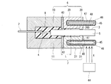
- die for insert molding by 1st Embodiment of this invention Explanatory drawing of the injection molding method using the metal mold
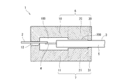
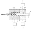
- FIGS. 1 to 3 show a mold for insert molding according to a first embodiment of the present invention
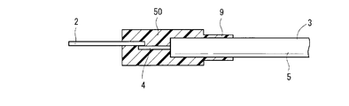
- FIG. 4 shows a resin molded product molded thereby.
- the insert molding die 1 according to the present embodiment is used for insert molding of a connecting portion between a lead wire 2 of an electronic component and a conductor 4 of a wire cable 3 and a covering portion 5 of the wire cable 3 with a thermosetting resin. It is done.
- the main body of the electronic component is omitted. *
- the insert molding die 1 includes an upper die 6 and a lower die 7.
- the upper mold 6 includes a first upper mold part 10, a second upper mold part 20, and an upper support part 30, and the lower mold 7 includes a first lower mold part 11, a second lower mold part 21, and
- the lower support part 31 is comprised.
- first upper mold part 10 and the first lower mold part 11 are simply referred to as first mold parts 10 and 11
- second upper mold part 20 and the second lower mold part 21 are simply referred to as second molds.
- the mold parts 20 and 21 are referred to, and the upper support part 30 and the lower support part 31 are simply referred to as support parts 30 and 31.
- the boundary between the first mold part 10, 11 and the second mold part 20, 21 and the boundary between the second mold part 20, 21 and the support part 30, 31 are conceptually shown. Although shown with a dashed-dotted line, the 1st metal mold
- the first mold parts 10 and 11 have a first space 100.
- the first space 100 can accommodate the lead wire 2 and the wire cable 3 of the electronic component to be inserted, and can fill resin around them.
- the first mold parts 10 and 11 are provided with a gate 13 for filling the first space 100 with molten resin at the time of injection molding.
- the second mold parts 20 and 21 have a second space 200.
- the second space 200 has a smaller cross-sectional area than the first space 100 and communicates with the first space 100.
- the second space 200 can accommodate the covering portion 5 of the wire cable 3 to be inserted, and can fill the periphery of the covering portion 5 with resin.
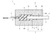
- the second space 200 is set to have a cross-sectional area and a length that allow the molten resin to stop flowing in the middle of the second space 200 at the time of injection molding based on the following formula 1. *
- L is the length (mm) of the resin with which the second space 200 is filled.
- the resin filled in the second space 200 is referred to as “overflow portion”, and the length of the resin is referred to as “overflow length”.
- H is the thickness (mm) of the overflow portion.
- P is the pressure (Pa) of the molten resin in the first space 100.
- ⁇ is the viscosity (Pa ⁇ s) of the molten resin flowing in the second space 200.
- t is a time (s) from when the molten resin filled in the first space 100 starts to flow into the second space 200 until the molten resin is cured in the second space 200.
- the thickness h of the overflow portion is 0.01 mm
- the pressure P of the molten resin in the first space 100 is 5000 Pa
- the viscosity ⁇ of the molten resin flowing through the second space 200 is 10 Pa ⁇ s
- the first space 100 is filled.
- the overflow length L is 3.5 mm.
- die parts 20 and 21 set the clearance gap between the inner wall of the 2nd space 200, and the coating
- the support portions 30 and 31 are provided on the opposite side of the second space 200 from the first space 100.
- the support portions 30 and 31 support the covering portion 5 so that the wire cable 3 is positioned at the center of the second space 200 without pressing the wire cable 3. Thereby, in the second space 200, the space 200 is formed on the entire circumference of the covering portion 5 of the wire cable 3.
- the upper mold 6 and the lower mold 7 are opened, and the lead wire 2 and the wire cable 3 of the electronic component are installed between them.
- a connection portion between the lead wire 2 and the conductor 4 of the wire cable 3 and a portion where the conductor 4 protrudes from the covering portion 5 of the wire cable 3 are located in the first space 100.
- the lead wire 2 of the electronic component and the conductor 4 of the wire cable 3 are connected by soldering or welding.
- die parts 10 and 11 are good also as a structure which accommodates the main body of an electronic component in the 1st space 100 with the lead wire 2 of an electronic component.
- the covering portion 5 of the wire cable 3 is located in the first space 100 and the second space 200.
- the upper mold 6 and the lower mold 7 are closed, and the resin 8 heated and melted by an injection unit (not shown) is transferred from the gate 13 of the first mold parts 10 and 11 to the first space 100.
- the molten resin 8 is a thermosetting resin, specifically an epoxy resin.
- the upper mold 6 and the lower mold 7 are heated to a predetermined temperature (for example, 170 ° C.) suitable for injection molding of the thermosetting resin used by a heating device (not shown). *
- the molten resin 8 filled in the first space 100 flows into the second space 200.
- the molten resin 8 that has flowed into the second space 200 stops flowing in the second space 200 due to flow resistance in the second space 200.
- the pressure P of the molten resin 8 supplied from the gate 13 to the first space 100, the resin viscosity ⁇ , and the curing time t of the molten resin 8 are adjusted.
- the length of the resin filled in the second space 200 that is, the overflow length L is set.
- the upper and lower molds 6 and 7 maintain the pressure of the molten resin therein while the predetermined temperature is maintained until the resin curing time t elapses. After the curing time t has elapsed, the upper mold 6 and the lower mold 7 are opened. *
- the insert molding die 1 includes a first space 100, a second space 200, and support portions 30 and 31.
- the cross-sectional area and length of the second space 200 so that the molten resin 8 stops flowing in the middle of the second space 200 due to the flow resistance in the second space 200 at the time of injection molding, Generation
- flash can be suppressed, without resin leaking from the clearance gap between 31 and the wire cable 3.
- the support portions 30 and 31 support the covering portion 5 so that the covering portion 5 of the wire cable 3 is located in the center of the second space 200. Therefore, since the overflow part 9 is provided in the perimeter of the coating
- the pressure P, the resin viscosity ⁇ , or the curing time t of the molten resin 8 supplied from the gate 13 to the first space 100 is adjusted. Thereby, the wall thickness h or the overflow length L of the overflow part 9 can be controlled.
- the resin used for injection molding is a thermosetting resin.
- the insert molding mold 1 has a burden on the wire cable 3 due to the heat of the mold and a burden on the wire cable 3 due to the pressing force of the mold. It is suitable for reducing.
- thermosetting resin is an epoxy resin.
- the high adhesiveness of the epoxy resin can prevent the overflow portion 9 from peeling off from the covering portion 5.
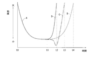
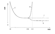
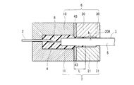
- FIGS. 5 to 8 show an insert molding die according to a second embodiment of the present invention. Moreover, the graph which shows the relationship between the heating time by a thermosetting resin and resin viscosity is shown in FIG. 9, and the graph which shows the relationship between the heating time by a thermoplastic resin and resin viscosity is shown in FIG.
- the same reference numerals are given to substantially the same components as those in the first embodiment described above, and the description thereof is omitted.
- the boundary between the second mold part 20, 21 and the support part 30, 31 is conceptually indicated by a one-dot chain line, but these may be integrally formed. Alternatively, it may be configured separately. *
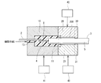
- the second mold parts 20 and 21 are made of a material having a higher thermal conductivity than the first mold parts 10 and 11.
- the material having high thermal conductivity include copper and aluminum.
- the cooling means which can cool the 2nd metal mold
- the cooling means is, for example, a cooling device 40 that causes a cooling liquid to flow through a liquid flow path (not shown) provided in the second mold parts 20 and 21.
- the cooling means includes, for example, the first heating device 41 that heats the first mold parts 10 and 11 and the second heating device 42 that heats the second mold parts 20 and 21. It can also be realized by reducing only the heating temperature.
- the molten resin 8 filled in the first space 100 flows into the second space 200.
- the second mold parts 20, 21 have higher heat dissipation than the first mold parts 10, 11, the operation of the cooling device 40, or the temperature setting of the second heating device 42, so The temperature is set lower than that of the mold parts 10 and 11. Therefore, the viscosity ⁇ of the molten resin 8 flowing through the second space 200 increases at the position indicated by the alternate long and short dash line ⁇ in FIG. Thereby, as shown in FIG. 8, the molten resin 8 flowing in the second space 200 stops at a predetermined overflow length L due to the flow resistance in the second space 200.
- the upper and lower molds 6 and 7 maintain the pressure of the molten resin therein while the predetermined temperature is maintained until the resin curing time t elapses. After the curing time t has elapsed, the upper mold 6 and the lower mold 7 are opened, and the resin molded product is taken out.
- thermosetting resin is heated at a constant temperature (for example, 170 ° C.) from time t0 to time t1. Then, after time t1, the case where the resin is continuously heated at the same temperature is indicated by a broken line B, after time t1, the case where the resin is rapidly heated is indicated by an alternate long and short dash line C, and after time t1, the resin is rapidly cooled. This is indicated by a solid line D. *
- thermosetting resin When the thermosetting resin is heated at a constant temperature (for example, 170 ° C.) from time t0 to time t1, the resin viscosity gradually decreases as shown by the solid line A. Subsequently, if the resin continues to be heated at the same temperature (for example, 170 ° C.) after time t1, the resin viscosity gradually increases as shown by the broken line B, and the resin is cured at time t4. That is, the curing time when the thermosetting resin is heated at a constant temperature is shown from time t0 to time t4. *
- the curing time (t0-t3) when the resin is rapidly heated halfway than the curing time (t0-t4) when the resin is continuously heated at a constant temperature. ) Is shorter.
- the curing time (t0-t2) when the resin is rapidly cooled in the middle is shorter than the curing time (t0-t4) when the resin is rapidly heated.
- thermoplastic resin is heated at a constant temperature from time t0 to time t10. Then, after time t10, the case of continuing to heat the resin at the same temperature is indicated by a broken line F, after time t10, the case of rapidly heating the resin is indicated by a dashed line G, and after time t10, the resin is rapidly cooled.
- the solid line H shows it. *
- thermosetting resin When the thermosetting resin is heated at a constant temperature (for example, 170 ° C.) from time t0 to time t10, the resin viscosity gradually decreases as shown by the solid line A. Subsequently, after the time t10, if the resin is continuously heated at the same temperature, the resin viscosity does not change and remains in the molten state as indicated by the broken line F. *
- the cooling means which can cool the 2nd metal mold
- the resin viscosity becomes about 10 times, and the overflow length L can be reduced to about 1/3 of the case where the temperature is not lowered.
- the second mold parts 20 and 21 are formed of a material having a higher thermal conductivity than the first mold parts 10 and 11. Thereby, the heat dissipation of the 2nd metal mold
- die parts 20 and 21 are cooled at the time of injection molding. Thereby, the viscosity of the molten resin 8 flowing through the second space 200 can be increased, and the overflow length L can be controlled. Therefore, the length of the second space 200 can be shortened, and the insert molding die can be miniaturized. Further, the overflow length L can be shortened to prevent the overflow portion from peeling off. *
- a heat shield part 43 is provided between the first mold parts 10 and 11 and the second mold parts 20 and 21.
- the heat shield part 43 is formed of a material having a lower thermal conductivity than the first mold parts 10 and 11 and the second mold parts 20 and 21, and the first mold parts 10 and 11 and the second mold part 20. , 21 to suppress heat conduction. This makes it possible to create a temperature gradient between the first mold parts 10 and 11 and the second mold parts 20 and 21, so that the temperature of the first mold parts 10 and 11 is not lowered. The temperature of only the second mold parts 20 and 21 can be lowered.
- the viscosity of the molten resin 8 flowing through the second space 200 can be increased, and the flow of the molten resin 8 can be reliably stopped in the middle of the second space 200. Therefore, the overflow length L can be controlled.
- die for insert molding by 4th Embodiment of this invention is shown in FIG.
- a heat transport member and a cooling fan 44 are provided.
- One end of the heat transport member is attached to the second mold parts 20 and 21, and the other end is exposed to the outside air.
- the heat transport member is, for example, a heat pipe 45.
- the heat transport member may be, for example, a rod-shaped member formed from a metal having high thermal conductivity.
- the cooling fan 44 blows air toward the heat pipe 45 as indicated by an arrow X to create an air flow around the heat transport member. *
- the heat pipe 45 is provided with a wick 47 having a capillary structure on the inner wall of a hollow case 46, and the inside of the wick 47 is a cavity 48.
- the inside of the case 46 of the heat pipe 45 contains hydraulic fluid (not shown).
- the heat pipe 45 when the hydraulic fluid on the second mold part 20, 21 side absorbs heat and evaporates, the vapor passes through the cavity 48 and is opposite to the second mold part 20, 21 of the heat pipe 45. Move to. Therefore, the vapor cooled by the wind of the cooling fan 44 aggregates into a liquid, travels through the wick 47, and moves again to the second mold part 20, 21 side. Thereby, the heat of the 2nd metallic mold parts 20 and 21 is radiated by heat pipe 45, and the 2nd metallic mold parts 20 and 21 are cooled. *
- a heat pipe 45 is provided in the second mold parts 20 and 21, and a cooling fan 44 that creates an air flow around the heat pipe 45 is provided.
- the insert molding die used for injection molding using a thermosetting resin has been described.
- the insert molding die may be used for injection molding using a thermoplastic resin.
- an epoxy resin is used as the thermosetting resin.
- various resins such as phenol resin, urea resin, or silicon resin may be used as the thermosetting resin.
- this invention is not limited to the said embodiment, In the range which does not deviate from the meaning of invention, it can implement with a various form.
Landscapes
- Engineering & Computer Science (AREA)
- Manufacturing & Machinery (AREA)
- Mechanical Engineering (AREA)
- Injection Moulding Of Plastics Or The Like (AREA)
- Moulds For Moulding Plastics Or The Like (AREA)
Abstract
Description

担、およびその支持部30、31からワイヤケーブル3へ伝わる熱によるワイヤケーブル3の負担を軽減することができる。
3・・・ワイヤケーブル
4・・・導体
5・・・被覆部
10、11・・・第1金型部
20、21・・・第2金型部
30、31・・・支持部
100・・・第1空間
200・・・第2空間
Claims (12)
- ワイヤケーブル(3)を樹脂モールドするインサート成形用金型(1)において、 前記ワイヤケーブルの有する導体(4)および被覆部(5)の周囲に樹脂を充填することの可能な第1空間(100)を有する第1金型部(10、11)と、 前記第1空間に連通すると共に前記第1空間よりも断面積が小さく形成され、前記被覆部の周囲に樹脂を充填することの可能な第2空間(200)を有する第2金型部(20、21)と、 前記第2空間の前記第1空間と反対側に設けられ、前記ワイヤケーブルの前記被覆部が前記第2空間の中央に位置するように前記被覆部を支持する支持部(30、31)と、を備えることを特徴とするインサート成形用金型。
- 前記第2金型部の有する前記第2空間は、射出成形時に、溶融樹脂(8)が前記第2空間の途中で流動を停止することの可能な断面積および長さに設定されていることを特徴とする請求項1に記載のインサート成形用金型。
- 前記射出成形に用いられる樹脂は、熱硬化性樹脂であることを特徴とする請求項1または2に記載のインサート成形用金型。
- 前記熱硬化性樹脂は、エポキシ樹脂であることを特徴とする請求項3に記載のインサート成形用金型。
- 前記第2金型部を冷却することの可能な冷却手段(40、42)を備えることを特徴とする請求項1~4のいずれか一項に記載のインサート成形用金型。
- 前記第2金型部は、前記第1金型部よりも熱伝導率の高い材料であることを特徴とする請求項5に記載のインサート成形用金型。
- 前記第1金型部と前記第2金型部との間に遮熱部(43)を備えることを特徴とする請求項5または6に記載のインサート成形用金型。
- 前記第2金型部に熱輸送部材(45)を備えることを特徴とする請求項5~7のいずれか一項に記載のインサート成形用金型。
- 前記熱輸送部材の周囲に空気の流れを作る冷却ファン(44)を備えることを特徴とする請求項8に記載のインサート成形用金型。
- 請求項1~9のいずれか一項に記載のインサート成形用金型を用いた射出成形方法において、 前記第1金型部に設けられたゲートから前記第1空間に供給する溶融樹脂の圧力(P)、樹脂粘度(μ)、または溶融樹脂の硬化時間(t)を調整することによって、前記第2空間に充填される樹脂の長さ(L)または肉厚(h)を設定することを特徴とする射出成形方法。
- 前記第2金型部を冷却し、前記第2空間に充填される樹脂の長さを調整することを特徴とする請求項10に記載の射出成形方法。
- 請求項1~9のいずれか一項に記載のインサート成形用金型によって形成された樹脂成形品において、 前記ワイヤケーブルと、 前記ワイヤケーブルの前記導体および前記被覆部をモールドする樹脂本体部(50)と、 前記樹脂本体部から延びて前記ワイヤケーブルの前記被覆部の周囲を覆うオーバーフロー部(9)と、を備えることを特徴とする樹脂成形品。
Priority Applications (2)
| Application Number | Priority Date | Filing Date | Title |
|---|---|---|---|
| MX2015003066A MX2015003066A (es) | 2012-09-12 | 2013-08-20 | Moldes para moldeado por insercion, metodo de moldeado por inyeccion, y producto moldeado de resina formado por molde. |
| CN201380047582.2A CN104619473B (zh) | 2012-09-12 | 2013-08-20 | 嵌件成形用金属模、注射模塑成形方法、以及由该金属模形成的树脂成形品 |
Applications Claiming Priority (2)
| Application Number | Priority Date | Filing Date | Title |
|---|---|---|---|
| JP2012200223A JP5928816B2 (ja) | 2012-09-12 | 2012-09-12 | インサート成形用金型、射出成形方法、及び樹脂成形品の製造方法 |
| JP2012-200223 | 2012-09-12 |
Publications (1)
| Publication Number | Publication Date |
|---|---|
| WO2014041966A1 true WO2014041966A1 (ja) | 2014-03-20 |
Family
ID=50278091
Family Applications (1)
| Application Number | Title | Priority Date | Filing Date |
|---|---|---|---|
| PCT/JP2013/072176 Ceased WO2014041966A1 (ja) | 2012-09-12 | 2013-08-20 | インサート成形用金型、射出成形方法、及びその金型によって形成された樹脂成形品 |
Country Status (4)
| Country | Link |
|---|---|
| JP (1) | JP5928816B2 (ja) |
| CN (1) | CN104619473B (ja) |
| MX (1) | MX2015003066A (ja) |
| WO (1) | WO2014041966A1 (ja) |
Families Citing this family (7)
| Publication number | Priority date | Publication date | Assignee | Title |
|---|---|---|---|---|
| JP3222047B2 (ja) | 1995-09-29 | 2001-10-22 | ニチハ株式会社 | メイキングロール |
| JP6435420B2 (ja) * | 2015-09-30 | 2018-12-05 | 日立オートモティブシステムズ株式会社 | 樹脂成形体およびセンサ装置 |
| JP6983109B2 (ja) * | 2017-12-21 | 2021-12-17 | モレックス エルエルシー | コネクタ及びコネクタアセンブリ |
| JP7084341B2 (ja) * | 2019-03-06 | 2022-06-14 | トヨタ自動車株式会社 | コネクタ部のモールド成形方法 |
| CN111016105B (zh) * | 2019-12-06 | 2021-08-27 | 真准电子(昆山)有限公司 | 一种嵌件成型方法及装置 |
| JP7489474B2 (ja) * | 2020-09-04 | 2024-05-23 | 富士フイルム株式会社 | 内視鏡構成部の成形方法及び内視鏡 |
| JP7816302B2 (ja) * | 2023-07-07 | 2026-02-18 | トヨタ自動車株式会社 | 樹脂成形体の製造方法 |
Citations (4)
| Publication number | Priority date | Publication date | Assignee | Title |
|---|---|---|---|---|
| JPH05261754A (ja) * | 1992-03-17 | 1993-10-12 | Furukawa Electric Co Ltd:The | フラットケーブルと中間接続体との接続部における樹脂成形方法 |
| JPH07115022A (ja) * | 1993-10-15 | 1995-05-02 | Showa Electric Wire & Cable Co Ltd | モールドコイル |
| JP2002367751A (ja) * | 2001-06-11 | 2002-12-20 | Furukawa Electric Co Ltd:The | ワイヤハーネスのジョイント部のモールド方法 |
| JP2007192618A (ja) * | 2006-01-18 | 2007-08-02 | Mitsubishi Electric Corp | 回転センサ |
Family Cites Families (5)
| Publication number | Priority date | Publication date | Assignee | Title |
|---|---|---|---|---|
| JP3094786B2 (ja) * | 1994-05-13 | 2000-10-03 | 住友電装株式会社 | 電線接続部のスプライス部構造及びその成形用金型 |
| JP3735229B2 (ja) * | 2000-02-23 | 2006-01-18 | 三菱電機株式会社 | リードワイヤのインサート成形品及びアクチュエータ |
| JP2002240075A (ja) * | 2001-02-21 | 2002-08-28 | Denso Corp | 樹脂成形方法及びその装置 |
| JP5009046B2 (ja) * | 2007-05-21 | 2012-08-22 | 株式会社鷺宮製作所 | 電磁コイルおよびその製造方法 |
| JP4811428B2 (ja) * | 2008-04-25 | 2011-11-09 | 株式会社デンソー | インサート成形方法 |
-
2012
- 2012-09-12 JP JP2012200223A patent/JP5928816B2/ja active Active
-
2013
- 2013-08-20 CN CN201380047582.2A patent/CN104619473B/zh active Active
- 2013-08-20 WO PCT/JP2013/072176 patent/WO2014041966A1/ja not_active Ceased
- 2013-08-20 MX MX2015003066A patent/MX2015003066A/es unknown
Patent Citations (4)
| Publication number | Priority date | Publication date | Assignee | Title |
|---|---|---|---|---|
| JPH05261754A (ja) * | 1992-03-17 | 1993-10-12 | Furukawa Electric Co Ltd:The | フラットケーブルと中間接続体との接続部における樹脂成形方法 |
| JPH07115022A (ja) * | 1993-10-15 | 1995-05-02 | Showa Electric Wire & Cable Co Ltd | モールドコイル |
| JP2002367751A (ja) * | 2001-06-11 | 2002-12-20 | Furukawa Electric Co Ltd:The | ワイヤハーネスのジョイント部のモールド方法 |
| JP2007192618A (ja) * | 2006-01-18 | 2007-08-02 | Mitsubishi Electric Corp | 回転センサ |
Also Published As
| Publication number | Publication date |
|---|---|
| JP2014054753A (ja) | 2014-03-27 |
| MX2015003066A (es) | 2015-07-14 |
| JP5928816B2 (ja) | 2016-06-01 |
| CN104619473A (zh) | 2015-05-13 |
| CN104619473B (zh) | 2016-09-14 |
Similar Documents
| Publication | Publication Date | Title |
|---|---|---|
| JP5928816B2 (ja) | インサート成形用金型、射出成形方法、及び樹脂成形品の製造方法 | |
| KR101915873B1 (ko) | 전력용 반도체 장치 및 그 제조 방법 | |
| CN105190874B (zh) | 半导体模块及半导体装置 | |
| JP6356550B2 (ja) | 半導体装置およびその製造方法 | |
| EP3358920B1 (en) | Electronic control device, and manufacturing method for vehicle-mounted electronic control device | |
| JP2018511932A (ja) | メカトロニクスコンポーネントおよびその製造方法 | |
| CN108701910B (zh) | 用于密封导线连接上的触点的方法和装置 | |
| CN107926134A (zh) | 车载控制装置 | |
| KR20200062023A (ko) | 성형 다이, 수지 성형 장치 및 수지 성형품의 제조 방법 | |
| US20130023089A1 (en) | Less expensive high power plastic surface mount package | |
| CN101286489A (zh) | 引线框、封固金属模具和封固方法 | |
| WO2015132969A1 (ja) | 絶縁基板及び半導体装置 | |
| CN111247407A (zh) | 温度传感器及其制造方法 | |
| JP7241962B2 (ja) | 半導体装置および半導体装置の製造方法 | |
| JP5370232B2 (ja) | Ledパッケージの製造方法 | |
| JPWO2020049672A1 (ja) | 半導体装置 | |
| US8425826B2 (en) | Method and device for controllable encapsulation of electronic components | |
| JP4847355B2 (ja) | 電子制御装置 | |
| WO2017175274A1 (ja) | 封止構造体及びその製造方法 | |
| JP2016131197A (ja) | 半導体装置の製造方法 | |
| JP2013190631A (ja) | 光デバイス・モジュール及びその製造方法 | |
| JP2014187135A (ja) | 半導体装置 | |
| JP2010269072A (ja) | 固体撮像装置及びその製造方法 | |
| JP2020115568A (ja) | 半導体装置およびその製造方法 | |
| JP2009105273A (ja) | 樹脂封止金型 |
Legal Events
| Date | Code | Title | Description |
|---|---|---|---|
| 121 | Ep: the epo has been informed by wipo that ep was designated in this application |
Ref document number: 13836883 Country of ref document: EP Kind code of ref document: A1 |
|
| WWE | Wipo information: entry into national phase |
Ref document number: MX/A/2015/003066 Country of ref document: MX |
|
| WWE | Wipo information: entry into national phase |
Ref document number: IDP00201501430 Country of ref document: ID |
|
| NENP | Non-entry into the national phase |
Ref country code: DE |
|
| 122 | Ep: pct application non-entry in european phase |
Ref document number: 13836883 Country of ref document: EP Kind code of ref document: A1 |