WO2014034295A1 - 伝導冷却式永久電流スイッチ、mri装置、nmr装置 - Google Patents
伝導冷却式永久電流スイッチ、mri装置、nmr装置 Download PDFInfo
- Publication number
- WO2014034295A1 WO2014034295A1 PCT/JP2013/069090 JP2013069090W WO2014034295A1 WO 2014034295 A1 WO2014034295 A1 WO 2014034295A1 JP 2013069090 W JP2013069090 W JP 2013069090W WO 2014034295 A1 WO2014034295 A1 WO 2014034295A1
- Authority
- WO
- WIPO (PCT)
- Prior art keywords
- wire
- current switch
- permanent current
- conduction
- heater
- Prior art date
Links
Images

Classifications
-
- H—ELECTRICITY
- H01—ELECTRIC ELEMENTS
- H01F—MAGNETS; INDUCTANCES; TRANSFORMERS; SELECTION OF MATERIALS FOR THEIR MAGNETIC PROPERTIES
- H01F6/00—Superconducting magnets; Superconducting coils
- H01F6/06—Coils, e.g. winding, insulating, terminating or casing arrangements therefor
-
- G—PHYSICS
- G01—MEASURING; TESTING
- G01R—MEASURING ELECTRIC VARIABLES; MEASURING MAGNETIC VARIABLES
- G01R33/00—Arrangements or instruments for measuring magnetic variables
- G01R33/20—Arrangements or instruments for measuring magnetic variables involving magnetic resonance
- G01R33/28—Details of apparatus provided for in groups G01R33/44 - G01R33/64
- G01R33/38—Systems for generation, homogenisation or stabilisation of the main or gradient magnetic field
- G01R33/381—Systems for generation, homogenisation or stabilisation of the main or gradient magnetic field using electromagnets
- G01R33/3815—Systems for generation, homogenisation or stabilisation of the main or gradient magnetic field using electromagnets with superconducting coils, e.g. power supply therefor
-
- G—PHYSICS
- G01—MEASURING; TESTING
- G01R—MEASURING ELECTRIC VARIABLES; MEASURING MAGNETIC VARIABLES
- G01R33/00—Arrangements or instruments for measuring magnetic variables
- G01R33/20—Arrangements or instruments for measuring magnetic variables involving magnetic resonance
- G01R33/28—Details of apparatus provided for in groups G01R33/44 - G01R33/64
- G01R33/32—Excitation or detection systems, e.g. using radio frequency signals
- G01R33/34—Constructional details, e.g. resonators, specially adapted to MR
- G01R33/34015—Temperature-controlled RF coils
- G01R33/3403—Means for cooling of the RF coils, e.g. a refrigerator or a cooling vessel specially adapted for housing an RF coil
-
- G—PHYSICS
- G01—MEASURING; TESTING
- G01R—MEASURING ELECTRIC VARIABLES; MEASURING MAGNETIC VARIABLES
- G01R33/00—Arrangements or instruments for measuring magnetic variables
- G01R33/20—Arrangements or instruments for measuring magnetic variables involving magnetic resonance
- G01R33/28—Details of apparatus provided for in groups G01R33/44 - G01R33/64
- G01R33/32—Excitation or detection systems, e.g. using radio frequency signals
- G01R33/36—Electrical details, e.g. matching or coupling of the coil to the receiver
- G01R33/3664—Switching for purposes other than coil coupling or decoupling, e.g. switching between a phased array mode and a quadrature mode, switching between surface coil modes of different geometrical shapes, switching from a whole body reception coil to a local reception coil or switching for automatic coil selection in moving table MR or for changing the field-of-view
-
- H—ELECTRICITY
- H01—ELECTRIC ELEMENTS
- H01F—MAGNETS; INDUCTANCES; TRANSFORMERS; SELECTION OF MATERIALS FOR THEIR MAGNETIC PROPERTIES
- H01F6/00—Superconducting magnets; Superconducting coils
- H01F6/04—Cooling
-
- H—ELECTRICITY
- H10—SEMICONDUCTOR DEVICES; ELECTRIC SOLID-STATE DEVICES NOT OTHERWISE PROVIDED FOR
- H10N—ELECTRIC SOLID-STATE DEVICES NOT OTHERWISE PROVIDED FOR
- H10N60/00—Superconducting devices
- H10N60/30—Devices switchable between superconducting and normal states
- H10N60/35—Cryotrons
- H10N60/355—Power cryotrons
Definitions
- the present invention relates to a conduction cooled permanent current switch, an MRI apparatus, and an NMR apparatus.
- an operation system in a permanent current mode is desirable.
- the permanent current mode can be obtained by supplying a predetermined current to the superconducting coil by the external power supply to generate a magnetic field, and then shorting the positive electrode and the negative electrode of the superconducting coil with zero resistance to make the current of the external power supply zero. . Since the superconducting coil is a closed circuit with zero resistance, the superconducting magnet can continue to generate a predetermined magnetic field without current decay.
- an element for shorting the positive electrode and the negative electrode of the superconducting coil is referred to as a permanent current switch.
- the following characteristics are required of the permanent current switch.
- a current equal to the current flowing through the superconducting coil can be conducted with zero resistance.
- the superconducting state (on state) and the normal conduction state (off state) can be switched by external control, for example, heater heating.
- High resistance in the off state For example, it may be several ohms or so.
- the conduction cooling method is a method of cooling a superconducting magnet by heat conduction using a refrigerator.
- the copper oxide superconductor which is a representative case of a high temperature superconductor, has a large temporal fluctuation of the central magnetic field due to magnetic flux creep, it has not basically operated in the permanent current mode.
- An object of the present invention is to quickly turn on / off the permanent current switch with a small heat input.
- the present invention relates to a conduction cooling type permanent current switch including a superconducting wire for supplying current, a cooling stage for cooling the superconducting wire, and a heater for heating the superconducting wire.
- the superconducting wire is disposed between the cooling stage and each surface formed by the heater, the core of the superconducting wire is magnesium diboride, and the base material disposed on the outer periphery of the core is 10 ⁇ cm at 40 K It is characterized by being a material having the above resistivity.
- the permanent current switch can be turned on / off at high speed with less heat input.
- the superconducting wire is extremely suitable for a conduction cooling type permanent current switch.
- Superconducting wire rod for excellent permanent current switch can conduct the superconducting current required in the on state (for example, 400 A as a typical value), as long as the resistance per wire unit length in the off state is possible. The high one is good. If such a wire is used, the wire used for a permanent current switch can be shortened, and it leads to reduction of the heat capacity of a permanent current switch as a result.
- the present invention is particularly applicable to a superconducting magnet that is used in an NMR apparatus, a medical MRI diagnostic apparatus, and the like and operated in a permanent current mode.
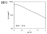
- FIG. 1 shows the relationship between the critical current density Jc of the core of the magnesium diboride superconducting wire and the external magnetic field B
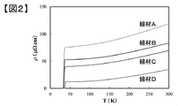
- FIG. 2 shows the temperature dependency of the electrical resistivity ⁇ .
- the wire rod was produced by PIT (powder in tube) method by using Fe as a base material.
- the PIT method is a manufacturing method in which a metal sheath is made by forming a wire by filling a metal sheath with powder and then reducing the area, and then fired.
- the permanent current switch is generally placed in a low magnetic field space of 0.5 T or less, but in a magnetic field region of 20 K or 0.5 T or less, its Jc is very high at 4000 A / mm 2 .
- the cross-sectional area required to apply a current of 400 A with Jc of 4000 A / mm 2 is 0.1 mm 2 .
- the critical temperature of magnesium diboride is 39 K
- the permanent current switch of the magnesium diboride superconducting wire is turned off, it is assumed that the wire is heated to 40 K.
- the resistivity at this time can be adjusted to 10 to 70 ⁇ cm as shown by the wires A to D in FIG. 2, the resistivity can be controlled over a fairly wide range.
- the resistivity at 40 K is 50 ⁇ cm
- the resistance per unit length is 5 ⁇ / m when the cross-sectional area of magnesium diboride is 0.1 mm 2 .
- a length of 20 cm is sufficient to obtain a resistance of 1 ohm.
- a base material is required in the outer layer of magnesium diboride in order to prevent the oxidation of magnesium diboride.
- the resistivity of the base material is preferably in the same range as magnesium diboride. For example, if the resistivity at 40 K is 50 ⁇ cm and the ratio of the cross sectional area of the base material to the cross section of the wire is about 0.5, then the resistance per unit length of the superconducting wire is 2.5 ⁇ / m. The length required to obtain 1 ⁇ resistance can be as short as 40 cm.
- the base material is preferably made of a material that does not react with magnesium. This is because the critical current density is lowered by the reaction of magnesium with the base material to reduce the amount of magnesium diboride generated during the heat treatment to form magnesium diboride.
- the best candidate for such a material is niobium titanium (resistivity at 40 K: 60 ⁇ cm). Niobium titanium is a material that hardly reacts with magnesium and has a high resistivity.
- the use of stainless steel as another base material can enhance mechanical strength.
- magnesium diboride is used for the core of the superconducting wire, and the base material is also made of a material with high resistivity such as magnesium diboride. That is, since the resistivity at 40 K of magnesium diboride is 10 ⁇ cm or more, the resistivity at 40 K of the base material is also 10 ⁇ cm or more.
- the resistivity at 40 K of magnesium diboride is 10 ⁇ cm or more
- the resistivity at 40 K of the base material is also 10 ⁇ cm or more.
- the wire Since the wire is short, the wire does not have to be wound around a conventional winding frame, and the wire may be disposed on a flat or curved plate member so that the wire does not overlap, so the shape of the wire is spiral or meander A shape etc. can also be taken.
- the wire rod is disposed between the surface of the cooling stage for turning on the switch and the heater for turning off the wire, thereby efficiently heating the portion of the wire rod that is sandwiched between the two, Since the cooling can be performed, the switch can be turned on / off quickly with less heat input.
- the cooling stage and the heater may be a flat plate, or the flat plate may be curved or may have a curved surface.
- FIG. 4 The cross-sectional view of a wire is shown in FIG. 4 and FIG.
- a double metal tube was prepared in which the inner layer was niobium titanium 5 and the outer layer was copper 4 and was filled with a mixed powder of magnesium and boron well mixed at a molar ratio of 1: 2.
- the double metal pipe was repeatedly drawn to reduce the surface to a diameter of 0.7 mm.
- the copper 4 at the outer periphery was removed by immersing the wire in nitric acid diluted to 50%.
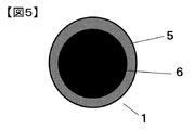
- the cross section of the wire was as shown in FIG. 5, and the diameter of the wire in which the base material 5 and the core 6 were combined was 0.5 mm in diameter.
- the critical current Ic at 20 K and 0.5 T was measured to be 600 A, which was found to be a level sufficiently applicable to the superconducting magnet.
- the temperature for turning off the permanent current switch is 40 K
- the electrical resistance per unit length at 40 K is 3 ⁇ / m, and it is found that a wire length of 33 cm is sufficient to obtain a resistivity of 1 ⁇ .
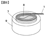
- the wire length is 33 cm, it is not necessary to wind the wire around the bobbin as in the prior art. Then, as shown in FIG. 6, it was decided to wire in a spiral on a flat plate.
- the wire rod was bent in a spiral shape, fixed to a stainless steel jig, and fired at 800 ° C. for 1 hour to form a magnesium diboride wire rod and removed from the jig.
- the wire 1 was placed on the heat resistor 7 made of FRP and was bonded with a resin. Furthermore, a film-like heater 8 with a stainless steel wire was placed on the top of the wire, and this was also fixed with resin.
- the GM refrigerator was operated to cool the permanent current switch to 20K. In this state, the permanent current switch was energized, and it was confirmed that 400 A was zero resistance.
- Second Embodiment of the Invention when not only magnesium and boron but also carbides such as SiC and B 4 C are added to the material of the core of the superconducting wire, part of B in the magnesium diboride crystal is replaced by C. Since the electron scattering center can be introduced and the resistivity at 40 K of magnesium diboride can be further increased and the resistivity per unit length of the wire can be increased, the wire length necessary for wiring of the permanent current switch can be further increased. It can be made shorter and more compact.
- magnesium diboride after forming magnesium diboride in a state of being excessively blended with magnesium.
- the remaining magnesium may be oxidized. Since magnesium oxide is an insulator and that portion does not serve as a current path, the effective cross section of magnesium diboride decreases and the resistivity increases.
- the filling rate of magnesium diboride in a typical PIT wire is about 50 to 60% by volume, and when this filling rate falls below 30% by volume, the particles of magnesium diboride become discontinuous and the continuous current path is lost
- the filling rate of magnesium oxide should be at most 20% by volume. Also, if it is 5% by volume or less, the resistivity does not increase much. Even if boron is added in excess of magnesium, the resistivity increases. Since boron alone increases in electrical resistivity at low temperatures, it has an additional role, and unreacted and residual boron also has a role of reducing the effective current path. Also in this case, the filling rate of magnesium diboride is 30% by volume or more, and the filling rate of boron is 5 to 20% by volume.
- both boron and magnesium oxide may be blended, and the total filling rate may be 5 to 20% by volume.
- the copper of the outermost layer of the wire is removed, but it is only necessary to remove the portion of the wire that is heated by the heater, and leaving the other portion allows the wire to be a heater and a heat resistor (or heater And easy to solder on the cooling stage).
- the permanent current switch obtained according to the present invention is used for a superconducting magnet which operates in a permanent current mode at about 20 K particularly by conduction cooling, so that the superconducting state and the normal conduction are not applied to the refrigerator. The state can be switched. In particular, it is effective when applied to an NMR apparatus, a medical MRI diagnostic apparatus, and the like.
Landscapes
- Physics & Mathematics (AREA)
- Condensed Matter Physics & Semiconductors (AREA)
- General Physics & Mathematics (AREA)
- Engineering & Computer Science (AREA)
- Power Engineering (AREA)
- Electromagnetism (AREA)
- Thermal Sciences (AREA)
- Containers, Films, And Cooling For Superconductive Devices (AREA)
- Magnetic Resonance Imaging Apparatus (AREA)
- Superconductors And Manufacturing Methods Therefor (AREA)
Abstract
少ない入熱で永久電流スイッチを高速にオン/オフすることが課題である。本発明は、電流を通電するための超電導線材1と、前記超電導線材を冷却する冷却ステージ9と、前記超電導線材を加熱するヒーター8とを備えた伝導冷却式永久電流スイッチにおいて、前記冷却ステージと前記ヒーターが形成する各々の面の間に前記超電導線材が配置され、前記超電導線材の芯が二ホウ化マグネシウム6であり、前記芯の外周に配置される母材5が40Kにおいて10μΩcm以上の抵抗率を有する材料である。
Description
本発明は、伝導冷却式永久電流スイッチ、MRI装置、NMR装置に関する。
NMR(核磁気共鳴分析)装置や医療用MRI(磁気共鳴イメージング)装置などのように時間的変動が極めて小さい磁場を用いる機器では、永久電流モードという運転方式が望ましい。永久電流モードとは、外部電源により超電導コイルに所定の電流を流して磁場を発生させた後、超電導コイルの正極と負極をゼロ抵抗で短絡し、外部電源の電流をゼロにすることで得られる。超電導コイルはゼロ抵抗の閉回路となるため、電流は減衰することなく超電導磁石は所定の磁場を発生し続けることができる。このとき、超電導コイルの正極と負極を短絡するための素子を永久電流スイッチという。永久電流スイッチには、次の特性が要求される。
(1)超電導コイルに流す電流と同等の電流をゼロ抵抗で通電できる。
(2)外部制御、例えばヒーター加熱により、超電導状態(オン状態)と常電導状態(オフ状態)を切り替えられる。
(3)オフ状態では高抵抗である。例えば、数オーム程度あるとよい。
(1)超電導コイルに流す電流と同等の電流をゼロ抵抗で通電できる。
(2)外部制御、例えばヒーター加熱により、超電導状態(オン状態)と常電導状態(オフ状態)を切り替えられる。
(3)オフ状態では高抵抗である。例えば、数オーム程度あるとよい。
一方、これまで液体ヘリウムに浸漬して使用してきた超電導磁石であるが、1980年代に高温超電導体が発見されるとともに、冷凍機技術の発展により、伝導冷却方式で運転することも可能になってきた。伝導冷却方式とは、冷凍機を用いて超電導磁石を熱伝導により冷却する方法である。ただし、高温超電導体の代表格である銅酸化物超電導体は、磁束クリープによる中心磁場の時間的変動が大きいため、基本的には永久電流モードで運転することはなかった。
2001年、二ホウ化マグネシウムという新たな高温超電導体が発見された。臨界温度が39Kであり、銅酸化物超電導体より臨界温度は低いものの、磁束クリープの問題が小さい。そのため、伝導冷却方式で永久電流モード運転できる超電導磁石への適用が期待されている。
伝導冷却方式の超電導磁石における永久電流スイッチでは、そのオン/オフのためのヒーターによる入熱はそのまま冷凍機の熱負荷となる。上記特許文献のものでは、冷凍機の熱負荷を低減することを考慮しているが、なるべく少ない入熱で永久電流スイッチをオン/オフすることによるスイッチングの高速化は十分考慮されていない。
本発明の目的は、少ない入熱で永久電流スイッチを高速にオン/オフすることにある。
上記目的を達成するために、本発明は、電流を通電するための超電導線材と、前記超電導線材を冷却する冷却ステージと、前記超電導線材を加熱するヒーターとを備えた伝導冷却式永久電流スイッチにおいて、前記冷却ステージと前記ヒーターが形成する各々の面の間に前記超電導線材が配置され、前記超電導線材の芯が二ホウ化マグネシウムであり、前記芯の外周に配置される母材が40Kにおいて10μΩcm以上の抵抗率を有する材料であることを特徴とする。
本発明によれば、少ない入熱で永久電流スイッチを高速にオン/オフすることができる。
発明者らは、二ホウ化マグネシウム超電導線材を高性能化する過程で、この超電導線材が極めて伝導冷却方式の永久電流スイッチに適していることを見出した。
優れた永久電流スイッチ用の超電導線材とは、オン状態において必要とされる超電導電流(例えば典型的な値として400Aとしよう)を通電でき、オフ状態における線材単位長さあたりの抵抗値ができる限り高いものがよい。このような線材を用いれば、永久電流スイッチに使用する線材を短くすることができ、その結果永久電流スイッチの熱容量の低減につながる。
本発明は、特に、NMR装置や医療用MRI診断装置などに用いられ、永久電流モードで運転する超電導磁石に適用できる。
図1は二ホウ化マグネシウム超電導線材の芯の臨界電流密度Jcと外部磁場Bとの関係、図2はその電気抵抗率ρの温度依存性である。なお、線材は、Feを母材としてPIT(パウダー・イン・チューブ)法により作製した。PIT法とは、金属シースに粉末を充填した後に減面加工することで線材化し、焼成する製造方法である。
永久電流スイッチは一般的には0.5T以下の低磁場の空間に設置されるが、20K、0.5T以下の磁場領域では、そのJcは4000A/mm2と非常に高い。例えば、Jcを4000A/mm2として400Aの電流を通電するのに必要な断面積は0.1mm2となる。
一方、二ホウ化マグネシウムの臨界温度が39Kであることから、二ホウ化マグネシウム超電導線材の永久電流スイッチをオフにする場合は、線材を40Kに加熱することが想定される。このときの抵抗率は、図2の線材A~Dに示すように10~70μΩcmに調整することができるので、かなり広い範囲に渡って制御可能である。例えば、40Kにおける抵抗率が50μΩcmのものを用いると、二ホウ化マグネシウムの断面積0.1mm2としたときの単位長さあたりの抵抗は5Ω/mである。従って、例えば1Ωの抵抗を得るのに必要な長さは20cmで十分である。
実際には、PIT法で線材を作製する場合には、二ホウ化マグネシウムの酸化を防止するために、二ホウ化マグネシウムの外層に母材が必要になる。母材の抵抗率は二ホウ化マグネシウムと同程度の範囲のものが好ましい。例えば40Kにおける抵抗率が50μΩcmを用い、さらに線材の断面において母材の断面積が占める割合を0.5程度とすれば、超電導線材の単位長さあたりの抵抗は2.5Ω/mとなり、例えば1Ωの抵抗を得るのに必要な長さは40cm程度と非常に短くてすむ。
母材は、マグネシウムと反応しないような材質であるのが好ましい。二ホウ化マグネシウムを生成させる熱処理のときに、マグネシウムが母材と反応して二ホウ化マグネシウムの生成量が減ることによって、臨界電流密度が低下してしまうためである。このような材料の最も良い候補としては、ニオブチタン(40Kでの抵抗率:60μΩcm)が挙げられる。ニオブチタンは、マグネシウムと反応しにくく、抵抗率が高い材料である。その他の母材としてステンレス鋼を用いると、機械的な強度を増強することができる。
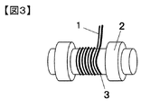
液体ヘリウムに浸漬して冷却する永久電流スイッチであって、線材の芯をニオブチタンとする場合は、線材の長さが10m程度も必要であるため、線材1をヒーター線2と一緒に巻き枠3に巻いた構造が一般的である(図3)。しかし、本発明では線材の長さが数十cmなので巻き枠なしの構造も可能になる。通常、永久電流スイッチでは熱容量の大部分を巻き枠が占めるため、それを撤廃することにより永久電流スイッチの熱容量を極めて小さくすることが可能になる。
本発明では、超電導線材の芯に二ホウ化マグネシウムを用いて、その母材も二ホウ化マグネシウムのような高抵抗率の材質とする。即ち、二ホウ化マグネシウムの40Kにおける抵抗率が10μΩcm以上であることから、母材の40Kにおける抵抗率も10μΩcm以上のものを用いる。このような線材にすることにより、永久電流スイッチをオフにするために必要な数オームの抵抗を、断面積が小さく長さが短い線材で実現できる。
線材が短いので、従来のような巻き枠に線材を巻き回さなくてもよく、平面又は曲面の板部材上に線材が重ならないように配置すればよいので、配線の形状は螺旋状や蛇行形状等もとりうる。線材はスイッチをオン状態にするための冷却ステージと、オフ状態にするためのヒーターとの面間に配置されることで、線材の中で両者に挟まれている部分の線材を効率良く加熱、冷却できるため、少ない入熱でスイッチを高速にオン/オフすることができる。本発明では、冷却ステージとヒーターの面の間に線材が挟まれる構造であればよいので、冷却ステージとヒーターは平板でも、平板が湾曲していても、曲面を形成していてもよい。ただし、ある一点から板部材(冷却ステージ又はヒーター)を見たときに、ある一点から板部材上に配置された全ての線材が見渡せる程度の湾曲又は曲面に留めておくのがよい。
(発明を実施する第1の形態)
図4と図5に線材の断面図を示す。内層がニオブチタン5、外層が銅4の二重金属管を準備し、1:2のmol比率でよく混合したマグネシウムとホウ素の混合粉末を充填した。次いで、二重金属管を繰り返し引抜加工することで減面してφ0.7mmの直径にした。この線材を50%に希釈した硝酸に浸漬することで、外周の銅4を除去した。このとき、線材断面は図5のようになり、母材5と芯6を併せた線材直径はφ0.5mmとなった。
(発明を実施する第1の形態)
図4と図5に線材の断面図を示す。内層がニオブチタン5、外層が銅4の二重金属管を準備し、1:2のmol比率でよく混合したマグネシウムとホウ素の混合粉末を充填した。次いで、二重金属管を繰り返し引抜加工することで減面してφ0.7mmの直径にした。この線材を50%に希釈した硝酸に浸漬することで、外周の銅4を除去した。このとき、線材断面は図5のようになり、母材5と芯6を併せた線材直径はφ0.5mmとなった。
線材を800℃で1hr焼成した後、20K、0.5Tの臨界電流Icを測定すると600Aであり、超電導磁石に十分適用可能なレベルであることがわかった。一方、永久電流スイッチをオフにするための温度を40Kとすると、40Kにおける単位長さあたりの電気抵抗は3Ω/mであり、1Ωの抵抗率を得るのに33cmの線材長でよいことがわかった。
線材長が33cmであれば、従来のようにボビンに線材を巻く必要がない。そこで、図6に示すように、平板上に螺旋状に配線することとした。線材を螺旋状に曲げた後に、ステンレス製の治具に固定して、800℃で1hr焼成することで、二ホウ化マグネシウムの線材を生成させ、治具から取り外した。本実施形態では、FRP製の熱抵抗体7の上に線材1を設置し、樹脂で接着した。さらに線材の上部に、ステンレスの配線がされたフィルム状のヒーター8を載せてこれも樹脂で固定した。
これらを真空断熱されたクライオスタット内の20KGM(Gifford-MacMahon)冷凍機の冷却ステージ9の上に取り付けた。熱抵抗体をヒーターと冷却ステージとの間に設けることにより、ヒーター8で線材1を加熱したときに、冷却ステージに伝わる量を低減することができる。FRPの他に樹脂を用いてもよい。
GM冷凍機を運転して、永久電流スイッチを20Kに冷却した。この状態で永久電流スイッチに通電し、400Aを抵抗ゼロであることを確認した。次いで、ヒーター8を1Wの入力で加熱した状態で、永久電流スイッチに100mAの電流を通電して発生電圧を計測することで、その抵抗を測定すると1.3Ωの抵抗が得られ、1Wの入力で十分に永久電流スイッチとして機能することを確認した。
(発明を実施する第2の形態)
本実施形態では、超電導線材の芯の原料にマグネシウムとホウ素だけでなく、SiC、B4Cなどの炭化物を添加すると、二ホウ化マグネシウムの結晶におけるBの一部がCに置換されることで電子散乱中心が導入され、二ホウ化マグネシウムの40Kにおける抵抗率がさらに増大され、線材の単位長さあたりの抵抗率を増大させることができるので、永久電流スイッチの配線に必要な線長をさらに短くできて、よりコンパクトにすることができる。
二ホウ化マグネシウムの結晶におけるBの一部がCに置換されると、X線回折により評価される結晶のa軸長がCの実効置換量に応じて短くなることが知られている。一方、C置換量が増大すると二ホウ化マグネシウムが超電導状態を維持できる温度(臨界温度Tc)が低下するので、その臨界電流密度が不足する事態が生じる。そこで、炭化物の添加量は、a軸長が0.3062~0.3080nmの範囲にあるように調整するのがよい。
(発明を実施する第3の形態)
二ホウ化マグネシウムの40Kにおける抵抗率をさらに増大させるのに、マグネシウムを余分に配合した状態で二ホウ化マグネシウムを生成させた後に、200℃程度の温度で大気中加熱することで、反応せず残留したマグネシウムを酸化させてもよい。酸化マグネシウムは絶縁体であり、その部分は電流経路とならないため、実効的な二ホウ化マグネシウムの断面積が減少して抵抗率が増大する。
(発明を実施する第3の形態)
二ホウ化マグネシウムの40Kにおける抵抗率をさらに増大させるのに、マグネシウムを余分に配合した状態で二ホウ化マグネシウムを生成させた後に、200℃程度の温度で大気中加熱することで、反応せず残留したマグネシウムを酸化させてもよい。酸化マグネシウムは絶縁体であり、その部分は電流経路とならないため、実効的な二ホウ化マグネシウムの断面積が減少して抵抗率が増大する。
典型的なPIT線材の二ホウ化マグネシウムの充填率は50~60体積%程度であり、この充填率が30体積%より低下すると二ホウ化マグネシウムの粒子が不連続となり、連続した電流経路が失われるので、酸化マグネシウムの充填率は多くても20体積%とするのがよい。また、5体積%以下であると抵抗率はあまり増加しない。
マグネシウムを余分に配合する代わりにホウ素を余分に配合しても抵抗率が増加する。ホウ素単体は低温で電気抵抗率が増大するため、余分に配合して、反応せず残留したホウ素も実効的な電流路を減少させる役割をもつ。この場合も二ホウ化マグネシウムの充填率は30体積%以上、ホウ素の充填率は5~20体積%とする。また、ホウ素と酸化マグネシウムの両方を配合し、合計の充填率を5~20体積%としてもよい。
(発明を実施する第4の形態)
第1の形態では線材の最外層の銅を除去したが、これを除去するのはヒーター加熱する部分だけでよく、それ以外の部分を残しておくと、線材をヒーターと熱抵抗体(またはヒーターと冷却ステージ)に半田付けしやすくなる。
(発明を実施する第5の形態)
本発明で得られた永久電流スイッチは、特に伝導冷却により20K程度で永久電流モード運転するような超電導磁石に用いることで、冷凍機に対して大きな熱負荷をかけることなく、超電導状態と常電導状態を切換えることができる。特に、NMR装置、医療用MRI診断装置などに適用すると有効である。
1・・・線材
2・・・ヒーター線
3・・・巻き枠
4・・・銅
5・・・ニオブチタン(母材)
6・・・二ホウ化マグネシウム(芯)
7・・・熱抵抗体
8・・・ヒーター
9・・・冷却ステージ
2・・・ヒーター線
3・・・巻き枠
4・・・銅
5・・・ニオブチタン(母材)
6・・・二ホウ化マグネシウム(芯)
7・・・熱抵抗体
8・・・ヒーター
9・・・冷却ステージ
Claims (10)
- 電流を通電するための超電導線材と、前記超電導線材を冷却する冷却ステージと、前記超電導線材を加熱するヒーターとを備えた伝導冷却式永久電流スイッチにおいて、
前記冷却ステージと前記ヒーターが形成する各々の面の間に前記超電導線材が配置され、前記超電導線材の芯が二ホウ化マグネシウムであり、前記芯の外周に配置される母材が40Kにおいて10μΩcm以上の抵抗率を有する材料であることを特徴とする伝導冷却式永久電流スイッチ。 - 請求項1において、前記冷却ステージと前記線材との間に熱抵抗体が配置されることを特徴とする伝導冷却式永久電流スイッチ。
- 請求項1において、前記母材がニオブチタンまたはステンレス鋼であることを特徴とする伝導冷却式永久電流スイッチ。
- 請求項2において、前記熱抵抗体が樹脂またはFRPであることを特徴とする、伝導冷却式永久電流スイッチ。
- 請求項1において、前記二ホウ化マグネシウムの結晶構造のa軸長が0.3062~0.3080nmの範囲にあることを特徴とする伝導冷却式永久電流スイッチ。
- 請求項1において、前記芯に酸化マグネシウムが含まれることを特徴とする伝導冷却式永久電流スイッチ。
- 請求項1において、前記母材の一部の外周に銅を配置し、前記銅を介して前記線材と前記ヒーター、前記線材と前記冷却ステージとを接続することを特徴とする伝導冷却式永久電流スイッチ。
- 請求項2において、前記母材の一部の外周に銅を配置し、前記銅を介して前記線材と前記ヒーター、前記線材と前記熱抵抗体とを接続することを特徴とする伝導冷却式永久電流スイッチ。
- 請求項1に記載の伝導冷却式永久電流スイッチを備えたMRI装置。
- 請求項1に記載の伝導冷却式永久電流スイッチを備えたNMR装置。
Priority Applications (1)
| Application Number | Priority Date | Filing Date | Title |
|---|---|---|---|
| US14/421,470 US9887029B2 (en) | 2012-08-29 | 2013-07-12 | Conductive cooling-type persistent current switch, MRI apparatus and NMR apparatus |
Applications Claiming Priority (2)
| Application Number | Priority Date | Filing Date | Title |
|---|---|---|---|
| JP2012188208A JP6047341B2 (ja) | 2012-08-29 | 2012-08-29 | 伝導冷却式永久電流スイッチ及び超電導線材の製造方法 |
| JP2012-188208 | 2012-08-29 |
Publications (1)
| Publication Number | Publication Date |
|---|---|
| WO2014034295A1 true WO2014034295A1 (ja) | 2014-03-06 |
Family
ID=50183115
Family Applications (1)
| Application Number | Title | Priority Date | Filing Date |
|---|---|---|---|
| PCT/JP2013/069090 WO2014034295A1 (ja) | 2012-08-29 | 2013-07-12 | 伝導冷却式永久電流スイッチ、mri装置、nmr装置 |
Country Status (3)
| Country | Link |
|---|---|
| US (1) | US9887029B2 (ja) |
| JP (1) | JP6047341B2 (ja) |
| WO (1) | WO2014034295A1 (ja) |
Cited By (2)
| Publication number | Priority date | Publication date | Assignee | Title |
|---|---|---|---|---|
| EP3327733A4 (en) * | 2015-07-24 | 2019-03-06 | Hitachi, Ltd. | SUPERCONDUCTING WIRE, SUPER-CHARGE COIL, MRI AND NMR |
| WO2021054094A1 (ja) | 2019-09-20 | 2021-03-25 | 住友電気工業株式会社 | 永久電流スイッチ及び超電導装置 |
Families Citing this family (2)
| Publication number | Priority date | Publication date | Assignee | Title |
|---|---|---|---|---|
| JP6453185B2 (ja) * | 2015-08-19 | 2019-01-16 | 株式会社日立製作所 | 超電導磁石装置または磁気共鳴イメージング装置 |
| JP2021136341A (ja) * | 2020-02-27 | 2021-09-13 | 株式会社日立製作所 | 超電導マグネット、超電導線材および超電導マグネットの生産方法 |
Citations (6)
| Publication number | Priority date | Publication date | Assignee | Title |
|---|---|---|---|---|
| JPH01137557U (ja) * | 1988-03-15 | 1989-09-20 | ||
| JPH08190817A (ja) * | 1995-01-06 | 1996-07-23 | Hitachi Ltd | 超電導装置および超電導装置に用いられる永久電流スイッチ素子およびその超電導線材並びに超電導線材の製造方法 |
| JP2003069093A (ja) * | 2001-08-29 | 2003-03-07 | Central Japan Railway Co | 永久電流スイッチおよびそれを用いた超電導マグネット |
| JP2005529832A (ja) * | 2002-06-18 | 2005-10-06 | ユニヴァーシティ・オブ・ウロンゴン | 超伝導物質および合成方法 |
| JP2006228797A (ja) * | 2005-02-15 | 2006-08-31 | Hitachi Ltd | 二硼化マグネシウムを用いた永久電流スイッチおよびその製造方法 |
| JP2007221013A (ja) * | 2006-02-20 | 2007-08-30 | Hitachi Ltd | 永久電流スイッチ |
Family Cites Families (11)
| Publication number | Priority date | Publication date | Assignee | Title |
|---|---|---|---|---|
| US3359394A (en) * | 1966-05-02 | 1967-12-19 | Gen Electric | Persistent current switch |
| JP2508159B2 (ja) | 1987-11-25 | 1996-06-19 | 岩崎電気株式会社 | 金属蒸気放電灯 |
| US5361055A (en) * | 1993-12-17 | 1994-11-01 | General Dynamics Corporation | Persistent protective switch for superconductive magnets |
| JP2004179413A (ja) | 2002-11-27 | 2004-06-24 | Mitsubishi Electric Corp | 冷却型超電導磁石装置 |
| JP4456016B2 (ja) * | 2005-02-04 | 2010-04-28 | 株式会社日立製作所 | 金属シース二ホウ化マグネシウム超電導線材及びその製造方法 |
| JP4533254B2 (ja) * | 2005-06-21 | 2010-09-01 | 株式会社日立製作所 | 金属面の接合方法 |
| JP4790752B2 (ja) * | 2008-04-28 | 2011-10-12 | 株式会社日立製作所 | 超電導マグネット |
| JP5519430B2 (ja) * | 2010-06-30 | 2014-06-11 | 株式会社日立製作所 | MgB2超電導線材の製造方法 |
| US8922308B2 (en) * | 2011-10-31 | 2014-12-30 | General Electric Company | Systems and methods for alternatingly switching a persistent current switch between a first mode and a second mode |
| KR101351586B1 (ko) * | 2012-03-12 | 2014-01-15 | 삼성전자주식회사 | 영구 스위치 제어 시스템, 이를 채용한 초전도 자석 장치 및 영구 스위치 제어 방법 |
| JP2013197072A (ja) * | 2012-03-23 | 2013-09-30 | Hitachi Ltd | MgB2超電導多芯線材、超電導ケーブル、超電導マグネット |
-
2012
- 2012-08-29 JP JP2012188208A patent/JP6047341B2/ja active Active
-
2013
- 2013-07-12 US US14/421,470 patent/US9887029B2/en active Active
- 2013-07-12 WO PCT/JP2013/069090 patent/WO2014034295A1/ja active Application Filing
Patent Citations (6)
| Publication number | Priority date | Publication date | Assignee | Title |
|---|---|---|---|---|
| JPH01137557U (ja) * | 1988-03-15 | 1989-09-20 | ||
| JPH08190817A (ja) * | 1995-01-06 | 1996-07-23 | Hitachi Ltd | 超電導装置および超電導装置に用いられる永久電流スイッチ素子およびその超電導線材並びに超電導線材の製造方法 |
| JP2003069093A (ja) * | 2001-08-29 | 2003-03-07 | Central Japan Railway Co | 永久電流スイッチおよびそれを用いた超電導マグネット |
| JP2005529832A (ja) * | 2002-06-18 | 2005-10-06 | ユニヴァーシティ・オブ・ウロンゴン | 超伝導物質および合成方法 |
| JP2006228797A (ja) * | 2005-02-15 | 2006-08-31 | Hitachi Ltd | 二硼化マグネシウムを用いた永久電流スイッチおよびその製造方法 |
| JP2007221013A (ja) * | 2006-02-20 | 2007-08-30 | Hitachi Ltd | 永久電流スイッチ |
Cited By (4)
| Publication number | Priority date | Publication date | Assignee | Title |
|---|---|---|---|---|
| EP3327733A4 (en) * | 2015-07-24 | 2019-03-06 | Hitachi, Ltd. | SUPERCONDUCTING WIRE, SUPER-CHARGE COIL, MRI AND NMR |
| US11127514B2 (en) | 2015-07-24 | 2021-09-21 | Hitachi, Ltd. | Superconducting wire, superconducting coil, MRI and NMR |
| WO2021054094A1 (ja) | 2019-09-20 | 2021-03-25 | 住友電気工業株式会社 | 永久電流スイッチ及び超電導装置 |
| US11980106B2 (en) | 2019-09-20 | 2024-05-07 | Sumitomo Electric Industries, Ltd. | Persistent current switch and superconducting device |
Also Published As
| Publication number | Publication date |
|---|---|
| US20150228391A1 (en) | 2015-08-13 |
| US9887029B2 (en) | 2018-02-06 |
| JP2014045158A (ja) | 2014-03-13 |
| JP6047341B2 (ja) | 2016-12-21 |
Similar Documents
| Publication | Publication Date | Title |
|---|---|---|
| WO2010140398A1 (ja) | 冷凍機冷却型超電導磁石 | |
| JP5276542B2 (ja) | 超電導回路、超電導接続部の作製方法、超電導マグネット、及び、超電導マグネットの製造方法 | |
| US8385994B2 (en) | Superconducting joint and method for manufacturing same | |
| JP2007221013A (ja) | 永久電流スイッチ | |
| JP4391403B2 (ja) | 二ホウ化マグネシウム超電導線の接続構造及びその接続方法 | |
| US20100245005A1 (en) | Superconducting wire rod, persistent current switch, and superconducting magnet | |
| JP6666274B2 (ja) | 高温超電導永久電流スイッチ及び高温超電導磁石装置 | |
| WO2014034295A1 (ja) | 伝導冷却式永久電流スイッチ、mri装置、nmr装置 | |
| JP4728007B2 (ja) | 二硼化マグネシウムを用いた永久電流スイッチおよびその製造方法 | |
| US6809618B2 (en) | Switching device for superconducting technology | |
| JP2003037303A (ja) | ニホウ化マグネシウム超電導線材を用いた永久電流スイッチ付超電導コイルおよびその製造方法 | |
| JP5011181B2 (ja) | 酸化物超電導電流リード | |
| JP4477859B2 (ja) | 永久電流スイッチ、超電導磁石及び磁気共鳴イメージング装置 | |
| JP2019160818A (ja) | 高温超電導磁石装置、その運転制御装置及び方法 | |
| JP5603297B2 (ja) | 超電導マグネット及びその製造方法 | |
| US20170040095A1 (en) | Superconducting device and method for inducing low relaxation rate in superconducting material | |
| JP2009004794A (ja) | 永久電流スイッチ | |
| JP3734630B2 (ja) | 伝導冷却型超電導磁石装置 | |
| Cui et al. | Design and test of superconducting persistent current switch for experimental Nb 3 Sn superconducting magnet | |
| JP2002260463A (ja) | 粉末法Nb▲3▼Sn超電導線材による超電導接続構造体の製造方法 | |
| US20240045009A1 (en) | Superconducting magnet apparatus, magnetic resonance imaging apparatus, and method for demagnetizing superconducting magnet | |
| JP2013093401A (ja) | 超電導マグネット及びその製造方法 | |
| JP2017208156A (ja) | 超電導線材の接続部及び超電導線材の接続方法 | |
| JP2859953B2 (ja) | 超電導装置及び該超電導装置に使用する永久電流スイツチ | |
| WO2023105974A1 (ja) | 超電導コイル装置 |
Legal Events
| Date | Code | Title | Description |
|---|---|---|---|
| 121 | Ep: the epo has been informed by wipo that ep was designated in this application |
Ref document number: 13834033 Country of ref document: EP Kind code of ref document: A1 |
|
| WWE | Wipo information: entry into national phase |
Ref document number: 14421470 Country of ref document: US |
|
| NENP | Non-entry into the national phase |
Ref country code: DE |
|
| 122 | Ep: pct application non-entry in european phase |
Ref document number: 13834033 Country of ref document: EP Kind code of ref document: A1 |