WO2014030741A1 - 前後連動ブレーキ機構 - Google Patents
前後連動ブレーキ機構 Download PDFInfo
- Publication number
- WO2014030741A1 WO2014030741A1 PCT/JP2013/072555 JP2013072555W WO2014030741A1 WO 2014030741 A1 WO2014030741 A1 WO 2014030741A1 JP 2013072555 W JP2013072555 W JP 2013072555W WO 2014030741 A1 WO2014030741 A1 WO 2014030741A1
- Authority
- WO
- WIPO (PCT)
- Prior art keywords
- cable
- link
- rear wheel
- brake
- holder
- Prior art date
- Legal status (The legal status is an assumption and is not a legal conclusion. Google has not performed a legal analysis and makes no representation as to the accuracy of the status listed.)
- Ceased
Links
Images













Classifications
-
- B—PERFORMING OPERATIONS; TRANSPORTING
- B62—LAND VEHICLES FOR TRAVELLING OTHERWISE THAN ON RAILS
- B62L—BRAKES SPECIALLY ADAPTED FOR CYCLES
- B62L3/00—Brake-actuating mechanisms; Arrangements thereof
- B62L3/02—Brake-actuating mechanisms; Arrangements thereof for control by a hand lever
- B62L3/023—Brake-actuating mechanisms; Arrangements thereof for control by a hand lever acting on fluid pressure systems
-
- B—PERFORMING OPERATIONS; TRANSPORTING
- B62—LAND VEHICLES FOR TRAVELLING OTHERWISE THAN ON RAILS
- B62K—CYCLES; CYCLE FRAMES; CYCLE STEERING DEVICES; RIDER-OPERATED TERMINAL CONTROLS SPECIALLY ADAPTED FOR CYCLES; CYCLE AXLE SUSPENSIONS; CYCLE SIDECARS, FORECARS, OR THE LIKE
- B62K23/00—Rider-operated controls specially adapted for cycles, i.e. means for initiating control operations, e.g. levers, grips
- B62K23/02—Rider-operated controls specially adapted for cycles, i.e. means for initiating control operations, e.g. levers, grips hand actuated
- B62K23/06—Levers
-
- B—PERFORMING OPERATIONS; TRANSPORTING
- B62—LAND VEHICLES FOR TRAVELLING OTHERWISE THAN ON RAILS
- B62L—BRAKES SPECIALLY ADAPTED FOR CYCLES
- B62L3/00—Brake-actuating mechanisms; Arrangements thereof
- B62L3/02—Brake-actuating mechanisms; Arrangements thereof for control by a hand lever
-
- B—PERFORMING OPERATIONS; TRANSPORTING
- B62—LAND VEHICLES FOR TRAVELLING OTHERWISE THAN ON RAILS
- B62L—BRAKES SPECIALLY ADAPTED FOR CYCLES
- B62L3/00—Brake-actuating mechanisms; Arrangements thereof
- B62L3/08—Mechanisms specially adapted for braking more than one wheel
Definitions
- the present invention relates to a front / rear interlocking brake mechanism in which a front wheel side brake and a rear wheel side brake of a two-wheeled vehicle operate in conjunction with each other.
- the first type is a type in which a front-wheel brake is operated by a right-hand lever operation and a rear-wheel brake is operated by a left-hand lever operation.
- the second type is a type in which the front-wheel brake is activated by the lever operation on the right-hand side, and the rear-wheel brake is activated by the operation of the foot pedal on the right foot side.
- Patent Literature 1 discloses a technique in which the front wheel side brake and the rear wheel side brake are operated in conjunction with either left or right lever operation.
- Patent Document 1 relates to a brake for a motorcycle that does not require clutch operation, such as a scooter.
- the front wheel brake is configured to operate by a hydraulic operation by pressing a piston of a master cylinder.
- the rear wheel brake is configured to operate by a cable pulling operation.
- the front wheel link 3 disposed so as to be swingable with respect to the rotating shaft 2 of the brake lever 1 and the rotating shaft 2 of the brake lever 1 are separated from each other.
- the rear wheel link 4 pivotally supported by a link point provided at a position is a main component.
- An inner cable 6a of a rear wheel brake cable 6 fixed to an anchor 5a of the master cylinder 5 is fixed to the front end of the rear wheel link 4, and the other brake is connected to a pressing side end portion of the master cylinder 5 in the front wheel link 3.
- An operation cable (not shown) for transmitting the operation state of the lever is connected.
- the rear wheel link 4 moves in the direction of arrow E around the rotation shaft 2.
- the rear wheel link 4 is rotated relative to the brake lever 1 and presses a part of the front wheel link 3.
- the front wheel link 3 rotates in the direction of the arrow F with the rotation shaft 2 as a base point, and presses the master cylinder 5.
- a bracket portion for fixing a cable or the like is formed integrally with the master cylinder in order to constitute an interlocking brake, and it is necessary to newly design the master cylinder itself.
- the first object of the present invention is to provide a front-rear interlocking brake mechanism that can establish an interlocking brake even when the master cylinder is arranged on the right side with respect to the viewpoint from the operation side. To do.
- an object of the present invention is to provide a front-rear interlocking brake mechanism that can solve at least one of the above-mentioned problems.
- a front-rear interlocking brake mechanism configured by interposing a link mechanism between a master cylinder for operating a front wheel side brake and one brake lever, A first inner cable that is an inner cable of a rear wheel brake cable is connected, and a rear wheel link that pulls the first inner cable by moving together with a fixed shaft; A second inner cable that is an inner cable of a transmission cable that is pulled by operating either one of the other brake lever or the foot pedal is connected, and is rotated by the pulling of the second inner cable to rotate the rear wheel.
- a front-rear interlocking brake mechanism comprising: a holder for moving the fixed shaft of the link.
- a front-rear interlocking brake mechanism having the configuration of (1) above, wherein a cable anchor that prevents movement of the entire cable accompanying towing is provided, and a bracket that is configured separately from the master cylinder is provided.
- the front-rear interlocking brake mechanism can be added only by assembling the accessory parts while adopting a master cylinder common to the inexpensive brake mechanism in which the front-rear interlocking brake mechanism is not mounted. Therefore, the front / rear interlocking brake mechanism can be added easily and inexpensively.
- Both the anchor position of the first outer cable and the connection position of the first inner cable, and the anchor position of the second outer cable and the connection position of the second inner cable are both the master cylinder and the rear wheel.
- the front / rear interlocking brake mechanism having the configuration of (2) above, wherein the link, the holder, the bracket, and the one brake lever are arranged at positions exposed to the outer periphery. According to the configuration as described in (3) above, the cables can be routed after the front wheel link, the rear wheel link, and the holder are assembled to the master cylinder.
- the connecting portion between the first inner cable and the rear wheel link is disposed on the same plane as the operation plane of the one brake lever, A connecting portion between the second inner cable and the holder is removed from the operation plane, and a shaft hole for inserting a connecting bolt serving as an operation rotating shaft of the one brake lever is provided in the second inner cable.
- a front-rear interlocking brake mechanism having any one of the constitutions (1) to (3) provided on a plate piece on which a connecting portion between the holder and the holder is disposed. According to the configuration as described in (4) above, the plan view configuration of the front / rear interlocking brake mechanism can be reduced.
- a rotation prevention mechanism for preventing the rear wheel link from rotating from the fixed shaft to a side opposite to the moving direction of the fixed shaft is provided between the rear wheel link and the holder.
- a cam portion that comes into contact with the rear wheel link is provided, and the master portion rotates when the one brake lever is operated or when the cam portion is pressed by the rear wheel link. It has a front wheel link that presses the piston of the cylinder,
- the front-rear interlocking brake mechanism configured as described in (6) above, wherein the rear wheel link is in a non-braking state and is in contact with the cam portion and the rotation prevention mechanism is functioning. According to the above feature (7), even if the rear wheel link is in a normal state or an abnormal state in which the hydraulic pressure of the master cylinder has failed, a lever operation during braking or a pedal In operation, it is possible to operate the rear wheel side brake with less variation in stroke.
- the front / rear interlocking brake mechanism having the configuration as described in (1) to (8) above, even if the master cylinder is arranged on the right side with respect to the viewpoint from the operation side, the front / rear interlocking brake mechanism is Can be established.
- FIG. 1 is a plan view showing a configuration of a front / rear interlocking brake mechanism according to a first embodiment of the present invention.
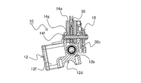
- FIG. 2 is a view showing a II-II cross section in FIG.
- FIG. 3 is a bottom perspective view showing the configuration of the front / rear interlocking brake mechanism according to the first embodiment.
- FIG. 4 is a schematic diagram showing the configuration of the entire brake mechanism.
- FIG. 5 is a partially exploded perspective view showing a state where the bracket, the front wheel link, the rear wheel link, the holder, and one brake lever are detached from the master cylinder.
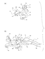
- 6A and 6B are partially exploded perspective views showing the structure of the link mechanism portion, and FIG. 6A is a detailed exploded perspective view of the link mechanism portion, and FIG. FIG.
- FIG. 3 is an exploded perspective view of a bracket, a link mechanism, and one brake lever.
- FIG. 7 is a partial sectional plan view showing the configuration of the link mechanism.
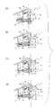
- FIGS. 8A to 8D are diagrams for explaining the operation of the front / rear interlocking brake mechanism.
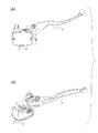
- FIGS. 9A and 9B are a plan view and a bottom perspective view showing a state in which a normal brake lever is assembled to the master cylinder used in the first embodiment.
- FIG. 10 is an exploded top perspective view of the front wheel link, the rear wheel link, the bracket, the holder, and one brake lever in the applied form of the front / rear interlocking brake mechanism according to the first embodiment.
- FIG. 10 is an exploded top perspective view of the front wheel link, the rear wheel link, the bracket, the holder, and one brake lever in the applied form of the front / rear interlocking brake mechanism according to the first embodiment.
- FIG. 11 is an exploded perspective view of the lower surface side of the front wheel link, the rear wheel link, the bracket, the holder, and one brake lever in the application form of the front / rear interlocking brake mechanism according to the first embodiment.
- FIG. 12 is a top perspective view showing the configuration of the front / rear interlocking brake mechanism in the application mode.
- FIG. 13 is a plan view showing the configuration of the front / rear interlocking brake mechanism according to the second embodiment.
- FIG. 14 is a view showing a cross-section XIV-XIV in FIG.
- FIG. 15 is a bottom perspective view showing the configuration of the front / rear interlocking brake mechanism according to the second embodiment.
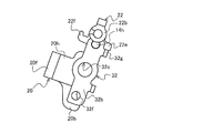
- FIG. 16 is a plan view showing details of the link mechanism according to the second embodiment.
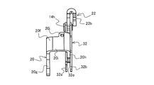
- FIG. 17 is a right side view showing details of the link mechanism according to the second embodiment.
- FIG. 18 is a bottom view showing details of the link mechanism according to the second embodiment.
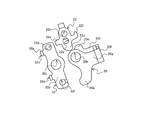
- FIG. 19 is an exploded view showing individual components of the link mechanism according to the second embodiment.
- 20A to 20D are views for explaining the operation of the front / rear interlocking brake mechanism according to the second embodiment.
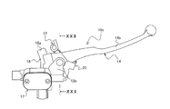
- FIG. 21 is a plan view showing a configuration as a first application mode of the front / rear interlocking brake mechanism according to the second embodiment.
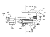
- FIG. 22 is a view showing a section XXII-XXII in FIG.
- FIG. 23 is a bottom view showing a configuration as a first application mode of the front / rear interlocking brake mechanism according to the second embodiment.
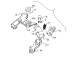
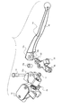
- FIG. 24 is a partially exploded perspective view showing a state in which the bracket, front wheel link, rear wheel link, holder, and one brake lever of the front / rear interlocking brake mechanism shown in FIG. 21 are removed from the master cylinder.
- FIG. 25 is a front view showing the configuration of the link mechanism portion.
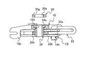
- 26 is a view showing a section XXVI-XXVI of the link mechanism portion shown in FIG. 27 is an exploded perspective view of the link mechanism portion shown in FIG.
- FIG. 28 is a front view showing a configuration as a second application mode of the front-rear interlocking brake mechanism according to the second embodiment.
- FIG. 29 is a view showing a section XIX-XXIX in FIG.
- FIG. 30 is a partially exploded perspective view showing a state in which the front wheel link, the rear wheel link, the holder, and one brake lever of the front / rear interlocking brake mechanism shown in FIG. 28 are removed from the master cylinder.
- FIG. 31 is an exploded perspective view of a link mechanism portion according to the second application mode.
- FIG. 32 is a diagram showing a configuration of a conventional front / rear interlocking brake mechanism.
- the brake mechanism according to the present invention is a cable in which the front wheel side brake 104 is operated by a hydraulic mechanism via the master cylinder 12 and connected to the brake operation mechanism on the rear wheel side.
- the rear wheel side brake 106 is actuated by pulling the wheel.
- the first embodiment is intended for two-wheeled vehicles (mainly motorcycles).
- a pair of grip portions 102a and 102b in the handle 100 are provided with one brake lever 14 and the other.
- the brake lever 16 is provided.
- the one brake lever 14 and the other brake lever 16 here are not limited to being attached to either of the left and right grip portions 102a and 102b, but in the first embodiment.
- the brake lever attached to the master cylinder 12, which will be described in detail later, that is, the brake lever attached to the right grip 102 b is referred to as one brake lever 14.
- the master cylinder 12 As shown in FIGS. 1 to 3, on the grip portion 102b side where one brake lever 14 is arranged, in addition to the brake lever (one brake lever 14), the master cylinder 12, the bracket 18, the holder 30, the front wheel A link 20 and a rear wheel link 22 are arranged.
- the master cylinder 12 is an operation source of a hydraulic mechanism for operating the front wheel side brake 104.
- the master cylinder 12 includes a master cylinder body 12a, a piston 12b, a spring 12c, an attachment portion 12d, and a lever assembly portion 12e.
- the master cylinder body 12a is an element constituting a cylinder for pressure-feeding fluid, and a fluid tank 12f for making up for the insufficient fluid by pushing out a caliper side piston (not shown) is integrally formed (see FIG. 5).
- the piston 12b is a pressing element for pumping fluid stored in a cylinder formed in the master cylinder body 12a.
- the piston 12b is disposed in the cylinder, and is pressed into the cylinder by receiving pressure from the outside, and pressure-feeds the fluid stored in the cylinder to the caliper.
- the spring 12c is an element for pushing the piston 12b pushed into the cylinder back to the initial position. For this reason, the spring 12c is arrange
- the piston 12b is pushed back, the fluid that is insufficient in volume of the cylinder is replenished from the fluid tank 12f.
- the mounting portion 12d is an element for assembling the master cylinder 12 in the vicinity of the grip portion 102b of the handle 100.
- the arc portion shown in FIG. 5 is brought into contact with the assembly portion of the handle 100, and the assembly is completed by sandwiching and fixing the handle 100 via a holder (not shown).
- the lever assembly portion 12 e is an element that supports one brake lever 14 so as to be rotatable.
- the lever assembly portion 12e is formed with a slit along the rotation direction of one brake lever 14, that is, along the operation plane, and the assembly portion 14a of the one brake lever 14 is intervened.
- one brake lever 14 is composed of an operation part 14b and an assembly part 14a.
- the operation portion 14b is a lever that rotates around the rotation center of the assembly portion 14a assembled to the lever assembly portion 12e in the master cylinder 12.
- the assembly portion 14a is provided with a connection hole 14c and a slit 14e in a direction along the operation plane.
- the connection hole 14c is a hole for connecting with the lever assembly part 12e in the master cylinder 12, and the connection bolt 14f is inserted with the assembly part 14a intervening in the slit of the lever assembly part 12e.
- the rotation is fixed freely.
- a sleeve 14g is disposed between the connecting bolt 14f and the assembly portion 14a (see FIG. 2). Thereby, it is possible to avoid loosening of the connecting bolt 14f due to the rotation of one brake lever 14.
- the bracket 18 mainly includes a cable anchor 18a for supporting an outer cable (first outer cable 24a) of the rear wheel brake cable 24, which will be described in detail later, and an outer cable (second outer cable 26a) of the transmission cable 26. , 18b.
- the cable anchor 18a is arranged on the same plane as the operation plane of one brake lever.
- the cable anchor 18b is arranged to be positioned below the cable anchor 18a, that is, below the operation plane of one brake lever.
- the bracket 18 is provided with a locking portion 18c for locking an operating spring 28, which will be described in detail later.
- the locking portion 18c may be formed as a simple pin, but it is possible to prevent the operating spring 28 from falling off by arranging a pin with unevenness on the side surface like a pivot bolt. desirable.
- the bracket 18 having such a configuration is fixed by using a part of the lever assembly portion 12e in the master cylinder 12. Specifically, the bracket 18 is prevented from rotating by forming an uneven shape that fits on the lower surface of the lever assembly portion 12e on the surface facing the lever assembly portion 12e. Further, the bracket 18 is prevented from falling off by being fastened together with the tip of the connecting bolt 14f on which one brake lever 14 is pivotally supported.
- the holder 30 is formed with a link hole 30b and a connection hole 30a, and is fastened to the master cylinder 12 together with the bracket 18, one brake lever 14, and the front wheel link 20 by a connection bolt 14f.
- the holder 30 is accommodated between the slits 14e of the assembly portion 14a of the one brake lever 14.
- pinched by the front-wheel link 20 and the rear-wheel link 22 which are mentioned later for details is taken. For example, see FIGS. 6A and 6B). With such a configuration, the rear wheel link 22 moves in conjunction with the operation of the holder 30.
- the holder 30 is provided with a connecting piece 30d for arranging a cable connecting portion 30c for connecting the second inner cable 26b in the transmission cable 26 on the opposite side of the link hole 30b with the connecting hole 30a as a base point. And it is set as the structure by which the cable connection part 30c is provided below the front-wheel link 20 via this connection piece 30d.
- the cable connecting portion 30c is formed with a shaft hole 30e for inserting the connecting bolt 14f.
- the routing route of the transmission cable 26, the anchor position of the second outer cable 26a, and the connection position of the second inner cable 26b are all in relation to the master cylinder 12, the front wheel link 20, the rear wheel link 22, and the bracket 18 In a state where the holder 30 and one brake lever 14 are assembled, it is possible to view and access from the outside. Therefore, the second inner cable 26b is attached to and detached from the master cylinder 12 with the front wheel link 20, the rear wheel link 22, the bracket 18, the holder 30, and one brake lever 14 assembled. Is possible.
- the front wheel link 20 is an element for pressing the piston 12b in the master cylinder 12.
- the front wheel link 20 is disposed in the slit 14e of the assembly portion 14a of the one brake lever 14, and is rotatably fixed via a connecting bolt 14f. For this reason, a connecting hole 20 a is formed in the front wheel link 20.
- a pressing portion 20b for pressing the piston 12b is formed at a position located on the piston 12b arrangement side in the master cylinder 12 in the assembled state with the connection hole 20a as a base point.
- a force transmission portion 20f is formed in the front wheel link 20 in the first embodiment.
- the force transmission unit 20f is a part that transmits the rotation associated with the operation of one brake lever 14 to the front wheel link 20, and is configured to contact a part of the side surface on the grip side of the one brake lever 14. .
- the rear wheel link 22 is an element for connecting the first inner cable 24b.
- the rear wheel link 22 is disposed in the slit 14e of the assembly portion 14a of one brake lever 14, and is connected to a link hole 30b formed in the holder 30 via a link pin (fixed shaft) 14h (see FIG. 7). It is pivotally fixed. For this reason, a link hole 22 a is formed in the rear wheel link 22.
- the cable connection part 22b which is a connection part for connecting the 1st inner cable 24b is formed in the position most distant from the master cylinder 12 in the assembly
- a cam portion 22d that contacts the cam portion 20d in the front wheel link 20 and a locking pin 22c for locking the operating spring 28 are formed on the opposite side of the cable connecting portion 22b with the link hole 22a as a base point. Has been.
- the routing route of the rear wheel brake cable 24, the anchor position of the first outer cable 24a, and the connection position of the first inner cable 24b are all connected to the front wheel link 20 with respect to the master cylinder 12.
- the wheel link 22, the bracket 18, the holder 30, and the one brake lever 14 are assembled and can be viewed and accessed from the outside. Therefore, the first inner cable 24b is attached to and detached from the master cylinder 12 in a state where the front wheel link 20, the rear wheel link 22, the bracket 18, the holder 30, and the one brake lever 14 are assembled. Is possible.
- FIG. 8A shows a state in which no brake operation is performed.
- FIG. 8B shows a state in which one brake lever 14 is operated.
- the force transmission portion 20f of the front wheel link 20 is pressed by the one brake lever 14, and the front wheel link 20 rotates in the direction of arrow A with the connecting hole 20a as a base point.
- the pressing part 20b presses the piston 12b of the master cylinder 12, and the front wheel side brake 104 operates.
- the second inner cable 26b in the transmission cable 26 (see FIG. 3) is pulled. Since the second inner cable 26b is connected to the cable connecting portion 30c, which is a connecting portion in the holder 30, the holder 30 is connected to the connecting hole as shown in FIG. 8C as the second inner cable 26b is pulled. It rotates in the direction of arrow A with 30a as a base point. As the holder 30 rotates, the link hole 22a that fixes the rear wheel link 22 also moves in the direction of arrow A from the connection hole 30a as a starting point, the first inner cable 24b is pulled, and the rear wheel brake 106 is activated. To do. At this time, the rear wheel link 22 is prevented from falling in the direction of the arrow D due to the tension (attraction force) of the operating spring 28 and the reaction force of the piston 12 b via the front wheel link 20.
- the rear-wheel link 22 further moves in the direction of arrow A with the connection hole 30a as a base point as the holder 30 rotates. Moving.
- the reaction force of the first inner cable 24b (reaction force against the traction force) is stronger than the resultant force of the pulling force of the operating spring 28 and the reaction force of the piston 12b.
- the rear wheel link 22 rotates in the direction of arrow D with the link hole 22a as a base point.
- the cam portion 22d of the rear wheel link 22 presses the force transmitting portion 20f of the front wheel link 20, and the front wheel link 20 moves in the direction of arrow A with the connecting hole 20a as a base point. It is rotated.
- the pressing portion 20 b presses the piston 12 b of the master cylinder 12.
- the front wheel side brake 104 is operated, and both the front wheel side brake 104 and the rear wheel side brake 106 are operated in conjunction with the operation of the other brake lever 16.
- a bracket is provided for the master cylinder 12 used as a normal front wheel brake mechanism.
- 18, front wheel link 20, rear wheel link 22, one brake lever 14, actuating spring 28, and holder 30 are added, and the rear wheel brake cable 24 and the transmission cable 26 are simply routed. Function can be demonstrated. For this reason, it is not necessary to design the master cylinder exclusively as in the prior art, and it can be provided at a low cost.
- the master cylinder 12 to be used can be made the same as that of a normal brake mechanism, it can be dealt with by adding an additional part as an option on the existing production line.
- the brake lever on the side where the master cylinder 12 is disposed can function as the front wheel side brake 104.
- connection portion with the transmission cable 26 is removed from the operation plane of one brake lever 14 including the center of the master cylinder 12.
- the holder 30, which is a link formed by a plate piece to which the second inner cable 26b constituting the transmission cable 26 is coupled, is disposed in the coupling hole 30a disposed on the operation plane and the cable coupling portion 30c.
- the connecting bolt 14f is inserted through two points with the shaft hole 30e, and is rotatably held on the same shaft. For this reason, the squeezing force of the rotating part accompanying the pulling of the cable is alleviated, and deformation and wear can be suppressed.
- the structure itself can be made inexpensive.
- the interlocking brake mechanism 10 according to the first embodiment can also be applied to a two-wheeled vehicle in which a clutch lever (not shown) is arranged on the left hand side handle.
- the transmission cable 26 may be connected to a foot pedal (not shown) instead of the other brake lever 16.
- the foot pedal when the foot pedal is depressed, the second inner cable 26d of the transmission cable 26 is pulled, and the holder 30 in the interlocking brake mechanism 10 according to the first embodiment is rotated. Both the rear wheel side brake 106 and the front wheel side brake 104 can operate.
- the structure from the main body portion of the holder 30 to the connecting piece is constituted by a single plate piece.
- this holder 30 is set as the structure arrange
- the holder 30 is constituted by a plate piece folded in half, and the front wheel link 20 and the rear wheel link 22 are arranged between the upper plate piece and the lower plate piece in the holder 30. It is set as the structure.
- Most of the configuration of the interlocking brake mechanism 10a according to the second embodiment is the same as that of the interlocking brake mechanism 10 according to the first embodiment described above. Differences include the configuration of the bracket 18 and the holder 30, and the presence or absence of the stoppers 22e and 32g. Therefore, portions having the same function are denoted by the same reference numerals in the drawings, and detailed description thereof is omitted.
- the brake lever (one brake lever 14) is provided on the grip portion 102b side where the one brake lever 14 is disposed.
- a master cylinder 12 a bracket 18, a front wheel link 20, a rear wheel link 22, and a holder 32 are arranged.
- the configuration in which the bracket 18 is fixed to the lower surface side of the master cylinder 12 is the same as that of the first embodiment described above.
- the arrangement of 18a is different.
- the cable anchor 18a for supporting the first outer cable 24a and the cable anchor 18b for supporting the second outer cable 26a are both arranged on the lower surface side of the master cylinder 12. Yes. That is, both the cable connecting portion 22b, which is the connecting portion between the first inner cable 24b and the rear wheel link 22, and the cable connecting portion 32c, which is the connecting portion between the second inner cable 26b and the holder 32, are connected to one brake lever 14.
- the two cable connecting portions 22 b and 32 c are disposed on the lower side of the master cylinder 12.
- the plane area around a cylinder at the time of planarly viewing the master cylinder 12 can be reduced. Therefore, the size around the master cylinder 12 can be reduced, and the configuration in plan view of the front / rear interlocking brake mechanism can be reduced.
- the front wheel link 20 includes a pressing piece 20g, a link piece 20h, and a connecting piece 20i.
- the pressing piece 20g is a plate piece provided with a pressing portion 20b for pressing the piston 12b and a connecting hole 20a for rotatably fixing the front wheel link 20.
- the pressing piece 20g is disposed in the slit 14e of the assembled portion 14a in one brake lever 14.
- the link piece 20h is a plate piece arranged on the lower surface of the assembly portion 14a in the assembled state, and has a connecting hole 20a and a cam portion 20d.
- the connecting piece 20i is a plate piece for connecting the above-described pressing piece 20g and the link piece 20h.
- the connecting piece 20i is provided on the operation portion 14b side of one brake lever 14 so as to contact the operation direction side surface of the operation portion 14b. Therefore, the connecting piece 20 i in the front wheel link 20 constitutes a force transmission portion 20 f from one brake lever 14 in the front wheel link 20.
- the front wheel link 20 having such a configuration is arranged such that the pressing piece 20g and the link piece 20h sandwich a part of one brake lever 14, and is fixed by the connecting bolt 14f through the connecting hole 20a. Further, when the front wheel link 20 having such a configuration is viewed in plan, as shown in FIG. 19, the pressing portion 20b and the cam portion 20d are arranged in opposite directions with the connecting hole 20a as a base point. Further, the force transmission part 20f is arranged so that the connection hole 20a serves as a fulcrum and the pressing part 20b serves as an action point when the force transmission part 20f is used as a power point.
- the front wheel link 20 can be connected if the direction of the front wheel link 20 is the direction along the arrow A (see FIG. 16), regardless of the input of force to either the force transmission portion 20f or the cam portion 20d.
- the hole 20a is rotated in the direction of arrow A from the base point, and the pressing portion 20b presses the piston 12b.
- a locking hole 20j for locking the operating spring 28 is formed in the connecting piece 20i (see FIG. 17).
- the rear wheel link 22 according to the second embodiment is interposed between one link piece 32a and the other link piece 32b in a holder 32, which will be described in detail later. Further, the rear wheel link 22 according to the second embodiment is a protrusion that determines the initial position of the rear wheel link 22 and prevents the rear wheel link 22 from rotating in the direction of the arrow D. A stopper 22e (rotation prevention mechanism) is formed. Further, in the rear wheel link 22 according to the second embodiment, a claw 22f for locking the operating spring 28 is formed instead of the locking pin 22c of the rear wheel link 22 in the first embodiment described above. ing. The claw 22f is disposed on the side opposite to the stopper 22e with the link hole 22a as a base point.
- the holder 32 includes one link piece 32a, the other link piece 32b, and a connecting piece 32e.
- the one link piece 32a and the other link piece 32b are arranged with a gap therebetween so that the link piece 20h and the rear wheel link 22 in the front wheel link 20 can be sandwiched, and the connecting piece 32e. Is positioned by.
- the holder 32 is provided with a connecting hole 32c, a link hole 32d, and a cable connecting portion 32f.
- the connection hole 32c is a hole that is fastened to the master cylinder 12 together with the front wheel link 20 and one of the brake levers 14 by the connection bolt 14f, and the holder 32 can be rotated around the connection hole 32c.
- the link hole 32d is a hole for rotatably fixing the rear wheel link 22 via the link pin 14h.
- the cable connecting portion 32f is a connecting portion for connecting the second inner cable 26b, and is arranged at a position opposite to the link hole 32d with the connecting hole 32c as a base point.
- the holder 32 has an arrow with the connection hole 32c as a base point when the second inner cable 26b is pulled, similarly to the interlocking brake mechanism 10 according to the first embodiment. Rotate in direction A. Thereby, the rear wheel link 22 fixed via the link pin 14h is moved in the direction of arrow A, and the first inner cable 24b can be pulled.
- the connecting piece 32e is arranged on the side opposite to the pulling direction of the first inner cable 24b, and the stopper 22e in the rear wheel link 22 is provided.
- the stopper 32g rotation prevention mechanism which is a protrusion part which contacts is comprised.
- FIG. 20A shows a state in which a brake operation is not performed.
- FIG. 20B shows a state in which one brake lever 14 is operated.
- the force transmission portion 20 f of the front wheel link 20 is pressed by the one brake lever 14.
- the front wheel link 20 rotates in the direction of the arrow A with the connection hole 20a as a base point.
- the pressing portion 20b presses the piston 12b of the master cylinder 12, and the front wheel brake 104 is activated.
- the second inner cable 26b in the transmission cable 26 is pulled. Since the second inner cable 26b is coupled to the cable coupling portion 32f of the holder 32, the holder 32 is connected to the coupling hole 32c as shown in FIG. 20C as the second inner cable 26b is pulled. As shown in FIG. As the holder 32 rotates, the link hole 22a that fixes the rear wheel link 22 also moves.
- the cam portion 22d of the rear wheel link 22 is in contact with the cam portion 20d of the front wheel link 20, and the rear wheel link 22 is operated by an operating spring 28 (not shown in FIG. 20; see FIG. 3).
- a force for rotating in the direction of arrow A is applied. Therefore, the rear wheel link 22 is based on the contact point between the cam portion 22d and the cam portion 20d by the reaction force of the piston 12b of the master cylinder 12 that stops the rotation of the front wheel link 20 and the attractive force of the operating spring 28.
- the first inner cable 24 b is pulled, and the rear wheel side brake 106 is operated before the front wheel side brake 104.
- the reaction force of the second inner cable 26b (reaction force against the traction force) is caused by the reaction force of the piston 12b and the operation spring 28. Exceeds the resultant force of attraction.
- the rear wheel link 22 is moved by the cam portion 22d pressing the cam portion 20d of the front wheel link 20 as shown in FIG.
- the link 20 is rotated in the direction of arrow A.
- the front wheel side brake 104 is operated, and both the front wheel side brake 104 and the rear wheel side brake 106 are operated in conjunction with the operation of the other brake lever 16.
- the reaction force of the piston 12b that restricts the rotation of the front wheel link 20 and the attractive force of the operating spring 28 act on the rear wheel link 22. Is rotated in the direction of arrow A, and the rear wheel brake 106 is activated. In the case of such a mechanism, the rotation of the front wheel link 20 becomes free when the hydraulic pressure of the master cylinder 12 causing the reaction force of the piston 12b is lost.
- a force greater than the initial reaction force of the first inner cable 24b is generated by the resultant force of the piston 12b and the attractive force (tension) of the operating spring 28.
- the link hole 22a moves, the rear wheel link 22 is rotated in the direction of arrow A with the contact point of the cam portion 22d and the cam portion 20d as a base point. For this reason, when the hydraulic pressure of the master cylinder 12 is lost and only the attractive force of the operating spring 28 is obtained, the initial reaction force of the first inner cable 24 b becomes larger than the attractive force of the operating spring 28.
- the rear wheel link 22 extends in the direction of arrow D, that is, in the direction opposite to the pulling direction of the first inner cable 24b, on both the holder 32 and the rear wheel link 22. Stoppers 32g and 22e for preventing the rotation are provided. Therefore, the rear wheel link 22 moves in the direction of the arrow A together with the link pin 14h in accordance with the rotation of the holder 32 while maintaining the initial position, and the first inner cable 24b is pulled.
- interlocking brake mechanism 10a is similar to the interlocking brake mechanism 10 according to the first embodiment described above with respect to the master cylinder 12 used as a normal front wheel side brake mechanism.
- the bracket 18, the front wheel link 20, the rear wheel link 22, the holder 32, one brake lever 14, and the operating spring 28 are added, and the rear wheel brake cable 24 and the transmission cable 26 are routed. You can demonstrate its functions just by
- the stopper for suppressing the rotation of the rear wheel link 22 is provided on both the holder 32 and the rear wheel link 22.
- the stopper What is necessary is just to be provided in any one of the ring link 22 and the holder 32.
- the stopper according to the second embodiment only needs to prevent the rear wheel link 22 from rotating to the side opposite to the pulling direction of the first inner cable 24b, and has a simple configuration such as a protrusion or a pin. It can be.
- the position of the locking pin 22c may be changed and the holder 30 may be brought into contact with the initial position.
- the interlocking brake mechanism 10a according to the second embodiment can also be applied to a two-wheeled vehicle in which a clutch lever (not shown) is disposed on the left-hand side handle.
- the transmission cable 26 may be connected to a foot pedal (not shown) instead of the other brake lever 16.
- the second inner cable 26d of the transmission cable 26 is pulled by the stepping operation of the foot pedal, and the holder 32 in the interlocking brake mechanism 10a according to the second embodiment is moved.
- the rear wheel brake 106 and the front wheel brake 104 are both actuated.
- the interlocking brake mechanism of the first and second application forms shown below includes a master cylinder as a unit, after assembling additional elements such as a front wheel link, a rear wheel link, and a holder in a separate process in advance. It is possible to assemble to. In addition, about another structure, it is almost the same as the interlocking brake mechanism 10a which concerns on 2nd Embodiment mentioned above. Therefore, the same reference numerals are given to the parts having the same configuration and operation, and the detailed description thereof is omitted.
- the interlocking brake mechanisms according to the first and second application modes described below are characterized in that the stepped sleeve 34 is configured to penetrate the holder 32 and the front wheel link 20.
- the interlocking brake mechanism 10a according to the first application mode shown in FIGS. 21 to 27 includes a bracket 18, a holder 32, a front wheel link 20, and a rear wheel link 22 as one unit (hereinafter referred to as a link unit). It is configured to be assembled to the master cylinder 12.
- the specific configuration is as follows.
- the bracket 18 is overlapped with the holder 32 and the front wheel link 20, and the holder 32 and the front wheel link 20 are disposed below the bracket 18. Yes.
- the bracket 18 is provided with a through hole 18d for inserting the connecting bolt 12f and the stepped sleeve 34 (see FIG. 26).
- the flange portion 34a of the stepped sleeve 34 is accommodated, but a counterbore 18e is formed (see FIG. 27).
- the front wheel link 20 is arranged between the one link piece 32a and the other link piece 32b of the holder 32 so that the link piece 20h is interposed, and is formed in each.
- the stepped sleeve 34 is arranged so as to penetrate the stepped hole 18d and the connecting holes 20a, 32c. With such an arrangement, the stepped sleeve 34 has a possibility that the flange 34a is caught by the counterbore 18e of the step hole 18d and falls off downward in the axial direction.
- the rear wheel link 22 is disposed between the one link piece 32a and the other link piece 32b of the holder 32.
- the rear wheel link 22 is rotatably held around the link pin 14h by inserting the link pin 14h into both the link hole 32d of the holder 32 and the link hole 22a of the rear wheel link 22.
- the method for fixing the link pin 14h is not particularly limited, but a simple fixing method such as a split pin 15 as shown in detail in FIG. 26 or a snap ring (not shown) is desirable.
- the link unit configured in this way When the link unit configured in this way is assembled to the master cylinder 12, the slit 14e formed in the assembly portion 14a of one brake lever 14 disposed between the lever assembly portions 12e of the master cylinder 12 is provided. In addition, a pressing piece 20g of the front wheel link 20 is interposed. For this reason, between one link piece 32a of the holder 32 and the pressing piece 20g of the front wheel link 20, a part (lower piece) of the lever assembly portion 12e and the assembly portion 14a of one brake lever 14 are provided. A part (lower piece) of is arranged. Therefore, in the assembled state, the stepped sleeve 34 has its axially upper end surface including the flange portion 34a pressed by the lower piece of the lever assembled portion 12e, and is prevented from coming off upward in the axial direction.
- the front wheel link 20 is held by the lever assembly portion 12e by the pressing piece 20g being interposed in the slit 14e of the assembly portion 14a so that the movement of the connecting hole 20a in the axial direction is restricted. Therefore, the holder 32 sandwiching the link piece 20h of the front wheel link 20 and the bracket 18 disposed between the lever assembly portion 12e and the holder 32 are also restricted from moving in the axial direction of the stepped sleeve 34. .
- the second application form is a configuration suitable when the bracket is assembled to the master cylinder in advance. That is, the holder 32, the front wheel link 20, and the rear wheel link 22 constitute a group of link units.
- the specific configuration is the same as in the first application mode described above, the stepped sleeve 34 is inserted into the holder 32 and the front wheel link 20, and the pressing piece 20 g of the front wheel link 20 is formed in the slit 14 e in one brake lever 14. Be placed.
- the bracket 18 does not exist in the link unit.
- the flange portion 34 a of the stepped sleeve 34 is arranged and brought into contact with the one link piece 32 a side of the holder 32.
- action, and an effect it is the same as that of the interlocking brake mechanism 10a which concerns on the 1st application form mentioned above.
- a front-rear interlocking brake mechanism 10 configured such that a link mechanism is interposed between a master cylinder 12 for operating the front wheel side brake 104 and one brake lever 14, A first inner cable 24b, which is an inner cable of the rear wheel brake cable 24, is connected, and a rear wheel link 22 that pulls the first inner cable 24b by moving together with a fixed shaft (link pin) 14h; A second inner cable 26b, which is an inner cable of the transmission cable 26 pulled by operating either the other brake lever 16 or the foot pedal, is connected and rotated by pulling the second inner cable 26b.
- a connecting portion (cable connecting portion) 22b between the first inner cable 24b and the rear wheel link 22 is disposed on the same plane as the operation plane of the one brake lever 14,
- a connection portion (cable connection portion) 30c between the second inner cable 26b and the holder 32 is removed from the operation plane, and a connection bolt 14f serving as an operation rotation shaft of the one brake lever 14 is inserted therethrough.
- the shaft hole 30e is formed in any one of the above [1] to [3] provided in the plate piece on which the connecting portion (cable connecting portion) 30c between the second inner cable 26b and the holder 30 is disposed.
- the front-rear interlocking brake mechanism 10 described. [5] Both the connecting portion (cable connecting portion) 22b of the first inner cable 24b and the rear wheel link 22, and the connecting portion (cable connecting portion) 30c of the second inner cable 26b and the holder 32 are provided. Removed from the operation plane of the one brake lever 14, The front / rear interlocking brake mechanism 10a according to any one of [1] to [3], wherein the two connecting portions (cable connecting portions) 22b and 32f are arranged on the lower side of the master cylinder 12.
- the front / rear interlocking brake mechanism according to any one of [1] to [3], wherein the stoppers 22e and 32g are provided between the rear wheel link 22 and the holder 32.
- a cam portion 20d that comes into contact with the rear wheel link 22 is provided, and is rotated when the one brake lever 14 is operated or when the cam portion 20d is pressed by the rear wheel link 22.
- a front wheel link 20 for pressing the piston 12b of the master cylinder 12 The front-rear interlocking brake according to [6], wherein the rear wheel link 22 is in a non-braking state and is in a state in which the rotation prevention mechanism (stopper) 22e, 32g is in contact with the cam portion 20d. mechanism.
- the front / rear interlocking brake mechanism of the present invention is not limited to the above-described embodiment, and can be appropriately modified and improved.
- the material, shape, dimensions, number, arrangement location, and the like of each component in the above-described embodiment are arbitrary and are not limited as long as the present invention can be achieved.
- This application is based on a Japanese patent application filed on August 24, 2012 (Japanese Patent Application No. 2012-185414) and a Japanese patent application filed on January 31, 2013 (Japanese Patent Application No. 2013-016510). The contents are incorporated herein by reference.
- the front-rear interlocking brake mechanism of the present invention even when the master cylinder is arranged on the right side with respect to the viewpoint from the operation side, the interlocking brake is established, and for the master cylinder as a general-purpose product, By adding a simple mechanism, it is possible to provide a front / rear interlocking brake mechanism that can establish a front / rear interlocking brake mechanism.
- stopper rotation prevention mechanism
- 24 ......... rear wheel brake cable 24a ......... first outer cable
- 24b ......... first inner cable
- 26 ......... transmission cable 26a ... ... 2nd outer cable
- 26b ......... 2nd inner cable 28 ......... Actuating spring
- 30 ......... Holder 30a ......... Connecting hole, 30b ......... Link hole, 30c ......... Cable connecting part ( Connection part), 30d ......... connection piece, 32 ... ... Holder, 32a ... ... One link piece, 32b ... ... The other link piece, 32c ... ... Connection hole, 32d ... ... Link hole, 32e ... ... Connection piece, 32f ... ... Cable connection part, 32g .........
- Stopper (rotation prevention mechanism) 34 flange part 100 ... Handle 102a ... Grip part 102b ... Grip part 104 ... Front wheel side Brake, 106 ......... Rear wheel brake
Landscapes
- Engineering & Computer Science (AREA)
- Mechanical Engineering (AREA)
- Physics & Mathematics (AREA)
- Fluid Mechanics (AREA)
- Transmission Of Braking Force In Braking Systems (AREA)
Description
本発明は、2輪車の前輪側ブレーキと後輪側ブレーキが連動して作動する前後連動ブレーキ機構に関する。
二輪車用のブレーキは、大別して2種類のものがある。1つ目は、右手側のレバー操作により前輪側ブレーキが作動され、左手側のレバー操作により後輪側のブレーキが作動されるタイプのものである。2つ目は、右手側のレバー操作により前輪側ブレーキが作動され、右足側のフットペダルの操作により後輪側のブレーキが作動されるタイプのものである。
このような形態の二輪車用ブレーキのうち、前輪側ブレーキと後輪側ブレーキが、左右いずれか一方のレバー操作に連動されて作動されるという技術が、特許文献1に開示されている。
特許文献1に開示されている技術は、スクータ等、クラッチ操作が不要な自動二輪車用のブレーキに関するものである。特許文献1に開示されている自動二輪車では、前輪側ブレーキは、マスタシリンダのピストンが押圧されることによる油圧操作により作動する構成とされている。一方、後輪側ブレーキは、ケーブルの牽引操作により作動する構成とされている。
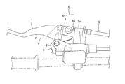
特許文献1に開示されている技術では、図32に示すように、ブレーキレバー1の回転軸2に対して揺動可能に配置された前輪リンク3と、ブレーキレバー1の回転軸2から離間した位置に設けられたリンク点に枢支されている後輪リンク4とが、主な構成要素とされている。
後輪リンク4の先端には、マスタシリンダ5のアンカ5aに固定された後輪ブレーキケーブル6のインナケーブル6aが固定され、前輪リンク3におけるマスタシリンダ5の押圧側端部には、他方のブレーキレバーの操作状態を伝達するための操作ケーブル(不図示)が連結されている。
ブレーキレバー1を握り込むように操作すると、後輪リンク4は回転軸2を中心として矢印Eの方向へ移動する。この動作により後輪リンク4は、ブレーキレバー1に対する相対的な回動が成され、前輪リンク3の一部を押圧する。後輪リンク4が前輪リンク3を押圧することにより、前輪リンク3は、回転軸2を基点として矢印Fの方向へ回動し、マスタシリンダ5を押圧する。
一方で、他方のブレーキレバーが操作された場合には、図示しないケーブルを介して前輪リンク3におけるマスタシリンダ押圧側端部がマスタシリンダ5側へ引き付けられる。これにより、前輪リンク3のみが回転軸2を中心として矢印Fの方向へ回動し、前輪側ブレーキのみが作動する。
このように、特許文献1に開示されているブレーキでは、前輪側ブレーキのみが作動される、あるいは前輪側ブレーキと後輪側ブレーキが連動して作動されるということを使い分けることを可能としている。
特許文献1に開示されているような前後連動ブレーキ機構では、その構造的な性質から、マスタシリンダを左側(操作側視点を基準として)に配置することが必須要件となる。しかし、後輪側ブレーキの操作がケーブルを用いて行われるブレーキシステムでは通常、左側にマスタシリンダが配置される構成が無い。このため、特許文献1に開示されているような前後連動ブレーキ機構が採用される場合には、マスタシリンダが専用品として用いられることとなる。仮に、特許文献1に開示されている前後連動ブレーキ機構が、マスタシリンダを右に配置して構成された場合には、右側のブレーキレバーが操作された際に後輪側ブレーキが作動する。このような挙動は、一般的な二輪車の構造的な常識からして誤動作を招く虞があり、危険を伴うこととなり、危険である。
このため、特許文献1に開示されている前後連動ブレーキ機構のような構成の場合、前後連動ブレーキ機構が採用されない廉価版の機種と、前後連動ブレーキ機構が採用される機種との両方を市場に提供するためには、左右2種類のマスタシリンダを在庫として抱える必要が生じてしまう。
また、特許文献1に開示されている技術では、連動ブレーキを構成するためにケーブル等を固定するブラケット部分がマスタシリンダに一体形成されており、マスタシリンダそのものを新たに設計する必要がある。
このような実状により、前後連動ブレーキ機構そのものが高価なものとなり、安全機構にも関わらず、その普及の妨げとなってしまっている。
そこで本発明では、操作側からの視点を基準として、マスタシリンダが右側に配置された場合であっても、連動ブレーキが成立することのできる前後連動ブレーキ機構を提供することを第1の課題とする。
また、本発明では、汎用品としてのマスタシリンダに対し、簡易な機構の付加により、前後連動ブレーキ機構が成立することのできる前後連動ブレーキ機構を提供することを第2の課題とする。
以上の観点から、本発明では、上記課題のうち、少なくとも1つを解決することのできる前後連動ブレーキ機構を提供することを目的とする。
本発明の上記目的は、下記構成により達成される。
(1) 前輪側ブレーキを作動するためのマスタシリンダと一方のブレーキレバーとの間にリンク機構が介在して構成される前後連動ブレーキ機構であって、
後輪ブレーキケーブルのインナケーブルである第1インナケーブルが接続され、固定軸と共に移動することにより前記第1インナケーブルを牽引する後輪リンクと、
他方のブレーキレバーまたはフットペダルのいずれか一方が操作されることによって牽引される伝達ケーブルのインナケーブルである第2インナケーブルが接続され、前記第2インナケーブルの牽引により回動されて前記後輪リンクの前記固定軸を移動するためのホルダと、を備えた前後連動ブレーキ機構。
(1) 前輪側ブレーキを作動するためのマスタシリンダと一方のブレーキレバーとの間にリンク機構が介在して構成される前後連動ブレーキ機構であって、
後輪ブレーキケーブルのインナケーブルである第1インナケーブルが接続され、固定軸と共に移動することにより前記第1インナケーブルを牽引する後輪リンクと、
他方のブレーキレバーまたはフットペダルのいずれか一方が操作されることによって牽引される伝達ケーブルのインナケーブルである第2インナケーブルが接続され、前記第2インナケーブルの牽引により回動されて前記後輪リンクの前記固定軸を移動するためのホルダと、を備えた前後連動ブレーキ機構。
(2) 前記後輪ブレーキケーブルのアウタケーブルである第1アウタケーブルと、前記伝達ケーブルのアウタケーブルである第2アウタケーブルとを支持することにより、前記第1インナケーブルまたは前記第2インナケーブルの牽引に伴うケーブル全体の移動を防ぐケーブルアンカを備え、前記マスタシリンダと別体として構成されたブラケットが設けられた上記(1)の構成の前後連動ブレーキ機構。
上記(1)又は(2)のような構成とすることによれば、鋳造品であるマスタシリンダを専用品とする必要性が無い。このため、前後連動ブレーキ機構が搭載されない廉価版のブレーキ機構と共通のマスタシリンダを採用しつつ、附帯部品の組付けを行うだけで前後連動ブレーキ機構を付加することができる。よって、簡易かつ安価に前後連動ブレーキ機構を付加することができる。
(3) 前記第1アウタケーブルのアンカ位置と前記第1インナケーブルの連結位置、並びに前記第2アウタケーブルのアンカ位置と前記第2インナケーブルの連結位置が共に、前記マスタシリンダと、前記後輪リンクと、前記ホルダと、前記ブラケットと、前記一方のブレーキレバーとが組み付けられた状態で外周に露出する位置に配置された上記(2)の構成の前後連動ブレーキ機構。
上記(3)のような構成とすることによれば、前輪リンク、後輪リンク、およびホルダがマスタシリンダに組付けられた後に、ケーブル類を引き回すことが可能となる。
上記(3)のような構成とすることによれば、前輪リンク、後輪リンク、およびホルダがマスタシリンダに組付けられた後に、ケーブル類を引き回すことが可能となる。
(4) 前記第1インナケーブルと前記後輪リンクとの連結部が、前記一方のブレーキレバーの操作平面と同一平面上に配置され、
前記第2インナケーブルと前記ホルダとの連結部が前記操作平面上から外されると共に、前記一方のブレーキレバーの操作回転軸となる連結ボルトを挿通するための軸孔が、前記第2インナケーブルと前記ホルダとの連結部が配置された板片に設けられた上記(1)~(3)のいずれか1つの構成の前後連動ブレーキ機構。
上記(4)のような構成とすることによれば、前後連動ブレーキ機構の平面視構成を小さくすることができる。
前記第2インナケーブルと前記ホルダとの連結部が前記操作平面上から外されると共に、前記一方のブレーキレバーの操作回転軸となる連結ボルトを挿通するための軸孔が、前記第2インナケーブルと前記ホルダとの連結部が配置された板片に設けられた上記(1)~(3)のいずれか1つの構成の前後連動ブレーキ機構。
上記(4)のような構成とすることによれば、前後連動ブレーキ機構の平面視構成を小さくすることができる。
(5) 前記第1インナケーブルと前記後輪リンクの連結部、並びに前記第2インナケーブルと前記ホルダとの連結部の双方が、前記一方のブレーキレバーの操作平面上から外され、
2つの前記連結部が、前記マスタシリンダの下部側に配置された上記(1)~(3)のいずれか1つの構成の前後連動ブレーキ機構。
上記(5)のような構成によっても、前後連動ブレーキ機構の平面視構成を小さくすることができる。
2つの前記連結部が、前記マスタシリンダの下部側に配置された上記(1)~(3)のいずれか1つの構成の前後連動ブレーキ機構。
上記(5)のような構成によっても、前後連動ブレーキ機構の平面視構成を小さくすることができる。
(6) 前記後輪リンクが、前記固定軸を基点として前記固定軸の移動方向と反対側へ回動することを防止するための回動防止機構が、前記後輪リンクと前記ホルダとの間に設けられた上記(1)~(5)のいずれか1つの構成の前後連動ブレーキ機構。
上記(6)のような構成を有する前後連動ブレーキ機構によれば、マスタシリンダの油圧が失陥した場合であっても、後輪側ブレーキが操作される際に、ストローク変動を少なくすることができる。
上記(6)のような構成を有する前後連動ブレーキ機構によれば、マスタシリンダの油圧が失陥した場合であっても、後輪側ブレーキが操作される際に、ストローク変動を少なくすることができる。
(7) 前記後輪リンクと接触するカム部が設けられ、前記一方のブレーキレバーが操作されることにより、または前記後輪リンクにより前記カム部が押圧されることにより回動して、前記マスタシリンダのピストンを押圧する前輪リンクを備え、
前記後輪リンクは、非制動状態において、前記カム部に接触すると共に前記回動防止機構が機能している状態に位置する上記(6)の構成の前後連動ブレーキ機構。
上記(7)のような特徴を有することによれば、後輪リンクは、正常状態であっても、マスタシリンダの油圧が失陥した異常状態であっても、制動時におけるレバー操作、あるいはペダル操作において、ストロークの変動を少なく抑えて後輪側ブレーキを作動させることができる。
前記後輪リンクは、非制動状態において、前記カム部に接触すると共に前記回動防止機構が機能している状態に位置する上記(6)の構成の前後連動ブレーキ機構。
上記(7)のような特徴を有することによれば、後輪リンクは、正常状態であっても、マスタシリンダの油圧が失陥した異常状態であっても、制動時におけるレバー操作、あるいはペダル操作において、ストロークの変動を少なく抑えて後輪側ブレーキを作動させることができる。
(8) 前記回動防止機構は、前記後輪リンクと前記ホルダの双方に設けられた突起部である上記(6)又は(7)の構成の前後連動ブレーキ機構。
上記(8)のような特徴を有することによれば、可動するリンク同士に突起部を設け、これを回動防止機構とすることで、後輪リンクと前輪リンクのカム部とが接触した状態で、突起部同士が接触するという構成を採ることが可能となる。
上記(8)のような特徴を有することによれば、可動するリンク同士に突起部を設け、これを回動防止機構とすることで、後輪リンクと前輪リンクのカム部とが接触した状態で、突起部同士が接触するという構成を採ることが可能となる。
上記(1)~(8)のような構成を有する前後連動ブレーキ機構によれば、操作側からの視点を基準として、マスタシリンダが右側に配置された場合であっても、前後連動ブレーキ機構を成立させることができる。
以下、本発明の前後連動ブレーキ機構(以下、単に連動ブレーキ機構と称する)に係る実施の形態について、図面を参照しつつ詳細に説明する。なお、本発明に係るブレーキ機構は、図4に示すように、従来と同様、マスタシリンダ12を介した油圧機構により前輪側ブレーキ104が作動され、後輪側のブレーキ作動機構に連結されたケーブルを牽引することで後輪側ブレーキ106が作動されるものを基本として構成されている。以下、図1~図8を参照して、第1の実施形態に係る連動ブレーキ機構の基本形態について説明する。
図4に示すように、本第1の実施形態は二輪車(主に自動二輪車)を対象としたものであり、ハンドル100における一対のグリップ部102a,102bには、それぞれ一方のブレーキレバー14と他方のブレーキレバー16が備えられている。なお、ここでいう一方のブレーキレバー14と他方のブレーキレバー16とは、左右のグリップ部102a,102bのいずれかに取り付けられていることを限定するものでは無いが、本第1の実施形態においては、詳細が後述されるマスタシリンダ12に組付けられるブレーキレバー、すなわち右側のグリップ部102bに取り付けられているブレーキレバーを一方のブレーキレバー14と称している。
図1~図3に示すように、一方のブレーキレバー14が配置されるグリップ部102b側には、ブレーキレバー(一方のブレーキレバー14)の他、マスタシリンダ12と、ブラケット18、ホルダ30、前輪リンク20、後輪リンク22とが配置されている。
図7に示すように、マスタシリンダ12は、前輪側ブレーキ104を作動するための油圧機構の動作源である。マスタシリンダ12は、マスタシリンダボディ12aと、ピストン12bと、スプリング12cと、取付部12dと、レバー組付部12eとが基本として構成されている。マスタシリンダボディ12aは、フルードを圧送するためのシリンダを構成する要素であり、図示しないキャリパ側ピストンの押し出しによって不足するフルードを補うためのフルードタンク12fが一体形成されている(図5参照)。
ピストン12bは、マスタシリンダボディ12aに形成されたシリンダ内に貯留されたフルードを圧送するための押圧要素である。ピストン12bは、シリンダ内に配置され、外部からの押圧を受けることにより、シリンダ内部へ押し込まれ、シリンダ内部に貯留されているフルードをキャリパへと圧送する。
スプリング12cは、シリンダ内へ押し込まれたピストン12bを初期位置へ押し戻すための要素である。このためスプリング12cは、シリンダ内部に配置され、ピストン12bからの押圧に対する反力を発生する。なお、ピストン12bの押し戻し時に、シリンダの容積的に不足分となるフルードが、フルードタンク12fから補充される。
取付部12dは、マスタシリンダ12をハンドル100のグリップ部102b近傍に組み付けるための要素である。図5に示す円弧部がハンドル100の組付部に当接され、図示しないホルダを介してハンドル100を挟み込んで固定することで、組付けが完了する。
図5に示すように、レバー組付部12eは、一方のブレーキレバー14を回動可能に支持する要素である。レバー組付部12eは、一方のブレーキレバー14の回動方向、すなわち操作平面に沿ってスリットが形成されており、一方のブレーキレバー14における組付部14aが介入される。
図6の(B)に示すように、一方のブレーキレバー14は、操作部14bと組付部14aとより構成されている。操作部14bは、マスタシリンダ12におけるレバー組付部12eに組付けられた組付部14aの回転中心を基点として回動するレバーである。組付部14aには、連結孔14cと、操作平面に沿った方向のスリット14eが設けられている。連結孔14cは、マスタシリンダ12におけるレバー組付部12eとの連結を図るための孔であり、組付部14aがレバー組付部12eのスリットに介入した状態で連結ボルト14fが挿通されることで回動自在な固定が成される。なお、連結ボルト14fと組付部14aとの間には、スリーブ14gが配置される(図2参照)。これにより、一方のブレーキレバー14の回動により連結ボルト14fの締め付けが緩むことを避けることができる。
ブラケット18は、主に、詳細が後述される後輪ブレーキケーブル24のアウタケーブル(第1アウタケーブル24a)と、伝達ケーブル26のアウタケーブル(第2アウタケーブル26a)を支持するためのケーブルアンカ18a,18bを備えるための要素である。本第1の実施形態では、ケーブルアンカ18aが一方のブレーキレバーの操作平面と同一平面上に配置されている。一方、ケーブルアンカ18bは、ケーブルアンカ18aよりも下側、すなわち一方のブレーキレバーの操作平面よりも下側に位置するように配置されている。ケーブルアンカ18a,18bがこのような配置形態とされることにより、複数のケーブルが引き回されるマスタシリンダ12の組付け部周辺の構成を小型化することが可能となる。
また、図5に示すように、ブラケット18には、詳細が後述される作動スプリング28を係止するための係止部18cが設けられている。係止部18cは、単なるピンを形成するようにしても良いが、ピポットボルトのように、側面に凹凸が設けられたピンを配置することで、作動スプリング28の脱落を防ぐようにすることが望ましい。
本第1の実施形態では、このような構成とされるブラケット18が、マスタシリンダ12におけるレバー組付部12eの一部を利用して固定されている。具体的には、レバー組付部12eとの対向面に、レバー組付部12eの下面に嵌る凹凸形状が形成されることで、ブラケット18の回り止めが図られる。また、一方のブレーキレバー14が軸支される連結ボルト14fの先端に共締めされることで、ブラケット18の脱落防止が図られるというものである。
ホルダ30にはリンク孔30b、連結孔30aが形成され、マスタシリンダ12に対して、ブラケット18、一方のブレーキレバー14、前輪リンク20と共に、連結ボルト14fにより共締めされる。なお、ホルダ30は、一方のブレーキレバー14における組付部14aのスリット14e間に収められる。本第1の実施形態では、ホルダ30がスリット14eの間に収められる際に、詳細が後述される前輪リンク20および後輪リンク22により、当該ホルダ30が挟み込まれるような配置形態が採られる(例えば図6(A)及び図6(B)参照)。このような構成とすることで、後輪リンク22は、ホルダ30の動作に連動して移動する。
また、ホルダ30には、連結孔30aを基点としてリンク孔30bと反対側に、伝達ケーブル26における第2インナケーブル26bを連結するケーブル連結部30cを配置するための連結片30dが設けられる。そして、この連結片30dを介して前輪リンク20よりも下側に、ケーブル連結部30cが設けられる構成とされている。また、ケーブル連結部30cには、連結ボルト14fを挿通するための軸孔30eが形成されている。このような構成のリンク機構とすることで、第2インナケーブル26bが牽引されることにより、ホルダ30が回動し、後輪リンク22の移動が成され、後輪側ブレーキ106が作動する。さらに、伝達ケーブル26の引き回し経路、第2アウタケーブル26aのアンカ位置、および第2インナケーブル26bの連結位置が、いずれもマスタシリンダ12に対して前輪リンク20と、後輪リンク22と、ブラケット18と、ホルダ30と、一方のブレーキレバー14とが組み付けられた状態で、外部から視認およびアクセスすることが可能となる。このため、マスタシリンダ12に対して前輪リンク20と、後輪リンク22と、ブラケット18と、ホルダ30と、一方のブレーキレバー14とが組み付けられた状態で、第2インナケーブル26bを着脱することが可能となる。
前輪リンク20は、マスタシリンダ12におけるピストン12bを押圧するための要素である。前輪リンク20は、一方のブレーキレバー14における組付部14aのスリット14eに配置され、連結ボルト14fを介して回動自在に固定される。このため、前輪リンク20には連結孔20aが形成されている。連結孔20aを基点として、組付状態においてマスタシリンダ12におけるピストン12b配置側に位置する部位には、ピストン12bを押圧するための押圧部20bが形成されている。
また、図6(A)に示すように、本第1の実施形態における前輪リンク20には、力伝達部20fが形成されている。力伝達部20fは、一方のブレーキレバー14の操作に伴う回動を前輪リンク20に伝達する部位であり、一方のブレーキレバー14の握り込み側側面の一部に接触するように構成されている。このような構成とすることにより、一方のブレーキレバー14が操作されることにより前輪リンク20が回動し、押圧部20bがマスタシリンダ12のピストン12bを押圧し、前輪側ブレーキ104が作動する。
また、後輪リンク22は、第1インナケーブル24bを連結するための要素である。後輪リンク22は、一方のブレーキレバー14における組付部14aのスリット14eに配置され、ホルダ30に形成されたリンク孔30bに対してリンクピン(固定軸)14h(図7参照)を介して回動自在に固定される。このため、後輪リンク22には、リンク孔22aが形成されている。そして、連結孔20aを基点として、組付状態においてマスタシリンダ12と最も離れた位置には、第1インナケーブル24bを連結するための連結部であるケーブル連結部22bが形成されている。そして、リンク孔22aを基点としてケーブル連結部22bと反対側には、上述した前輪リンク20におけるカム部20dに接触するカム部22dと、作動スプリング28を係止するための係止ピン22cが形成されている。
このような構成によれば、後輪ブレーキケーブル24の引き回し経路、第1アウタケーブル24aのアンカ位置と第1インナケーブル24bの連結位置が、いずれもマスタシリンダ12に対して前輪リンク20と、後輪リンク22と、ブラケット18と、ホルダ30と、一方のブレーキレバー14とが組み付けられた状態で、外部から視認、およびアクセスすることが可能となる。このため、マスタシリンダ12に対して前輪リンク20と、後輪リンク22と、ブラケット18と、ホルダ30と、一方のブレーキレバー14とが組み付けられた状態で、第1インナケーブル24bを着脱することが可能となる。
次に図8を参照して、本第1の実施形態に係る連動ブレーキ機構における動作について説明する。まず、図8の(A)は、ブレーキ操作が行われていない状態である。次に、図8の(B)は、一方のブレーキレバー14が操作された状態を示す。一方のブレーキレバー14を握り込むように操作すると、前輪リンク20の力伝達部20fが一方のブレーキレバー14によって押圧され、連結孔20aを基点として前輪リンク20が矢印Aの方向へ回動する。これにより、押圧部20bがマスタシリンダ12のピストン12bを押圧し、前輪側ブレーキ104が作動する。
次に、他方のブレーキレバー16を握り込むように操作すると、伝達ケーブル26(図3参照)における第2インナケーブル26bが牽引される。第2インナケーブル26bは、ホルダ30における連結部であるケーブル連結部30cに連結されているため、第2インナケーブル26bの牽引に伴いホルダ30は図8の(C)で示すように、連結孔30aを基点として矢印Aの方向へ回動する。ホルダ30の回動に伴い後輪リンク22を固定しているリンク孔22aも連結孔30aを基点として矢印Aの方向へ移動し、第1インナケーブル24bが牽引され、後輪側ブレーキ106が作動する。この時、後輪リンク22は、作動スプリング28の張力(引付力)と、前輪リンク20を介したピストン12bの反力により、矢印Dの方向へ倒れ込むことが抑制されている。
後輪側ブレーキ106が作動した後、さらに他方のブレーキレバー16を握り込むように操作すると、ホルダ30の回動に伴い、後輪リンク22も連結孔30aを基点として矢印Aの方向へとさらに移動する。後輪リンク22の移動に伴いリンク孔22aの位置が変化すると、作動スプリング28の引付力とピストン12bの反力の合力よりも第1インナケーブル24bの反力(牽引力に対する反力)が強くなり、リンク孔22aを基点として、後輪リンク22が矢印Dの方向へと回動する。これにより、図8の(D)に示すように、後輪リンク22のカム部22dが前輪リンク20の力伝達部20fを押圧し、連結孔20aを基点として前輪リンク20が矢印Aの方向へ回動される。前輪リンク20が矢印Aの方向へ回動すると、押圧部20bがマスタシリンダ12のピストン12bを押圧する。これにより、前輪側ブレーキ104が作動し、前輪側ブレーキ104及び後輪側ブレーキ106の双方が他方のブレーキレバー16の操作に連動して作動する。
本第1の実施形態に係る連動ブレーキ機構10によれば、図9の(A)及び(B)に示すように、通常の前輪側ブレーキ機構として使用しているマスタシリンダ12に対して、ブラケット18と、前輪リンク20と、後輪リンク22と、一方のブレーキレバー14と、作動スプリング28と、ホルダ30とが付加されると共に、後輪ブレーキケーブル24と伝達ケーブル26を引き回すだけで、その機能を発揮することができる。このため、従来のようにマスタシリンダを専用設計とする必要が無く、安価に提供することができる。また、使用するマスタシリンダ12を通常のブレーキ機構と同一とすることができるため、既存の生産ライン上にて、オプションとして付加部品を追加するだけで対応することができる。さらに、本第1の実施形態の機構によれば、マスタシリンダ12が配置された側のブレーキレバーが前輪側ブレーキ104として機能することができる。
また、本第1の実施形態に係る連動ブレーキ機構10によれば、伝達ケーブル26との連結部が、マスタシリンダ12の中心を含む一方のブレーキレバー14の操作平面から外された場合であっても、伝達ケーブル26を構成する第2インナケーブル26bが連結されている板片により形成されたリンクであるホルダ30は、操作平面上に配置された連結孔30aと、ケーブル連結部30cに配置された軸孔30eとの二点によって連結ボルト14fが挿通され、同一軸で回動可能に保持される。このため、ケーブルの牽引に伴う回転部のコジリ力が緩和され、変形や摩耗を抑制することができる。また、このような構成は、1枚の板片により形成することができるため、構造そのものを安価なものとすることができる。
また、本第1の実施形態に係る連動ブレーキ機構10は、左手側ハンドルにクラッチレバー(不図示)を配置したタイプの二輪車にも、適用することができる。この場合には、他方のブレーキレバー16に替えて、図示しないフットペダルに対して伝達ケーブル26を接続する構成とすれば良い。このような構成よれば、当該フットペダルの踏み込み操作により、伝達ケーブル26における第2インナケーブル26dの牽引が行われ、本第1の実施形態に係る連動ブレーキ機構10におけるホルダ30が回動され、後輪側ブレーキ106および前輪側ブレーキ104の双方が作動することができる。
次に、図10~図12を参照して本第1の実施形態に係る連動ブレーキ機構の応用形態について説明する。本応用形態に係る連動ブレーキ機構の殆どの構成は、上述した第1の実施形態に係る連動ブレーキ機構10と同様である。相違点としては、ホルダ30の構成を挙げることができる。
上述した第1の実施形態では、ホルダ30の本体部分から連結片にかけての構造が1枚の板片により構成されていた。そして、このホルダ30が2つ折りにした板片により構成されている前輪リンク20と後輪リンク22の間、すなわち、上側の板片と下側の板片の間に配置される構成とされていた。これに対し本応用形態では、ホルダ30が2つ折りにした板片により構成され、このホルダ30における上側の板片と下側の板片の間に、前輪リンク20と後輪リンク22が配置される構成とされている。
なお、その他の構成については、上述した第1の実施形態に係る連動ブレーキ機構10と同様である。そして、連動ブレーキ機構10の構成がこの応用形態とされた場合であっても、上述し第1形態に係る連動ブレーキ機構10と同様な作用、効果を発揮することができる。
次に、図13~図20を参照して、本発明の連動ブレーキ機構に係る第2の実施形態について説明する。本第2の実施形態に係る連動ブレーキ機構10aの殆どの構成は、上述した第1の実施形態に係る連動ブレーキ機構10と同様である。相違点としては、ブラケット18やホルダ30の構成、およびストッパ22e,32gの有無等を挙げることができる。よって、その機能を同一とする箇所については、図面に同一符号を付して、その詳細な説明を省略する。
図13及び図14に示すように、本第2の実施形態に係る連動ブレーキ機構10aにおいても、一方のブレーキレバー14が配置されるグリップ部102b側には、ブレーキレバー(一方のブレーキレバー14)の他、マスタシリンダ12と、ブラケット18と、前輪リンク20と、後輪リンク22と、ホルダ32とが配置されている。
また、本第2の実施形態では図15に示すように、ブラケット18が、マスタシリンダ12の下面側に固定される構成は、上述した第1の実施形態と同様とされているが、ケーブルアンカ18aの配置形態が異なっている。具体的には、第1アウタケーブル24aを支持するケーブルアンカ18aと、第2アウタケーブル26aを支持するためのケーブルアンカ18bとが双方共、マスタシリンダ12の下面側に配置される構成とされている。即ち、第1インナケーブル24bと後輪リンク22の連結部であるケーブル連結部22b、並びに第2インナケーブル26bとホルダ32との連結部であるケーブル連結部32cの双方が、一方のブレーキレバー14の操作平面上から外され、2つのケーブル連結部22b,32cが、マスタシリンダ12の下部側に配置されている。このような構成とすることで、マスタシリンダ12を平面視した際のシリンダ周りの平面積を減らすことができる。よって、マスタシリンダ12周りの小型化を図ることができ、前後連動ブレーキ機構の平面視構成を小さくすることができる。
図16~図18に示すように、本第2の実施形態に係る前輪リンク20は、押圧片20gとリンク片20h、および連結片20iとによって構成されている。押圧片20gは、ピストン12bを押圧するための押圧部20bと、前輪リンク20を回動自在に固定するための連結孔20aとが設けられた板片である。押圧片20gは、組付け状態では、一方のブレーキレバー14における組付部14aのスリット14eに配置される。これに対しリンク片20hは、組付状態で組付部14aの下面に配置される板片であって、連結孔20aとカム部20dを有する。そして、連結片20iは、前述した押圧片20gとリンク片20hを連結するための板片である。本第2の実施形態では、一方のブレーキレバー14における操作部14b側に、連結片20iが、操作部14bの操作方向側面に接触するように設けられる。よって、前輪リンク20における連結片20iは、前輪リンク20における一方のブレーキレバー14からの力伝達部20fを構成する。
このような構成の前輪リンク20は、押圧片20gとリンク片20hが、一方のブレーキレバー14の一部を挟み込むようにして配置され、連結孔20aを介して連結ボルト14fで固定される。また、このような構成の前輪リンク20を平面視すると、図19に示すように、連結孔20aを基点として、押圧部20bとカム部20dがそれぞれ反対方向に位置するように配置されている。また、力伝達部20fは、当該力伝達部20fを力点とした場合に、連結孔20aが支点、押圧部20bが作用点となる関係を持つように配置される。
このような構成とすることにより、前輪リンク20は、力伝達部20fおよびカム部20dのいずれに対する力の入力によっても、その方向が矢印A(図16参照)に沿った方向であれば、連結孔20aを基点として矢印Aの方向へ回動し、押圧部20bがピストン12bを押圧する。
なお、本第2の実施形態に係る前輪リンク20には、連結片20iに、作動スプリング28を係止するための係止孔20jが形成されている(図17参照)。
本第2の実施形態に係る後輪リンク22は、詳細が後述されるホルダ32における一方のリンク片32aと他方のリンク片32bの間に介在される。また、本第2の実施形態に係る後輪リンク22には、後輪リンク22の初期位置を定めると共に、後輪リンク22が矢印Dの方向へと回動することを防止する突起部であるストッパ22e(回動防止機構)が形成されている。さらに、本第2の実施形態に係る後輪リンク22では、上述した第1の実施形態における後輪リンク22の係止ピン22cに替え、作動スプリング28を係止するための爪22fが形成されている。爪22fは、リンク孔22aを基点としてストッパ22eと反対側に配置されている。
図16~図18に示すように、本第2の実施形態に係るホルダ32は、一方のリンク片32aと他方のリンク片32b、および連結片32eとより構成される。一方のリンク片32aと他方のリンク片32bは、それぞれ、前輪リンク20におけるリンク片20hと後輪リンク22を挟み込むように配置することが可能なように、間隙をあけて配置され、連結片32eによって位置決めされている。
ホルダ32には、連結孔32cと、リンク孔32dと、ケーブル連結部32fとが設けられている。連結孔32cは、前輪リンク20や一方のブレーキレバー14と共に連結ボルト14fによってマスタシリンダ12に共締めされる孔であり、ホルダ32は、この連結孔32cを基点として回動することが可能とされている。リンク孔32dは、リンクピン14hを介して、後輪リンク22を回動可能に固定するための孔である。そして、ケーブル連結部32fは、第2インナケーブル26bを連結するための連結部であり、連結孔32cを基点として、リンク孔32dと反対側となる位置に配置されている。
このような構成および配置形態とすることで、ホルダ32は、第1の実施形態に係る連動ブレーキ機構10と同様に、第2インナケーブル26bが牽引されることにより、連結孔32cを基点として矢印Aの方向へ回動する。これにより、リンクピン14hを介して固定された後輪リンク22が矢印Aの方向へ移動され、第1インナケーブル24bを牽引することが可能となる。
また、図19に示すように、第2の実施形態に係るホルダ32は、連結片32eの少なくとも一部が第1インナケーブル24bの牽引方向と反対側に配置され、後輪リンク22におけるストッパ22eと当接する突起部であるストッパ32g(回動防止機構)を構成している。このような構成とすることで、後輪リンク22は、リンクピン14hを基点として矢印Aの方向への回動が自由とされる一方で、矢印Dの方向への回動は、ストッパ22eとストッパ32gが当接することで妨げられる(図16参照)。
次に、図20を参照して、本第2の実施形態に係る連動ブレーキ機構における動作について説明する。まず、図20の(A)は、ブレーキ操作が行われていない状態である。次に、図20の(B)は、一方のブレーキレバー14が操作された状態を示す。一方のブレーキレバー14が握り込むように操作されると、前輪リンク20の力伝達部20fが一方のブレーキレバー14によって押圧される。これにより、前輪リンク20は、連結孔20aを基点として矢印Aの方向へ回動する。この作用により、押圧部20bがマスタシリンダ12のピストン12bを押圧し、前輪側ブレーキ104が作動する。
次に、他方のブレーキレバー16が握り込むように操作されると、伝達ケーブル26における第2インナケーブル26bが牽引される。第2インナケーブル26bは、ホルダ32におけるケーブル連結部32fに連結されているため、第2インナケーブル26bの牽引に伴いホルダ32は、図20の(C)で示すように、連結孔32cを基点として矢印Aの方向へ回動する。ホルダ32の回動に伴い後輪リンク22を固定しているリンク孔22aも移動する。
ここで、後輪リンク22のカム部22dは、前輪リンク20のカム部20dと接触しており、かつ後輪リンク22は、作動スプリング28(図20には、不図示:図3参照)により、矢印Aの方向へ回動する力が付与されている。このため、前輪リンク20の回動を止めているマスタシリンダ12のピストン12bによる反力と、作動スプリング28による引付力により、後輪リンク22はカム部22dとカム部20dの接触点を基点として矢印Aの方向へ回動する。この動作により、第1インナケーブル24bが牽引され、後輪側ブレーキ106が前輪側ブレーキ104よりも先に作動する。
後輪側ブレーキ106が作動した後、さらに他方のブレーキレバー16を握り込むように操作すると、第2インナケーブル26bの反力(牽引力に対する反力)が、ピストン12bによる反力と作動スプリング28による引付力の合力を超える。このような状態に達すると、後輪リンク22は、図20(D)に示すように、カム部22dが前輪リンク20のカム部20dを押圧することにより移動され、連結孔20aを基点として前輪リンク20が矢印Aの方向へ回動される。これにより、前輪側ブレーキ104が作動し、前輪側ブレーキ104、後輪側ブレーキ106の双方が他方のブレーキレバー16の操作に連動して作動する。
上記のような構成の連動ブレーキ機構10aでは、その作動原理に関し、前輪リンク20の回動を制限するピストン12bの反力と、作動スプリング28の引付力が作用することで、後輪リンク22が矢印Aの方向へ回動し、後輪側ブレーキ106が作動する旨記載した。このような機構の場合、ピストン12bの反力を生じさせるマスタシリンダ12の油圧が失陥すると、前輪リンク20の回動が自由となる。
本第2の実施形態に係る連動ブレーキ機構10aでは、ピストン12bの反力と、作動スプリング28の引付力(張力)の合力により、第1インナケーブル24bの初動反力よりも大きな力が生じ、後輪リンク22がリンク孔22aの移動に伴い、カム部22dとカム部20dの接点を基点として矢印Aの方向へ回動された。このため、マスタシリンダ12の油圧が失陥し、作動スプリング28の引付力のみとなった場合には、第1インナケーブル24bの初動反力が作動スプリング28の引付力よりも大きくなる。こうした場合、ホルダ32の回動に伴って後輪リンク22が矢印Aの方向へ移動すると、後輪リンク22には、第1インナケーブル24bの初動反力により、矢印Dの方向へ回動させようとする力の割合が大きくなる。
ここで本第2の実施形態に係る連動ブレーキ機構10aでは、ホルダ32と後輪リンク22の双方に、後輪リンク22が矢印Dの方向、すなわち第1インナケーブル24bの牽引方向と反対方向へ回動することを防止するためのストッパ32g,22eが設けられている。このため、後輪リンク22は、初期位置を維持したまま、ホルダ32の回動に合わせてリンクピン14hと共に矢印Aの方向へ移動し、第1インナケーブル24bの牽引が成される。
よって、本第2の実施形態に係る連動ブレーキ機構10aでは、マスタシリンダ12の油圧が失陥した場合であっても、他方のブレーキレバー16のストロークの増加が少なく抑えられて後輪側ブレーキ106は作動することができる。
また、本第2の実施形態に係る連動ブレーキ機構10aも、上述した第1の実施形態に係る連動ブレーキ機構10と同様に、通常の前輪側ブレーキ機構として使用しているマスタシリンダ12に対して、ブラケット18と、前輪リンク20と、後輪リンク22と、ホルダ32と、一方のブレーキレバー14と、作動スプリング28とが付加されると共に、後輪ブレーキケーブル24と伝達ケーブル26が引き回されるだけでその機能を発揮することができる。
なお、上記第2の実施形態では、後輪リンク22の回転を抑制するためのストッパは、ホルダ32と後輪リンク22の双方に設ける構成とされている。しかしながら、後輪リンク22の初期位置を定めることができ、第1インナケーブル24bの牽引方向と反対側へ後輪リンク22が回転することを防止することができる構成であれば、ストッパは、後輪リンク22とホルダ32のいずれか一方に設けられていれば良い。また、本第2の実施形態に係るストッパは、第1インナケーブル24bの牽引方向と反対側へ後輪リンク22が回転することを防止することができれば良く、突起やピンのような簡易な構成とすることができる。このため、上記第1の実施形態に係る連動ブレーキ機構10のような構成であっても適用することができる。具体的な例としては、係止ピン22cの位置が変更され、初期位置においてホルダ30と接触するような構成とすれば良い。
また、本第2の実施形態に係る連動ブレーキ機構10aは、左手側ハンドルにクラッチレバー(不図示)を配置したタイプの二輪車にも、適用することができる。この場合には、他方のブレーキレバー16に替えて、図示しないフットペダルに対して伝達ケーブル26が接続される構成とすれば良い。このような構成とすることによれば、当該フットペダルの踏み込み操作により、伝達ケーブル26における第2インナケーブル26dの牽引が行われ、本第2の実施形態に係る連動ブレーキ機構10aにおけるホルダ32が回動され、後輪側ブレーキ106および前輪側ブレーキ104の双方が作動される。
次に、本第2の実施形態に係る連動ブレーキ機構に関する第1及び第2の応用形態について、図21~図31を参照して説明する。以下に示す第1及び第2の応用形態の連動ブレーキ機構は、前輪リンク、後輪リンク、ホルダ等の付加的要素を予め別工程で組付けた上で、一纏りのユニットとして、マスタシリンダに組付けることを可能としている。なお、その他の構成については、上述した第2の実施形態に係る連動ブレーキ機構10aと殆ど同じである。よって、その構成、作用を同一とする部分には、図面に同一符号を付して、その詳細な説明は省略する。
以下に示す第1及び第2の応用形態に係る連動ブレーキ機構は、いずれも、段付スリーブ34が、ホルダ32および前輪リンク20に貫通される構成としている点を特徴とする。
図21~図27に示した第1の応用形態に係る連動ブレーキ機構10aは、ブラケット18と、ホルダ32と、前輪リンク20と、後輪リンク22とが、1つのユニット(以下、リンクユニットと称す)として組み上げられ、これをマスタシリンダ12に組付けることが可能な構成とされている。具体的な構成は、次の通りである。
図22に示すように、本第1の応用形態では、ブラケット18の一部とホルダ32、前輪リンク20が重ねられ、ブラケット18の下部にホルダ32と前輪リンク20が配置される構成とされている。ブラケット18には、連結ボルト12fと段付スリーブ34を挿通するための貫通孔18dが設けられている(図26参照)。貫通孔18dには、段付スリーブ34のフランジ部34aが収容されるがザグリ18eが形成されている(図27参照)。前輪リンク20は、図25及び図26に示すように、ホルダ32の一方のリンク片32aと他方のリンク片32bの間に、リンク片20hが介入した状態となるように配置され、それぞれに形成された段孔18dおよび連結孔20a,32cを段付スリーブ34が貫くように配置されている。このような配置構成とすることで、段付スリーブ34は、フランジ部34aが段孔18dのザグリ18eに引っかかり、軸線方向下側へ抜け落ちる虞がない。
また、ホルダ32の一方のリンク片32aと他方のリンク片32bの間には、後輪リンク22も配置されている。後輪リンク22は、ホルダ32のリンク孔32dと後輪リンク22のリンク孔22aの双方にリンクピン14hが挿通されることで、リンクピン14hを基点として回動自在に保持されている。なお、リンクピン14hの固定方法は、特に限定するものでは無いが、図26に詳細を示すような割りピン15や、図示しないスナップリングのような簡易な固定方法であることが望ましい。
このように構成されたリンクユニットは、マスタシリンダ12への組付けに際し、マスタシリンダ12のレバー組付部12eの間に配置される一方のブレーキレバー14の組付部14aに形成されたスリット14eに、前輪リンク20の押圧片20gが介在される。このため、ホルダ32の一方のリンク片32aと、前輪リンク20の押圧片20gとの間には、レバー組付部12eの一部(下片)と、一方のブレーキレバー14における組付部14aの一部(下片)が配置される。よって、組付け状態では、段付スリーブ34は、フランジ部34aを含む軸線方向上側の端面がレバー組付部12eの下片によって押さえられ、軸線方向上側への抜け止めが図られる。
そして、前輪リンク20は、押圧片20gが組付部14aのスリット14eに介入されることにより、連結孔20aの軸線方向への移動が規制され、レバー組付部12eに保持される。このため、前輪リンク20のリンク片20hを挟み込んだホルダ32、およびレバー組付部12eとホルダ32との間に配置されるブラケット18も、段付スリーブ34の軸線方向への移動が規制される。
よって、レバー組付部12eと、組付部14aと、段付スリーブ34とに連結ボルト12fが挿通された後には、各構成要素は、軸線方向と交差する方向への移動が規制される。このため、連結ボルト12fの取り付け後には、連結ボルト12fを締付けるナット17が脱落した場合であっても、リンクユニットが脱落したり、ガタついたりするという虞が無く、高い安全性を確保することができる。
なお、その他の構成、作用、効果については、上述した第2の実施形態に係る連動ブレーキ機構10aと同様である。
次に、第2の応用形態について、図28~図31を参照して説明する。本第2の応用形態は、ブラケットがマスタシリンダに予め組み付けられている場合に好適な構成である。すなわち、ホルダ32と、前輪リンク20と、後輪リンク22とにより、一纏りのリンクユニットが構成されるものである。
具体的な構成は、上述した第1の応用形態と同様であり、段付スリーブ34がホルダ32と前輪リンク20に挿通され、前輪リンク20の押圧片20gが一方のブレーキレバー14におけるスリット14eに配置される。ここで、本第2の応用形態においては、リンクユニットにブラケット18が存在しない。このため、段付スリーブ34のフランジ部34aは、ホルダ32の一方のリンク片32a側に配置、当接される。その他の構成、作用、効果については、上述した第1の応用形態に係る連動ブレーキ機構10aと同様である。
ここで、上述した本発明に係る前後連動ブレーキ機構の実施形態の特徴をそれぞれ以下に簡潔に纏めて列記する。
[1] 前輪側ブレーキ104を作動するためのマスタシリンダ12と一方のブレーキレバー14との間にリンク機構が介在して構成される前後連動ブレーキ機構10であって、
後輪ブレーキケーブル24のインナケーブルである第1インナケーブル24bが接続され、固定軸(リンクピン)14hと共に移動することにより前記第1インナケーブル24bを牽引する後輪リンク22と、
他方のブレーキレバー16またはフットペダルのいずれか一方が操作されることによって牽引される伝達ケーブル26のインナケーブルである第2インナケーブル26bが接続され、前記第2インナケーブル26bの牽引により回動されて前記後輪リンク22の前記固定軸(リンクピン)14hを移動するためのホルダ30と、を備えた前後連動ブレーキ機構10。
[2] 前記後輪ブレーキケーブル24のアウタケーブルである第1アウタケーブル24aと、前記伝達ケーブル26のアウタケーブルである第2アウタケーブル26aとを支持することにより、前記第1インナケーブル24bまたは前記第2インナケーブル26bの牽引に伴うケーブル全体の移動を防ぐケーブルアンカ18a,18bを備え、前記マスタシリンダ12と別体として構成されたブラケット18が設けられた上記[1]に記載の前後連動ブレーキ機構10。
[3] 前記第1アウタケーブル24aのアンカ位置と前記第1インナケーブル24bの連結位置、並びに前記第2アウタケーブル26aのアンカ位置と前記第2インナケーブル26bの連結位置が共に、前記マスタシリンダ12と、前記後輪リンク22と、前記ホルダ30と、前記ブラケット18と、前記一方のブレーキレバー14とが組み付けられた状態で外周に露出する位置に配置された上記[2]に記載の前後連動ブレーキ機構10。
[4] 前記第1インナケーブル24bと前記後輪リンク22との連結部(ケーブル連結部)22bが、前記一方のブレーキレバー14の操作平面と同一平面上に配置され、
前記第2インナケーブル26bと前記ホルダ32との連結部(ケーブル連結部)30cが前記操作平面上から外されると共に、前記一方のブレーキレバー14の操作回転軸となる連結ボルト14fを挿通するための軸孔30eが、前記第2インナケーブル26bと前記ホルダ30との連結部(ケーブル連結部)30cが配置された板片に設けられた上記[1]~[3]のいずれか1つに記載の前後連動ブレーキ機構10。
[5] 前記第1インナケーブル24bと前記後輪リンク22の連結部(ケーブル連結部)22b、並びに前記第2インナケーブル26bと前記ホルダ32との連結部(ケーブル連結部)30cの双方が、前記一方のブレーキレバー14の操作平面上から外され、
2つの前記連結部(ケーブル連結部)22b,32fが、前記マスタシリンダ12の下部側に配置された上記[1]~[3]のいずれか1つに記載の前後連動ブレーキ機構10a。
[6] 前記後輪リンク22が、前記固定軸(リンクピン)14hを基点として前記固定軸(リンクピン)14hの移動方向と反対側へ回動することを防止するための回動防止機構(ストッパ)22e,32gが、前記後輪リンク22と前記ホルダ32との間に設けられた上記[1]~[3]のいずれか1つに記載の前後連動ブレーキ機構。
[7] 前記後輪リンク22と接触するカム部20dが設けられ、前記一方のブレーキレバー14が操作されることにより、または前記後輪リンク22により前記カム部20dが押圧されることにより回動して、前記マスタシリンダ12のピストン12bを押圧する前輪リンク20を備え、
前記後輪リンク22は、非制動状態において、前記カム部20dに接触すると共に前記回動防止機構(ストッパ)22e,32gが機能している状態に位置する上記[6]に記載の前後連動ブレーキ機構。
[8] 前記回動防止機構(ストッパ)22e,32gは、前記後輪リンク22と前記ホルダ32の双方に設けられた突起部である上記[7]に記載の前後連動ブレーキ機構。
[1] 前輪側ブレーキ104を作動するためのマスタシリンダ12と一方のブレーキレバー14との間にリンク機構が介在して構成される前後連動ブレーキ機構10であって、
後輪ブレーキケーブル24のインナケーブルである第1インナケーブル24bが接続され、固定軸(リンクピン)14hと共に移動することにより前記第1インナケーブル24bを牽引する後輪リンク22と、
他方のブレーキレバー16またはフットペダルのいずれか一方が操作されることによって牽引される伝達ケーブル26のインナケーブルである第2インナケーブル26bが接続され、前記第2インナケーブル26bの牽引により回動されて前記後輪リンク22の前記固定軸(リンクピン)14hを移動するためのホルダ30と、を備えた前後連動ブレーキ機構10。
[2] 前記後輪ブレーキケーブル24のアウタケーブルである第1アウタケーブル24aと、前記伝達ケーブル26のアウタケーブルである第2アウタケーブル26aとを支持することにより、前記第1インナケーブル24bまたは前記第2インナケーブル26bの牽引に伴うケーブル全体の移動を防ぐケーブルアンカ18a,18bを備え、前記マスタシリンダ12と別体として構成されたブラケット18が設けられた上記[1]に記載の前後連動ブレーキ機構10。
[3] 前記第1アウタケーブル24aのアンカ位置と前記第1インナケーブル24bの連結位置、並びに前記第2アウタケーブル26aのアンカ位置と前記第2インナケーブル26bの連結位置が共に、前記マスタシリンダ12と、前記後輪リンク22と、前記ホルダ30と、前記ブラケット18と、前記一方のブレーキレバー14とが組み付けられた状態で外周に露出する位置に配置された上記[2]に記載の前後連動ブレーキ機構10。
[4] 前記第1インナケーブル24bと前記後輪リンク22との連結部(ケーブル連結部)22bが、前記一方のブレーキレバー14の操作平面と同一平面上に配置され、
前記第2インナケーブル26bと前記ホルダ32との連結部(ケーブル連結部)30cが前記操作平面上から外されると共に、前記一方のブレーキレバー14の操作回転軸となる連結ボルト14fを挿通するための軸孔30eが、前記第2インナケーブル26bと前記ホルダ30との連結部(ケーブル連結部)30cが配置された板片に設けられた上記[1]~[3]のいずれか1つに記載の前後連動ブレーキ機構10。
[5] 前記第1インナケーブル24bと前記後輪リンク22の連結部(ケーブル連結部)22b、並びに前記第2インナケーブル26bと前記ホルダ32との連結部(ケーブル連結部)30cの双方が、前記一方のブレーキレバー14の操作平面上から外され、
2つの前記連結部(ケーブル連結部)22b,32fが、前記マスタシリンダ12の下部側に配置された上記[1]~[3]のいずれか1つに記載の前後連動ブレーキ機構10a。
[6] 前記後輪リンク22が、前記固定軸(リンクピン)14hを基点として前記固定軸(リンクピン)14hの移動方向と反対側へ回動することを防止するための回動防止機構(ストッパ)22e,32gが、前記後輪リンク22と前記ホルダ32との間に設けられた上記[1]~[3]のいずれか1つに記載の前後連動ブレーキ機構。
[7] 前記後輪リンク22と接触するカム部20dが設けられ、前記一方のブレーキレバー14が操作されることにより、または前記後輪リンク22により前記カム部20dが押圧されることにより回動して、前記マスタシリンダ12のピストン12bを押圧する前輪リンク20を備え、
前記後輪リンク22は、非制動状態において、前記カム部20dに接触すると共に前記回動防止機構(ストッパ)22e,32gが機能している状態に位置する上記[6]に記載の前後連動ブレーキ機構。
[8] 前記回動防止機構(ストッパ)22e,32gは、前記後輪リンク22と前記ホルダ32の双方に設けられた突起部である上記[7]に記載の前後連動ブレーキ機構。
なお、本発明の前後連動ブレーキ機構は、上述した実施形態に限定されるものではなく、適宜、変形、改良等が可能である。その他、上述した実施形態における各構成要素の材質、形状、寸法、数、配置箇所等は本発明を達成できるものであれば任意であり、限定されない。
また、本出願は、2012年8月24日出願の日本特許出願(特願2012-185414)及び2013年1月31日出願の日本特許出願(特願2013-016510)に基づくものであり、その内容はここに参照として取り込まれる。
また、本出願は、2012年8月24日出願の日本特許出願(特願2012-185414)及び2013年1月31日出願の日本特許出願(特願2013-016510)に基づくものであり、その内容はここに参照として取り込まれる。
本発明の前後連動ブレーキ機構によれば、操作側からの視点を基準として、マスタシリンダが右側に配置された場合であっても、連動ブレーキが成立すると共に、汎用品としてのマスタシリンダに対し、簡易な機構の付加により、前後連動ブレーキ機構が成立することのできる前後連動ブレーキ機構を提供することができる。
10,10a………連動ブレーキ機構(前後連動ブレーキ機構)、12………マスタシリンダ、12a………マスタシリンダボディ、12b………ピストン、12d………取付部、12e………レバー組付部、12f………フルードタンク、14………一方のブレーキレバー、14a………組付部、14b………操作部、14c………連結孔、14d………リンク孔、14e………スリット、14f………連結ボルト、14g………スリーブ、14h………リンクピン(固定軸)、16………他方のブレーキレバー、18………ブラケット、18a………ケーブルアンカ、18b………ケーブルアンカ、18c………係止部、18d………貫通孔、18e………ザグリ、20………前輪リンク、20a………連結孔、20b………押圧部、20c………ケーブル連結部、20d………カム部、20e………連結片、20f………力伝達部、20g………押圧片、20h………リンク片、20i………連結片、20j………係止孔、22………後輪リンク、22a………リンク孔、22b………ケーブル連結部(連結部)、22c………係止ピン、22d………カム部、22e………ストッパ(回動防止機構)、24………後輪ブレーキケーブル、24a………第1アウタケーブル、24b………第1インナケーブル、26………伝達ケーブル、26a………第2アウタケーブル、26b………第2インナケーブル、28………作動スプリング、30………ホルダ、30a………連結孔、30b………リンク孔、30c………ケーブル連結部(連結部)、30d………連結片、32………ホルダ、32a………一方のリンク片、32b………他方のリンク片、32c………連結孔、32d………リンク孔、32e………連結片、32f………ケーブル連結部、32g………ストッパ(回動防止機構)、34………段付スリーブ、34aフランジ部、100………ハンドル、102a………グリップ部、102b………グリップ部、104………前輪側ブレーキ、106………後輪側ブレーキ。
Claims (8)
- 前輪側ブレーキを作動するためのマスタシリンダと一方のブレーキレバーとの間にリンク機構が介在して構成される前後連動ブレーキ機構であって、
後輪ブレーキケーブルのインナケーブルである第1インナケーブルが接続され、固定軸と共に移動することにより前記第1インナケーブルを牽引する後輪リンクと、
他方のブレーキレバーまたはフットペダルのいずれか一方が操作されることによって牽引される伝達ケーブルのインナケーブルである第2インナケーブルが接続され、前記第2インナケーブルの牽引により回動されて前記後輪リンクの前記固定軸を移動するためのホルダと、を備えた前後連動ブレーキ機構。 - 前記後輪ブレーキケーブルのアウタケーブルである第1アウタケーブルと、前記伝達ケーブルのアウタケーブルである第2アウタケーブルとを支持することにより、前記第1インナケーブルまたは前記第2インナケーブルの牽引に伴うケーブル全体の移動を防ぐケーブルアンカを備え、前記マスタシリンダと別体として構成されたブラケットが設けられた請求項1に記載の前後連動ブレーキ機構。
- 前記第1アウタケーブルのアンカ位置と前記第1インナケーブルの連結位置、並びに前記第2アウタケーブルのアンカ位置と前記第2インナケーブルの連結位置が共に、前記マスタシリンダと、前記後輪リンクと、前記ホルダと、前記ブラケットと、前記一方のブレーキレバーとが組み付けられた状態で外周に露出する位置に配置された請求項2に記載の前後連動ブレーキ機構。
- 前記第1インナケーブルと前記後輪リンクとの連結部が、前記一方のブレーキレバーの操作平面と同一平面上に配置され、
前記第2インナケーブルと前記ホルダとの連結部が前記操作平面上から外されると共に、前記一方のブレーキレバーの操作回転軸となる連結ボルトを挿通するための軸孔が、前記第2インナケーブルと前記ホルダとの連結部が配置された板片に設けられた請求項1~3のいずれか1項に記載の前後連動ブレーキ機構。 - 前記第1インナケーブルと前記後輪リンクの連結部、並びに前記第2インナケーブルと前記ホルダとの連結部の双方が、前記一方のブレーキレバーの操作平面上から外され、
2つの前記連結部が、前記マスタシリンダの下部側に配置された請求項1~3のいずれか1項に記載の前後連動ブレーキ機構。 - 前記後輪リンクが前記固定軸を基点として前記固定軸の移動方向と反対側へ回動することを防止するための回動防止機構が、前記後輪リンクと前記ホルダとの間に設けられた請求項1~3のいずれか1項に記載の前後連動ブレーキ機構。
- 前記後輪リンクと接触するカム部が設けられ、前記一方のブレーキレバーが操作されることにより、または前記後輪リンクにより前記カム部が押圧されることにより回動して、前記マスタシリンダのピストンを押圧する前輪リンクを備え、
前記後輪リンクは、非制動状態において、前記カム部に接触すると共に前記回動防止機構が機能している状態に位置する請求項6に記載の前後連動ブレーキ機構。 - 前記回動防止機構は、前記後輪リンクと前記ホルダの双方に設けられた突起部である請求項7に記載の前後連動ブレーキ機構。
Priority Applications (2)
| Application Number | Priority Date | Filing Date | Title |
|---|---|---|---|
| IN1335DEN2015 IN2015DN01335A (ja) | 2012-08-24 | 2013-08-23 | |
| CN201380044481.XA CN104583068B (zh) | 2012-08-24 | 2013-08-23 | 前后互锁制动机构 |
Applications Claiming Priority (4)
| Application Number | Priority Date | Filing Date | Title |
|---|---|---|---|
| JP2012185414 | 2012-08-24 | ||
| JP2012-185414 | 2012-08-24 | ||
| JP2013-016510 | 2013-01-31 | ||
| JP2013016510A JP6041305B2 (ja) | 2012-08-24 | 2013-01-31 | 前後連動ブレーキ機構 |
Publications (1)
| Publication Number | Publication Date |
|---|---|
| WO2014030741A1 true WO2014030741A1 (ja) | 2014-02-27 |
Family
ID=50150044
Family Applications (1)
| Application Number | Title | Priority Date | Filing Date |
|---|---|---|---|
| PCT/JP2013/072555 Ceased WO2014030741A1 (ja) | 2012-08-24 | 2013-08-23 | 前後連動ブレーキ機構 |
Country Status (4)
| Country | Link |
|---|---|
| JP (1) | JP6041305B2 (ja) |
| CN (1) | CN104583068B (ja) |
| IN (1) | IN2015DN01335A (ja) |
| WO (1) | WO2014030741A1 (ja) |
Cited By (3)
| Publication number | Priority date | Publication date | Assignee | Title |
|---|---|---|---|---|
| TWI555667B (zh) * | 2015-06-25 | 2016-11-01 | 三陽工業股份有限公司 | 連動煞車系統 |
| CN111377025A (zh) * | 2018-12-27 | 2020-07-07 | 本田技研工业株式会社 | 鞍乘型车辆的前后联动制动装置 |
| JP2023513281A (ja) * | 2020-02-10 | 2023-03-30 | ライカム・ドライブライン・ソチエタ・ア・レスポンサビリタ・リミタータ | 二輪車の油圧ブレーキの制御装置 |
Families Citing this family (3)
| Publication number | Priority date | Publication date | Assignee | Title |
|---|---|---|---|---|
| TWI675775B (zh) * | 2017-03-27 | 2019-11-01 | 日商日立汽車系統股份有限公司 | 煞車用總泵 |
| TWI729876B (zh) * | 2020-07-02 | 2021-06-01 | 三陽工業股份有限公司 | 供連動煞車系統用之煞車總泵 |
| JP7475269B2 (ja) | 2020-12-28 | 2024-04-26 | 日立Astemo株式会社 | バーハンドル車両用ブレーキ装置 |
Citations (2)
| Publication number | Priority date | Publication date | Assignee | Title |
|---|---|---|---|---|
| JPH10273087A (ja) * | 1997-03-31 | 1998-10-13 | Nissin Kogyo Kk | バーハンドル車両用ブレーキ装置 |
| JP2008290699A (ja) * | 2007-02-08 | 2008-12-04 | Yamaha Motor Co Ltd | ブレーキ装置、及び鞍乗型車両 |
Family Cites Families (6)
| Publication number | Priority date | Publication date | Assignee | Title |
|---|---|---|---|---|
| TW374746B (en) * | 1995-06-14 | 1999-11-21 | Honda Motor Co Ltd | Front-rear chain brake device |
| KR100238638B1 (ko) * | 1996-03-25 | 2000-01-15 | 가와모토 노부히코 | 차량용 전후 연동 브레이크장치 |
| JP4883414B2 (ja) * | 2007-09-11 | 2012-02-22 | 本田技研工業株式会社 | 自動二輪車の連動ブレーキ装置 |
| JP4801825B2 (ja) * | 2008-03-18 | 2011-10-26 | 本田技研工業株式会社 | 自動二輪車の連動ブレーキ装置 |
| TWI385103B (zh) * | 2009-12-25 | 2013-02-11 | 林昌慧 | 全功率液壓煞車器 |
| JP5364618B2 (ja) * | 2010-02-26 | 2013-12-11 | 本田技研工業株式会社 | 車両用ブレーキロック装置及びそれを備えた鞍乗型車両 |
-
2013
- 2013-01-31 JP JP2013016510A patent/JP6041305B2/ja not_active Expired - Fee Related
- 2013-08-23 CN CN201380044481.XA patent/CN104583068B/zh not_active Expired - Fee Related
- 2013-08-23 IN IN1335DEN2015 patent/IN2015DN01335A/en unknown
- 2013-08-23 WO PCT/JP2013/072555 patent/WO2014030741A1/ja not_active Ceased
Patent Citations (2)
| Publication number | Priority date | Publication date | Assignee | Title |
|---|---|---|---|---|
| JPH10273087A (ja) * | 1997-03-31 | 1998-10-13 | Nissin Kogyo Kk | バーハンドル車両用ブレーキ装置 |
| JP2008290699A (ja) * | 2007-02-08 | 2008-12-04 | Yamaha Motor Co Ltd | ブレーキ装置、及び鞍乗型車両 |
Cited By (4)
| Publication number | Priority date | Publication date | Assignee | Title |
|---|---|---|---|---|
| TWI555667B (zh) * | 2015-06-25 | 2016-11-01 | 三陽工業股份有限公司 | 連動煞車系統 |
| CN111377025A (zh) * | 2018-12-27 | 2020-07-07 | 本田技研工业株式会社 | 鞍乘型车辆的前后联动制动装置 |
| JP2023513281A (ja) * | 2020-02-10 | 2023-03-30 | ライカム・ドライブライン・ソチエタ・ア・レスポンサビリタ・リミタータ | 二輪車の油圧ブレーキの制御装置 |
| JP7685511B2 (ja) | 2020-02-10 | 2025-05-29 | ライカム・ドライブライン・ソチエタ・ア・レスポンサビリタ・リミタータ | 二輪車の油圧ブレーキの制御装置 |
Also Published As
| Publication number | Publication date |
|---|---|
| CN104583068A (zh) | 2015-04-29 |
| JP2014058298A (ja) | 2014-04-03 |
| CN104583068B (zh) | 2017-10-27 |
| JP6041305B2 (ja) | 2016-12-07 |
| IN2015DN01335A (ja) | 2015-07-03 |
Similar Documents
| Publication | Publication Date | Title |
|---|---|---|
| WO2014030741A1 (ja) | 前後連動ブレーキ機構 | |
| JP2014015176A (ja) | 鞍乗型車両用連動ブレーキ装置及び鞍乗型車両 | |
| EP2682334B1 (en) | Straddle type vehicle brake system and straddle type vehicle | |
| US9567032B2 (en) | Brake caliper arrangement structure for motorcycle | |
| JP6097993B2 (ja) | 前後連動ブレーキ機構 | |
| US9868425B2 (en) | Saddle riding type vehicle | |
| EP0995653A2 (en) | Brake device for vehicle having barhandle | |
| EP3069981B1 (en) | Motorcycle | |
| CN111867926B (zh) | 用于机动车辆的制动系统 | |
| JP6141994B2 (ja) | 車両用前後連動ブレーキ装置 | |
| JP2004352181A (ja) | 小型車両用連動ブレーキ装置 | |
| JP2008090381A (ja) | 自動車の操作ペダル装置 | |
| JP2011102063A (ja) | 自転車用ブレーキ | |
| JP6236485B2 (ja) | 連動ブレーキ装置 | |
| JP2010235033A (ja) | 鞍乗り型車両の連動ブレーキ装置 | |
| JP3178390U (ja) | 車輪のブレーキ機構 | |
| JP2014043131A (ja) | 前後連動ブレーキ機構 | |
| WO2015098371A1 (ja) | バーハンドル車両用ブレーキ装置 | |
| CN108216475B (zh) | 鞍乘型车辆的联动制动装置 | |
| JP6137704B2 (ja) | バーハンドル車両の連動ブレーキ装置 | |
| JP2005246999A (ja) | 二輪車のブレーキ装置 | |
| JP7444827B2 (ja) | 動作機構 | |
| JP2005104362A (ja) | 小型車両用連動ブレーキ装置 | |
| JP5048744B2 (ja) | 自転車用ブレーキ | |
| CN105189276B (zh) | 机动二轮车用制动装置 |
Legal Events
| Date | Code | Title | Description |
|---|---|---|---|
| 121 | Ep: the epo has been informed by wipo that ep was designated in this application |
Ref document number: 13830408 Country of ref document: EP Kind code of ref document: A1 |
|
| WWE | Wipo information: entry into national phase |
Ref document number: IDP00201501016 Country of ref document: ID |
|
| NENP | Non-entry into the national phase |
Ref country code: DE |
|
| 122 | Ep: pct application non-entry in european phase |
Ref document number: 13830408 Country of ref document: EP Kind code of ref document: A1 |