WO2014017552A1 - Dispositif de frein à tambour - Google Patents
Dispositif de frein à tambour Download PDFInfo
- Publication number
- WO2014017552A1 WO2014017552A1 PCT/JP2013/070083 JP2013070083W WO2014017552A1 WO 2014017552 A1 WO2014017552 A1 WO 2014017552A1 JP 2013070083 W JP2013070083 W JP 2013070083W WO 2014017552 A1 WO2014017552 A1 WO 2014017552A1
- Authority
- WO
- WIPO (PCT)
- Prior art keywords
- brake
- switching lever
- shoe
- drum
- pair
- Prior art date
Links
Images


Classifications
-
- F—MECHANICAL ENGINEERING; LIGHTING; HEATING; WEAPONS; BLASTING
- F16—ENGINEERING ELEMENTS AND UNITS; GENERAL MEASURES FOR PRODUCING AND MAINTAINING EFFECTIVE FUNCTIONING OF MACHINES OR INSTALLATIONS; THERMAL INSULATION IN GENERAL
- F16D—COUPLINGS FOR TRANSMITTING ROTATION; CLUTCHES; BRAKES
- F16D51/00—Brakes with outwardly-movable braking members co-operating with the inner surface of a drum or the like
- F16D51/16—Brakes with outwardly-movable braking members co-operating with the inner surface of a drum or the like shaped as brake-shoes pivoted on a fixed or nearly-fixed axis
- F16D51/18—Brakes with outwardly-movable braking members co-operating with the inner surface of a drum or the like shaped as brake-shoes pivoted on a fixed or nearly-fixed axis with two brake-shoes
- F16D51/26—Brakes with outwardly-movable braking members co-operating with the inner surface of a drum or the like shaped as brake-shoes pivoted on a fixed or nearly-fixed axis with two brake-shoes both extending in the same direction from their pivots
- F16D51/28—Brakes with outwardly-movable braking members co-operating with the inner surface of a drum or the like shaped as brake-shoes pivoted on a fixed or nearly-fixed axis with two brake-shoes both extending in the same direction from their pivots mechanically actuated
-
- F—MECHANICAL ENGINEERING; LIGHTING; HEATING; WEAPONS; BLASTING
- F16—ENGINEERING ELEMENTS AND UNITS; GENERAL MEASURES FOR PRODUCING AND MAINTAINING EFFECTIVE FUNCTIONING OF MACHINES OR INSTALLATIONS; THERMAL INSULATION IN GENERAL
- F16D—COUPLINGS FOR TRANSMITTING ROTATION; CLUTCHES; BRAKES
- F16D51/00—Brakes with outwardly-movable braking members co-operating with the inner surface of a drum or the like
- F16D51/16—Brakes with outwardly-movable braking members co-operating with the inner surface of a drum or the like shaped as brake-shoes pivoted on a fixed or nearly-fixed axis
- F16D51/18—Brakes with outwardly-movable braking members co-operating with the inner surface of a drum or the like shaped as brake-shoes pivoted on a fixed or nearly-fixed axis with two brake-shoes
- F16D51/20—Brakes with outwardly-movable braking members co-operating with the inner surface of a drum or the like shaped as brake-shoes pivoted on a fixed or nearly-fixed axis with two brake-shoes extending in opposite directions from their pivots
- F16D51/24—Brakes with outwardly-movable braking members co-operating with the inner surface of a drum or the like shaped as brake-shoes pivoted on a fixed or nearly-fixed axis with two brake-shoes extending in opposite directions from their pivots fluid actuated
-
- F—MECHANICAL ENGINEERING; LIGHTING; HEATING; WEAPONS; BLASTING
- F16—ENGINEERING ELEMENTS AND UNITS; GENERAL MEASURES FOR PRODUCING AND MAINTAINING EFFECTIVE FUNCTIONING OF MACHINES OR INSTALLATIONS; THERMAL INSULATION IN GENERAL
- F16D—COUPLINGS FOR TRANSMITTING ROTATION; CLUTCHES; BRAKES
- F16D51/00—Brakes with outwardly-movable braking members co-operating with the inner surface of a drum or the like
- F16D51/16—Brakes with outwardly-movable braking members co-operating with the inner surface of a drum or the like shaped as brake-shoes pivoted on a fixed or nearly-fixed axis
- F16D51/18—Brakes with outwardly-movable braking members co-operating with the inner surface of a drum or the like shaped as brake-shoes pivoted on a fixed or nearly-fixed axis with two brake-shoes
- F16D51/26—Brakes with outwardly-movable braking members co-operating with the inner surface of a drum or the like shaped as brake-shoes pivoted on a fixed or nearly-fixed axis with two brake-shoes both extending in the same direction from their pivots
- F16D51/30—Brakes with outwardly-movable braking members co-operating with the inner surface of a drum or the like shaped as brake-shoes pivoted on a fixed or nearly-fixed axis with two brake-shoes both extending in the same direction from their pivots fluid actuated
-
- F—MECHANICAL ENGINEERING; LIGHTING; HEATING; WEAPONS; BLASTING
- F16—ENGINEERING ELEMENTS AND UNITS; GENERAL MEASURES FOR PRODUCING AND MAINTAINING EFFECTIVE FUNCTIONING OF MACHINES OR INSTALLATIONS; THERMAL INSULATION IN GENERAL
- F16D—COUPLINGS FOR TRANSMITTING ROTATION; CLUTCHES; BRAKES
- F16D51/00—Brakes with outwardly-movable braking members co-operating with the inner surface of a drum or the like
- F16D51/46—Self-tightening brakes with pivoted brake shoes, i.e. the braked member increases the braking action
- F16D51/48—Self-tightening brakes with pivoted brake shoes, i.e. the braked member increases the braking action with two linked or directly-interacting brake shoes
- F16D51/50—Self-tightening brakes with pivoted brake shoes, i.e. the braked member increases the braking action with two linked or directly-interacting brake shoes mechanically actuated
-
- F—MECHANICAL ENGINEERING; LIGHTING; HEATING; WEAPONS; BLASTING
- F16—ENGINEERING ELEMENTS AND UNITS; GENERAL MEASURES FOR PRODUCING AND MAINTAINING EFFECTIVE FUNCTIONING OF MACHINES OR INSTALLATIONS; THERMAL INSULATION IN GENERAL
- F16D—COUPLINGS FOR TRANSMITTING ROTATION; CLUTCHES; BRAKES
- F16D65/00—Parts or details
- F16D65/14—Actuating mechanisms for brakes; Means for initiating operation at a predetermined position
- F16D65/16—Actuating mechanisms for brakes; Means for initiating operation at a predetermined position arranged in or on the brake
- F16D65/22—Actuating mechanisms for brakes; Means for initiating operation at a predetermined position arranged in or on the brake adapted for pressing members apart, e.g. for drum brakes
-
- F—MECHANICAL ENGINEERING; LIGHTING; HEATING; WEAPONS; BLASTING
- F16—ENGINEERING ELEMENTS AND UNITS; GENERAL MEASURES FOR PRODUCING AND MAINTAINING EFFECTIVE FUNCTIONING OF MACHINES OR INSTALLATIONS; THERMAL INSULATION IN GENERAL
- F16D—COUPLINGS FOR TRANSMITTING ROTATION; CLUTCHES; BRAKES
- F16D65/00—Parts or details
- F16D65/38—Slack adjusters
- F16D65/40—Slack adjusters mechanical
- F16D65/52—Slack adjusters mechanical self-acting in one direction for adjusting excessive play
- F16D65/56—Slack adjusters mechanical self-acting in one direction for adjusting excessive play with screw-thread and nut
- F16D65/561—Slack adjusters mechanical self-acting in one direction for adjusting excessive play with screw-thread and nut for mounting within the confines of a drum brake
- F16D65/562—Slack adjusters mechanical self-acting in one direction for adjusting excessive play with screw-thread and nut for mounting within the confines of a drum brake arranged between service brake actuator and braking member, and subjected to service brake force
-
- F—MECHANICAL ENGINEERING; LIGHTING; HEATING; WEAPONS; BLASTING
- F16—ENGINEERING ELEMENTS AND UNITS; GENERAL MEASURES FOR PRODUCING AND MAINTAINING EFFECTIVE FUNCTIONING OF MACHINES OR INSTALLATIONS; THERMAL INSULATION IN GENERAL
- F16D—COUPLINGS FOR TRANSMITTING ROTATION; CLUTCHES; BRAKES
- F16D2121/00—Type of actuator operation force
- F16D2121/02—Fluid pressure
- F16D2121/04—Fluid pressure acting on a piston-type actuator, e.g. for liquid pressure
Definitions
- the present invention relates to a drum brake device.
- LT leading / trailing
- DS duo-servo
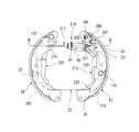
- first shoes 503 and a second shoe 505 arranged to face an inner peripheral surface of a brake drum (not shown).
- the first shoe 503 and the second shoe 505 are elastically supported on the backing plate 511 by the first shoe hold device 507 and the second shoe hold device 509 so as to be relatively movable within a limited range. Further, the first shoe 503 and the second shoe 505 are elastically biased in a direction approaching each other by a pair of the first shoe return spring 513 and the second shoe return spring 515.
- the adjacent ends of the first shoe 503 and the second shoe 505 in the lower part of FIG. 15 are in contact with anchors 517 attached and fixed to the backing plate 511.
- first shoe 503 and the second shoe 505 in the upper part of FIG. 15 can be pushed by the first piston 521 and the second piston 523 of the wheel cylinder 519 as a fluid actuator attached to the backing plate 511, respectively.
- first shoe 503 and the second shoe 505 are configured to expand.
- a forward pull type first parking brake lever 529 is pivotally supported on the second shoe 505 via a pin 527 on the second web 525 on the end side close to the wheel cylinder 519.
- the first parking brake lever 529 constituting the mechanical actuator (expansion mechanism) is rotatable in a plane perpendicular to the drum axis.
- a parking brake cable (not shown) is connected to the free end 531 of the first parking brake lever 529. When the parking brake cable is pulled by the parking brake operating force, the free end 531 of the first parking brake lever 529 is displaced in the direction indicated by W. Accordingly, the first parking brake lever 529 is configured to rotate around the pin 527 in the corresponding direction.
- the first parking brake lever 529 expands the second shoe 505 around the contact point with the anchor 517 on the one hand via the pin 527 and on the other hand moves the second parking brake lever 535 around the protrusion 537 via the strut 533.
- an expansion mechanism for expanding the first shoe 503 around the contact point with the anchor 517 via the projection 537 is configured.
- the dual mode drum brake device 501 becomes a duo-servo type drum brake during parking brake.
- the first parking brake lever 529 constituting the expansion mechanism is provided with the second shoe via the pin 527 in order to become a duo-servo type drum brake at the time of parking brake.
- 505 is expanded around the contact point with the anchor 517 and, on the other hand, the first shoe 503 is moved around the contact point with the anchor 517 via the protrusion 537 in order to rotate the second parking brake lever 535 via the strut 533.
- the strut 533 pressed by the first parking brake lever 529 presses the second parking brake lever 535.
- the first shoe 503 since the first shoe 503 is rotatably fitted to the second parking brake lever 535 and the protrusion 537 serving as the rotation center, the first shoe 503 is in contact with the anchor 517.
- the load of the return spring 513 needs to be larger than the load of the second shoe return spring 515. Therefore, the contact force of the first shoe 503 and the second shoe 505 to the anchor 517 is increased. Therefore, in order to stabilize the braking force at the time of service braking, when an anchor 517 with which the adjacent ends of the first shoe 503 and the second shoe 505 are in contact with each other in the lower part of the drawing is provided with an inclination during running, etc. Therefore, there is a possibility that the second shoe 505 and the first shoe 503 move toward the wheel cylinder 519 to cause dragging.
- the present invention has been made in view of the above situation, and an object of the present invention is to provide a drum brake device capable of enhancing the stability of the parking braking force in the dual mode brake structure.
- a pair of brake shoes disposed so as to oppose the inner peripheral surface of the brake drum and elastically supported so as to be movable on a backing plate, and interposed between one adjacent ends of the pair of brake shoes, A wheel cylinder for expanding each of the brake shoes, an anchor portion fixed to the backing plate and in contact with the other adjacent end of the pair of brake shoes, and the pair of brake shoes in the vicinity of the wheel cylinder
- An adjuster for adjusting a shoe interval, and an expansion mechanism that is arranged in series with the adjuster and that expands each of the pair of brake shoes by inputting an operation force.
- a switching lever that is rotatably provided on one brake shoe and is rotated by an action force that is greater than or equal to a predetermined value of the expansion mechanism.
- a switching strut provided between a mechanism and an adjacent end on the anchor portion side of the pair of brake shoes, and expanding an adjacent end on the anchor portion side of the pair of brake shoes in accordance with the rotation of the switching lever mechanism;
- a drum brake device comprising:
- the drum brake device having the above configuration (1)
- one adjacent end of the pair of brake shoes is expanded through the adjuster by an input from the expansion mechanism.
- One adjacent end of the pair of expanded brake shoes comes into contact with the inner peripheral surface of the brake drum, and a reaction force from the inner peripheral surface acts on the pair of brake shoes to exert an acting force of the expansion mechanism (expanding force).
- the switching lever mechanism expands the adjacent ends on the anchor portion side of the pair of brake shoes via the switching struts, and the pair of brake shoes is pressed against the inner peripheral surface of the brake drum.
- the switching lever mechanism arranged for switching the mode depending on the operation of expanding the brake shoe for parking brake Does not rotate and the mode switching mechanism does not operate. Therefore, after the one of the adjacent ends of the pair of brake shoes is expanded and brought into contact with the inner peripheral surface of the brake drum by the acting force of the expanding mechanism, the switching lever mechanism is adjacent to the anchor portion side of the pair of brake shoes. Since the end is expanded and contacts the inner peripheral surface of the brake drum, the adhesion between the pair of brake shoes and the drum sliding surface is improved.
- the pair of brake shoes are expanded on both the wheel cylinder side and the anchor portion side, and the adhesion to the drum sliding surface is improved.
- a high parking braking force as a duo servo is obtained, and loosening that occurs when the parking braking force is generated is prevented.
- the switching lever mechanism is rotatably supported by the pair of clamping portions respectively positioned on the front and back side surfaces of the first web. Therefore, when the switching lever mechanism is rotated, an uneven load is not applied to the first web, and a smooth rotation operation is possible.
- the drum brake device having the above-described configuration (1), wherein the switching lever mechanism includes a side end that engages with the expansion mechanism and a side end that engages with the switching strut.
- a drum brake device formed by bending so as to be positioned on opposite sides of a first web in a shoe.
- the anchor portion is connected to the parking brake cable or the like for operating the expansion mechanism.
- the side end of the switching lever mechanism that engages with the switching strut to avoid interference is disposed on the side opposite to the backing plate.
- a side end that engages with the expansion mechanism is disposed on the backing plate side in order to avoid interference with the adjuster. Therefore, the switching lever mechanism can be easily attached to the first web.
- the drum brake device having the above-described configuration (1), wherein the switching lever mechanism is rotatably supported on the one brake shoe by a first fulcrum pin and serves as an input side; A second switching lever that is rotatably supported by the one brake shoe by two fulcrum pins and that is an output side that rotates following the first switching lever, and the first switching lever includes the first switching lever.
- a drum brake device that receives an acting force from the expansion mechanism between a sliding contact between the switching lever and the second switching lever and the first fulcrum pin.
- each sliding contact In the first switching lever and the second switching lever, the positions of the first fulcrum pin and the second fulcrum pin and the sliding contact positions where the first switching lever and the second switching lever abut each other are set. Appropriate transmission ratios of the first and second switching levers can be easily selected, and optimal adhesion between the pair of brake shoes and the drum sliding surface can be easily obtained. Further, in the first switching lever and the second switching lever, the position of the first fulcrum pin and the second fulcrum pin and the length of each lever can be set as appropriate, and the degree of freedom of layout in the brake drum of the switching lever mechanism Is expensive.
- the second switching lever has a pair of sandwiching portions formed to bend so as to sandwich the first web of the one brake shoe, A drum brake device in which the pair of clamping portions are rotatably supported by the first web.
- the second switching lever is rotatably supported by the pair of clamping portions respectively positioned on the front and back side surfaces of the first web. Therefore, when the second switching lever is rotated, an uneven load is not applied to the first web, and a smooth rotation operation is possible.
- the drum brake device having the configuration of (4), wherein the second switching lever has a side end in contact with the first switching lever and a side end in contact with the switching strut, the one brake shoe.
- a drum brake device that is bent so as to be positioned on opposite sides of the first web.
- the anchor portion is connected to the parking brake cable or the like that operates the expansion mechanism.
- the side end of the second switching lever that contacts the switching strut is disposed on the side opposite to the backing plate.
- the first switching lever is disposed on the backing plate side in order to avoid interference with the adjuster, and the side end of the second switching lever that contacts the first switching lever is disposed on the backing plate side. . Therefore, the first and second switching levers can be easily attached to the first web.
- a driving mechanism that pulls and drives a parking cable connected to the expansion mechanism is provided on the back side surface of the backing plate.
- a drum brake device arranged.
- the expansion mechanism can be operated electrically by pulling the parking cable by the drive mechanism disposed on the back side surface of the backing plate. And since it becomes a duo servo at the time of parking brake, high effectiveness (power saving) is implement
- FIG. 1 is a front view of a drum brake device (cross-pull type) according to a first embodiment of the present invention.
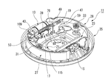
- FIG. 2A is a front perspective view of the drum brake device shown in FIG.
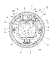
- FIG. 2B is a rear perspective view of the drum brake device shown in FIG. 1.
- 3 is a cross-sectional view taken along the line III-III in FIG. 4A is a perspective view of a main part of the drum brake device shown in FIG. 2A.
- 4B is a perspective view of the drum brake device shown in FIG. 4A as viewed from the back side.
- FIG. 5A is a front view of the main part of the drum brake device shown in FIG. 4A as viewed from the front side.
- FIG. 5B is a rear view of the drum brake device shown in FIG.
- FIG. 6 is a front view of a drum brake device (forward pull type) according to a second embodiment of the present invention.
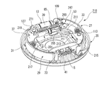
- 7 is a front perspective view of the drum brake device shown in FIG.
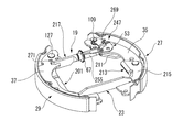
- FIG. 8A is a perspective view of a main part of the drum brake device shown in FIG.
- FIG. 8B is a perspective view of the drum brake device shown in FIG. 8A as viewed from the back side.
- FIG. 9 is a front view of the main part of the drum brake device shown in FIG. 8A as viewed from the front side.
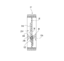
- 10 is a cross-sectional view taken along the line XX of FIG.
- FIG. 11 is an exploded perspective view of a main part of the drum brake device shown in FIG. FIG.
- FIG. 12 is an exploded perspective view of main parts showing a modification of the switching lever mechanism shown in FIG.
- FIG. 13 is an assembly front view of the main part of the switching lever mechanism shown in FIG. 14 is a cross-sectional view taken along the line XIV-XIV in FIG.
- FIG. 15 is a front view of a conventional dual mode drum brake device.
- the drum brake device 11 includes a first brake shoe 27 and a second brake shoe 29 that are a pair of brake shoes, a wheel cylinder 13, an anchor, and an anchor.
- the part 15, the adjuster 17, the cross-pull type spreading mechanism 19, the switching lever mechanism 21, and the switching strut 23 are configured as main members.
- the drum brake device 11 is integrally fixed to the vehicle body in such a posture that the backing plate 25 is substantially perpendicular to a rotation axis of a wheel (not shown).
- a pair of first brake shoes 27 and second brake shoes 29, each having a substantially arc shape are arranged vertically along the left and right outer peripheral edges.
- the first brake shoe 27 and the second brake shoe 29 are elastically supported by the first shoe hold device 31 and the second shoe hold device 33 so that the first web 35 and the second web 37 can move, and can be expanded. It has become.
- the first brake shoe 27 and the second brake shoe 29 are elastically urged in a direction approaching each other by a pair of first shoe return springs 39 and second shoe return springs 41.
- a wheel cylinder 13 as a fluid actuator is interposed between adjacent ends of the first brake shoe 27 and the second brake shoe 29 in the upper part of FIG.
- the wheel cylinder 13 is attached to the backing plate 25, and the first and second brake shoes 27 and 29 are expanded by pushing the first piston 43 and the second piston 45 in the direction away from each other. To do.
- the other adjacent ends of the first brake shoe 27 and the second brake shoe 29 in the lower part of FIG. 1 abut against a fixed anchor portion 15 attached to the backing plate 25.
- the first brake shoe 27 and the second brake shoe 29 are shown in FIG. 1 by the first piston 43 and the second piston 45 that are pressurized and operated from both ends thereof. Is expanded and rotated around the contact point with the anchor portion 15. As a result, the first brake shoe 27 and the second brake shoe 29 are frictionally engaged with an inner peripheral surface of a brake drum (not shown) to brake it.
- one of the first brake shoe 27 and the second brake shoe 29 is a leading shoe with respect to the rotation direction of the brake drum and has a self-servo property, and the other is a trailing shoe with respect to the rotation direction of the brake drum. Therefore, it does not have self-servo properties.
- the drum brake device 11 functions as a leading / trailing drum brake.
- the adjuster 17 includes an expansion mechanism 19 that expands each of the first brake shoe 27 and the second brake shoe 29 when an operating force is input to the backing plate 25 in the vertical direction via the parking cable 51. They are arranged in series.
- the adjuster 17 and the expansion mechanism 19 constitute a parking lever assembly 47 with an adjuster.
- the adjuster-equipped parking lever assembly 47 is disposed across one adjacent end of the first brake shoe 27 and the second brake shoe 29, and the parking lever 49 is moved in one direction.
- the pair of first brake shoes 27 and second brake shoes 29 are mechanically separated.
- a parking cable 51 is connected to the parking lever 49, and the parking cable 51 rotates the parking lever 49 in one direction in accordance with the operation force of the parking brake operation.
- the adjuster-attached parking lever assembly 47 includes an adjuster 17 and an expansion mechanism 19. Further, the adjuster 17 includes an adjuster lever 53 (see FIG. 1) and a strut 55. On the other hand, the expansion mechanism 19 includes a lever pin 57, a parking lever 49, and a bracket 59. The adjuster 17 is provided with a shoe gap automatic adjusting mechanism, and expands and contracts in the axial direction by an adjuster screw 61 (see FIG. 3).
- the adjuster lever 53 is pivotally supported by the first fulcrum pin 109 (see FIG. 1) so as to be able to rotate to the first web 35 of the first brake shoe 27.
- a first shoe return spring 39 is stretched between the adjuster lever 53 and the second brake shoe 29, and urges the adjuster lever 53 to rotate counterclockwise in FIG. Further, the arm portion 65 of the adjuster lever 53 is rotationally engaged with the toothed wheel 67 of the strut 55 by this rotation biasing force.
- the strut 55 has an adjuster socket 69 on one end side (left end side in FIG. 3) with the adjuster screw 61 interposed therebetween, and an engagement plate portion 71 on the other end side (right end side in FIG. 3).
- the adjuster socket 69 is in contact with the first web 35 of the first brake shoe 27.
- the engaging plate portion 71 engages with a concave contact portion 73 that is a rotating portion of the parking lever 49.
- the parking lever 49 has a pin engagement hole 75 through which the lever pin 57 serving as a rotation fulcrum is inserted above the concave contact portion 73.
- the parking lever 49 has a cable hooking portion 77 formed on the opposite side of the concave contact portion 73 (side driven by the parking cable 51).
- a lever pin 57 which is a rotation fulcrum of the parking lever 49 is arranged on the center side of the expansion mechanism (the center side in the left-right direction in FIG. 3).
- the side driven by the parking cable 51 of the parking lever 49 is arranged close to the second brake shoe 29 side.
- a bracket 59 in which one end 79 of the bracket holds the lever pin 57 that is the rotation fulcrum of the parking lever 49 and the other end 81 of the bracket abuts against the second brake shoe 29 is an insertion hole 83 that is a lead-out portion of the parking cable 51. It is slidably contacted to the backing plate 25 side on both sides of the side (see FIG. 3).
- the bracket 59 of the first embodiment has two plate portions 85 that sandwich the parking lever 49.
- An engaging recess 87 is formed in the bracket other end portion 81, and the engaging recess 87 abuts on the second web 37 of the second brake shoe 29.
- a protrusion 89 is formed on the side of the bracket one end 79 that holds the lever pin 57, and the protrusion 89 has a disengagement prevention mechanism that prevents the other end of the strut 55 from coming off from the concave contact portion 73 of the parking lever 49.
- An oval holding groove 91 that holds the lever pin 57 is formed above the protruding portion 89.
- the width of the bracket 59 on the side where the protruding portion 89 is formed is narrower than the outer diameter of the strut cylindrical portion 93. Accordingly, the strut cylindrical portion 93 is locked to the protruding portion 89 of the bracket 59, and the engagement plate portion 71 is prevented from being detached from the concave contact portion 73.
- the engagement plate portion 71 of the strut 55 is engaged with the concave contact portion 73.
- the parking lever 49 engaged with the strut 55 is inserted between the pair of plate portions 85 of the bracket 59.
- the parking lever 49 inserted into the bracket 59 is rotated around the lever pin 57 while the lever pin 57 is supported by the oval holding groove 91.
- a backing plate side contact portion 95 (see FIG. 3) is brought into contact with the backing plate 25 directly or via a contact member.
- the backing plate side contact portion 95 is brought into contact with the backing plate 25 via a lever plate 97 (see FIG. 3) that is a contact member.
- the backing plate 25 is provided with an insertion hole 83 (see FIG. 3) through which the parking cable 51 is inserted as a lead-out portion of the parking cable 51.
- the lever plate 97 is mounted on the wheel side surface of the backing plate 25 so as to overlap the insertion hole 83, and the lever plate 97 has a through hole 99 (see FIG. 3) that coincides with the insertion hole 83.
- a cable anchor 103 which is a parking cable anchor member, is disposed at the same center as the insertion hole 83.
- a cable case 105 is fixed to the tip of the cable anchor 103 at the same center, and the parking cable 51 led out from the cable case 105 passes through the insertion hole 83 and the through hole 99 and is hooked to the parking lever 49.
- a cable boot 107 (see FIG. 3) is fixed to the cable case 105 inside the cable anchor 103, and the parking cable 51 is inserted into the cable boot 107 inward.
- the cable anchor 103 fixed to the backing plate 25 is disposed between the backing plate 25 and the cable case 105. Since the parking cable 51 is pulled downward in FIG. 3, the cable case 105 inputs an upward force as a reaction force to the cable anchor 103 to the cable anchor 103. Accordingly, the cable acting force is received by the backing plate 25 in the thickness direction of the backing plate 25 and in the approaching direction facing each other with the cable anchor 103 interposed therebetween, and the cable anchor 103 can be advantageously configured in terms of attachment strength.
- a switching lever mechanism 21 is rotatably provided on a first brake shoe 27 that is one brake shoe.
- the switching lever mechanism 21 is rotated by an action force (expansion force) greater than or equal to a predetermined value of the expansion mechanism 19.
- a switching strut 23 is provided between adjacent ends of the first brake shoe 27 and the second brake shoe 29 on the anchor portion 15 side. The switching strut 23 expands against the urging force of the second shoe return spring 41 at the adjacent end of the first brake shoe 27 and the second brake shoe 29 on the anchor portion 15 side following the rotation of the switching lever mechanism 21. To do.
- the switching lever mechanism 21 is rotatable to one end side (wheel cylinder 13 side) of the first brake shoe 27 by the first fulcrum pin 109 as shown in FIGS. 5A and 5B.
- a first switching lever 111 that is supported and serves as an input side, and a second fulcrum pin 113 that is rotatably supported at a substantially middle portion of the first brake shoe 27 and that is a first output lever that rotates following the first switching lever 111.
- 2 switching lever 115 The first switching lever 111 receives an acting force from the expansion mechanism 19 between the sliding contact between the first switching lever 111 and the second switching lever 115 and the first fulcrum pin 109.
- the switching strut 23 that is driven by the rotation of the first switching lever 111 and the second switching lever 115 is the first.
- the distance between the fulcrum, the force point, and the action point is set so that the adjacent ends of the first brake shoe 27 and the second brake shoe 29 on the anchor portion 15 side are expanded against the urging force of the second shoe return spring 41. Has been.
- the adjuster socket 69 and the first switching lever 111 are in contact with each other at the first sliding contact 117, and the first switching lever 111 and the first switching lever 111 are in contact with each other.
- the second switching lever 115 is in contact with the second sliding contact 119, and the second switching lever 115 and the switching strut 23 are in contact with the third sliding contact 121.
- the distance is A
- the distance between the first fulcrum pin 109 and the second sliding contact 119 along the virtual center line 123 is B
- the distance between the second fulcrum pin 113 and the third sliding contact 121 in the direction along the virtual center line 123 is D. Therefore, each distance is set to 1 ⁇ (A / B) ⁇ (C / D) ⁇ 3.
- the wheel cylinder 13 side of the first brake shoe 27 and the second brake shoe 29 is first expanded by the input from the expansion mechanism 19 and comes into contact with the inner peripheral surface of the brake drum.
- the reaction force from the inner peripheral surface acts on the first brake shoe 27 and the second brake shoe 29, so that the acting force (expanding force) of the expanding mechanism 19 is not less than a predetermined value.
- the first switching lever 111 and the second switching lever 115 are configured to rotate and transmit the acting force to the switching strut 23.
- the operation of the drum brake device 11 having the above configuration will be described.
- the parking cable 51 is pulled according to the operation of an operation member (such as an operation lever) in the vehicle interior from the state before the parking operation
- the parking with the adjuster is performed in the initial operation.
- the adjacent ends of the first brake shoe 27 and the second brake shoe 29 on the wheel cylinder 13 side are first expanded by the lever assembly 47, and the positions of the first brake shoe 27 and the second brake shoe 29 are determined.
- the acting force (expanding force) of the spreading mechanism 19 acts on the first brake shoe 27 and the second brake shoe 29 and exceeds a predetermined value
- the first switching lever 111 rotates and the first switching lever 111 performs the second switching.
- the lever 115 is pressed. Therefore, the second switching lever 115 rotates about the second fulcrum pin 113 counterclockwise in FIG.
- the second switching lever 115 presses the second brake shoe 29 via the switching strut 23.
- the adjacent ends of the first brake shoe 27 and the second brake shoe 29 on the anchor portion 15 side are expanded and pressed against the inner peripheral surface of the brake drum.
- the switching lever mechanism 21 including the first switching lever 111 and the second switching lever 115 provided for mode switching does not rotate, and the mode switching mechanism It does not work. Therefore, the switching lever mechanism is provided after the adjacent ends of the first brake shoe 27 and the second brake shoe 29 on the wheel cylinder 13 side are expanded and abutted against the inner peripheral surface of the brake drum by the acting force of the expansion mechanism 19. 21, the adjacent ends of the first brake shoe 27 and the second brake shoe 29 on the anchor portion 15 side are expanded and contact the inner peripheral surface of the brake drum. Therefore, the adhesion between the first brake shoe 27 and the second brake shoe 29 and the drum sliding surface is improved.
- the first brake shoe 27 and the second brake shoe 29 are expanded on both the wheel cylinder 13 side and the anchor portion 15 side, and the drum slide Adhesion to the moving surface is improved.
- a high parking braking force as a duo servo is obtained, and loosening that occurs when the parking braking force is generated is prevented.
- the first to third sliding contacts 117, 119, 121 are transmitted in the transmission of the acting force.
- the amount of displacement is reduced. For this reason, problems such as wear are unlikely to occur.
- the positions of the first fulcrum pin 109 and the second fulcrum pin 113, and the first to the second switching levers 115 abut on each other.
- first switching lever 111 and the second switching lever 115 the positions of the first fulcrum pin 109 and the second fulcrum pin 113 and the lengths of the first switching lever 111 and the second switching lever 115 are appropriately set. And the degree of freedom of layout in the brake drum of the switching lever mechanism 21 is high.
- the drum brake device 11 is disposed on the back side surface 101 of the backing plate 25 and has a motor gear unit 125 as a drive mechanism that pulls and drives the parking cable 51 connected to the expansion mechanism 19.
- a drum brake device including an electric parking brake can be obtained.
- the expansion mechanism 19 can be operated electrically. As described above, high efficiency (power saving) is realized because the duo-servo drum brake is used during parking brake.
- a dual mode brake structure that functions as a leading / trailing type at the time of service brake and a duo servo type at the time of parking brake can be configured at low cost. Further, according to the drum brake device 11 according to the present embodiment, the parking brake can be easily electrified.
- the drum brake device 210 according to the second embodiment is provided with a dual mode brake structure, like the drum brake device 11 according to the first embodiment.
- symbol is attached
- the drum brake device 210 of the second embodiment uses a forward-pull type expansion mechanism 219 instead of the cross-pull type expansion mechanism 19 used in the drum brake device 11 shown in the first embodiment.
- the adjuster 217 is arranged in series.
- the adjuster 217 and the expansion mechanism 219 constitute a parking lever assembly 247 with an adjuster.
- the adjuster-equipped parking lever assembly 247 is disposed across one adjacent end of the first brake shoe 27 and the second brake shoe 29, and the parking brake lever 201. Is rotated in one direction to mechanically separate the first brake shoe 27 and the second brake shoe 29 from each other.
- the parking brake lever 201 is pivotally supported by the second web 37 on the end side near the wheel cylinder 13 of the second brake shoe 29 via a pin 127 so as to be rotatable in a plane perpendicular to the drum axis.
- a parking brake cable (not shown) is connected to the free end 203 of the parking brake lever 201, and the free end 203 of the parking brake lever 201 is moved in the direction indicated by W by pulling the parking brake cable with the parking brake operating force. Displaced.
- the parking brake lever 201 on the one hand, the second brake shoe 29 expands around the contact point with the anchor portion 15 via the pin 127, and on the other hand, the first brake shoe 27 moves to the anchor portion 15 via the adjuster 217.
- the forward pull type expansion mechanism 219 is configured to expand around the contact point.
- the adjuster 217 includes an adjuster lever 53 and a strut 255 and includes an automatic shoe clearance adjustment mechanism, and is extended and contracted in the axial direction by an adjuster screw 61 (see FIG. 10).
- the strut 255 has an adjuster socket 269 on one end side (right end side in FIG. 10) with the adjuster screw 61 interposed therebetween, and is engaged with the first web 35 of the first brake shoe 27. Further, the other end portion side (the left end side in FIG. 10) of the strut 255 sandwiching the adjuster screw 61 is an engagement plate portion 271, and is engaged with the second web 37 of the second brake shoe 29.
- a switching lever mechanism 213 is rotatably provided on the first brake shoe 27 which is one of the brake shoes, and the switching lever mechanism 213 is an expansion mechanism. 219 is rotated by an action force (expansion force) exceeding a predetermined value.
- a switching strut 23 is provided between adjacent ends of the first brake shoe 27 and the second brake shoe 29 on the anchor portion 15 side. The switching strut 23 expands against the urging force of the second shoe return spring 41 at the adjacent end of the first brake shoe 27 and the second brake shoe 29 on the anchor portion 15 side following the rotation of the switching lever mechanism 213. To do.
- the switching lever mechanism 213 is rotatable to one end side (wheel cylinder 13 side) of the first brake shoe 27 by the first fulcrum pin 109.
- a first switching lever 211 that is supported and serves as an input side, and a second fulcrum pin 113 that is rotatably supported at a substantially middle portion of the first brake shoe 27 and that is an output side that rotates following the first switching lever 211.
- the first switching lever 211 receives an acting force from the expansion mechanism 219 between the sliding contact between the first switching lever 211 and the second switching lever 215 and the first fulcrum pin 109.
- the switching strut 23 that is driven by the rotation of the first switching lever 211 and the second switching lever 215 is the first.
- the distance between the fulcrum, the force point, and the action point is such that the adjacent ends of the first brake shoe 27 and the second brake shoe 29 on the anchor portion 15 side are expanded against the urging force of the second shoe return spring 41. Is set.
- the adjuster socket 269 and the first switching lever 211 are in contact with each other at the first sliding contact 227, and the first switching lever 211 and the first switching lever 211 are in contact with each other.
- the second switching lever 215 is in contact with the second sliding contact 229, and the second switching lever 215 and the switching strut 23 are in contact with the third sliding contact 221.
- the side end 215a that contacts the first switching lever 211 is along the back side surface of the first web 35, and the side end 215b that contacts the switching strut 23 is the first.
- the web 35 is bent along the front side surface and attached so as to sandwich the first web 35 (see FIG. 11).
- the wheel cylinder 13 side of the first brake shoe 27 and the second brake shoe 29 is first expanded by the input from the expansion mechanism 219, and the inner peripheral surface of the brake drum. After the positions of the first brake shoe 27 and the second brake shoe 29 are determined, the reaction force from the inner peripheral surface acts on the first brake shoe 27 and the second brake shoe 29 to expand the expansion mechanism 219.
- the first switching lever 211 and the second switching lever 215 are rotated so that the acting force is transmitted to the switching strut 23 when the acting force (expansion force) becomes equal to or greater than a predetermined value.
- the second switching lever 215 includes a side end 215 a that contacts the first switching lever 211 and a side end 215 b that contacts the switching strut 23. 35 is formed so as to be located on opposite sides of each other. Therefore, as shown in FIG. 6, when the adjuster 217 is disposed on the opposite side of the backing plate 25 with the first web 35 interposed therebetween, the anchor brake unit 201 operates the parking brake lever 201 that operates the expansion mechanism 219. In order to avoid interference with the connected parking brake cable, the side end 215 b of the second switching lever that contacts the switching strut 23 is disposed on the side opposite to the backing plate 25.
- the first switching lever 211 is disposed on the backing plate 25 side, and the side end 215a of the second switching lever 215 that contacts the first switching lever 211 is provided. , Arranged on the backing plate 25 side. Therefore, the first switching lever 211 and the second switching lever 215 can be easily attached to the first web 35.
- the second switching lever 215 has a pair of sandwiching portions 218 that are bent so as to sandwich the first web 35, and the through holes 216 of the pair of sandwiching portions 218 and the second
- the first web 35 is rotatably supported by a second fulcrum pin 113 inserted into the support hole 36 of the first web 35.
- the second fulcrum pin 113 that penetrates the pair of sandwiching portions 218 is prevented from coming off by the C clip 116 at the penetrating end. Therefore, the second switching lever 215 is rotatably supported by a pair of sandwiching portions 218 that are respectively located on the front and back side surfaces of the first web 35. Therefore, when the second switching lever 215 is rotated, an uneven load is not applied to the first web 35, and a smooth rotation operation is possible.
- a switching lever mechanism 231 that is rotatably provided on the first brake shoe 27 and is rotated by an action force greater than or equal to a predetermined value of the expansion mechanism 219 includes a first switching lever 211, a first switching lever 211, and a first switching lever 211. And a second switching lever 233 on the output side that is rotatably supported by the two fulcrum pins 122 at a substantially middle portion of the first brake shoe 27 and is rotated by the first switching lever 211.
- the second switching lever 233 is formed so that a side end 233a that contacts the first switching lever 211 and a side end 233b that contacts the switching strut 23 are located on opposite sides of the first web 35. . Therefore, similarly to the switching lever mechanism 213, the first switching lever 211 and the second switching lever 233 constituting the switching lever mechanism 231 can be easily attached to the first web 35.
- the second switching lever 233 has a pair of sandwiching portions 238 that are bent so as to sandwich the first web 35, and the notch holes 235 and 236 of the pair of sandwiching portions 238 and the first web 35.
- a second fulcrum pin 122 inserted into the support hole 36 is rotatably supported by the first web 35. Therefore, as with the switching lever mechanism 213, the second switching lever 233 can be smoothly rotated without applying an uneven load to the first web 35 when the second switching lever 233 is rotated. It becomes.
- the second fulcrum pin 122 is a stepped pin whose both ends are small diameter portions 122b with respect to the central large diameter portion 122a.
- the large diameter portion 122 a has an outer diameter substantially equal to the inner diameter of the support hole 36 and an axial width substantially equal to the plate thickness of the first web 35.
- the small diameter portion 122b has an outer diameter substantially equal to the opening width of the cutout holes 235 and 236.
- the large diameter portion 122 a of the second fulcrum pin 122 is fitted into the support hole 36.
- the pair of sandwiching portions 238 is inserted into the first web such that the small diameter portions 122b projecting from the support holes 36 to the front and back sides of the first web 35 are inserted from the notch opening end sides of the notches 235 and 236, respectively. Attach to 35.
- the second switching lever 233 attached to the first web 35 is configured such that the shaft portion of the second shoe hold device 33 that passes through the through hole 38 of the first web 35 is loosely fitted into the through hole 240, thereby
- the second fulcrum pin 122 is rotatably supported in a state in which movement relative to 35 is restricted. At this time, the second fulcrum pin 122 is prevented from coming off by locking the axial step of the large diameter portion 122a to the inner edge of the notches 235 and 236. Need not be used (see FIG. 14).
- the operation of the drum brake device 210 having the above configuration will be described.
- the parking lever assembly with an adjuster is initially set in the operation.
- the adjacent ends of the first brake shoe 27 and the second brake shoe 29 on the wheel cylinder 13 side are first expanded by the solid 247, and the positions of the first brake shoe 27 and the second brake shoe 29 are determined.
- the acting force (expanding force) of the expansion mechanism 219 acts on the first brake shoe 27 and the second brake shoe 29 and exceeds a predetermined value
- the first switching lever 211 rotates and the first switching lever 211 performs the second switching.
- the lever 215 (233) is pressed. Therefore, the second switching lever 215 (233) rotates around the second fulcrum pin 113 (122) clockwise in FIG.
- the second switching lever 215 (233) presses the second brake shoe 29 via the switching strut 23.
- the adjacent ends of the first brake shoe 27 and the second brake shoe 29 on the anchor portion 15 side are expanded and pressed against the inner peripheral surface of the brake drum.
- the forward pull type expansion mechanism 219 for parking brake is used.
- the switching lever mechanism 213 (231) including the first switching lever 211 and the second switching lever 215 (233) arranged for mode switching rotates. And the mode switching mechanism does not operate. Therefore, the switching lever mechanism is provided after the adjacent ends of the first brake shoe 27 and the second brake shoe 29 on the wheel cylinder 13 side are expanded by the acting force of the expansion mechanism 219 and contact the inner peripheral surface of the brake drum.
- first brake shoe 27 and the second brake shoe 29 on the anchor portion 15 side are expanded by 213 (231) and come into contact with the inner peripheral surface of the brake drum, the first brake shoe 27 and the second brake shoe Adhesion between 29 and the drum sliding surface is improved.
- the drum brake device 210 of the second embodiment at the end of the parking operation, the first brake shoe 27 and the second brake shoe 29 are expanded both on the wheel cylinder 13 side and the anchor portion 15 side, and the drum slide Adhesion to the moving surface is improved.
- the parking brake is operated, a high parking braking force as a duo servo is obtained, and loosening that occurs when the parking braking force is generated is prevented.
- the drum brake device adds a mode switching mechanism regardless of the configuration difference between the cross-pull type spreading mechanism 19 and the forward-pull type spreading mechanism 219 having different parking cable pulling directions. be able to. Further, the cable attachment portion of the backing plate 25 can be provided at a general position, and the cost of the backing plate 25 can be prevented from being significantly increased without complicating the shape of the backing plate as in the prior art.
- a pair of brake shoes (first brake shoe and second brake shoe) 27 and 29 which are arranged so as to face the inner peripheral surface of the brake drum and are elastically supported so as to be movable on the backing plate 25, and the pair of brake shoes
- the brake shoes (first brake shoe and second brake shoe) 27 and 29 are interposed between adjacent ends, and the pair of brake shoes (first brake shoe and second brake shoe) 27 and 29 are expanded.
- the pair of brake shoes (the first brake shoe and the first brake shoe) in the vicinity of the wheel cylinder 13 2 brake shoes) 27 and 29, which are interposed between the adjacent ends of the brake shoes 27 and 29, are arranged in series with the adjuster 17 for adjusting the shoe interval, and the pair of brake shoes ( (First brake shoe and second brake shoe) 27, 29, and an expansion mechanism 19 that expands each, and one brake shoe (first brake shoe) 27 is rotatably provided.
- the switching lever mechanism 21 rotated by the above acting force and the pair of brake shoes (first brake shoe and second brake shoe) 27, 29 are provided between adjacent ends on the anchor portion side, and the switching lever mechanism 21
- the adjacent ends of the pair of brake shoes (first brake shoe and second brake shoe) 27, 29 on the anchor portion 15 side following the rotation of Drum brake device 11 includes a switching strut 23, the to expansion.
- the switching lever mechanism 213 is rotatably supported on the one brake shoe (first brake shoe) 27 by the first fulcrum pin 109 and input.
- the first switching lever 211 on the side and the second fulcrum pin 113 are rotatably supported by the one brake shoe (first brake shoe) 27 and become the output side that rotates following the first switching lever 211.
- a second switching lever 215, and the first switching lever 211 includes a sliding contact (second sliding contact) 229 between the first switching lever 211 and the second switching lever 215 and the first fulcrum pin 109.
- a drum brake device 210 that receives an acting force from the expansion mechanism 219. [3] In the drum brake device 210 configured as described in [2] above, the second switching lever 215 is bent so as to sandwich the first web 35 of the one brake shoe (first brake shoe) 27.
- a drum brake device 210 having a pair of sandwiched portions 218 that are rotatably supported by the first web 35.
- the second switching lever 215 includes a side end 233a that contacts the first switching lever 211 and a side end 233b that contacts the switching strut 23.
- the drum brake device 210 is formed by bending so that the first web 35 of the one brake shoe (first brake shoe) 27 is located on the opposite side of the first web 35.
- the drum brake devices 11 and 210 are provided with a drive mechanism (motor gear unit) 125 for pulling and driving.
- the drum brake device of the present invention is not limited to the above-described embodiment, and can be appropriately modified and improved.
- the material, shape, dimensions, number, arrangement location, and the like of each component in the above-described embodiment are arbitrary and are not limited as long as the present invention can be achieved.
- This application is based on a Japanese patent application filed on July 25, 2012 (Japanese Patent Application No. 2012-165005) and a Japanese patent application filed on May 17, 2013 (Japanese Patent Application No. 2013-105237). The contents are incorporated herein by reference.
- the dual mode brake structure that functions as a leading / trailing type at the time of service brake and a duo-servo type at the time of parking brake allows the service to be performed without causing a drag phenomenon due to running vibration during running.
- the braking force during braking can be stabilized.
Abstract
La présente invention concerne un dispositif de frein à tambour (11) pourvu de premier et second segments de frein (27, 29), d'un cylindre de roue (13), d'une section d'ancrage (15), d'un régleur (17), d'un mécanisme d'extension (19) qui étend le premier segment de frein (27) et le second segment de frein (29), d'un mécanisme de levier de commutation (21) qui est mis en rotation par la force d'actionnement du mécanisme d'extension (19) qui est supérieure ou égale à un niveau prédéterminé, et d'un étai de commutation (23) qui suit la rotation du mécanisme de levier de commutation (21) et étend les extrémités adjacentes des premier et second segments de frein (27, 29), les extrémités adjacentes étant en face de la section d'ancrage (15).
Priority Applications (3)
| Application Number | Priority Date | Filing Date | Title |
|---|---|---|---|
| US14/416,779 US9488234B2 (en) | 2012-07-25 | 2013-07-24 | Drum brake apparatus |
| EP13822767.3A EP2878850B1 (fr) | 2012-07-25 | 2013-07-24 | Dispositif de frein à tambour |
| CN201380039765.XA CN104508316B (zh) | 2012-07-25 | 2013-07-24 | 鼓式制动装置 |
Applications Claiming Priority (4)
| Application Number | Priority Date | Filing Date | Title |
|---|---|---|---|
| JP2012165005 | 2012-07-25 | ||
| JP2012-165005 | 2012-07-25 | ||
| JP2013-105237 | 2013-05-17 | ||
| JP2013105237A JP6114106B2 (ja) | 2012-07-25 | 2013-05-17 | ドラムブレーキ装置 |
Publications (1)
| Publication Number | Publication Date |
|---|---|
| WO2014017552A1 true WO2014017552A1 (fr) | 2014-01-30 |
Family
ID=49997361
Family Applications (1)
| Application Number | Title | Priority Date | Filing Date |
|---|---|---|---|
| PCT/JP2013/070083 WO2014017552A1 (fr) | 2012-07-25 | 2013-07-24 | Dispositif de frein à tambour |
Country Status (5)
| Country | Link |
|---|---|
| US (1) | US9488234B2 (fr) |
| EP (1) | EP2878850B1 (fr) |
| JP (1) | JP6114106B2 (fr) |
| CN (1) | CN104508316B (fr) |
| WO (1) | WO2014017552A1 (fr) |
Families Citing this family (11)
| Publication number | Priority date | Publication date | Assignee | Title |
|---|---|---|---|---|
| KR102066700B1 (ko) | 2015-07-30 | 2020-01-15 | 주식회사 엘지화학 | 심 플레이트 |
| CN105351396A (zh) * | 2015-12-10 | 2016-02-24 | 安徽江淮汽车股份有限公司 | 一种领从蹄式制动器 |
| FR3057317B1 (fr) * | 2016-10-12 | 2020-10-30 | Foundation Brakes France | Frein a tambour integrant un levier d'actionnement de frein de stationnement a double flancs encliquetes l'un avec l'autre |
| FR3057318B1 (fr) * | 2016-10-12 | 2020-08-14 | Foundation Brakes France | Frein a tambour integrant un levier d'actionnement de frein de stationnement a double flancs soudes |
| CN106438765B (zh) * | 2016-10-24 | 2018-08-07 | 广州中博制动系统有限公司 | 可防止制动蹄下坠的盘中鼓式制动器 |
| US11060572B2 (en) * | 2017-02-07 | 2021-07-13 | ZF Active Safety US Inc. | Electric actuator assembly for a drum brake assembly |
| JP6795426B2 (ja) * | 2017-02-23 | 2020-12-02 | 曙ブレーキ工業株式会社 | ドラムブレーキ装置 |
| JP6651482B2 (ja) * | 2017-06-23 | 2020-02-19 | 日信工業株式会社 | ドラムブレーキ装置 |
| JP7087565B2 (ja) * | 2018-03-29 | 2022-06-21 | 株式会社アドヴィックス | ブレーキ装置 |
| KR102176060B1 (ko) * | 2019-01-03 | 2020-11-09 | 현대모비스 주식회사 | 차량용 드럼 브레이크장치 |
| DE102019207664B3 (de) * | 2019-05-24 | 2020-04-23 | Continental Teves Ag & Co. Ohg | Trommelbremse |
Citations (3)
| Publication number | Priority date | Publication date | Assignee | Title |
|---|---|---|---|---|
| JPH08502579A (ja) * | 1992-10-30 | 1996-03-19 | アライドシグナル ウーロープ セルビス テクニック | 機械的駆動ドラムブレーキ |
| JPH10508680A (ja) * | 1994-11-09 | 1998-08-25 | ボッシュ システム ド フラナージュ | ドラムブレーキ用機械的駆動装置 |
| JP2001343037A (ja) | 2000-06-01 | 2001-12-14 | Nisshinbo Ind Inc | デュアルモードドラムブレーキ装置 |
Family Cites Families (10)
| Publication number | Priority date | Publication date | Assignee | Title |
|---|---|---|---|---|
| JPS5020659B1 (fr) | 1967-11-14 | 1975-07-16 | ||
| US3708044A (en) * | 1971-05-18 | 1973-01-02 | Aisin Seiki | Vehicle expanding brake assembly |
| JP3838290B2 (ja) | 1996-06-28 | 2006-10-25 | トヨタ自動車株式会社 | デュアルモードドラムブレーキ |
| US6206148B1 (en) * | 1999-01-29 | 2001-03-27 | Robert Bosch Corporation | Drum brake with duo-actuation |
| JP3341155B2 (ja) * | 1999-02-23 | 2002-11-05 | 日清紡績株式会社 | デュアルモードドラムブレーキ装置 |
| US6374962B1 (en) * | 2001-07-27 | 2002-04-23 | Robert Bosch Corporation | Drum brake with dual-actuation |
| US6615957B2 (en) | 2001-08-02 | 2003-09-09 | Hosei Brake Ind. Co., Ltd. | Dual-mode drum brake assembly having provision for preventing disengagement of members to be mutually engaged |
| JP3933487B2 (ja) | 2002-02-14 | 2007-06-20 | 日清紡績株式会社 | デュアルモードドラムブレーキ装置 |
| JP2010173588A (ja) | 2009-01-30 | 2010-08-12 | Toyota Motor Corp | ブレーキ固着検出装置およびブレーキ固着解除装置 |
| JP2011099458A (ja) | 2009-11-04 | 2011-05-19 | Akebono Brake Ind Co Ltd | ドラムブレーキ式駐車ブレーキ装置 |
-
2013
- 2013-05-17 JP JP2013105237A patent/JP6114106B2/ja not_active Expired - Fee Related
- 2013-07-24 US US14/416,779 patent/US9488234B2/en active Active
- 2013-07-24 CN CN201380039765.XA patent/CN104508316B/zh active Active
- 2013-07-24 EP EP13822767.3A patent/EP2878850B1/fr not_active Not-in-force
- 2013-07-24 WO PCT/JP2013/070083 patent/WO2014017552A1/fr active Application Filing
Patent Citations (3)
| Publication number | Priority date | Publication date | Assignee | Title |
|---|---|---|---|---|
| JPH08502579A (ja) * | 1992-10-30 | 1996-03-19 | アライドシグナル ウーロープ セルビス テクニック | 機械的駆動ドラムブレーキ |
| JPH10508680A (ja) * | 1994-11-09 | 1998-08-25 | ボッシュ システム ド フラナージュ | ドラムブレーキ用機械的駆動装置 |
| JP2001343037A (ja) | 2000-06-01 | 2001-12-14 | Nisshinbo Ind Inc | デュアルモードドラムブレーキ装置 |
Also Published As
| Publication number | Publication date |
|---|---|
| EP2878850A1 (fr) | 2015-06-03 |
| US9488234B2 (en) | 2016-11-08 |
| JP6114106B2 (ja) | 2017-04-12 |
| JP2014040908A (ja) | 2014-03-06 |
| CN104508316B (zh) | 2017-03-08 |
| CN104508316A (zh) | 2015-04-08 |
| EP2878850B1 (fr) | 2018-07-18 |
| EP2878850A4 (fr) | 2016-06-29 |
| US20150176664A1 (en) | 2015-06-25 |
Similar Documents
| Publication | Publication Date | Title |
|---|---|---|
| WO2014017552A1 (fr) | Dispositif de frein à tambour | |
| EP0836028B1 (fr) | Frein à tambour | |
| US6523652B2 (en) | Drum brake device | |
| KR20200084553A (ko) | 차량용 드럼 브레이크장치 | |
| JP5877136B2 (ja) | パーキングブレーキ機構および電動パーキングブレーキ | |
| JP3936731B2 (ja) | 電動式ドラムブレーキ | |
| JP2002147506A (ja) | シュー間隙自動調節機構付きドラムブレーキ | |
| JP2015152126A (ja) | パーキングブレーキ機構および電動パーキングブレーキ | |
| JP4812689B2 (ja) | シュー間隙自動調節機構を備えたドラムブレーキ | |
| WO2018155655A1 (fr) | Dispositif de frein à tambour | |
| WO2017204234A1 (fr) | Frein à tambour de véhicule | |
| JP2016050630A (ja) | ドラムブレーキ装置 | |
| WO2018155654A1 (fr) | Dispositif de frein à tambour | |
| JP5950731B2 (ja) | パーキングブレーキ機構および電動パーキングブレーキ | |
| JP4813429B2 (ja) | ドラムブレーキ装置 | |
| JP6491543B2 (ja) | デュオサーボ型ドラムブレーキ | |
| JP6727102B2 (ja) | 車両用ブレーキ装置 | |
| JP3914911B2 (ja) | ドラムブレーキ装置 | |
| JP3909254B2 (ja) | ドラムブレーキ装置 | |
| CN110366645B (zh) | 鼓式制动器装置 | |
| JP4918419B2 (ja) | シュー間隙自動調節機構を備えたドラムブレーキ | |
| JP2000097268A (ja) | ドラムブレーキ装置 | |
| JP4555516B2 (ja) | デュアルモードドラムブレーキ | |
| JP4467848B2 (ja) | シュー間隙自動調節機構付ドラムブレーキ | |
| JP2005098322A (ja) | ドラムブレーキ装置 |
Legal Events
| Date | Code | Title | Description |
|---|---|---|---|
| 121 | Ep: the epo has been informed by wipo that ep was designated in this application |
Ref document number: 13822767 Country of ref document: EP Kind code of ref document: A1 |
|
| WWE | Wipo information: entry into national phase |
Ref document number: 14416779 Country of ref document: US Ref document number: 2013822767 Country of ref document: EP |
|
| NENP | Non-entry into the national phase |
Ref country code: DE |