WO2014017552A1 - Drum brake device - Google Patents
Drum brake device Download PDFInfo
- Publication number
- WO2014017552A1 WO2014017552A1 PCT/JP2013/070083 JP2013070083W WO2014017552A1 WO 2014017552 A1 WO2014017552 A1 WO 2014017552A1 JP 2013070083 W JP2013070083 W JP 2013070083W WO 2014017552 A1 WO2014017552 A1 WO 2014017552A1
- Authority
- WO
- WIPO (PCT)
- Prior art keywords
- brake
- switching lever
- shoe
- drum
- pair
- Prior art date
Links
Images


Classifications
-
- F—MECHANICAL ENGINEERING; LIGHTING; HEATING; WEAPONS; BLASTING
- F16—ENGINEERING ELEMENTS AND UNITS; GENERAL MEASURES FOR PRODUCING AND MAINTAINING EFFECTIVE FUNCTIONING OF MACHINES OR INSTALLATIONS; THERMAL INSULATION IN GENERAL
- F16D—COUPLINGS FOR TRANSMITTING ROTATION; CLUTCHES; BRAKES
- F16D51/00—Brakes with outwardly-movable braking members co-operating with the inner surface of a drum or the like
- F16D51/16—Brakes with outwardly-movable braking members co-operating with the inner surface of a drum or the like shaped as brake-shoes pivoted on a fixed or nearly-fixed axis
- F16D51/18—Brakes with outwardly-movable braking members co-operating with the inner surface of a drum or the like shaped as brake-shoes pivoted on a fixed or nearly-fixed axis with two brake-shoes
- F16D51/26—Brakes with outwardly-movable braking members co-operating with the inner surface of a drum or the like shaped as brake-shoes pivoted on a fixed or nearly-fixed axis with two brake-shoes both extending in the same direction from their pivots
- F16D51/28—Brakes with outwardly-movable braking members co-operating with the inner surface of a drum or the like shaped as brake-shoes pivoted on a fixed or nearly-fixed axis with two brake-shoes both extending in the same direction from their pivots mechanically actuated
-
- F—MECHANICAL ENGINEERING; LIGHTING; HEATING; WEAPONS; BLASTING
- F16—ENGINEERING ELEMENTS AND UNITS; GENERAL MEASURES FOR PRODUCING AND MAINTAINING EFFECTIVE FUNCTIONING OF MACHINES OR INSTALLATIONS; THERMAL INSULATION IN GENERAL
- F16D—COUPLINGS FOR TRANSMITTING ROTATION; CLUTCHES; BRAKES
- F16D51/00—Brakes with outwardly-movable braking members co-operating with the inner surface of a drum or the like
- F16D51/16—Brakes with outwardly-movable braking members co-operating with the inner surface of a drum or the like shaped as brake-shoes pivoted on a fixed or nearly-fixed axis
- F16D51/18—Brakes with outwardly-movable braking members co-operating with the inner surface of a drum or the like shaped as brake-shoes pivoted on a fixed or nearly-fixed axis with two brake-shoes
- F16D51/20—Brakes with outwardly-movable braking members co-operating with the inner surface of a drum or the like shaped as brake-shoes pivoted on a fixed or nearly-fixed axis with two brake-shoes extending in opposite directions from their pivots
- F16D51/24—Brakes with outwardly-movable braking members co-operating with the inner surface of a drum or the like shaped as brake-shoes pivoted on a fixed or nearly-fixed axis with two brake-shoes extending in opposite directions from their pivots fluid actuated
-
- F—MECHANICAL ENGINEERING; LIGHTING; HEATING; WEAPONS; BLASTING
- F16—ENGINEERING ELEMENTS AND UNITS; GENERAL MEASURES FOR PRODUCING AND MAINTAINING EFFECTIVE FUNCTIONING OF MACHINES OR INSTALLATIONS; THERMAL INSULATION IN GENERAL
- F16D—COUPLINGS FOR TRANSMITTING ROTATION; CLUTCHES; BRAKES
- F16D51/00—Brakes with outwardly-movable braking members co-operating with the inner surface of a drum or the like
- F16D51/16—Brakes with outwardly-movable braking members co-operating with the inner surface of a drum or the like shaped as brake-shoes pivoted on a fixed or nearly-fixed axis
- F16D51/18—Brakes with outwardly-movable braking members co-operating with the inner surface of a drum or the like shaped as brake-shoes pivoted on a fixed or nearly-fixed axis with two brake-shoes
- F16D51/26—Brakes with outwardly-movable braking members co-operating with the inner surface of a drum or the like shaped as brake-shoes pivoted on a fixed or nearly-fixed axis with two brake-shoes both extending in the same direction from their pivots
- F16D51/30—Brakes with outwardly-movable braking members co-operating with the inner surface of a drum or the like shaped as brake-shoes pivoted on a fixed or nearly-fixed axis with two brake-shoes both extending in the same direction from their pivots fluid actuated
-
- F—MECHANICAL ENGINEERING; LIGHTING; HEATING; WEAPONS; BLASTING
- F16—ENGINEERING ELEMENTS AND UNITS; GENERAL MEASURES FOR PRODUCING AND MAINTAINING EFFECTIVE FUNCTIONING OF MACHINES OR INSTALLATIONS; THERMAL INSULATION IN GENERAL
- F16D—COUPLINGS FOR TRANSMITTING ROTATION; CLUTCHES; BRAKES
- F16D51/00—Brakes with outwardly-movable braking members co-operating with the inner surface of a drum or the like
- F16D51/46—Self-tightening brakes with pivoted brake shoes, i.e. the braked member increases the braking action
- F16D51/48—Self-tightening brakes with pivoted brake shoes, i.e. the braked member increases the braking action with two linked or directly-interacting brake shoes
- F16D51/50—Self-tightening brakes with pivoted brake shoes, i.e. the braked member increases the braking action with two linked or directly-interacting brake shoes mechanically actuated
-
- F—MECHANICAL ENGINEERING; LIGHTING; HEATING; WEAPONS; BLASTING
- F16—ENGINEERING ELEMENTS AND UNITS; GENERAL MEASURES FOR PRODUCING AND MAINTAINING EFFECTIVE FUNCTIONING OF MACHINES OR INSTALLATIONS; THERMAL INSULATION IN GENERAL
- F16D—COUPLINGS FOR TRANSMITTING ROTATION; CLUTCHES; BRAKES
- F16D65/00—Parts or details
- F16D65/14—Actuating mechanisms for brakes; Means for initiating operation at a predetermined position
- F16D65/16—Actuating mechanisms for brakes; Means for initiating operation at a predetermined position arranged in or on the brake
- F16D65/22—Actuating mechanisms for brakes; Means for initiating operation at a predetermined position arranged in or on the brake adapted for pressing members apart, e.g. for drum brakes
-
- F—MECHANICAL ENGINEERING; LIGHTING; HEATING; WEAPONS; BLASTING
- F16—ENGINEERING ELEMENTS AND UNITS; GENERAL MEASURES FOR PRODUCING AND MAINTAINING EFFECTIVE FUNCTIONING OF MACHINES OR INSTALLATIONS; THERMAL INSULATION IN GENERAL
- F16D—COUPLINGS FOR TRANSMITTING ROTATION; CLUTCHES; BRAKES
- F16D65/00—Parts or details
- F16D65/38—Slack adjusters
- F16D65/40—Slack adjusters mechanical
- F16D65/52—Slack adjusters mechanical self-acting in one direction for adjusting excessive play
- F16D65/56—Slack adjusters mechanical self-acting in one direction for adjusting excessive play with screw-thread and nut
- F16D65/561—Slack adjusters mechanical self-acting in one direction for adjusting excessive play with screw-thread and nut for mounting within the confines of a drum brake
- F16D65/562—Slack adjusters mechanical self-acting in one direction for adjusting excessive play with screw-thread and nut for mounting within the confines of a drum brake arranged between service brake actuator and braking member, and subjected to service brake force
-
- F—MECHANICAL ENGINEERING; LIGHTING; HEATING; WEAPONS; BLASTING
- F16—ENGINEERING ELEMENTS AND UNITS; GENERAL MEASURES FOR PRODUCING AND MAINTAINING EFFECTIVE FUNCTIONING OF MACHINES OR INSTALLATIONS; THERMAL INSULATION IN GENERAL
- F16D—COUPLINGS FOR TRANSMITTING ROTATION; CLUTCHES; BRAKES
- F16D2121/00—Type of actuator operation force
- F16D2121/02—Fluid pressure
- F16D2121/04—Fluid pressure acting on a piston-type actuator, e.g. for liquid pressure
Definitions
- the present invention relates to a drum brake device.
- LT leading / trailing
- DS duo-servo
- first shoes 503 and a second shoe 505 arranged to face an inner peripheral surface of a brake drum (not shown).
- the first shoe 503 and the second shoe 505 are elastically supported on the backing plate 511 by the first shoe hold device 507 and the second shoe hold device 509 so as to be relatively movable within a limited range. Further, the first shoe 503 and the second shoe 505 are elastically biased in a direction approaching each other by a pair of the first shoe return spring 513 and the second shoe return spring 515.
- the adjacent ends of the first shoe 503 and the second shoe 505 in the lower part of FIG. 15 are in contact with anchors 517 attached and fixed to the backing plate 511.
- first shoe 503 and the second shoe 505 in the upper part of FIG. 15 can be pushed by the first piston 521 and the second piston 523 of the wheel cylinder 519 as a fluid actuator attached to the backing plate 511, respectively.
- first shoe 503 and the second shoe 505 are configured to expand.
- a forward pull type first parking brake lever 529 is pivotally supported on the second shoe 505 via a pin 527 on the second web 525 on the end side close to the wheel cylinder 519.
- the first parking brake lever 529 constituting the mechanical actuator (expansion mechanism) is rotatable in a plane perpendicular to the drum axis.
- a parking brake cable (not shown) is connected to the free end 531 of the first parking brake lever 529. When the parking brake cable is pulled by the parking brake operating force, the free end 531 of the first parking brake lever 529 is displaced in the direction indicated by W. Accordingly, the first parking brake lever 529 is configured to rotate around the pin 527 in the corresponding direction.
- the first parking brake lever 529 expands the second shoe 505 around the contact point with the anchor 517 on the one hand via the pin 527 and on the other hand moves the second parking brake lever 535 around the protrusion 537 via the strut 533.
- an expansion mechanism for expanding the first shoe 503 around the contact point with the anchor 517 via the projection 537 is configured.
- the dual mode drum brake device 501 becomes a duo-servo type drum brake during parking brake.
- the first parking brake lever 529 constituting the expansion mechanism is provided with the second shoe via the pin 527 in order to become a duo-servo type drum brake at the time of parking brake.
- 505 is expanded around the contact point with the anchor 517 and, on the other hand, the first shoe 503 is moved around the contact point with the anchor 517 via the protrusion 537 in order to rotate the second parking brake lever 535 via the strut 533.
- the strut 533 pressed by the first parking brake lever 529 presses the second parking brake lever 535.
- the first shoe 503 since the first shoe 503 is rotatably fitted to the second parking brake lever 535 and the protrusion 537 serving as the rotation center, the first shoe 503 is in contact with the anchor 517.
- the load of the return spring 513 needs to be larger than the load of the second shoe return spring 515. Therefore, the contact force of the first shoe 503 and the second shoe 505 to the anchor 517 is increased. Therefore, in order to stabilize the braking force at the time of service braking, when an anchor 517 with which the adjacent ends of the first shoe 503 and the second shoe 505 are in contact with each other in the lower part of the drawing is provided with an inclination during running, etc. Therefore, there is a possibility that the second shoe 505 and the first shoe 503 move toward the wheel cylinder 519 to cause dragging.
- the present invention has been made in view of the above situation, and an object of the present invention is to provide a drum brake device capable of enhancing the stability of the parking braking force in the dual mode brake structure.
- a pair of brake shoes disposed so as to oppose the inner peripheral surface of the brake drum and elastically supported so as to be movable on a backing plate, and interposed between one adjacent ends of the pair of brake shoes, A wheel cylinder for expanding each of the brake shoes, an anchor portion fixed to the backing plate and in contact with the other adjacent end of the pair of brake shoes, and the pair of brake shoes in the vicinity of the wheel cylinder
- An adjuster for adjusting a shoe interval, and an expansion mechanism that is arranged in series with the adjuster and that expands each of the pair of brake shoes by inputting an operation force.
- a switching lever that is rotatably provided on one brake shoe and is rotated by an action force that is greater than or equal to a predetermined value of the expansion mechanism.
- a switching strut provided between a mechanism and an adjacent end on the anchor portion side of the pair of brake shoes, and expanding an adjacent end on the anchor portion side of the pair of brake shoes in accordance with the rotation of the switching lever mechanism;
- a drum brake device comprising:
- the drum brake device having the above configuration (1)
- one adjacent end of the pair of brake shoes is expanded through the adjuster by an input from the expansion mechanism.
- One adjacent end of the pair of expanded brake shoes comes into contact with the inner peripheral surface of the brake drum, and a reaction force from the inner peripheral surface acts on the pair of brake shoes to exert an acting force of the expansion mechanism (expanding force).
- the switching lever mechanism expands the adjacent ends on the anchor portion side of the pair of brake shoes via the switching struts, and the pair of brake shoes is pressed against the inner peripheral surface of the brake drum.
- the switching lever mechanism arranged for switching the mode depending on the operation of expanding the brake shoe for parking brake Does not rotate and the mode switching mechanism does not operate. Therefore, after the one of the adjacent ends of the pair of brake shoes is expanded and brought into contact with the inner peripheral surface of the brake drum by the acting force of the expanding mechanism, the switching lever mechanism is adjacent to the anchor portion side of the pair of brake shoes. Since the end is expanded and contacts the inner peripheral surface of the brake drum, the adhesion between the pair of brake shoes and the drum sliding surface is improved.
- the pair of brake shoes are expanded on both the wheel cylinder side and the anchor portion side, and the adhesion to the drum sliding surface is improved.
- a high parking braking force as a duo servo is obtained, and loosening that occurs when the parking braking force is generated is prevented.
- the switching lever mechanism is rotatably supported by the pair of clamping portions respectively positioned on the front and back side surfaces of the first web. Therefore, when the switching lever mechanism is rotated, an uneven load is not applied to the first web, and a smooth rotation operation is possible.
- the drum brake device having the above-described configuration (1), wherein the switching lever mechanism includes a side end that engages with the expansion mechanism and a side end that engages with the switching strut.
- a drum brake device formed by bending so as to be positioned on opposite sides of a first web in a shoe.
- the anchor portion is connected to the parking brake cable or the like for operating the expansion mechanism.
- the side end of the switching lever mechanism that engages with the switching strut to avoid interference is disposed on the side opposite to the backing plate.
- a side end that engages with the expansion mechanism is disposed on the backing plate side in order to avoid interference with the adjuster. Therefore, the switching lever mechanism can be easily attached to the first web.
- the drum brake device having the above-described configuration (1), wherein the switching lever mechanism is rotatably supported on the one brake shoe by a first fulcrum pin and serves as an input side; A second switching lever that is rotatably supported by the one brake shoe by two fulcrum pins and that is an output side that rotates following the first switching lever, and the first switching lever includes the first switching lever.
- a drum brake device that receives an acting force from the expansion mechanism between a sliding contact between the switching lever and the second switching lever and the first fulcrum pin.
- each sliding contact In the first switching lever and the second switching lever, the positions of the first fulcrum pin and the second fulcrum pin and the sliding contact positions where the first switching lever and the second switching lever abut each other are set. Appropriate transmission ratios of the first and second switching levers can be easily selected, and optimal adhesion between the pair of brake shoes and the drum sliding surface can be easily obtained. Further, in the first switching lever and the second switching lever, the position of the first fulcrum pin and the second fulcrum pin and the length of each lever can be set as appropriate, and the degree of freedom of layout in the brake drum of the switching lever mechanism Is expensive.
- the second switching lever has a pair of sandwiching portions formed to bend so as to sandwich the first web of the one brake shoe, A drum brake device in which the pair of clamping portions are rotatably supported by the first web.
- the second switching lever is rotatably supported by the pair of clamping portions respectively positioned on the front and back side surfaces of the first web. Therefore, when the second switching lever is rotated, an uneven load is not applied to the first web, and a smooth rotation operation is possible.
- the drum brake device having the configuration of (4), wherein the second switching lever has a side end in contact with the first switching lever and a side end in contact with the switching strut, the one brake shoe.
- a drum brake device that is bent so as to be positioned on opposite sides of the first web.
- the anchor portion is connected to the parking brake cable or the like that operates the expansion mechanism.
- the side end of the second switching lever that contacts the switching strut is disposed on the side opposite to the backing plate.
- the first switching lever is disposed on the backing plate side in order to avoid interference with the adjuster, and the side end of the second switching lever that contacts the first switching lever is disposed on the backing plate side. . Therefore, the first and second switching levers can be easily attached to the first web.
- a driving mechanism that pulls and drives a parking cable connected to the expansion mechanism is provided on the back side surface of the backing plate.
- a drum brake device arranged.
- the expansion mechanism can be operated electrically by pulling the parking cable by the drive mechanism disposed on the back side surface of the backing plate. And since it becomes a duo servo at the time of parking brake, high effectiveness (power saving) is implement
- FIG. 1 is a front view of a drum brake device (cross-pull type) according to a first embodiment of the present invention.
- FIG. 2A is a front perspective view of the drum brake device shown in FIG.
- FIG. 2B is a rear perspective view of the drum brake device shown in FIG. 1.
- 3 is a cross-sectional view taken along the line III-III in FIG. 4A is a perspective view of a main part of the drum brake device shown in FIG. 2A.
- 4B is a perspective view of the drum brake device shown in FIG. 4A as viewed from the back side.
- FIG. 5A is a front view of the main part of the drum brake device shown in FIG. 4A as viewed from the front side.
- FIG. 5B is a rear view of the drum brake device shown in FIG.
- FIG. 6 is a front view of a drum brake device (forward pull type) according to a second embodiment of the present invention.
- 7 is a front perspective view of the drum brake device shown in FIG.
- FIG. 8A is a perspective view of a main part of the drum brake device shown in FIG.
- FIG. 8B is a perspective view of the drum brake device shown in FIG. 8A as viewed from the back side.
- FIG. 9 is a front view of the main part of the drum brake device shown in FIG. 8A as viewed from the front side.
- 10 is a cross-sectional view taken along the line XX of FIG.
- FIG. 11 is an exploded perspective view of a main part of the drum brake device shown in FIG. FIG.
- FIG. 12 is an exploded perspective view of main parts showing a modification of the switching lever mechanism shown in FIG.
- FIG. 13 is an assembly front view of the main part of the switching lever mechanism shown in FIG. 14 is a cross-sectional view taken along the line XIV-XIV in FIG.
- FIG. 15 is a front view of a conventional dual mode drum brake device.
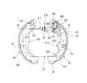
- the drum brake device 11 includes a first brake shoe 27 and a second brake shoe 29 that are a pair of brake shoes, a wheel cylinder 13, an anchor, and an anchor.
- the part 15, the adjuster 17, the cross-pull type spreading mechanism 19, the switching lever mechanism 21, and the switching strut 23 are configured as main members.
- the drum brake device 11 is integrally fixed to the vehicle body in such a posture that the backing plate 25 is substantially perpendicular to a rotation axis of a wheel (not shown).
- a pair of first brake shoes 27 and second brake shoes 29, each having a substantially arc shape are arranged vertically along the left and right outer peripheral edges.
- the first brake shoe 27 and the second brake shoe 29 are elastically supported by the first shoe hold device 31 and the second shoe hold device 33 so that the first web 35 and the second web 37 can move, and can be expanded. It has become.
- the first brake shoe 27 and the second brake shoe 29 are elastically urged in a direction approaching each other by a pair of first shoe return springs 39 and second shoe return springs 41.
- a wheel cylinder 13 as a fluid actuator is interposed between adjacent ends of the first brake shoe 27 and the second brake shoe 29 in the upper part of FIG.
- the wheel cylinder 13 is attached to the backing plate 25, and the first and second brake shoes 27 and 29 are expanded by pushing the first piston 43 and the second piston 45 in the direction away from each other. To do.
- the other adjacent ends of the first brake shoe 27 and the second brake shoe 29 in the lower part of FIG. 1 abut against a fixed anchor portion 15 attached to the backing plate 25.
- the first brake shoe 27 and the second brake shoe 29 are shown in FIG. 1 by the first piston 43 and the second piston 45 that are pressurized and operated from both ends thereof. Is expanded and rotated around the contact point with the anchor portion 15. As a result, the first brake shoe 27 and the second brake shoe 29 are frictionally engaged with an inner peripheral surface of a brake drum (not shown) to brake it.
- one of the first brake shoe 27 and the second brake shoe 29 is a leading shoe with respect to the rotation direction of the brake drum and has a self-servo property, and the other is a trailing shoe with respect to the rotation direction of the brake drum. Therefore, it does not have self-servo properties.
- the drum brake device 11 functions as a leading / trailing drum brake.
- the adjuster 17 includes an expansion mechanism 19 that expands each of the first brake shoe 27 and the second brake shoe 29 when an operating force is input to the backing plate 25 in the vertical direction via the parking cable 51. They are arranged in series.
- the adjuster 17 and the expansion mechanism 19 constitute a parking lever assembly 47 with an adjuster.
- the adjuster-equipped parking lever assembly 47 is disposed across one adjacent end of the first brake shoe 27 and the second brake shoe 29, and the parking lever 49 is moved in one direction.
- the pair of first brake shoes 27 and second brake shoes 29 are mechanically separated.
- a parking cable 51 is connected to the parking lever 49, and the parking cable 51 rotates the parking lever 49 in one direction in accordance with the operation force of the parking brake operation.
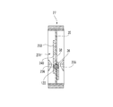
- the adjuster-attached parking lever assembly 47 includes an adjuster 17 and an expansion mechanism 19. Further, the adjuster 17 includes an adjuster lever 53 (see FIG. 1) and a strut 55. On the other hand, the expansion mechanism 19 includes a lever pin 57, a parking lever 49, and a bracket 59. The adjuster 17 is provided with a shoe gap automatic adjusting mechanism, and expands and contracts in the axial direction by an adjuster screw 61 (see FIG. 3).
- the adjuster lever 53 is pivotally supported by the first fulcrum pin 109 (see FIG. 1) so as to be able to rotate to the first web 35 of the first brake shoe 27.
- a first shoe return spring 39 is stretched between the adjuster lever 53 and the second brake shoe 29, and urges the adjuster lever 53 to rotate counterclockwise in FIG. Further, the arm portion 65 of the adjuster lever 53 is rotationally engaged with the toothed wheel 67 of the strut 55 by this rotation biasing force.
- the strut 55 has an adjuster socket 69 on one end side (left end side in FIG. 3) with the adjuster screw 61 interposed therebetween, and an engagement plate portion 71 on the other end side (right end side in FIG. 3).
- the adjuster socket 69 is in contact with the first web 35 of the first brake shoe 27.
- the engaging plate portion 71 engages with a concave contact portion 73 that is a rotating portion of the parking lever 49.
- the parking lever 49 has a pin engagement hole 75 through which the lever pin 57 serving as a rotation fulcrum is inserted above the concave contact portion 73.
- the parking lever 49 has a cable hooking portion 77 formed on the opposite side of the concave contact portion 73 (side driven by the parking cable 51).
- a lever pin 57 which is a rotation fulcrum of the parking lever 49 is arranged on the center side of the expansion mechanism (the center side in the left-right direction in FIG. 3).
- the side driven by the parking cable 51 of the parking lever 49 is arranged close to the second brake shoe 29 side.
- a bracket 59 in which one end 79 of the bracket holds the lever pin 57 that is the rotation fulcrum of the parking lever 49 and the other end 81 of the bracket abuts against the second brake shoe 29 is an insertion hole 83 that is a lead-out portion of the parking cable 51. It is slidably contacted to the backing plate 25 side on both sides of the side (see FIG. 3).
- the bracket 59 of the first embodiment has two plate portions 85 that sandwich the parking lever 49.
- An engaging recess 87 is formed in the bracket other end portion 81, and the engaging recess 87 abuts on the second web 37 of the second brake shoe 29.
- a protrusion 89 is formed on the side of the bracket one end 79 that holds the lever pin 57, and the protrusion 89 has a disengagement prevention mechanism that prevents the other end of the strut 55 from coming off from the concave contact portion 73 of the parking lever 49.
- An oval holding groove 91 that holds the lever pin 57 is formed above the protruding portion 89.
- the width of the bracket 59 on the side where the protruding portion 89 is formed is narrower than the outer diameter of the strut cylindrical portion 93. Accordingly, the strut cylindrical portion 93 is locked to the protruding portion 89 of the bracket 59, and the engagement plate portion 71 is prevented from being detached from the concave contact portion 73.
- the engagement plate portion 71 of the strut 55 is engaged with the concave contact portion 73.
- the parking lever 49 engaged with the strut 55 is inserted between the pair of plate portions 85 of the bracket 59.
- the parking lever 49 inserted into the bracket 59 is rotated around the lever pin 57 while the lever pin 57 is supported by the oval holding groove 91.
- a backing plate side contact portion 95 (see FIG. 3) is brought into contact with the backing plate 25 directly or via a contact member.
- the backing plate side contact portion 95 is brought into contact with the backing plate 25 via a lever plate 97 (see FIG. 3) that is a contact member.
- the backing plate 25 is provided with an insertion hole 83 (see FIG. 3) through which the parking cable 51 is inserted as a lead-out portion of the parking cable 51.
- the lever plate 97 is mounted on the wheel side surface of the backing plate 25 so as to overlap the insertion hole 83, and the lever plate 97 has a through hole 99 (see FIG. 3) that coincides with the insertion hole 83.
- a cable anchor 103 which is a parking cable anchor member, is disposed at the same center as the insertion hole 83.
- a cable case 105 is fixed to the tip of the cable anchor 103 at the same center, and the parking cable 51 led out from the cable case 105 passes through the insertion hole 83 and the through hole 99 and is hooked to the parking lever 49.
- a cable boot 107 (see FIG. 3) is fixed to the cable case 105 inside the cable anchor 103, and the parking cable 51 is inserted into the cable boot 107 inward.
- the cable anchor 103 fixed to the backing plate 25 is disposed between the backing plate 25 and the cable case 105. Since the parking cable 51 is pulled downward in FIG. 3, the cable case 105 inputs an upward force as a reaction force to the cable anchor 103 to the cable anchor 103. Accordingly, the cable acting force is received by the backing plate 25 in the thickness direction of the backing plate 25 and in the approaching direction facing each other with the cable anchor 103 interposed therebetween, and the cable anchor 103 can be advantageously configured in terms of attachment strength.
- a switching lever mechanism 21 is rotatably provided on a first brake shoe 27 that is one brake shoe.
- the switching lever mechanism 21 is rotated by an action force (expansion force) greater than or equal to a predetermined value of the expansion mechanism 19.
- a switching strut 23 is provided between adjacent ends of the first brake shoe 27 and the second brake shoe 29 on the anchor portion 15 side. The switching strut 23 expands against the urging force of the second shoe return spring 41 at the adjacent end of the first brake shoe 27 and the second brake shoe 29 on the anchor portion 15 side following the rotation of the switching lever mechanism 21. To do.
- the switching lever mechanism 21 is rotatable to one end side (wheel cylinder 13 side) of the first brake shoe 27 by the first fulcrum pin 109 as shown in FIGS. 5A and 5B.
- a first switching lever 111 that is supported and serves as an input side, and a second fulcrum pin 113 that is rotatably supported at a substantially middle portion of the first brake shoe 27 and that is a first output lever that rotates following the first switching lever 111.
- 2 switching lever 115 The first switching lever 111 receives an acting force from the expansion mechanism 19 between the sliding contact between the first switching lever 111 and the second switching lever 115 and the first fulcrum pin 109.
- the switching strut 23 that is driven by the rotation of the first switching lever 111 and the second switching lever 115 is the first.
- the distance between the fulcrum, the force point, and the action point is set so that the adjacent ends of the first brake shoe 27 and the second brake shoe 29 on the anchor portion 15 side are expanded against the urging force of the second shoe return spring 41. Has been.
- the adjuster socket 69 and the first switching lever 111 are in contact with each other at the first sliding contact 117, and the first switching lever 111 and the first switching lever 111 are in contact with each other.
- the second switching lever 115 is in contact with the second sliding contact 119, and the second switching lever 115 and the switching strut 23 are in contact with the third sliding contact 121.
- the distance is A
- the distance between the first fulcrum pin 109 and the second sliding contact 119 along the virtual center line 123 is B
- the distance between the second fulcrum pin 113 and the third sliding contact 121 in the direction along the virtual center line 123 is D. Therefore, each distance is set to 1 ⁇ (A / B) ⁇ (C / D) ⁇ 3.
- the wheel cylinder 13 side of the first brake shoe 27 and the second brake shoe 29 is first expanded by the input from the expansion mechanism 19 and comes into contact with the inner peripheral surface of the brake drum.
- the reaction force from the inner peripheral surface acts on the first brake shoe 27 and the second brake shoe 29, so that the acting force (expanding force) of the expanding mechanism 19 is not less than a predetermined value.
- the first switching lever 111 and the second switching lever 115 are configured to rotate and transmit the acting force to the switching strut 23.
- the operation of the drum brake device 11 having the above configuration will be described.
- the parking cable 51 is pulled according to the operation of an operation member (such as an operation lever) in the vehicle interior from the state before the parking operation
- the parking with the adjuster is performed in the initial operation.
- the adjacent ends of the first brake shoe 27 and the second brake shoe 29 on the wheel cylinder 13 side are first expanded by the lever assembly 47, and the positions of the first brake shoe 27 and the second brake shoe 29 are determined.
- the acting force (expanding force) of the spreading mechanism 19 acts on the first brake shoe 27 and the second brake shoe 29 and exceeds a predetermined value
- the first switching lever 111 rotates and the first switching lever 111 performs the second switching.
- the lever 115 is pressed. Therefore, the second switching lever 115 rotates about the second fulcrum pin 113 counterclockwise in FIG.
- the second switching lever 115 presses the second brake shoe 29 via the switching strut 23.
- the adjacent ends of the first brake shoe 27 and the second brake shoe 29 on the anchor portion 15 side are expanded and pressed against the inner peripheral surface of the brake drum.
- the switching lever mechanism 21 including the first switching lever 111 and the second switching lever 115 provided for mode switching does not rotate, and the mode switching mechanism It does not work. Therefore, the switching lever mechanism is provided after the adjacent ends of the first brake shoe 27 and the second brake shoe 29 on the wheel cylinder 13 side are expanded and abutted against the inner peripheral surface of the brake drum by the acting force of the expansion mechanism 19. 21, the adjacent ends of the first brake shoe 27 and the second brake shoe 29 on the anchor portion 15 side are expanded and contact the inner peripheral surface of the brake drum. Therefore, the adhesion between the first brake shoe 27 and the second brake shoe 29 and the drum sliding surface is improved.
- the first brake shoe 27 and the second brake shoe 29 are expanded on both the wheel cylinder 13 side and the anchor portion 15 side, and the drum slide Adhesion to the moving surface is improved.
- a high parking braking force as a duo servo is obtained, and loosening that occurs when the parking braking force is generated is prevented.
- the first to third sliding contacts 117, 119, 121 are transmitted in the transmission of the acting force.
- the amount of displacement is reduced. For this reason, problems such as wear are unlikely to occur.
- the positions of the first fulcrum pin 109 and the second fulcrum pin 113, and the first to the second switching levers 115 abut on each other.
- first switching lever 111 and the second switching lever 115 the positions of the first fulcrum pin 109 and the second fulcrum pin 113 and the lengths of the first switching lever 111 and the second switching lever 115 are appropriately set. And the degree of freedom of layout in the brake drum of the switching lever mechanism 21 is high.
- the drum brake device 11 is disposed on the back side surface 101 of the backing plate 25 and has a motor gear unit 125 as a drive mechanism that pulls and drives the parking cable 51 connected to the expansion mechanism 19.
- a drum brake device including an electric parking brake can be obtained.
- the expansion mechanism 19 can be operated electrically. As described above, high efficiency (power saving) is realized because the duo-servo drum brake is used during parking brake.
- a dual mode brake structure that functions as a leading / trailing type at the time of service brake and a duo servo type at the time of parking brake can be configured at low cost. Further, according to the drum brake device 11 according to the present embodiment, the parking brake can be easily electrified.
- the drum brake device 210 according to the second embodiment is provided with a dual mode brake structure, like the drum brake device 11 according to the first embodiment.
- symbol is attached
- the drum brake device 210 of the second embodiment uses a forward-pull type expansion mechanism 219 instead of the cross-pull type expansion mechanism 19 used in the drum brake device 11 shown in the first embodiment.
- the adjuster 217 is arranged in series.
- the adjuster 217 and the expansion mechanism 219 constitute a parking lever assembly 247 with an adjuster.
- the adjuster-equipped parking lever assembly 247 is disposed across one adjacent end of the first brake shoe 27 and the second brake shoe 29, and the parking brake lever 201. Is rotated in one direction to mechanically separate the first brake shoe 27 and the second brake shoe 29 from each other.
- the parking brake lever 201 is pivotally supported by the second web 37 on the end side near the wheel cylinder 13 of the second brake shoe 29 via a pin 127 so as to be rotatable in a plane perpendicular to the drum axis.
- a parking brake cable (not shown) is connected to the free end 203 of the parking brake lever 201, and the free end 203 of the parking brake lever 201 is moved in the direction indicated by W by pulling the parking brake cable with the parking brake operating force. Displaced.
- the parking brake lever 201 on the one hand, the second brake shoe 29 expands around the contact point with the anchor portion 15 via the pin 127, and on the other hand, the first brake shoe 27 moves to the anchor portion 15 via the adjuster 217.
- the forward pull type expansion mechanism 219 is configured to expand around the contact point.
- the adjuster 217 includes an adjuster lever 53 and a strut 255 and includes an automatic shoe clearance adjustment mechanism, and is extended and contracted in the axial direction by an adjuster screw 61 (see FIG. 10).
- the strut 255 has an adjuster socket 269 on one end side (right end side in FIG. 10) with the adjuster screw 61 interposed therebetween, and is engaged with the first web 35 of the first brake shoe 27. Further, the other end portion side (the left end side in FIG. 10) of the strut 255 sandwiching the adjuster screw 61 is an engagement plate portion 271, and is engaged with the second web 37 of the second brake shoe 29.
- a switching lever mechanism 213 is rotatably provided on the first brake shoe 27 which is one of the brake shoes, and the switching lever mechanism 213 is an expansion mechanism. 219 is rotated by an action force (expansion force) exceeding a predetermined value.
- a switching strut 23 is provided between adjacent ends of the first brake shoe 27 and the second brake shoe 29 on the anchor portion 15 side. The switching strut 23 expands against the urging force of the second shoe return spring 41 at the adjacent end of the first brake shoe 27 and the second brake shoe 29 on the anchor portion 15 side following the rotation of the switching lever mechanism 213. To do.
- the switching lever mechanism 213 is rotatable to one end side (wheel cylinder 13 side) of the first brake shoe 27 by the first fulcrum pin 109.
- a first switching lever 211 that is supported and serves as an input side, and a second fulcrum pin 113 that is rotatably supported at a substantially middle portion of the first brake shoe 27 and that is an output side that rotates following the first switching lever 211.
- the first switching lever 211 receives an acting force from the expansion mechanism 219 between the sliding contact between the first switching lever 211 and the second switching lever 215 and the first fulcrum pin 109.
- the switching strut 23 that is driven by the rotation of the first switching lever 211 and the second switching lever 215 is the first.
- the distance between the fulcrum, the force point, and the action point is such that the adjacent ends of the first brake shoe 27 and the second brake shoe 29 on the anchor portion 15 side are expanded against the urging force of the second shoe return spring 41. Is set.
- the adjuster socket 269 and the first switching lever 211 are in contact with each other at the first sliding contact 227, and the first switching lever 211 and the first switching lever 211 are in contact with each other.
- the second switching lever 215 is in contact with the second sliding contact 229, and the second switching lever 215 and the switching strut 23 are in contact with the third sliding contact 221.
- the side end 215a that contacts the first switching lever 211 is along the back side surface of the first web 35, and the side end 215b that contacts the switching strut 23 is the first.
- the web 35 is bent along the front side surface and attached so as to sandwich the first web 35 (see FIG. 11).
- the wheel cylinder 13 side of the first brake shoe 27 and the second brake shoe 29 is first expanded by the input from the expansion mechanism 219, and the inner peripheral surface of the brake drum. After the positions of the first brake shoe 27 and the second brake shoe 29 are determined, the reaction force from the inner peripheral surface acts on the first brake shoe 27 and the second brake shoe 29 to expand the expansion mechanism 219.
- the first switching lever 211 and the second switching lever 215 are rotated so that the acting force is transmitted to the switching strut 23 when the acting force (expansion force) becomes equal to or greater than a predetermined value.
- the second switching lever 215 includes a side end 215 a that contacts the first switching lever 211 and a side end 215 b that contacts the switching strut 23. 35 is formed so as to be located on opposite sides of each other. Therefore, as shown in FIG. 6, when the adjuster 217 is disposed on the opposite side of the backing plate 25 with the first web 35 interposed therebetween, the anchor brake unit 201 operates the parking brake lever 201 that operates the expansion mechanism 219. In order to avoid interference with the connected parking brake cable, the side end 215 b of the second switching lever that contacts the switching strut 23 is disposed on the side opposite to the backing plate 25.
- the first switching lever 211 is disposed on the backing plate 25 side, and the side end 215a of the second switching lever 215 that contacts the first switching lever 211 is provided. , Arranged on the backing plate 25 side. Therefore, the first switching lever 211 and the second switching lever 215 can be easily attached to the first web 35.
- the second switching lever 215 has a pair of sandwiching portions 218 that are bent so as to sandwich the first web 35, and the through holes 216 of the pair of sandwiching portions 218 and the second
- the first web 35 is rotatably supported by a second fulcrum pin 113 inserted into the support hole 36 of the first web 35.
- the second fulcrum pin 113 that penetrates the pair of sandwiching portions 218 is prevented from coming off by the C clip 116 at the penetrating end. Therefore, the second switching lever 215 is rotatably supported by a pair of sandwiching portions 218 that are respectively located on the front and back side surfaces of the first web 35. Therefore, when the second switching lever 215 is rotated, an uneven load is not applied to the first web 35, and a smooth rotation operation is possible.
- a switching lever mechanism 231 that is rotatably provided on the first brake shoe 27 and is rotated by an action force greater than or equal to a predetermined value of the expansion mechanism 219 includes a first switching lever 211, a first switching lever 211, and a first switching lever 211. And a second switching lever 233 on the output side that is rotatably supported by the two fulcrum pins 122 at a substantially middle portion of the first brake shoe 27 and is rotated by the first switching lever 211.
- the second switching lever 233 is formed so that a side end 233a that contacts the first switching lever 211 and a side end 233b that contacts the switching strut 23 are located on opposite sides of the first web 35. . Therefore, similarly to the switching lever mechanism 213, the first switching lever 211 and the second switching lever 233 constituting the switching lever mechanism 231 can be easily attached to the first web 35.
- the second switching lever 233 has a pair of sandwiching portions 238 that are bent so as to sandwich the first web 35, and the notch holes 235 and 236 of the pair of sandwiching portions 238 and the first web 35.
- a second fulcrum pin 122 inserted into the support hole 36 is rotatably supported by the first web 35. Therefore, as with the switching lever mechanism 213, the second switching lever 233 can be smoothly rotated without applying an uneven load to the first web 35 when the second switching lever 233 is rotated. It becomes.
- the second fulcrum pin 122 is a stepped pin whose both ends are small diameter portions 122b with respect to the central large diameter portion 122a.
- the large diameter portion 122 a has an outer diameter substantially equal to the inner diameter of the support hole 36 and an axial width substantially equal to the plate thickness of the first web 35.
- the small diameter portion 122b has an outer diameter substantially equal to the opening width of the cutout holes 235 and 236.
- the large diameter portion 122 a of the second fulcrum pin 122 is fitted into the support hole 36.
- the pair of sandwiching portions 238 is inserted into the first web such that the small diameter portions 122b projecting from the support holes 36 to the front and back sides of the first web 35 are inserted from the notch opening end sides of the notches 235 and 236, respectively. Attach to 35.
- the second switching lever 233 attached to the first web 35 is configured such that the shaft portion of the second shoe hold device 33 that passes through the through hole 38 of the first web 35 is loosely fitted into the through hole 240, thereby
- the second fulcrum pin 122 is rotatably supported in a state in which movement relative to 35 is restricted. At this time, the second fulcrum pin 122 is prevented from coming off by locking the axial step of the large diameter portion 122a to the inner edge of the notches 235 and 236. Need not be used (see FIG. 14).
- the operation of the drum brake device 210 having the above configuration will be described.
- the parking lever assembly with an adjuster is initially set in the operation.
- the adjacent ends of the first brake shoe 27 and the second brake shoe 29 on the wheel cylinder 13 side are first expanded by the solid 247, and the positions of the first brake shoe 27 and the second brake shoe 29 are determined.
- the acting force (expanding force) of the expansion mechanism 219 acts on the first brake shoe 27 and the second brake shoe 29 and exceeds a predetermined value
- the first switching lever 211 rotates and the first switching lever 211 performs the second switching.
- the lever 215 (233) is pressed. Therefore, the second switching lever 215 (233) rotates around the second fulcrum pin 113 (122) clockwise in FIG.
- the second switching lever 215 (233) presses the second brake shoe 29 via the switching strut 23.
- the adjacent ends of the first brake shoe 27 and the second brake shoe 29 on the anchor portion 15 side are expanded and pressed against the inner peripheral surface of the brake drum.
- the forward pull type expansion mechanism 219 for parking brake is used.
- the switching lever mechanism 213 (231) including the first switching lever 211 and the second switching lever 215 (233) arranged for mode switching rotates. And the mode switching mechanism does not operate. Therefore, the switching lever mechanism is provided after the adjacent ends of the first brake shoe 27 and the second brake shoe 29 on the wheel cylinder 13 side are expanded by the acting force of the expansion mechanism 219 and contact the inner peripheral surface of the brake drum.
- first brake shoe 27 and the second brake shoe 29 on the anchor portion 15 side are expanded by 213 (231) and come into contact with the inner peripheral surface of the brake drum, the first brake shoe 27 and the second brake shoe Adhesion between 29 and the drum sliding surface is improved.
- the drum brake device 210 of the second embodiment at the end of the parking operation, the first brake shoe 27 and the second brake shoe 29 are expanded both on the wheel cylinder 13 side and the anchor portion 15 side, and the drum slide Adhesion to the moving surface is improved.
- the parking brake is operated, a high parking braking force as a duo servo is obtained, and loosening that occurs when the parking braking force is generated is prevented.
- the drum brake device adds a mode switching mechanism regardless of the configuration difference between the cross-pull type spreading mechanism 19 and the forward-pull type spreading mechanism 219 having different parking cable pulling directions. be able to. Further, the cable attachment portion of the backing plate 25 can be provided at a general position, and the cost of the backing plate 25 can be prevented from being significantly increased without complicating the shape of the backing plate as in the prior art.
- a pair of brake shoes (first brake shoe and second brake shoe) 27 and 29 which are arranged so as to face the inner peripheral surface of the brake drum and are elastically supported so as to be movable on the backing plate 25, and the pair of brake shoes
- the brake shoes (first brake shoe and second brake shoe) 27 and 29 are interposed between adjacent ends, and the pair of brake shoes (first brake shoe and second brake shoe) 27 and 29 are expanded.
- the pair of brake shoes (the first brake shoe and the first brake shoe) in the vicinity of the wheel cylinder 13 2 brake shoes) 27 and 29, which are interposed between the adjacent ends of the brake shoes 27 and 29, are arranged in series with the adjuster 17 for adjusting the shoe interval, and the pair of brake shoes ( (First brake shoe and second brake shoe) 27, 29, and an expansion mechanism 19 that expands each, and one brake shoe (first brake shoe) 27 is rotatably provided.
- the switching lever mechanism 21 rotated by the above acting force and the pair of brake shoes (first brake shoe and second brake shoe) 27, 29 are provided between adjacent ends on the anchor portion side, and the switching lever mechanism 21
- the adjacent ends of the pair of brake shoes (first brake shoe and second brake shoe) 27, 29 on the anchor portion 15 side following the rotation of Drum brake device 11 includes a switching strut 23, the to expansion.
- the switching lever mechanism 213 is rotatably supported on the one brake shoe (first brake shoe) 27 by the first fulcrum pin 109 and input.
- the first switching lever 211 on the side and the second fulcrum pin 113 are rotatably supported by the one brake shoe (first brake shoe) 27 and become the output side that rotates following the first switching lever 211.
- a second switching lever 215, and the first switching lever 211 includes a sliding contact (second sliding contact) 229 between the first switching lever 211 and the second switching lever 215 and the first fulcrum pin 109.
- a drum brake device 210 that receives an acting force from the expansion mechanism 219. [3] In the drum brake device 210 configured as described in [2] above, the second switching lever 215 is bent so as to sandwich the first web 35 of the one brake shoe (first brake shoe) 27.
- a drum brake device 210 having a pair of sandwiched portions 218 that are rotatably supported by the first web 35.
- the second switching lever 215 includes a side end 233a that contacts the first switching lever 211 and a side end 233b that contacts the switching strut 23.
- the drum brake device 210 is formed by bending so that the first web 35 of the one brake shoe (first brake shoe) 27 is located on the opposite side of the first web 35.
- the drum brake devices 11 and 210 are provided with a drive mechanism (motor gear unit) 125 for pulling and driving.
- the drum brake device of the present invention is not limited to the above-described embodiment, and can be appropriately modified and improved.
- the material, shape, dimensions, number, arrangement location, and the like of each component in the above-described embodiment are arbitrary and are not limited as long as the present invention can be achieved.
- This application is based on a Japanese patent application filed on July 25, 2012 (Japanese Patent Application No. 2012-165005) and a Japanese patent application filed on May 17, 2013 (Japanese Patent Application No. 2013-105237). The contents are incorporated herein by reference.
- the dual mode brake structure that functions as a leading / trailing type at the time of service brake and a duo-servo type at the time of parking brake allows the service to be performed without causing a drag phenomenon due to running vibration during running.
- the braking force during braking can be stabilized.
Abstract
A drum brake device (11) is provided with first and second brake shoes (27, 29), a wheel cylinder (13), an anchor section (15), an adjuster (17), an expansion mechanism (19) which expands the first brake shoe (27) and the second brake shoe (29), a switching lever mechanism (21) which is rotated by the operating force of the expansion mechanism (19) which is greater than or equal to a predetermined level, and a switching strut (23) which follows the rotation of the switching lever mechanism (21) and expands adjacent ends of the first and second brake shoes (27, 29), the adjacent ends facing the anchor section (15).
Description
本発明は、ドラムブレーキ装置に関する。
The present invention relates to a drum brake device.
油圧シリンダ装置の作動によるサービスブレーキ時はリーディング・トレーリング(LT)式のドラムブレーキ装置として作動し、パーキングブレーキレバーの操作によるパーキングブレーキ時はデュオサーボ(DS)式のドラムブレーキ装置として作動するデュアルモード構造を備えたドラムブレーキ装置が知られている(特許文献1参照)。
Dual acting as a leading / trailing (LT) type drum brake device during service braking by hydraulic cylinder device operation and as a duo-servo (DS) type drum brake device during parking brake operation by operating the parking brake lever A drum brake device having a mode structure is known (see Patent Document 1).
図15に示すこの種のデュアルモードドラムブレーキ装置501には、図示しないブレーキドラムの内周面に対向するよう配置された一対の第1シュー503及び第2シュー505が設けられている。これら第1シュー503及び第2シュー505は、第1シューホールド装置507及び第2シューホールド装置509によりバッキングプレート511に制限範囲内で相対移動可能に弾性支持されている。また、第1シュー503及び第2シュー505は、一対の第1シューリターンスプリング513及び第2シューリターンスプリング515により相互に接近する方向に弾性付勢されている。図15の下方における第1シュー503及び第2シュー505の隣接端は、それぞれバッキングプレート511に取り付け固定されたアンカ517に当接している。図15の上方における第1シュー503及び第2シュー505の隣接端は、それぞれバッキングプレート511に取り付けた流体式アクチュエータとしてのホイールシリンダ519の第1ピストン521及び第2ピストン523により押動可能とされており、これらにより第1シュー503と第2シュー505とが拡開するように構成されている。
15 is provided with a pair of first shoes 503 and a second shoe 505 arranged to face an inner peripheral surface of a brake drum (not shown). The first shoe 503 and the second shoe 505 are elastically supported on the backing plate 511 by the first shoe hold device 507 and the second shoe hold device 509 so as to be relatively movable within a limited range. Further, the first shoe 503 and the second shoe 505 are elastically biased in a direction approaching each other by a pair of the first shoe return spring 513 and the second shoe return spring 515. The adjacent ends of the first shoe 503 and the second shoe 505 in the lower part of FIG. 15 are in contact with anchors 517 attached and fixed to the backing plate 511. The adjacent ends of the first shoe 503 and the second shoe 505 in the upper part of FIG. 15 can be pushed by the first piston 521 and the second piston 523 of the wheel cylinder 519 as a fluid actuator attached to the backing plate 511, respectively. Thus, the first shoe 503 and the second shoe 505 are configured to expand.
第2シュー505には、ホイールシリンダ519に近い端部側において第2ウエブ525にピン527を介しフォワードプル型の第1パーキングブレーキレバー529が枢支されている。当該機械式アクチュエータ(拡開機構)を構成する第1パーキングブレーキレバー529は、ドラム軸直角面内で回動可能とされている。第1パーキングブレーキレバー529の遊端531には、図示しないパーキングブレーキケーブルが接続されている。このパーキングブレーキケーブルがパーキングブレーキ操作力により牽引されることにより、第1パーキングブレーキレバー529の遊端531がWで示す方向へ変位する。これにより、第1パーキングブレーキレバー529が、ピン527の周りで対応方向へ回動されるように構成されている。
A forward pull type first parking brake lever 529 is pivotally supported on the second shoe 505 via a pin 527 on the second web 525 on the end side close to the wheel cylinder 519. The first parking brake lever 529 constituting the mechanical actuator (expansion mechanism) is rotatable in a plane perpendicular to the drum axis. A parking brake cable (not shown) is connected to the free end 531 of the first parking brake lever 529. When the parking brake cable is pulled by the parking brake operating force, the free end 531 of the first parking brake lever 529 is displaced in the direction indicated by W. Accordingly, the first parking brake lever 529 is configured to rotate around the pin 527 in the corresponding direction.
この第1パーキングブレーキレバー529は、一方でピン527を介して第2シュー505をアンカ517との当接点周りに拡開し、他方でストラット533を介し第2パーキングブレーキレバー535を突起537の周りで時計回り方向へ回動するために、該突起537を介して第1シュー503をアンカ517との当接点周りに拡開するための拡開機構を構成している。
The first parking brake lever 529 expands the second shoe 505 around the contact point with the anchor 517 on the one hand via the pin 527 and on the other hand moves the second parking brake lever 535 around the protrusion 537 via the strut 533. In order to rotate in the clockwise direction, an expansion mechanism for expanding the first shoe 503 around the contact point with the anchor 517 via the projection 537 is configured.
ドラム回転方向後方側の第1シュー503及び第2シュー505の端部がブレーキドラムに連れ回され、ドラム回転力がストラット533を介し第1シュー503及び第2シュー505に伝達されてアンカ517で受け止められることにより、上記デュアルモードドラムブレーキ装置501は、パーキングブレーキ時にデュオサーボ式のドラムブレーキとなる。
Ends of the first shoe 503 and the second shoe 505 on the rear side in the drum rotation direction are rotated by the brake drum, and the drum rotational force is transmitted to the first shoe 503 and the second shoe 505 via the strut 533 and is received by the anchor 517. By being received, the dual mode drum brake device 501 becomes a duo-servo type drum brake during parking brake.
ところで、上述のデュアルモードドラムブレーキ装置501では、パーキングブレーキ時にデュオサーボ式のドラムブレーキとなるために、拡開機構を構成する第1パーキングブレーキレバー529が、一方でピン527を介して第2シュー505をアンカ517との当接点周りに拡開し、他方でストラット533を介し第2パーキングブレーキレバー535を回動するために、突起537を介して第1シュー503をアンカ517との当接点周りに拡開する。そこで、第1パーキングブレーキレバー529に押圧されたストラット533は、第2パーキングブレーキレバー535を押圧する。ところが、この時、第1シュー503は、第2パーキングブレーキレバー535と回動中心となる突起537とに回動可能に嵌合していることから、アンカ517に当接するためには第1シューリターンスプリング513の荷重が、第2シューリターンスプリング515の荷重より大きい必要がある。従って、第1シュー503と第2シュー505のアンカ517への当接力が大きくなってしまう。その為、サービスブレーキ時に制動力の安定化を図るため、図中下方における第1シュー503及び第2シュー505の隣接端が当接するアンカ517に傾きを設けた場合には、走行時の振動等で第2シュー505及び第1シュー503がホイールシリンダ519側へ移動して引きずりを発生する虞がある。
By the way, in the above-described dual mode drum brake device 501, the first parking brake lever 529 constituting the expansion mechanism is provided with the second shoe via the pin 527 in order to become a duo-servo type drum brake at the time of parking brake. 505 is expanded around the contact point with the anchor 517 and, on the other hand, the first shoe 503 is moved around the contact point with the anchor 517 via the protrusion 537 in order to rotate the second parking brake lever 535 via the strut 533. To expand. Therefore, the strut 533 pressed by the first parking brake lever 529 presses the second parking brake lever 535. However, at this time, since the first shoe 503 is rotatably fitted to the second parking brake lever 535 and the protrusion 537 serving as the rotation center, the first shoe 503 is in contact with the anchor 517. The load of the return spring 513 needs to be larger than the load of the second shoe return spring 515. Therefore, the contact force of the first shoe 503 and the second shoe 505 to the anchor 517 is increased. Therefore, in order to stabilize the braking force at the time of service braking, when an anchor 517 with which the adjacent ends of the first shoe 503 and the second shoe 505 are in contact with each other in the lower part of the drawing is provided with an inclination during running, etc. Therefore, there is a possibility that the second shoe 505 and the first shoe 503 move toward the wheel cylinder 519 to cause dragging.
本発明は上記状況に鑑みてなされたもので、その目的は、デュアルモードブレーキ構造におけるパーキング制動力の安定性を高めることができるドラムブレーキ装置を提供することにある。
The present invention has been made in view of the above situation, and an object of the present invention is to provide a drum brake device capable of enhancing the stability of the parking braking force in the dual mode brake structure.
本発明に係る上記目的は、下記構成により達成される。
(1) ブレーキドラムの内周面に対向するよう配置されてバッキングプレートに移動可能に弾性支持される一対のブレーキシューと、前記一対のブレーキシューの一方の隣接端間に介装され、前記一対のブレーキシューのそれぞれを拡開するためのホイールシリンダと、前記バッキングプレートに固定され、前記一対のブレーキシューの他方の隣接端が当接するアンカ部と、前記ホイールシリンダの近傍における前記一対のブレーキシューの一方の隣接端間に介装され、シュー間隔を調整するアジャスタと、前記アジャスタと直列に配置され、操作力が入力されることで前記一対のブレーキシューのそれぞれを拡開する拡開機構と、一方のブレーキシューに回転自在に設けられ、前記拡開機構の所定以上の作用力により回転される切替レバー機構と、前記一対のブレーキシューのアンカ部側の隣接端間に設けられ、前記切替レバー機構の回転に従動して前記一対のブレーキシューのアンカ部側の隣接端を拡開する切替ストラットと、を備えるドラムブレーキ装置。 The above object of the present invention is achieved by the following configuration.
(1) A pair of brake shoes disposed so as to oppose the inner peripheral surface of the brake drum and elastically supported so as to be movable on a backing plate, and interposed between one adjacent ends of the pair of brake shoes, A wheel cylinder for expanding each of the brake shoes, an anchor portion fixed to the backing plate and in contact with the other adjacent end of the pair of brake shoes, and the pair of brake shoes in the vicinity of the wheel cylinder An adjuster for adjusting a shoe interval, and an expansion mechanism that is arranged in series with the adjuster and that expands each of the pair of brake shoes by inputting an operation force. A switching lever that is rotatably provided on one brake shoe and is rotated by an action force that is greater than or equal to a predetermined value of the expansion mechanism. A switching strut provided between a mechanism and an adjacent end on the anchor portion side of the pair of brake shoes, and expanding an adjacent end on the anchor portion side of the pair of brake shoes in accordance with the rotation of the switching lever mechanism; A drum brake device comprising:
上記(1)の構成のドラムブレーキ装置によれば、パーキングブレーキ作動時に、拡開機構からの入力によりアジャスタを介して一対のブレーキシューの一方の隣接端が拡開される。拡開された一対のブレーキシューの一方の隣接端がブレーキドラムの内周面に当接し、内周面からの反力が一対のブレーキシューに作用して拡開機構の作用力(拡開力)が所定以上となると、切替レバー機構が切替ストラットを介して一対のブレーキシューのアンカ部側の隣接端を拡開し、一対のブレーキシューがブレーキドラムの内周面に押圧される。
即ち、アジャスタ設置部位側のブレーキシューにブレーキドラムの内周面からの反力が作用するまでは、パーキングブレーキのためのブレーキシューの拡開動作によってはモード切替のために配設した切替レバー機構が回転せず、モード切替機構が作動しない構成である。そこで、拡開機構の作用力により、一対のブレーキシューの一方の隣接端が拡開されてブレーキドラムの内周面に当接した後、切替レバー機構により一対のブレーキシューのアンカ部側の隣接端が拡開されてブレーキドラムの内周面に当接するため、一対のブレーキシューとドラム摺動面との密着性が向上する。
従って、パーキング操作終了時、一対のブレーキシューは、ホイールシリンダ側とアンカ部側の双方で開拡され、ドラム摺動面に対する密着性が向上する。その結果、パーキングブレーキ作動時には、デュオサーボとしての高いパーキング制動力が得られると共に、パーキング制動力が生じる時に発生する緩みが防止される。 According to the drum brake device having the above configuration (1), when the parking brake is operated, one adjacent end of the pair of brake shoes is expanded through the adjuster by an input from the expansion mechanism. One adjacent end of the pair of expanded brake shoes comes into contact with the inner peripheral surface of the brake drum, and a reaction force from the inner peripheral surface acts on the pair of brake shoes to exert an acting force of the expansion mechanism (expanding force). ) Exceeds a predetermined value, the switching lever mechanism expands the adjacent ends on the anchor portion side of the pair of brake shoes via the switching struts, and the pair of brake shoes is pressed against the inner peripheral surface of the brake drum.
In other words, until the reaction force from the inner peripheral surface of the brake drum acts on the brake shoe on the adjuster installation site side, the switching lever mechanism arranged for switching the mode depending on the operation of expanding the brake shoe for parking brake Does not rotate and the mode switching mechanism does not operate. Therefore, after the one of the adjacent ends of the pair of brake shoes is expanded and brought into contact with the inner peripheral surface of the brake drum by the acting force of the expanding mechanism, the switching lever mechanism is adjacent to the anchor portion side of the pair of brake shoes. Since the end is expanded and contacts the inner peripheral surface of the brake drum, the adhesion between the pair of brake shoes and the drum sliding surface is improved.
Accordingly, at the end of the parking operation, the pair of brake shoes are expanded on both the wheel cylinder side and the anchor portion side, and the adhesion to the drum sliding surface is improved. As a result, when the parking brake is operated, a high parking braking force as a duo servo is obtained, and loosening that occurs when the parking braking force is generated is prevented.
(2) 上記(1)の構成のドラムブレーキ装置であって、前記切替レバー機構は、前記一方のブレーキシューの第1ウエブを挟持するように折り曲げ形成された一対の挟持部を有し、これら一対の挟持部が前記第1ウエブに回転自在に支持されるドラムブレーキ装置。
(2) The drum brake device having the above-described configuration (1), wherein the switching lever mechanism includes a pair of sandwiching portions formed to bend so as to sandwich the first web of the one brake shoe. A drum brake device in which a pair of clamping portions are rotatably supported by the first web.
上記(2)の構成のドラムブレーキ装置によれば、切替レバー機構は、第1ウエブの表裏側面にそれぞれ位置する一対の挟持部が回転自在に支持される。そこで、切替レバー機構が回転された時に第1ウエブに対して偏荷重が作用することがなく、円滑な回転動作が可能となる。
According to the drum brake device having the above-described configuration (2), the switching lever mechanism is rotatably supported by the pair of clamping portions respectively positioned on the front and back side surfaces of the first web. Therefore, when the switching lever mechanism is rotated, an uneven load is not applied to the first web, and a smooth rotation operation is possible.
(3) 上記(1)の構成のドラムブレーキ装置であって、前記切替レバー機構は、前記拡開機構に係合する側端と前記切替ストラットに係合する側端とが、前記一方のブレーキシューにおける第1ウエブを挟んで互いに反対側に位置するように折り曲げ形成されるドラムブレーキ装置。
(3) The drum brake device having the above-described configuration (1), wherein the switching lever mechanism includes a side end that engages with the expansion mechanism and a side end that engages with the switching strut. A drum brake device formed by bending so as to be positioned on opposite sides of a first web in a shoe.
上記(3)の構成のドラムブレーキ装置によれば、アジャスタが第1ウエブを挟んでバッキングプレートと反対側に配置されている場合、アンカ部側では拡開機構を操作するパーキングブレーキケーブル等との干渉を避けるために切替ストラットに係合する切替レバー機構の側端が、バッキングプレートと反対側に配置される。また、ホイールシリンダ側ではアジャスタとの干渉を避けるために拡開機構に係合する側端が、バッキングプレート側に配置される。そこで、切替レバー機構は第1ウエブに容易に装着することができる。
According to the drum brake device having the above configuration (3), when the adjuster is disposed on the opposite side of the backing plate with the first web interposed therebetween, the anchor portion is connected to the parking brake cable or the like for operating the expansion mechanism. The side end of the switching lever mechanism that engages with the switching strut to avoid interference is disposed on the side opposite to the backing plate. On the wheel cylinder side, a side end that engages with the expansion mechanism is disposed on the backing plate side in order to avoid interference with the adjuster. Therefore, the switching lever mechanism can be easily attached to the first web.
(4) 上記(1)の構成のドラムブレーキ装置であって、前記切替レバー機構が、第1支点ピンによって前記一方のブレーキシューに回転自在に支持され入力側となる第1切替レバーと、第2支点ピンによって前記一方のブレーキシューに回転自在に支持され前記第1切替レバーに従動して回転する出力側となる第2切替レバーと、を有し、前記第1切替レバーが、前記第1切替レバーと前記第2切替レバーとの摺接点と前記第1支点ピンとの間で、前記拡開機構からの作用力を受けるドラムブレーキ装置。
(4) The drum brake device having the above-described configuration (1), wherein the switching lever mechanism is rotatably supported on the one brake shoe by a first fulcrum pin and serves as an input side; A second switching lever that is rotatably supported by the one brake shoe by two fulcrum pins and that is an output side that rotates following the first switching lever, and the first switching lever includes the first switching lever. A drum brake device that receives an acting force from the expansion mechanism between a sliding contact between the switching lever and the second switching lever and the first fulcrum pin.
上記(4)の構成のドラムブレーキ装置によれば、モード切替えのために設置された切替レバー機構を構成する第1切替レバー及び第2切替レバーでは、作用力の伝達において、それぞれの摺接点の変位量が少なくなる。このため、摩滅等の問題が起こり難い。また、第1切替レバー及び第2切替レバーでは、第1支点ピン及び第2支点ピンの位置や、第1切替レバーと第2切替レバーとが互いに当接する摺接点位置を設定することで、第1及び第2切替レバーの適正な伝達比を容易に選定することができ、一対のブレーキシューとドラム摺動面との最適な密着性が得やすくなる。更に、第1切替レバー及び第2切替レバーでは、第1支点ピン及び第2支点ピンの位置や各レバーの長さを適宜設定することができ、切替レバー機構のブレーキドラム内におけるレイアウトの自由度が高い。
According to the drum brake device having the above configuration (4), in the first switching lever and the second switching lever constituting the switching lever mechanism installed for mode switching, in the transmission of the acting force, each sliding contact The amount of displacement decreases. For this reason, problems such as wear are unlikely to occur. In the first switching lever and the second switching lever, the positions of the first fulcrum pin and the second fulcrum pin and the sliding contact positions where the first switching lever and the second switching lever abut each other are set. Appropriate transmission ratios of the first and second switching levers can be easily selected, and optimal adhesion between the pair of brake shoes and the drum sliding surface can be easily obtained. Further, in the first switching lever and the second switching lever, the position of the first fulcrum pin and the second fulcrum pin and the length of each lever can be set as appropriate, and the degree of freedom of layout in the brake drum of the switching lever mechanism Is expensive.
(5) 上記(4)の構成のドラムブレーキ装置であって、前記第2切替レバーは、前記一方のブレーキシューの第1ウエブを挟持するように折り曲げ形成された一対の挟持部を有し、これら一対の挟持部が前記第1ウエブに回転自在に支持されるドラムブレーキ装置。
(5) In the drum brake device configured as described in (4) above, the second switching lever has a pair of sandwiching portions formed to bend so as to sandwich the first web of the one brake shoe, A drum brake device in which the pair of clamping portions are rotatably supported by the first web.
上記(5)の構成のドラムブレーキ装置によれば、第2切替レバーは、第1ウエブの表裏側面にそれぞれ位置する一対の挟持部が回転自在に支持される。そこで、第2切替レバーが回転された時に第1ウエブに対して偏荷重が作用することがなく、円滑な回転動作が可能となる。
According to the drum brake device having the above-described configuration (5), the second switching lever is rotatably supported by the pair of clamping portions respectively positioned on the front and back side surfaces of the first web. Therefore, when the second switching lever is rotated, an uneven load is not applied to the first web, and a smooth rotation operation is possible.
(6) 上記(4)の構成のドラムブレーキ装置であって、前記第2切替レバーは、前記第1切替レバーと接触する側端と前記切替ストラットと接触する側端が、前記一方のブレーキシューにおける第1ウエブを挟んで互いに反対側に位置するように折り曲げ形成されるドラムブレーキ装置。
(6) The drum brake device having the configuration of (4), wherein the second switching lever has a side end in contact with the first switching lever and a side end in contact with the switching strut, the one brake shoe. A drum brake device that is bent so as to be positioned on opposite sides of the first web.
上記(6)の構成のドラムブレーキ装置によれば、アジャスタが第1ウエブを挟んでバッキングプレートと反対側に配置されている場合、アンカ部側では拡開機構を操作するパーキングブレーキケーブル等との干渉を避けるために切替ストラットに接触する第2切替レバーの側端が、バッキングプレートと反対側に配置される。また、ホイールシリンダ側ではアジャスタとの干渉を避けるために第1切替レバーがバッキングプレート側に配置されると共に第1切替レバーに接触する第2切替レバーの側端が、バッキングプレート側に配置される。そこで、第1及び第2切替レバーは第1ウエブに容易に装着することができる。
According to the drum brake device having the above configuration (6), when the adjuster is disposed on the opposite side of the backing plate with the first web interposed therebetween, the anchor portion is connected to the parking brake cable or the like that operates the expansion mechanism. In order to avoid interference, the side end of the second switching lever that contacts the switching strut is disposed on the side opposite to the backing plate. Further, on the wheel cylinder side, the first switching lever is disposed on the backing plate side in order to avoid interference with the adjuster, and the side end of the second switching lever that contacts the first switching lever is disposed on the backing plate side. . Therefore, the first and second switching levers can be easily attached to the first web.
(7) 上記(1)~(6)の何れかの構成のドラムブレーキ装置であって、前記バッキングプレートの裏側面には、前記拡開機構に接続されたパーキングケーブルを引っ張り駆動する駆動機構が配設されているドラムブレーキ装置。
(7) In the drum brake device having any one of the above configurations (1) to (6), a driving mechanism that pulls and drives a parking cable connected to the expansion mechanism is provided on the back side surface of the backing plate. A drum brake device arranged.
上記(7)の構成のドラムブレーキ装置によれば、バッキングプレートの裏側面に配設した駆動機構によってパーキングケーブルが引っ張られることによって、電動により拡開機構が作動可能となる。そして、パーキングブレーキ時にはデュオサーボとなるので、高効力(省電力)が実現される。
According to the drum brake device configured as described in (7) above, the expansion mechanism can be operated electrically by pulling the parking cable by the drive mechanism disposed on the back side surface of the backing plate. And since it becomes a duo servo at the time of parking brake, high effectiveness (power saving) is implement | achieved.
以上、本発明について簡潔に説明した。更に、以下に説明される発明を実施するための形態(以下、「実施形態」という。)を添付の図面を参照して通読することにより、本発明の詳細は更に明確化されるであろう。
The present invention has been briefly described above. Further, the details of the present invention will be further clarified by reading through a mode for carrying out the invention described below (hereinafter referred to as “embodiment”) with reference to the accompanying drawings. .
以下、本発明に係る実施形態を図面を参照して説明する。
図1~図2Bに示すように、本発明の第1実施形態に係るドラムブレーキ装置11は、一対のブレーキシューである第1ブレーキシュー27および第2ブレーキシュー29と、ホイールシリンダ13と、アンカ部15と、アジャスタ17と、クロスプル型の拡開機構19と、切替レバー機構21と、切替ストラット23と、を主要部材として構成されている。
ドラムブレーキ装置11は、バッキングプレート25が図示しない車輪の回転軸心に対して略垂直となる姿勢で車体に一体的に固設される。バッキングプレート25には、それぞれ略円弧形状を成している一対の第1ブレーキシュー27および第2ブレーキシュー29が左右の外周縁に略沿って上下に配設される。 Embodiments according to the present invention will be described below with reference to the drawings.
As shown in FIGS. 1 to 2B, thedrum brake device 11 according to the first embodiment of the present invention includes a first brake shoe 27 and a second brake shoe 29 that are a pair of brake shoes, a wheel cylinder 13, an anchor, and an anchor. The part 15, the adjuster 17, the cross-pull type spreading mechanism 19, the switching lever mechanism 21, and the switching strut 23 are configured as main members.
Thedrum brake device 11 is integrally fixed to the vehicle body in such a posture that the backing plate 25 is substantially perpendicular to a rotation axis of a wheel (not shown). On the backing plate 25, a pair of first brake shoes 27 and second brake shoes 29, each having a substantially arc shape, are arranged vertically along the left and right outer peripheral edges.
図1~図2Bに示すように、本発明の第1実施形態に係るドラムブレーキ装置11は、一対のブレーキシューである第1ブレーキシュー27および第2ブレーキシュー29と、ホイールシリンダ13と、アンカ部15と、アジャスタ17と、クロスプル型の拡開機構19と、切替レバー機構21と、切替ストラット23と、を主要部材として構成されている。
ドラムブレーキ装置11は、バッキングプレート25が図示しない車輪の回転軸心に対して略垂直となる姿勢で車体に一体的に固設される。バッキングプレート25には、それぞれ略円弧形状を成している一対の第1ブレーキシュー27および第2ブレーキシュー29が左右の外周縁に略沿って上下に配設される。 Embodiments according to the present invention will be described below with reference to the drawings.
As shown in FIGS. 1 to 2B, the
The
それぞれの第1ブレーキシュー27および第2ブレーキシュー29は、第1シューホールド装置31および第2シューホールド装置33により、第1ウエブ35及び第2ウエブ37が移動可能に弾性支持され、拡開可能となっている。また、第1ブレーキシュー27および第2ブレーキシュー29は、一対の第1シューリターンスプリング39および第2シューリターンスプリング41により相互に接近する方向に弾性付勢されている。
The first brake shoe 27 and the second brake shoe 29 are elastically supported by the first shoe hold device 31 and the second shoe hold device 33 so that the first web 35 and the second web 37 can move, and can be expanded. It has become. The first brake shoe 27 and the second brake shoe 29 are elastically urged in a direction approaching each other by a pair of first shoe return springs 39 and second shoe return springs 41.
図1の上方における第1ブレーキシュー27および第2ブレーキシュー29の一方の隣接端間には、流体式アクチュエータとしてのホイールシリンダ13が介装される。ホイールシリンダ13は、バッキングプレート25に取り付けられ、第1ピストン43および第2ピストン45により一方の隣接端間を離反方向に押動して第1ブレーキシュー27と第2ブレーキシュー29とを拡開する。図1の下方における第1ブレーキシュー27および第2ブレーキシュー29の他方の隣接端は、それぞれバッキングプレート25に取り付けた固定のアンカ部15に当接する。
A wheel cylinder 13 as a fluid actuator is interposed between adjacent ends of the first brake shoe 27 and the second brake shoe 29 in the upper part of FIG. The wheel cylinder 13 is attached to the backing plate 25, and the first and second brake shoes 27 and 29 are expanded by pushing the first piston 43 and the second piston 45 in the direction away from each other. To do. The other adjacent ends of the first brake shoe 27 and the second brake shoe 29 in the lower part of FIG. 1 abut against a fixed anchor portion 15 attached to the backing plate 25.
フットブレーキペダルの踏み込みによるサービスブレーキ時は、ホイールシリンダ13が加圧作動されてその両端より進出する第1ピストン43および第2ピストン45により、第1ブレーキシュー27および第2ブレーキシュー29が図1の位置からアンカ部15との当接点周りに拡開回転される。これにより第1ブレーキシュー27および第2ブレーキシュー29は、図示しないブレーキドラムの内周面に摩擦係合されてこれを制動する。このとき、第1ブレーキシュー27および第2ブレーキシュー29の一方がブレーキドラムの回転方向に対しリーディングシューとなって自己サーボ性を有し、他方がブレーキドラムの回転方向に対しトレーリングシューとなって自己サーボ性を有しないこととなる。これにより、ドラムブレーキ装置11は、リーディング・トレーリング式ドラムブレーキとして作用する。
At the time of service braking by depressing the foot brake pedal, the first brake shoe 27 and the second brake shoe 29 are shown in FIG. 1 by the first piston 43 and the second piston 45 that are pressurized and operated from both ends thereof. Is expanded and rotated around the contact point with the anchor portion 15. As a result, the first brake shoe 27 and the second brake shoe 29 are frictionally engaged with an inner peripheral surface of a brake drum (not shown) to brake it. At this time, one of the first brake shoe 27 and the second brake shoe 29 is a leading shoe with respect to the rotation direction of the brake drum and has a self-servo property, and the other is a trailing shoe with respect to the rotation direction of the brake drum. Therefore, it does not have self-servo properties. As a result, the drum brake device 11 functions as a leading / trailing drum brake.
ホイールシリンダ13の近傍における第1ブレーキシュー27と第2ブレーキシュー29との隣接端間には、シュー間隔を調整するアジャスタ17が介装されている。このアジャスタ17には、操作力がパーキングケーブル51を介してバッキングプレート25に垂直方向で入力されることで第1ブレーキシュー27および第2ブレーキシュー29のそれぞれを拡開する拡開機構19が、直列に配置されている。アジャスタ17および拡開機構19は、アジャスタ付パーキングレバー組立体47を構成している。
Between the adjacent ends of the first brake shoe 27 and the second brake shoe 29 in the vicinity of the wheel cylinder 13, an adjuster 17 for adjusting the shoe interval is interposed. The adjuster 17 includes an expansion mechanism 19 that expands each of the first brake shoe 27 and the second brake shoe 29 when an operating force is input to the backing plate 25 in the vertical direction via the parking cable 51. They are arranged in series. The adjuster 17 and the expansion mechanism 19 constitute a parking lever assembly 47 with an adjuster.
図3に示すように、アジャスタ付パーキングレバー組立体47は、第1ブレーキシュー27と第2ブレーキシュー29との一方の隣接端間に跨がって配設され、パーキングレバー49が一方向へ回動することにより機械的に一対の第1ブレーキシュー27および第2ブレーキシュー29を離間する。パーキングレバー49にはパーキングケーブル51が連結され、パーキングケーブル51はパーキングブレーキ操作の操作力に応じてパーキングレバー49を一方向へ回動する。
As shown in FIG. 3, the adjuster-equipped parking lever assembly 47 is disposed across one adjacent end of the first brake shoe 27 and the second brake shoe 29, and the parking lever 49 is moved in one direction. By turning, the pair of first brake shoes 27 and second brake shoes 29 are mechanically separated. A parking cable 51 is connected to the parking lever 49, and the parking cable 51 rotates the parking lever 49 in one direction in accordance with the operation force of the parking brake operation.
アジャスタ付パーキングレバー組立体47は、アジャスタ17と、拡開機構19と、を有する。更に、アジャスタ17は、アジャスタレバー53(図1参照)と、ストラット55と、を有する。一方、拡開機構19は、レバーピン57と、パーキングレバー49と、ブラケット59と、を有する。アジャスタ17は、シュー間隙自動調整機構を備えており、アジャスタスクリュー61(図3参照)により軸方向へ伸縮する。
The adjuster-attached parking lever assembly 47 includes an adjuster 17 and an expansion mechanism 19. Further, the adjuster 17 includes an adjuster lever 53 (see FIG. 1) and a strut 55. On the other hand, the expansion mechanism 19 includes a lever pin 57, a parking lever 49, and a bracket 59. The adjuster 17 is provided with a shoe gap automatic adjusting mechanism, and expands and contracts in the axial direction by an adjuster screw 61 (see FIG. 3).
アジャスタレバー53は、第1支点ピン109(図1参照)により第1ブレーキシュー27の第1ウエブ35に回動し得るよう枢支される。アジャスタレバー53と第2ブレーキシュー29との間には、第1シューリターンスプリング39が張設されており、アジャスタレバー53を図1の反時計回り方向に回動付勢する。また、この回動付勢によりアジャスタレバー53の腕部65がストラット55の歯付輪67に回転係合する。
The adjuster lever 53 is pivotally supported by the first fulcrum pin 109 (see FIG. 1) so as to be able to rotate to the first web 35 of the first brake shoe 27. A first shoe return spring 39 is stretched between the adjuster lever 53 and the second brake shoe 29, and urges the adjuster lever 53 to rotate counterclockwise in FIG. Further, the arm portion 65 of the adjuster lever 53 is rotationally engaged with the toothed wheel 67 of the strut 55 by this rotation biasing force.
ストラット55は、アジャスタスクリュー61を挟んで一端部側(図3の左端側)がアジャスタソケット69とされ、他端部側(図3の右端側)が係合板部71とされる。アジャスタソケット69は、第1ブレーキシュー27の第1ウエブ35に当接される。係合板部71は、パーキングレバー49の回動部である凹状当接部73に係合する。パーキングレバー49は、凹状当接部73の上方に、回動支点となるレバーピン57を挿通するピン係合孔75が形成される。また、パーキングレバー49は、凹状当接部73の反対側(パーキングケーブル51で駆動される側)にケーブル掛止部77が形成されている。
The strut 55 has an adjuster socket 69 on one end side (left end side in FIG. 3) with the adjuster screw 61 interposed therebetween, and an engagement plate portion 71 on the other end side (right end side in FIG. 3). The adjuster socket 69 is in contact with the first web 35 of the first brake shoe 27. The engaging plate portion 71 engages with a concave contact portion 73 that is a rotating portion of the parking lever 49. The parking lever 49 has a pin engagement hole 75 through which the lever pin 57 serving as a rotation fulcrum is inserted above the concave contact portion 73. The parking lever 49 has a cable hooking portion 77 formed on the opposite side of the concave contact portion 73 (side driven by the parking cable 51).
そして、アジャスタ付パーキングレバー組立体47は、パーキングレバー49の回転支点であるレバーピン57が拡開機構中央側(図3の左右方向の中央側)に配設されている。一方、パーキングレバー49のパーキングケーブル51で駆動される側は、第2ブレーキシュー29側に近接して配置される。ブラケット一端部79がパーキングレバー49の回転支点であるレバーピン57を保持すると共にブラケット他端部81が第2ブレーキシュー29に当接されるブラケット59は、パーキングケーブル51の引出部である挿通穴83(図3参照)を挟んだ両側でバッキングプレート25側に摺動可能に当接される。
And, in the parking lever assembly 47 with adjuster, a lever pin 57 which is a rotation fulcrum of the parking lever 49 is arranged on the center side of the expansion mechanism (the center side in the left-right direction in FIG. 3). On the other hand, the side driven by the parking cable 51 of the parking lever 49 is arranged close to the second brake shoe 29 side. A bracket 59 in which one end 79 of the bracket holds the lever pin 57 that is the rotation fulcrum of the parking lever 49 and the other end 81 of the bracket abuts against the second brake shoe 29 is an insertion hole 83 that is a lead-out portion of the parking cable 51. It is slidably contacted to the backing plate 25 side on both sides of the side (see FIG. 3).
本第1実施形態のブラケット59は、パーキングレバー49を挟む二枚の板部85を有する。ブラケット他端部81には係合凹部87が形成され、係合凹部87は第2ブレーキシュー29の第2ウエブ37に当接する。ブラケット一端部79のレバーピン57を保持する側には突出部89が形成され、突出部89はストラット55の他端部がパーキングレバー49の凹状当接部73から外れるのを防止する外れ防止機構を構成する。突出部89の上方には、レバーピン57を保持する長円保持溝91が形成される。ブラケット59の突出部89が形成される側の幅は、ストラット円筒部93の外径より狭い。これにより、ストラット円筒部93がブラケット59の突出部89に係止され、係合板部71が凹状当接部73から外れるのが防止される。
The bracket 59 of the first embodiment has two plate portions 85 that sandwich the parking lever 49. An engaging recess 87 is formed in the bracket other end portion 81, and the engaging recess 87 abuts on the second web 37 of the second brake shoe 29. A protrusion 89 is formed on the side of the bracket one end 79 that holds the lever pin 57, and the protrusion 89 has a disengagement prevention mechanism that prevents the other end of the strut 55 from coming off from the concave contact portion 73 of the parking lever 49. Constitute. An oval holding groove 91 that holds the lever pin 57 is formed above the protruding portion 89. The width of the bracket 59 on the side where the protruding portion 89 is formed is narrower than the outer diameter of the strut cylindrical portion 93. Accordingly, the strut cylindrical portion 93 is locked to the protruding portion 89 of the bracket 59, and the engagement plate portion 71 is prevented from being detached from the concave contact portion 73.
レバーピン57が挿通されたパーキングレバー49は、凹状当接部73に、ストラット55の係合板部71が係合される。ストラット55と係合されたパーキングレバー49は、ブラケット59の一対の板部85の間に挿入される。ブラケット59に挿入されたパーキングレバー49は、レバーピン57が長円保持溝91に支持された状態で、レバーピン57を回転中心に回転される。
In the parking lever 49 through which the lever pin 57 is inserted, the engagement plate portion 71 of the strut 55 is engaged with the concave contact portion 73. The parking lever 49 engaged with the strut 55 is inserted between the pair of plate portions 85 of the bracket 59. The parking lever 49 inserted into the bracket 59 is rotated around the lever pin 57 while the lever pin 57 is supported by the oval holding groove 91.
ブラケット59は、バッキングプレート側当接部95(図3参照)が、バッキングプレート25に直接または当接用部材を介して当接される。本第1実施形態では、バッキングプレート側当接部95が、当接用部材であるレバープレート97(図3参照)を介してバッキングプレート25に当接される。バッキングプレート25には、パーキングケーブル51が挿通するための挿通穴83(図3参照)がパーキングケーブル51の引出部として設けられている。バッキングプレート25の車輪側の面には挿通穴83に重ねて上記のレバープレート97が装着され、レバープレート97は挿通穴83と一致する貫通孔99(図3参照)を有している。
In the bracket 59, a backing plate side contact portion 95 (see FIG. 3) is brought into contact with the backing plate 25 directly or via a contact member. In the first embodiment, the backing plate side contact portion 95 is brought into contact with the backing plate 25 via a lever plate 97 (see FIG. 3) that is a contact member. The backing plate 25 is provided with an insertion hole 83 (see FIG. 3) through which the parking cable 51 is inserted as a lead-out portion of the parking cable 51. The lever plate 97 is mounted on the wheel side surface of the backing plate 25 so as to overlap the insertion hole 83, and the lever plate 97 has a through hole 99 (see FIG. 3) that coincides with the insertion hole 83.
バッキングプレート25の裏側面101には、挿通穴83と同一中心でパーキングケーブルアンカ用部材であるケーブルアンカ103が配設されている。ケーブルアンカ103の先端には同一中心でケーブルケース105が固定され、ケーブルケース105から導出されるパーキングケーブル51は挿通穴83及び貫通孔99を通りパーキングレバー49に掛止される。ケーブルアンカ103の内方にはケーブルブーツ107(図3参照)がケーブルケース105に固定され、ケーブルブーツ107は内方にパーキングケーブル51を挿通している。
On the back side surface 101 of the backing plate 25, a cable anchor 103, which is a parking cable anchor member, is disposed at the same center as the insertion hole 83. A cable case 105 is fixed to the tip of the cable anchor 103 at the same center, and the parking cable 51 led out from the cable case 105 passes through the insertion hole 83 and the through hole 99 and is hooked to the parking lever 49. A cable boot 107 (see FIG. 3) is fixed to the cable case 105 inside the cable anchor 103, and the parking cable 51 is inserted into the cable boot 107 inward.
バッキングプレート25に固定されるケーブルアンカ103は、バッキングプレート25とケーブルケース105とに挟まれて配置される。パーキングケーブル51は、図3の下側へ引っ張られるので、ケーブルケース105は、ケーブルアンカ103に反力としての上向きの力をケーブルアンカ103に入力する。これにより、ケーブル作用力がバッキングプレート25の板厚方向で、ケーブルアンカ103を挟んで互いに向き合う接近方向でバッキングプレート25に受けられ、ケーブルアンカ103の取り付け強度上、有利に構成することができる。
The cable anchor 103 fixed to the backing plate 25 is disposed between the backing plate 25 and the cable case 105. Since the parking cable 51 is pulled downward in FIG. 3, the cable case 105 inputs an upward force as a reaction force to the cable anchor 103 to the cable anchor 103. Accordingly, the cable acting force is received by the backing plate 25 in the thickness direction of the backing plate 25 and in the approaching direction facing each other with the cable anchor 103 interposed therebetween, and the cable anchor 103 can be advantageously configured in terms of attachment strength.
更に、図4A~図5Bに示すように、ドラムブレーキ装置11には、一方のブレーキシューである第1ブレーキシュー27に切替レバー機構21が回転自在に設けられている。切替レバー機構21は、拡開機構19の所定以上の作用力(拡開力)により回転される。また、第1ブレーキシュー27および第2ブレーキシュー29のアンカ部15側の隣接端間には、切替ストラット23が設けられている。切替ストラット23は、切替レバー機構21の回転に従動して第1ブレーキシュー27および第2ブレーキシュー29のアンカ部15側の隣接端を第2シューリターンスプリング41の付勢力に抗して拡開する。
Furthermore, as shown in FIGS. 4A to 5B, in the drum brake device 11, a switching lever mechanism 21 is rotatably provided on a first brake shoe 27 that is one brake shoe. The switching lever mechanism 21 is rotated by an action force (expansion force) greater than or equal to a predetermined value of the expansion mechanism 19. A switching strut 23 is provided between adjacent ends of the first brake shoe 27 and the second brake shoe 29 on the anchor portion 15 side. The switching strut 23 expands against the urging force of the second shoe return spring 41 at the adjacent end of the first brake shoe 27 and the second brake shoe 29 on the anchor portion 15 side following the rotation of the switching lever mechanism 21. To do.
本第1実施形態において、切替レバー機構21は、図5A及び図5Bに示すように、第1支点ピン109によって第1ブレーキシュー27の一方の端部側(ホイールシリンダ13側)に回転自在に支持され入力側となる第1切替レバー111と、第2支点ピン113によって第1ブレーキシュー27の略中間部に回転自在に支持され第1切替レバー111に従動して回転する出力側となる第2切替レバー115と、を有する。第1切替レバー111が、第1切替レバー111と第2切替レバー115との摺接点と第1支点ピン109との間で、拡開機構19からの作用力を受ける。
In the first embodiment, the switching lever mechanism 21 is rotatable to one end side (wheel cylinder 13 side) of the first brake shoe 27 by the first fulcrum pin 109 as shown in FIGS. 5A and 5B. A first switching lever 111 that is supported and serves as an input side, and a second fulcrum pin 113 that is rotatably supported at a substantially middle portion of the first brake shoe 27 and that is a first output lever that rotates following the first switching lever 111. 2 switching lever 115. The first switching lever 111 receives an acting force from the expansion mechanism 19 between the sliding contact between the first switching lever 111 and the second switching lever 115 and the first fulcrum pin 109.
第1切替レバー111および第2切替レバー115は、拡開機構19の所定以上の作用力により回転されると、第1切替レバー111および第2切替レバー115の回転に従動する切替ストラット23が第1ブレーキシュー27と第2ブレーキシュー29のアンカ部15側の隣接端を第2シューリターンスプリング41の付勢力に抗して拡開するように支点と力点と作用点との間の距離が設定されている。
When the first switching lever 111 and the second switching lever 115 are rotated by an action force that is greater than or equal to a predetermined force of the expansion mechanism 19, the switching strut 23 that is driven by the rotation of the first switching lever 111 and the second switching lever 115 is the first. The distance between the fulcrum, the force point, and the action point is set so that the adjacent ends of the first brake shoe 27 and the second brake shoe 29 on the anchor portion 15 side are expanded against the urging force of the second shoe return spring 41. Has been.
本第1実施形態では、操作部材の非操作状態において、図5Bに示すように、アジャスタソケット69と第1切替レバー111とは、第1摺接点117で接触し、第1切替レバー111と第2切替レバー115とは第2摺接点119で接触し、第2切替レバー115と切替ストラット23とは第3摺接点121で接触する。
In the first embodiment, when the operation member is not operated, as shown in FIG. 5B, the adjuster socket 69 and the first switching lever 111 are in contact with each other at the first sliding contact 117, and the first switching lever 111 and the first switching lever 111 are in contact with each other. The second switching lever 115 is in contact with the second sliding contact 119, and the second switching lever 115 and the switching strut 23 are in contact with the third sliding contact 121.
図5B中の左右に第1ブレーキシュー27および第2ブレーキシュー29を配置したバッキングプレート25を左右に二分割する仮想中心線123に沿う方向の第1支点ピン109と第1摺接点117との距離をA、仮想中心線123に沿う方向の第1支点ピン109と第2摺接点119の距離をB、仮想中心線123に沿う方向の第2摺接点119と第2支点ピン113との距離をC、仮想中心線123に沿う方向の第2支点ピン113と第3摺接点121との距離をDとする。そこで、それぞれの距離は、1<(A/B)×(C/D)×3に設定される。これにより、拡開機構19からの入力によって第1ブレーキシュー27および第2ブレーキシュー29のホイールシリンダ13側が先に拡開されてブレーキドラムの内周面に当接し、第1ブレーキシュー27および第2ブレーキシュー29の位置が決定された後、内周面からの反力が第1ブレーキシュー27および第2ブレーキシュー29に作用して拡開機構19の作用力(拡開力)が所定以上となると、第1切替レバー111および第2切替レバー115が回転して切替ストラット23へ作用力を伝達するように構成されている。
The first fulcrum pin 109 and the first sliding contact 117 in the direction along the virtual center line 123 that divides the backing plate 25 in which the first brake shoe 27 and the second brake shoe 29 are arranged on the left and right in FIG. The distance is A, the distance between the first fulcrum pin 109 and the second sliding contact 119 along the virtual center line 123 is B, and the distance between the second sliding contact 119 and the second fulcrum pin 113 along the virtual center line 123 C, and the distance between the second fulcrum pin 113 and the third sliding contact 121 in the direction along the virtual center line 123 is D. Therefore, each distance is set to 1 <(A / B) × (C / D) × 3. Thereby, the wheel cylinder 13 side of the first brake shoe 27 and the second brake shoe 29 is first expanded by the input from the expansion mechanism 19 and comes into contact with the inner peripheral surface of the brake drum. After the position of the two brake shoes 29 is determined, the reaction force from the inner peripheral surface acts on the first brake shoe 27 and the second brake shoe 29, so that the acting force (expanding force) of the expanding mechanism 19 is not less than a predetermined value. Then, the first switching lever 111 and the second switching lever 115 are configured to rotate and transmit the acting force to the switching strut 23.
次に、上記構成を有するドラムブレーキ装置11の作用を説明する。
本第1実施形態に係るドラムブレーキ装置11では、パーキング操作前の状態から、パーキングケーブル51が、車室内の操作部材(操作レバーなど)の操作に従って引っ張られると、操作初期においては、アジャスタ付パーキングレバー組立体47によって第1ブレーキシュー27および第2ブレーキシュー29のホイールシリンダ13側の隣接端が先に拡開され、第1ブレーキシュー27および第2ブレーキシュー29の位置が決定される。 Next, the operation of thedrum brake device 11 having the above configuration will be described.
In thedrum brake device 11 according to the first embodiment, when the parking cable 51 is pulled according to the operation of an operation member (such as an operation lever) in the vehicle interior from the state before the parking operation, the parking with the adjuster is performed in the initial operation. The adjacent ends of the first brake shoe 27 and the second brake shoe 29 on the wheel cylinder 13 side are first expanded by the lever assembly 47, and the positions of the first brake shoe 27 and the second brake shoe 29 are determined.
本第1実施形態に係るドラムブレーキ装置11では、パーキング操作前の状態から、パーキングケーブル51が、車室内の操作部材(操作レバーなど)の操作に従って引っ張られると、操作初期においては、アジャスタ付パーキングレバー組立体47によって第1ブレーキシュー27および第2ブレーキシュー29のホイールシリンダ13側の隣接端が先に拡開され、第1ブレーキシュー27および第2ブレーキシュー29の位置が決定される。 Next, the operation of the
In the
次いで、アジャスタ17を介して拡開された第1ブレーキシュー27および第2ブレーキシュー29のホイールシリンダ13側の隣接端がブレーキドラムの内周面に当接し、内周面からの反力が第1ブレーキシュー27および第2ブレーキシュー29に作用して拡開機構19の作用力(拡開力)が所定以上となると、第1切替レバー111が回転し、第1切替レバー111が第2切替レバー115を押圧する。そこで、第2切替レバー115が第2支点ピン113を中心に図1の反時計回りに回転する。その結果、第2切替レバー115は、切替ストラット23を介して第2ブレーキシュー29を押圧する。これにより、第1ブレーキシュー27および第2ブレーキシュー29のアンカ部15側の隣接端が拡開し、ブレーキドラムの内周面に押圧される。
Next, the adjacent ends on the wheel cylinder 13 side of the first brake shoe 27 and the second brake shoe 29 expanded through the adjuster 17 abut against the inner peripheral surface of the brake drum, and the reaction force from the inner peripheral surface is the first. When the acting force (expanding force) of the spreading mechanism 19 acts on the first brake shoe 27 and the second brake shoe 29 and exceeds a predetermined value, the first switching lever 111 rotates and the first switching lever 111 performs the second switching. The lever 115 is pressed. Therefore, the second switching lever 115 rotates about the second fulcrum pin 113 counterclockwise in FIG. As a result, the second switching lever 115 presses the second brake shoe 29 via the switching strut 23. As a result, the adjacent ends of the first brake shoe 27 and the second brake shoe 29 on the anchor portion 15 side are expanded and pressed against the inner peripheral surface of the brake drum.
即ち、アジャスタ17設置部位側の第1ブレーキシュー27および第2ブレーキシュー29にブレーキドラムの内周面からの反力が作用するまでは、パーキングブレーキのためのクロスプル型の拡開機構19による第1ブレーキシュー27および第2ブレーキシュー29の拡開動作によってはモード切替のために配設した第1切替レバー111および第2切替レバー115から成る切替レバー機構21が回転せず、モード切替機構が作動しない構成である。そこで、拡開機構19の作用力により、第1ブレーキシュー27および第2ブレーキシュー29のホイールシリンダ13側の隣接端が拡開されてブレーキドラムの内周面に当接した後、切替レバー機構21により第1ブレーキシュー27および第2ブレーキシュー29のアンカ部15側の隣接端が拡開されてブレーキドラムの内周面に当接する。そのため、第1ブレーキシュー27および第2ブレーキシュー29とドラム摺動面との密着性が向上する。
That is, until the reaction force from the inner peripheral surface of the brake drum acts on the first brake shoe 27 and the second brake shoe 29 on the adjuster 17 installation site side, Depending on the expanding operation of the first brake shoe 27 and the second brake shoe 29, the switching lever mechanism 21 including the first switching lever 111 and the second switching lever 115 provided for mode switching does not rotate, and the mode switching mechanism It does not work. Therefore, the switching lever mechanism is provided after the adjacent ends of the first brake shoe 27 and the second brake shoe 29 on the wheel cylinder 13 side are expanded and abutted against the inner peripheral surface of the brake drum by the acting force of the expansion mechanism 19. 21, the adjacent ends of the first brake shoe 27 and the second brake shoe 29 on the anchor portion 15 side are expanded and contact the inner peripheral surface of the brake drum. Therefore, the adhesion between the first brake shoe 27 and the second brake shoe 29 and the drum sliding surface is improved.
従って、本第1実施形態のドラムブレーキ装置11では、パーキング操作終了時、第1ブレーキシュー27および第2ブレーキシュー29は、ホイールシリンダ13側とアンカ部15側の双方で開拡され、ドラム摺動面に対する密着性が向上する。その結果、パーキングブレーキ作動時には、デュオサーボとしての高いパーキング制動力が得られると共に、パーキング制動力が生じる時に発生する緩みが防止される。
Therefore, in the drum brake device 11 of the first embodiment, at the end of the parking operation, the first brake shoe 27 and the second brake shoe 29 are expanded on both the wheel cylinder 13 side and the anchor portion 15 side, and the drum slide Adhesion to the moving surface is improved. As a result, when the parking brake is operated, a high parking braking force as a duo servo is obtained, and loosening that occurs when the parking braking force is generated is prevented.
また、モード切替えのために設置された切替レバー機構21を構成する第1切替レバー111および第2切替レバー115では、作用力の伝達において、それぞれの第1~第3摺接点117,119,121の変位量が少なくなる。このため、摩滅等の問題が起こり難い。また、第1切替レバー111および第2切替レバー115では、第1支点ピン109及び第2支点ピン113の位置や、第1切替レバー111と第2切替レバー115とが互いに当接する第1~第3摺接点117,119,121の位置を設定することで、第1及び第2切替レバー111,115の適正な伝達比を容易に選定することができ、第1ブレーキシュー27および第2ブレーキシュー29とドラム摺動面との最適な密着性が得やすくなる。更に、第1切替レバー111および第2切替レバー115では、第1支点ピン109及び第2支点ピン113の位置や、第1切替レバー111および第2切替レバー115の各長さを適宜設定することができ、切替レバー機構21のブレーキドラム内におけるレイアウトの自由度が高い。
Further, in the first switching lever 111 and the second switching lever 115 constituting the switching lever mechanism 21 installed for mode switching, the first to third sliding contacts 117, 119, 121 are transmitted in the transmission of the acting force. The amount of displacement is reduced. For this reason, problems such as wear are unlikely to occur. Further, in the first switching lever 111 and the second switching lever 115, the positions of the first fulcrum pin 109 and the second fulcrum pin 113, and the first to the second switching levers 115 abut on each other. By setting the positions of the three sliding contacts 117, 119, 121, it is possible to easily select an appropriate transmission ratio of the first and second switching levers 111, 115, and the first brake shoe 27 and the second brake shoe. It becomes easy to obtain optimal adhesion between the drum 29 and the drum sliding surface. Further, in the first switching lever 111 and the second switching lever 115, the positions of the first fulcrum pin 109 and the second fulcrum pin 113 and the lengths of the first switching lever 111 and the second switching lever 115 are appropriately set. And the degree of freedom of layout in the brake drum of the switching lever mechanism 21 is high.
上記した本第1実施形態に係るドラムブレーキ装置11は、バッキングプレート25の裏側面101に配設され、拡開機構19に接続されたパーキングケーブル51を引っ張り駆動する駆動機構としてのモータギアユニット125(図3参照)を取り付けることで、電動パーキングブレーキを備えたドラムブレーキ装置とすることができる。
ドラムブレーキ装置11によれば、バッキングプレート25の裏側面101に配設したモータギアユニット125によってパーキングケーブル51が引っ張られることによって、電動により拡開機構19が作動可能となる。そして、上述したようにパーキングブレーキ時にはデュオサーボ式ドラムブレーキとなるのでら、高効力(省電力)が実現される。 Thedrum brake device 11 according to the first embodiment described above is disposed on the back side surface 101 of the backing plate 25 and has a motor gear unit 125 as a drive mechanism that pulls and drives the parking cable 51 connected to the expansion mechanism 19. By attaching (see FIG. 3), a drum brake device including an electric parking brake can be obtained.
According to thedrum brake device 11, when the parking cable 51 is pulled by the motor gear unit 125 disposed on the back side surface 101 of the backing plate 25, the expansion mechanism 19 can be operated electrically. As described above, high efficiency (power saving) is realized because the duo-servo drum brake is used during parking brake.
ドラムブレーキ装置11によれば、バッキングプレート25の裏側面101に配設したモータギアユニット125によってパーキングケーブル51が引っ張られることによって、電動により拡開機構19が作動可能となる。そして、上述したようにパーキングブレーキ時にはデュオサーボ式ドラムブレーキとなるのでら、高効力(省電力)が実現される。 The
According to the
従って、本第1実施形態に係るドラムブレーキ装置11によれば、サービスブレーキ時にリーディング・トレーリング式、パーキングブレーキ時にデュオサーボ式として機能するデュアルモードブレーキ構造を安価に構成できる。
また、本実施形態に係るドラムブレーキ装置11によれば、パーキングブレーキを容易に電動化できる。 Therefore, according to thedrum brake device 11 according to the first embodiment, a dual mode brake structure that functions as a leading / trailing type at the time of service brake and a duo servo type at the time of parking brake can be configured at low cost.
Further, according to thedrum brake device 11 according to the present embodiment, the parking brake can be easily electrified.
また、本実施形態に係るドラムブレーキ装置11によれば、パーキングブレーキを容易に電動化できる。 Therefore, according to the
Further, according to the
次に、本発明の第2実施形態に係るドラムブレーキ装置210について説明する。
図6~図9に示すように、本第2実施形態に係るドラムブレーキ装置210は、上記第1実施形態に係るドラムブレーキ装置11と同様に、デュアルモードブレーキ構造を備えたものである。なお、上記第1実施形態に示したドラムブレーキ装置11の構成部材と同等の構成部材には、同一の符号を付し重複する説明は省略する。 Next, adrum brake device 210 according to a second embodiment of the present invention will be described.
As shown in FIGS. 6 to 9, thedrum brake device 210 according to the second embodiment is provided with a dual mode brake structure, like the drum brake device 11 according to the first embodiment. In addition, the same code | symbol is attached | subjected to the structural member equivalent to the structural member of the drum brake apparatus 11 shown in the said 1st Embodiment, and the overlapping description is abbreviate | omitted.
図6~図9に示すように、本第2実施形態に係るドラムブレーキ装置210は、上記第1実施形態に係るドラムブレーキ装置11と同様に、デュアルモードブレーキ構造を備えたものである。なお、上記第1実施形態に示したドラムブレーキ装置11の構成部材と同等の構成部材には、同一の符号を付し重複する説明は省略する。 Next, a
As shown in FIGS. 6 to 9, the
本第2実施形態のドラムブレーキ装置210は、上記第1実施形態に示したドラムブレーキ装置11に用いられていたクロスプル型の拡開機構19に代えて、フォワードプル型の拡開機構219が用いられており、アジャスタ217が直列に配置されている。アジャスタ217および拡開機構219は、アジャスタ付パーキングレバー組立体247を構成している。
図6及び図7に示すように、アジャスタ付パーキングレバー組立体247は、第1ブレーキシュー27と第2ブレーキシュー29との一方の隣接端間に跨がって配設され、パーキングブレーキレバー201が一方向へ回動することにより機械的に一対の第1ブレーキシュー27および第2ブレーキシュー29が離間する。 Thedrum brake device 210 of the second embodiment uses a forward-pull type expansion mechanism 219 instead of the cross-pull type expansion mechanism 19 used in the drum brake device 11 shown in the first embodiment. The adjuster 217 is arranged in series. The adjuster 217 and the expansion mechanism 219 constitute a parking lever assembly 247 with an adjuster.
As shown in FIGS. 6 and 7, the adjuster-equippedparking lever assembly 247 is disposed across one adjacent end of the first brake shoe 27 and the second brake shoe 29, and the parking brake lever 201. Is rotated in one direction to mechanically separate the first brake shoe 27 and the second brake shoe 29 from each other.
図6及び図7に示すように、アジャスタ付パーキングレバー組立体247は、第1ブレーキシュー27と第2ブレーキシュー29との一方の隣接端間に跨がって配設され、パーキングブレーキレバー201が一方向へ回動することにより機械的に一対の第1ブレーキシュー27および第2ブレーキシュー29が離間する。 The
As shown in FIGS. 6 and 7, the adjuster-equipped
パーキングブレーキレバー201は、第2ブレーキシュー29のホイールシリンダ13に近い端部側において第2ウエブ37にピン127を介しドラム軸直角面内で回動可能に枢支されている。パーキングブレーキレバー201の遊端203には図示しないパーキングブレーキケーブルが接続されており、このパーキングブレーキケーブルをパーキングブレーキ操作力により牽引することにより、パーキングブレーキレバー201の遊端203がWで示す方向へ変位される。これにより、パーキングブレーキレバー201は、一方でピン127を介して第2ブレーキシュー29がアンカ部15との当接点周りに拡開し、他方でアジャスタ217を介し第1ブレーキシュー27がアンカ部15との当接点周りに拡開するフォワードプル型の拡開機構219を構成している。
The parking brake lever 201 is pivotally supported by the second web 37 on the end side near the wheel cylinder 13 of the second brake shoe 29 via a pin 127 so as to be rotatable in a plane perpendicular to the drum axis. A parking brake cable (not shown) is connected to the free end 203 of the parking brake lever 201, and the free end 203 of the parking brake lever 201 is moved in the direction indicated by W by pulling the parking brake cable with the parking brake operating force. Displaced. As a result, the parking brake lever 201, on the one hand, the second brake shoe 29 expands around the contact point with the anchor portion 15 via the pin 127, and on the other hand, the first brake shoe 27 moves to the anchor portion 15 via the adjuster 217. The forward pull type expansion mechanism 219 is configured to expand around the contact point.
アジャスタ217は、アジャスタレバー53とストラット255とを有してシュー間隙自動調整機構を備えており、アジャスタスクリュー61(図10参照)により軸方向へ伸縮する。
ストラット255は、アジャスタスクリュー61を挟んで一端部側(図10の右端側)がアジャスタソケット269とされ、第1ブレーキシュー27の第1ウエブ35に係合される。また、ストラット255は、アジャスタスクリュー61を挟んで他端部側(図10の左端側)が係合板部271とされ、第2ブレーキシュー29の第2ウエブ37に係合される。 Theadjuster 217 includes an adjuster lever 53 and a strut 255 and includes an automatic shoe clearance adjustment mechanism, and is extended and contracted in the axial direction by an adjuster screw 61 (see FIG. 10).
Thestrut 255 has an adjuster socket 269 on one end side (right end side in FIG. 10) with the adjuster screw 61 interposed therebetween, and is engaged with the first web 35 of the first brake shoe 27. Further, the other end portion side (the left end side in FIG. 10) of the strut 255 sandwiching the adjuster screw 61 is an engagement plate portion 271, and is engaged with the second web 37 of the second brake shoe 29.
ストラット255は、アジャスタスクリュー61を挟んで一端部側(図10の右端側)がアジャスタソケット269とされ、第1ブレーキシュー27の第1ウエブ35に係合される。また、ストラット255は、アジャスタスクリュー61を挟んで他端部側(図10の左端側)が係合板部271とされ、第2ブレーキシュー29の第2ウエブ37に係合される。 The
The
更に、図8A~図9に示すように、ドラムブレーキ装置210には、一方のブレーキシューである第1ブレーキシュー27に切替レバー機構213が回転自在に設けられ、切替レバー機構213は拡開機構219の所定以上の作用力(拡開力)により回転される。また、第1ブレーキシュー27および第2ブレーキシュー29のアンカ部15側の隣接端間には、切替ストラット23が設けられている。切替ストラット23は、切替レバー機構213の回転に従動して第1ブレーキシュー27および第2ブレーキシュー29のアンカ部15側の隣接端を第2シューリターンスプリング41の付勢力に抗して拡開する。
Further, as shown in FIGS. 8A to 9, in the drum brake device 210, a switching lever mechanism 213 is rotatably provided on the first brake shoe 27 which is one of the brake shoes, and the switching lever mechanism 213 is an expansion mechanism. 219 is rotated by an action force (expansion force) exceeding a predetermined value. A switching strut 23 is provided between adjacent ends of the first brake shoe 27 and the second brake shoe 29 on the anchor portion 15 side. The switching strut 23 expands against the urging force of the second shoe return spring 41 at the adjacent end of the first brake shoe 27 and the second brake shoe 29 on the anchor portion 15 side following the rotation of the switching lever mechanism 213. To do.
本第2実施形態において、切替レバー機構213は、図8A及び図8Bに示すように、第1支点ピン109によって第1ブレーキシュー27の一方の端部側(ホイールシリンダ13側)に回転自在に支持され入力側となる第1切替レバー211と、第2支点ピン113によって第1ブレーキシュー27の略中間部に回転自在に支持され第1切替レバー211に従動して回転する出力側となる第2切替レバー215と、を有する。第1切替レバー211が、第1切替レバー211と第2切替レバー215との摺接点と第1支点ピン109との間で、拡開機構219からの作用力を受ける。
In the second embodiment, as shown in FIGS. 8A and 8B, the switching lever mechanism 213 is rotatable to one end side (wheel cylinder 13 side) of the first brake shoe 27 by the first fulcrum pin 109. A first switching lever 211 that is supported and serves as an input side, and a second fulcrum pin 113 that is rotatably supported at a substantially middle portion of the first brake shoe 27 and that is an output side that rotates following the first switching lever 211. 2 switching lever 215. The first switching lever 211 receives an acting force from the expansion mechanism 219 between the sliding contact between the first switching lever 211 and the second switching lever 215 and the first fulcrum pin 109.
第1切替レバー211および第2切替レバー215は、拡開機構219の所定以上の作用力により回転されると、第1切替レバー211および第2切替レバー215の回転に従動する切替ストラット23が第1ブレーキシュー27と第2ブレーキシュー29のアンカ部15側の隣接端を第2シューリターンスプリング41の付勢力に抗して拡開するように、支点と力点と作用点との間の距離が設定されている。
When the first switching lever 211 and the second switching lever 215 are rotated by a force greater than or equal to a predetermined force of the expansion mechanism 219, the switching strut 23 that is driven by the rotation of the first switching lever 211 and the second switching lever 215 is the first. The distance between the fulcrum, the force point, and the action point is such that the adjacent ends of the first brake shoe 27 and the second brake shoe 29 on the anchor portion 15 side are expanded against the urging force of the second shoe return spring 41. Is set.
本第2実施形態では、操作部材の非操作状態において、図9に示すように、アジャスタソケット269と第1切替レバー211とは、第1摺接点227で接触し、第1切替レバー211と第2切替レバー215とは第2摺接点229で接触し、第2切替レバー215と切替ストラット23とは第3摺接点221で接触する。なお、本第2実施形態の第2切替レバー215は、第1切替レバー211と接触する側端215aが第1ウエブ35の裏側面に沿うと共に、切替ストラット23と接触する側端215bが第1ウエブ35の表側面に沿うように折り曲げ形成され、第1ウエブ35を挟持するように取り付けられている(図11参照)。
In the second embodiment, when the operating member is not operated, as shown in FIG. 9, the adjuster socket 269 and the first switching lever 211 are in contact with each other at the first sliding contact 227, and the first switching lever 211 and the first switching lever 211 are in contact with each other. The second switching lever 215 is in contact with the second sliding contact 229, and the second switching lever 215 and the switching strut 23 are in contact with the third sliding contact 221. In the second switching lever 215 of the second embodiment, the side end 215a that contacts the first switching lever 211 is along the back side surface of the first web 35, and the side end 215b that contacts the switching strut 23 is the first. The web 35 is bent along the front side surface and attached so as to sandwich the first web 35 (see FIG. 11).
そこで、本第2実施形態のドラムブレーキ装置210は、拡開機構219からの入力によって第1ブレーキシュー27および第2ブレーキシュー29のホイールシリンダ13側が先に拡開されてブレーキドラムの内周面に当接し、第1ブレーキシュー27および第2ブレーキシュー29の位置が決定された後、内周面からの反力が第1ブレーキシュー27および第2ブレーキシュー29に作用して拡開機構219の作用力(拡開力)が所定以上となると、第1切替レバー211および第2切替レバー215が回転して切替ストラット23へ作用力が伝達されるように構成されている。
Therefore, in the drum brake device 210 of the second embodiment, the wheel cylinder 13 side of the first brake shoe 27 and the second brake shoe 29 is first expanded by the input from the expansion mechanism 219, and the inner peripheral surface of the brake drum. After the positions of the first brake shoe 27 and the second brake shoe 29 are determined, the reaction force from the inner peripheral surface acts on the first brake shoe 27 and the second brake shoe 29 to expand the expansion mechanism 219. The first switching lever 211 and the second switching lever 215 are rotated so that the acting force is transmitted to the switching strut 23 when the acting force (expansion force) becomes equal to or greater than a predetermined value.
ここで、本第2実施形態に係る第2切替レバー215は、図11に示すように、第1切替レバー211と接触する側端215aと切替ストラット23と接触する側端215bが、第1ウエブ35を挟んで互いに反対側に位置するように折り曲げ形成されている。
そこで、図6に示したように、アジャスタ217が第1ウエブ35を挟んでバッキングプレート25と反対側に配置されている場合、アンカ部15側では拡開機構219を操作するパーキングブレーキレバー201に接続されたパーキングブレーキケーブルとの干渉を避けるために切替ストラット23に接触する第2切替レバーの側端215bが、バッキングプレート25と反対側に配置される。また、ホイールシリンダ13側ではアジャスタレバー53との干渉を避けるために第1切替レバー211がバッキングプレート25側に配置されると共に第1切替レバー211に接触する第2切替レバー215の側端215aが、バッキングプレート25側に配置される。そこで、第1切替レバー211及び第2切替レバー215は、第1ウエブ35に容易に装着することができる。 Here, as shown in FIG. 11, thesecond switching lever 215 according to the second embodiment includes a side end 215 a that contacts the first switching lever 211 and a side end 215 b that contacts the switching strut 23. 35 is formed so as to be located on opposite sides of each other.
Therefore, as shown in FIG. 6, when theadjuster 217 is disposed on the opposite side of the backing plate 25 with the first web 35 interposed therebetween, the anchor brake unit 201 operates the parking brake lever 201 that operates the expansion mechanism 219. In order to avoid interference with the connected parking brake cable, the side end 215 b of the second switching lever that contacts the switching strut 23 is disposed on the side opposite to the backing plate 25. Further, on the wheel cylinder 13 side, in order to avoid interference with the adjuster lever 53, the first switching lever 211 is disposed on the backing plate 25 side, and the side end 215a of the second switching lever 215 that contacts the first switching lever 211 is provided. , Arranged on the backing plate 25 side. Therefore, the first switching lever 211 and the second switching lever 215 can be easily attached to the first web 35.
そこで、図6に示したように、アジャスタ217が第1ウエブ35を挟んでバッキングプレート25と反対側に配置されている場合、アンカ部15側では拡開機構219を操作するパーキングブレーキレバー201に接続されたパーキングブレーキケーブルとの干渉を避けるために切替ストラット23に接触する第2切替レバーの側端215bが、バッキングプレート25と反対側に配置される。また、ホイールシリンダ13側ではアジャスタレバー53との干渉を避けるために第1切替レバー211がバッキングプレート25側に配置されると共に第1切替レバー211に接触する第2切替レバー215の側端215aが、バッキングプレート25側に配置される。そこで、第1切替レバー211及び第2切替レバー215は、第1ウエブ35に容易に装着することができる。 Here, as shown in FIG. 11, the
Therefore, as shown in FIG. 6, when the
更に、本第2実施形態に係る第2切替レバー215は、第1ウエブ35を挟持するように折り曲げ形成された一対の挟持部218を有し、これら一対の挟持部218の貫通穴216と第1ウエブ35の支持穴36とに挿着した第2支点ピン113によって、第1ウエブ35に回転自在に支持されている。そして、一対の挟持部218を貫通した第2支点ピン113は、貫通端がCクリップ116により抜け止めされる。
そこで、第2切替レバー215は、第1ウエブ35の表裏側面にそれぞれ位置する一対の挟持部218が回転自在に支持される。そこで、第2切替レバー215が回転された時に第1ウエブ35に対して偏荷重が作用することがなく、円滑な回転動作が可能となる。 Furthermore, thesecond switching lever 215 according to the second embodiment has a pair of sandwiching portions 218 that are bent so as to sandwich the first web 35, and the through holes 216 of the pair of sandwiching portions 218 and the second The first web 35 is rotatably supported by a second fulcrum pin 113 inserted into the support hole 36 of the first web 35. Then, the second fulcrum pin 113 that penetrates the pair of sandwiching portions 218 is prevented from coming off by the C clip 116 at the penetrating end.
Therefore, thesecond switching lever 215 is rotatably supported by a pair of sandwiching portions 218 that are respectively located on the front and back side surfaces of the first web 35. Therefore, when the second switching lever 215 is rotated, an uneven load is not applied to the first web 35, and a smooth rotation operation is possible.
そこで、第2切替レバー215は、第1ウエブ35の表裏側面にそれぞれ位置する一対の挟持部218が回転自在に支持される。そこで、第2切替レバー215が回転された時に第1ウエブ35に対して偏荷重が作用することがなく、円滑な回転動作が可能となる。 Furthermore, the
Therefore, the
次に、図12~14に基づいて、上記第2実施形態の切替レバー機構213の変形例に係る切替レバー機構231について説明する。なお、上記切替レバー機構213の構成部材と同等の構成部材には、同一の符号を付し重複する説明は省略する。
図12及び図13に示すように、第1ブレーキシュー27に回転自在に設けられ、拡開機構219の所定以上の作用力により回転される切替レバー機構231は、第1切替レバー211と、第2支点ピン122によって第1ブレーキシュー27の略中間部に回転自在に支持され第1切替レバー211に従動して回転する出力側となる第2切替レバー233と、を有する。 Next, a switchinglever mechanism 231 according to a modification of the switching lever mechanism 213 of the second embodiment will be described with reference to FIGS. In addition, the same code | symbol is attached | subjected to the structural member equivalent to the structural member of the said switching lever mechanism 213, and the overlapping description is abbreviate | omitted.
As shown in FIGS. 12 and 13, a switchinglever mechanism 231 that is rotatably provided on the first brake shoe 27 and is rotated by an action force greater than or equal to a predetermined value of the expansion mechanism 219 includes a first switching lever 211, a first switching lever 211, and a first switching lever 211. And a second switching lever 233 on the output side that is rotatably supported by the two fulcrum pins 122 at a substantially middle portion of the first brake shoe 27 and is rotated by the first switching lever 211.
図12及び図13に示すように、第1ブレーキシュー27に回転自在に設けられ、拡開機構219の所定以上の作用力により回転される切替レバー機構231は、第1切替レバー211と、第2支点ピン122によって第1ブレーキシュー27の略中間部に回転自在に支持され第1切替レバー211に従動して回転する出力側となる第2切替レバー233と、を有する。 Next, a switching
As shown in FIGS. 12 and 13, a switching
第2切替レバー233は、第1切替レバー211と接触する側端233aと切替ストラット23と接触する側端233bが、第1ウエブ35を挟んで互いに反対側に位置するように折り曲げ形成されている。
そこで、上記切替レバー機構213と同様に、切替レバー機構231を構成する第1切替レバー211及び第2切替レバー233は、第1ウエブ35に容易に装着することができる。 Thesecond switching lever 233 is formed so that a side end 233a that contacts the first switching lever 211 and a side end 233b that contacts the switching strut 23 are located on opposite sides of the first web 35. .
Therefore, similarly to the switchinglever mechanism 213, the first switching lever 211 and the second switching lever 233 constituting the switching lever mechanism 231 can be easily attached to the first web 35.
そこで、上記切替レバー機構213と同様に、切替レバー機構231を構成する第1切替レバー211及び第2切替レバー233は、第1ウエブ35に容易に装着することができる。 The
Therefore, similarly to the switching
更に、第2切替レバー233は、第1ウエブ35を挟持するように折り曲げ形成された一対の挟持部238を有し、これら一対の挟持部238の切欠き穴235,236と第1ウエブ35の支持穴36とに挿着した第2支点ピン122によって、第1ウエブ35に回転自在に支持されている。
そこで、第2切替レバー233は、上記切替レバー機構213と同様に、第2切替レバー233が回転された時に第1ウエブ35に対して偏荷重が作用することがなく、円滑な回転動作が可能となる。 Further, thesecond switching lever 233 has a pair of sandwiching portions 238 that are bent so as to sandwich the first web 35, and the notch holes 235 and 236 of the pair of sandwiching portions 238 and the first web 35. A second fulcrum pin 122 inserted into the support hole 36 is rotatably supported by the first web 35.
Therefore, as with the switchinglever mechanism 213, the second switching lever 233 can be smoothly rotated without applying an uneven load to the first web 35 when the second switching lever 233 is rotated. It becomes.
そこで、第2切替レバー233は、上記切替レバー機構213と同様に、第2切替レバー233が回転された時に第1ウエブ35に対して偏荷重が作用することがなく、円滑な回転動作が可能となる。 Further, the
Therefore, as with the switching
図12及び図14に示すように、第2支点ピン122は、中央の大径部122aに対して両端が小径部122bとされた段付ピンである。大径部122aは、支持穴36の内径と略同等の外径を有すると共に、第1ウエブ35の板厚と略同等の軸方向幅を有している。また、小径部122bは、切欠き穴235,236の開口幅と略同等の外径を有している。
As shown in FIGS. 12 and 14, the second fulcrum pin 122 is a stepped pin whose both ends are small diameter portions 122b with respect to the central large diameter portion 122a. The large diameter portion 122 a has an outer diameter substantially equal to the inner diameter of the support hole 36 and an axial width substantially equal to the plate thickness of the first web 35. The small diameter portion 122b has an outer diameter substantially equal to the opening width of the cutout holes 235 and 236.
そこで、第2切替レバー233を第1ウエブ35に取付ける際には、先ず、第2支点ピン122の大径部122aを支持穴36に嵌装する。次に、支持穴36から第1ウエブ35の表裏側面にそれぞれ突出した小径部122bが切欠き穴235,236の切欠き開口端側から挿入するようにして、一対の挟持部238を第1ウエブ35に装着する。
第1ウエブ35に装着された第2切替レバー233は、第1ウエブ35の貫通穴38を貫通する第2シューホールド装置33の軸部が貫通穴240に遊嵌されることにより、第1ウエブ35に対する移動が規制された状態で第2支点ピン122に回転自在に支持される。この際、第2支点ピン122は、大径部122aの軸方向段部が切欠き穴235,236の内側縁部に係止されて抜け止めされるので、Cクリップ116のような抜け止め部材を用いる必要がない(図14参照)。 Therefore, when attaching thesecond switching lever 233 to the first web 35, first, the large diameter portion 122 a of the second fulcrum pin 122 is fitted into the support hole 36. Next, the pair of sandwiching portions 238 is inserted into the first web such that the small diameter portions 122b projecting from the support holes 36 to the front and back sides of the first web 35 are inserted from the notch opening end sides of the notches 235 and 236, respectively. Attach to 35.
Thesecond switching lever 233 attached to the first web 35 is configured such that the shaft portion of the second shoe hold device 33 that passes through the through hole 38 of the first web 35 is loosely fitted into the through hole 240, thereby The second fulcrum pin 122 is rotatably supported in a state in which movement relative to 35 is restricted. At this time, the second fulcrum pin 122 is prevented from coming off by locking the axial step of the large diameter portion 122a to the inner edge of the notches 235 and 236. Need not be used (see FIG. 14).
第1ウエブ35に装着された第2切替レバー233は、第1ウエブ35の貫通穴38を貫通する第2シューホールド装置33の軸部が貫通穴240に遊嵌されることにより、第1ウエブ35に対する移動が規制された状態で第2支点ピン122に回転自在に支持される。この際、第2支点ピン122は、大径部122aの軸方向段部が切欠き穴235,236の内側縁部に係止されて抜け止めされるので、Cクリップ116のような抜け止め部材を用いる必要がない(図14参照)。 Therefore, when attaching the
The
次に、上記構成を有するドラムブレーキ装置210の作用を説明する。
本第2実施形態に係るドラムブレーキ装置210では、パーキング操作前の状態から、パーキングケーブルが車室内の操作部材(操作レバーなど)の操作に従って引っ張られると、操作初期においては、アジャスタ付パーキングレバー組立体247によって第1ブレーキシュー27および第2ブレーキシュー29のホイールシリンダ13側の隣接端が先に拡開され、第1ブレーキシュー27および第2ブレーキシュー29の位置が決定される。 Next, the operation of thedrum brake device 210 having the above configuration will be described.
In thedrum brake device 210 according to the second embodiment, when the parking cable is pulled according to the operation of an operation member (such as an operation lever) in the vehicle interior from the state before the parking operation, the parking lever assembly with an adjuster is initially set in the operation. The adjacent ends of the first brake shoe 27 and the second brake shoe 29 on the wheel cylinder 13 side are first expanded by the solid 247, and the positions of the first brake shoe 27 and the second brake shoe 29 are determined.
本第2実施形態に係るドラムブレーキ装置210では、パーキング操作前の状態から、パーキングケーブルが車室内の操作部材(操作レバーなど)の操作に従って引っ張られると、操作初期においては、アジャスタ付パーキングレバー組立体247によって第1ブレーキシュー27および第2ブレーキシュー29のホイールシリンダ13側の隣接端が先に拡開され、第1ブレーキシュー27および第2ブレーキシュー29の位置が決定される。 Next, the operation of the
In the
次いで、アジャスタ217を介して拡開された第1ブレーキシュー27および第2ブレーキシュー29のホイールシリンダ13側の隣接端がブレーキドラムの内周面に当接し、内周面からの反力が第1ブレーキシュー27および第2ブレーキシュー29に作用して拡開機構219の作用力(拡開力)が所定以上となると、第1切替レバー211が回転し、第1切替レバー211が第2切替レバー215(233)を押圧する。そこで、第2切替レバー215(233)が第2支点ピン113(122)を中心に図6の時計回りに回転する。その結果、第2切替レバー215(233)は、切替ストラット23を介して第2ブレーキシュー29を押圧する。これにより、第1ブレーキシュー27および第2ブレーキシュー29のアンカ部15側の隣接端が拡開し、ブレーキドラムの内周面に押圧される。
Next, the adjacent ends on the wheel cylinder 13 side of the first brake shoe 27 and the second brake shoe 29 expanded through the adjuster 217 abut against the inner peripheral surface of the brake drum, and the reaction force from the inner peripheral surface is the first. When the acting force (expanding force) of the expansion mechanism 219 acts on the first brake shoe 27 and the second brake shoe 29 and exceeds a predetermined value, the first switching lever 211 rotates and the first switching lever 211 performs the second switching. The lever 215 (233) is pressed. Therefore, the second switching lever 215 (233) rotates around the second fulcrum pin 113 (122) clockwise in FIG. As a result, the second switching lever 215 (233) presses the second brake shoe 29 via the switching strut 23. As a result, the adjacent ends of the first brake shoe 27 and the second brake shoe 29 on the anchor portion 15 side are expanded and pressed against the inner peripheral surface of the brake drum.
即ち、アジャスタ217設置部位側の第1ブレーキシュー27および第2ブレーキシュー29にブレーキドラムの内周面からの反力が作用するまでは、パーキングブレーキのためのフォワードプル型の拡開機構219による第1ブレーキシュー27および第2ブレーキシュー29の拡開動作によってはモード切替のために配設した第1切替レバー211および第2切替レバー215(233)から成る切替レバー機構213(231)が回転せず、モード切替機構が作動しない構成である。そこで、拡開機構219の作用力により、第1ブレーキシュー27および第2ブレーキシュー29のホイールシリンダ13側の隣接端が拡開されてブレーキドラムの内周面に当接した後、切替レバー機構213(231)により第1ブレーキシュー27および第2ブレーキシュー29のアンカ部15側の隣接端が拡開されてブレーキドラムの内周面に当接するため、第1ブレーキシュー27および第2ブレーキシュー29とドラム摺動面との密着性が向上する。
That is, until the reaction force from the inner peripheral surface of the brake drum acts on the first brake shoe 27 and the second brake shoe 29 on the side where the adjuster 217 is installed, the forward pull type expansion mechanism 219 for parking brake is used. Depending on the expanding operation of the first brake shoe 27 and the second brake shoe 29, the switching lever mechanism 213 (231) including the first switching lever 211 and the second switching lever 215 (233) arranged for mode switching rotates. And the mode switching mechanism does not operate. Therefore, the switching lever mechanism is provided after the adjacent ends of the first brake shoe 27 and the second brake shoe 29 on the wheel cylinder 13 side are expanded by the acting force of the expansion mechanism 219 and contact the inner peripheral surface of the brake drum. Since the adjacent ends of the first brake shoe 27 and the second brake shoe 29 on the anchor portion 15 side are expanded by 213 (231) and come into contact with the inner peripheral surface of the brake drum, the first brake shoe 27 and the second brake shoe Adhesion between 29 and the drum sliding surface is improved.
従って、本第2実施形態のドラムブレーキ装置210では、パーキング操作終了時、第1ブレーキシュー27および第2ブレーキシュー29は、ホイールシリンダ13側とアンカ部15側の双方で開拡され、ドラム摺動面に対する密着性が向上する。その結果、パーキングブレーキ作動時には、デュオサーボとしての高いパーキング制動力が得られると共に、パーキング制動力が生じる時に発生する緩みが防止される。
Therefore, in the drum brake device 210 of the second embodiment, at the end of the parking operation, the first brake shoe 27 and the second brake shoe 29 are expanded both on the wheel cylinder 13 side and the anchor portion 15 side, and the drum slide Adhesion to the moving surface is improved. As a result, when the parking brake is operated, a high parking braking force as a duo servo is obtained, and loosening that occurs when the parking braking force is generated is prevented.
上述したように、本発明のドラムブレーキ装置は、パーキングケーブルの引き方向等が異なるクロスプル型の拡開機構19及びフォワードプル型の拡開機構219の構成違いを問わず、モード切替機構を付加することができる。また、バッキングプレート25のケーブル取付け部位も一般的な位置に設けることができ、従来のようにバッキングプレート形状が複雑になることもなく大幅なコストアップになることを防げる。
As described above, the drum brake device according to the present invention adds a mode switching mechanism regardless of the configuration difference between the cross-pull type spreading mechanism 19 and the forward-pull type spreading mechanism 219 having different parking cable pulling directions. be able to. Further, the cable attachment portion of the backing plate 25 can be provided at a general position, and the cost of the backing plate 25 can be prevented from being significantly increased without complicating the shape of the backing plate as in the prior art.
ここで、上述した本発明に係るドラムブレーキ装置の実施形態の特徴をそれぞれ以下に簡潔に纏めて列記する。
[1] ブレーキドラムの内周面に対向するよう配置されてバッキングプレート25に移動可能に弾性支持される一対のブレーキシュー(第1ブレーキシューおよび第2ブレーキシュー)27,29と、前記一対のブレーキシュー(第1ブレーキシューおよび第2ブレーキシュー)27,29の一方の隣接端間に介装され、前記一対のブレーキシュー(第1ブレーキシューおよび第2ブレーキシュー)27,29のそれぞれを拡開するためのホイールシリンダ13と、前記バッキングプレート25に固定され、前記一対のブレーキシュー(第1ブレーキシューおよび第2ブレーキシュー)27,29の他方の隣接端が当接するアンカ部15と、前記ホイールシリンダ13の近傍における前記一対のブレーキシュー(第1ブレーキシューおよび第2ブレーキシュー)27,29の一方の隣接端間に介装され、シュー間隔を調整するアジャスタ17と、前記アジャスタ17と直列に配置され、操作力が入力されることで前記一対のブレーキシュー(第1ブレーキシューおよび第2ブレーキシュー)27,29のそれぞれを拡開する拡開機構19と、一方のブレーキシュー(第1ブレーキシュー)27に回転自在に設けられ、前記拡開機構19の所定以上の作用力により回転される切替レバー機構21と、前記一対のブレーキシュー(第1ブレーキシューおよび第2ブレーキシュー)27,29のアンカ部側の隣接端間に設けられ、前記切替レバー機構21の回転に従動して前記一対のブレーキシュー(第1ブレーキシューおよび第2ブレーキシュー)27,29のアンカ部15側の隣接端を拡開する切替ストラット23と、を備えるドラムブレーキ装置11。
[2] 上記[1]の構成のドラムブレーキ装置210であって、前記切替レバー機構213が、第1支点ピン109によって前記一方のブレーキシュー(第1ブレーキシュー)27に回転自在に支持され入力側となる第1切替レバー211と、第2支点ピン113によって前記一方のブレーキシュー(第1ブレーキシュー)27に回転自在に支持され前記第1切替レバー211に従動して回転する出力側となる第2切替レバー215と、を有し、前記第1切替レバー211が、前記第1切替レバー211と前記第2切替レバー215との摺接点(第2摺接点)229と前記第1支点ピン109との間で、前記拡開機構219からの作用力を受けるドラムブレーキ装置210。
[3] 上記[2]の構成のドラムブレーキ装置210であって、前記第2切替レバー215は、前記一方のブレーキシュー(第1ブレーキシュー)27の第1ウエブ35を挟持するように折り曲げ形成された一対の挟持部218を有し、これら一対の挟持部218が前記第1ウエブ35に回転自在に支持されるドラムブレーキ装置210。
[4] 上記[2]の構成のドラムブレーキ装置210であって、前記第2切替レバー215は、前記第1切替レバー211と接触する側端233aと前記切替ストラット23と接触する側端233bが、前記一方のブレーキシュー(第1ブレーキシュー)27における第1ウエブ35を挟んで互いに反対側に位置するように折り曲げ形成されるドラムブレーキ装置210。
[5] 上記[1]~[4]の何れかの構成のドラムブレーキ装置11,210であって、前記バッキングプレート25の裏側面101には、前記拡開機構19に接続されたパーキングケーブル51を引っ張り駆動する駆動機構(モータギアユニット)125が配設されているドラムブレーキ装置11,210。 Here, the features of the embodiment of the drum brake device according to the present invention described above will be briefly summarized below.
[1] A pair of brake shoes (first brake shoe and second brake shoe) 27 and 29 which are arranged so as to face the inner peripheral surface of the brake drum and are elastically supported so as to be movable on thebacking plate 25, and the pair of brake shoes The brake shoes (first brake shoe and second brake shoe) 27 and 29 are interposed between adjacent ends, and the pair of brake shoes (first brake shoe and second brake shoe) 27 and 29 are expanded. A wheel cylinder 13 for opening, an anchor portion 15 fixed to the backing plate 25 and in contact with the other adjacent end of the pair of brake shoes (first brake shoe and second brake shoe) 27, 29; The pair of brake shoes (the first brake shoe and the first brake shoe) in the vicinity of the wheel cylinder 13 2 brake shoes) 27 and 29, which are interposed between the adjacent ends of the brake shoes 27 and 29, are arranged in series with the adjuster 17 for adjusting the shoe interval, and the pair of brake shoes ( (First brake shoe and second brake shoe) 27, 29, and an expansion mechanism 19 that expands each, and one brake shoe (first brake shoe) 27 is rotatably provided. The switching lever mechanism 21 rotated by the above acting force and the pair of brake shoes (first brake shoe and second brake shoe) 27, 29 are provided between adjacent ends on the anchor portion side, and the switching lever mechanism 21 The adjacent ends of the pair of brake shoes (first brake shoe and second brake shoe) 27, 29 on the anchor portion 15 side following the rotation of Drum brake device 11 includes a switching strut 23, the to expansion.
[2] In thedrum brake device 210 configured as described in [1] above, the switching lever mechanism 213 is rotatably supported on the one brake shoe (first brake shoe) 27 by the first fulcrum pin 109 and input. The first switching lever 211 on the side and the second fulcrum pin 113 are rotatably supported by the one brake shoe (first brake shoe) 27 and become the output side that rotates following the first switching lever 211. A second switching lever 215, and the first switching lever 211 includes a sliding contact (second sliding contact) 229 between the first switching lever 211 and the second switching lever 215 and the first fulcrum pin 109. A drum brake device 210 that receives an acting force from the expansion mechanism 219.
[3] In thedrum brake device 210 configured as described in [2] above, the second switching lever 215 is bent so as to sandwich the first web 35 of the one brake shoe (first brake shoe) 27. A drum brake device 210 having a pair of sandwiched portions 218 that are rotatably supported by the first web 35.
[4] In thedrum brake device 210 configured as described in [2] above, the second switching lever 215 includes a side end 233a that contacts the first switching lever 211 and a side end 233b that contacts the switching strut 23. The drum brake device 210 is formed by bending so that the first web 35 of the one brake shoe (first brake shoe) 27 is located on the opposite side of the first web 35.
[5] The drum brake device 11, 210 of any one of the above [1] to [4], wherein a parking cable 51 connected to the spreading mechanism 19 is provided on the back side surface 101 of the backing plate 25. The drum brake devices 11 and 210 are provided with a drive mechanism (motor gear unit) 125 for pulling and driving.
[1] ブレーキドラムの内周面に対向するよう配置されてバッキングプレート25に移動可能に弾性支持される一対のブレーキシュー(第1ブレーキシューおよび第2ブレーキシュー)27,29と、前記一対のブレーキシュー(第1ブレーキシューおよび第2ブレーキシュー)27,29の一方の隣接端間に介装され、前記一対のブレーキシュー(第1ブレーキシューおよび第2ブレーキシュー)27,29のそれぞれを拡開するためのホイールシリンダ13と、前記バッキングプレート25に固定され、前記一対のブレーキシュー(第1ブレーキシューおよび第2ブレーキシュー)27,29の他方の隣接端が当接するアンカ部15と、前記ホイールシリンダ13の近傍における前記一対のブレーキシュー(第1ブレーキシューおよび第2ブレーキシュー)27,29の一方の隣接端間に介装され、シュー間隔を調整するアジャスタ17と、前記アジャスタ17と直列に配置され、操作力が入力されることで前記一対のブレーキシュー(第1ブレーキシューおよび第2ブレーキシュー)27,29のそれぞれを拡開する拡開機構19と、一方のブレーキシュー(第1ブレーキシュー)27に回転自在に設けられ、前記拡開機構19の所定以上の作用力により回転される切替レバー機構21と、前記一対のブレーキシュー(第1ブレーキシューおよび第2ブレーキシュー)27,29のアンカ部側の隣接端間に設けられ、前記切替レバー機構21の回転に従動して前記一対のブレーキシュー(第1ブレーキシューおよび第2ブレーキシュー)27,29のアンカ部15側の隣接端を拡開する切替ストラット23と、を備えるドラムブレーキ装置11。
[2] 上記[1]の構成のドラムブレーキ装置210であって、前記切替レバー機構213が、第1支点ピン109によって前記一方のブレーキシュー(第1ブレーキシュー)27に回転自在に支持され入力側となる第1切替レバー211と、第2支点ピン113によって前記一方のブレーキシュー(第1ブレーキシュー)27に回転自在に支持され前記第1切替レバー211に従動して回転する出力側となる第2切替レバー215と、を有し、前記第1切替レバー211が、前記第1切替レバー211と前記第2切替レバー215との摺接点(第2摺接点)229と前記第1支点ピン109との間で、前記拡開機構219からの作用力を受けるドラムブレーキ装置210。
[3] 上記[2]の構成のドラムブレーキ装置210であって、前記第2切替レバー215は、前記一方のブレーキシュー(第1ブレーキシュー)27の第1ウエブ35を挟持するように折り曲げ形成された一対の挟持部218を有し、これら一対の挟持部218が前記第1ウエブ35に回転自在に支持されるドラムブレーキ装置210。
[4] 上記[2]の構成のドラムブレーキ装置210であって、前記第2切替レバー215は、前記第1切替レバー211と接触する側端233aと前記切替ストラット23と接触する側端233bが、前記一方のブレーキシュー(第1ブレーキシュー)27における第1ウエブ35を挟んで互いに反対側に位置するように折り曲げ形成されるドラムブレーキ装置210。
[5] 上記[1]~[4]の何れかの構成のドラムブレーキ装置11,210であって、前記バッキングプレート25の裏側面101には、前記拡開機構19に接続されたパーキングケーブル51を引っ張り駆動する駆動機構(モータギアユニット)125が配設されているドラムブレーキ装置11,210。 Here, the features of the embodiment of the drum brake device according to the present invention described above will be briefly summarized below.
[1] A pair of brake shoes (first brake shoe and second brake shoe) 27 and 29 which are arranged so as to face the inner peripheral surface of the brake drum and are elastically supported so as to be movable on the
[2] In the
[3] In the
[4] In the
[5] The
なお、本発明のドラムブレーキ装置は、上述した実施形態に限定されるものではなく、適宜、変形、改良等が可能である。その他、上述した実施形態における各構成要素の材質、形状、寸法、数、配置箇所等は本発明を達成できるものであれば任意であり、限定されない。
また、本出願は、2012年7月25日出願の日本特許出願(特願2012-165005)及び2013年5月17日出願の日本特許出願(特願2013-105237)に基づくものであり、その内容はここに参照として取り込まれる。 The drum brake device of the present invention is not limited to the above-described embodiment, and can be appropriately modified and improved. In addition, the material, shape, dimensions, number, arrangement location, and the like of each component in the above-described embodiment are arbitrary and are not limited as long as the present invention can be achieved.
This application is based on a Japanese patent application filed on July 25, 2012 (Japanese Patent Application No. 2012-165005) and a Japanese patent application filed on May 17, 2013 (Japanese Patent Application No. 2013-105237). The contents are incorporated herein by reference.
本発明に係るドラムブレーキ装置によれば、サービスブレーキ時にリーディング・トレーリング式、パーキングブレーキ時にデュオサーボ式として機能するデュアルモードブレーキ構造によって、走行時の走行振動等で引き摺り現象を生じることなく、サービスブレーキ時の制動力の安定化を図ることができる。
According to the drum brake device of the present invention, the dual mode brake structure that functions as a leading / trailing type at the time of service brake and a duo-servo type at the time of parking brake allows the service to be performed without causing a drag phenomenon due to running vibration during running. The braking force during braking can be stabilized.
11…ドラムブレーキ装置
13…ホイールシリンダ
15…アンカ部
17…アジャスタ
19…拡開機構
21…切替レバー機構
23…切替ストラット
25…バッキングプレート
27…第1ブレーキシュー(ブレーキシュー)
29…第2ブレーキシュー(ブレーキシュー)
31…第1シューホールド装置
33…第2シューホールド装置
51…パーキングケーブル
101…裏側面
109…第1支点ピン
111…第1切替レバー
113…第2支点ピン
115…第2切替レバー
125…モータギアユニット(駆動機構)
117…第1摺接点(摺接点)
119…第2摺接点(摺接点)
121…第3摺接点(摺接点) DESCRIPTION OFSYMBOLS 11 ... Drum brake device 13 ... Wheel cylinder 15 ... Anchor part 17 ... Adjuster 19 ... Expansion mechanism 21 ... Switching lever mechanism 23 ... Switching strut 25 ... Backing plate 27 ... 1st brake shoe (brake shoe)
29 ... Second brake shoe (brake shoe)
31 ... 1stshoe hold device 33 ... 2nd shoe hold device 51 ... parking cable 101 ... back side 109 ... 1st fulcrum pin 111 ... 1st switching lever 113 ... 2nd fulcrum pin 115 ... 2nd switching lever 125 ... motor gear Unit (drive mechanism)
117 ... 1st sliding contact (sliding contact)
119: Second sliding contact (sliding contact)
121 ... Third sliding contact (sliding contact)
13…ホイールシリンダ
15…アンカ部
17…アジャスタ
19…拡開機構
21…切替レバー機構
23…切替ストラット
25…バッキングプレート
27…第1ブレーキシュー(ブレーキシュー)
29…第2ブレーキシュー(ブレーキシュー)
31…第1シューホールド装置
33…第2シューホールド装置
51…パーキングケーブル
101…裏側面
109…第1支点ピン
111…第1切替レバー
113…第2支点ピン
115…第2切替レバー
125…モータギアユニット(駆動機構)
117…第1摺接点(摺接点)
119…第2摺接点(摺接点)
121…第3摺接点(摺接点) DESCRIPTION OF
29 ... Second brake shoe (brake shoe)
31 ... 1st
117 ... 1st sliding contact (sliding contact)
119: Second sliding contact (sliding contact)
121 ... Third sliding contact (sliding contact)
Claims (5)
- ブレーキドラムの内周面に対向するよう配置されてバッキングプレートに移動可能に弾性支持される一対のブレーキシューと、
前記一対のブレーキシューの一方の隣接端間に介装され、前記一対のブレーキシューのそれぞれを拡開するためのホイールシリンダと、
前記バッキングプレートに固定され、前記一対のブレーキシューの他方の隣接端が当接するアンカ部と、
前記ホイールシリンダの近傍における前記一対のブレーキシューの一方の隣接端間に介装され、シュー間隔を調整するアジャスタと、
前記アジャスタと直列に配置され、操作力が入力されることで前記一対のブレーキシューのそれぞれを拡開する拡開機構と、
一方のブレーキシューに回転自在に設けられ、前記拡開機構の所定以上の作用力により回転される切替レバー機構と、
前記一対のブレーキシューのアンカ部側の隣接端間に設けられ、前記切替レバー機構の回転に従動して前記一対のブレーキシューのアンカ部側の隣接端を拡開する切替ストラットと、を備えるドラムブレーキ装置。 A pair of brake shoes arranged to face the inner peripheral surface of the brake drum and elastically supported so as to be movable on the backing plate;
A wheel cylinder interposed between one adjacent ends of the pair of brake shoes, for expanding each of the pair of brake shoes;
An anchor portion fixed to the backing plate and in contact with the other adjacent end of the pair of brake shoes;
An adjuster that is interposed between one adjacent ends of the pair of brake shoes in the vicinity of the wheel cylinder and adjusts a shoe interval;
An expansion mechanism that is arranged in series with the adjuster and that expands each of the pair of brake shoes when an operating force is input;
A switching lever mechanism that is rotatably provided on one brake shoe and is rotated by an action force greater than or equal to a predetermined value of the expansion mechanism;
A drum provided between adjacent ends on the anchor portion side of the pair of brake shoes, and a switching strut that expands the adjacent ends on the anchor portion side of the pair of brake shoes in accordance with the rotation of the switching lever mechanism. Brake device. - 請求項1記載のドラムブレーキ装置であって、
前記切替レバー機構が、第1支点ピンによって前記一方のブレーキシューに回転自在に支持され入力側となる第1切替レバーと、第2支点ピンによって前記一方のブレーキシューに回転自在に支持され前記第1切替レバーに従動して回転する出力側となる第2切替レバーと、を有し、
前記第1切替レバーが、前記第1切替レバーと前記第2切替レバーとの摺接点と前記第1支点ピンとの間で、前記拡開機構からの作用力を受けるドラムブレーキ装置。 The drum brake device according to claim 1,
The switching lever mechanism is rotatably supported on the one brake shoe by a first fulcrum pin and is an input side, and is rotatably supported by the one brake shoe by a second fulcrum pin. A second switching lever on the output side that rotates following the switching lever,
A drum brake device in which the first switching lever receives an acting force from the expansion mechanism between a sliding contact between the first switching lever and the second switching lever and the first fulcrum pin. - 請求項2記載のドラムブレーキ装置であって、
前記第2切替レバーは、前記一方のブレーキシューの第1ウエブを挟持するように折り曲げ形成された一対の挟持部を有し、これら一対の挟持部が前記第1ウエブに回転自在に支持されるドラムブレーキ装置。 The drum brake device according to claim 2, wherein
The second switching lever has a pair of sandwiching portions that are bent so as to sandwich the first web of the one brake shoe, and the pair of sandwiching portions are rotatably supported by the first web. Drum brake device. - 請求項2記載の構成のドラムブレーキ装置であって、
前記第2切替レバーは、前記第1切替レバーと接触する側端と前記切替ストラットと接触する側端が、前記一方のブレーキシューにおける第1ウエブを挟んで互いに反対側に位置するように折り曲げ形成されるドラムブレーキ装置。 A drum brake device having a configuration according to claim 2,
The second switching lever is bent so that a side end in contact with the first switching lever and a side end in contact with the switching strut are located on opposite sides of the first web in the one brake shoe. Drum brake device. - 請求項1~4の何れか1項に記載のドラムブレーキ装置であって、
前記バッキングプレートの裏側面には、前記拡開機構に接続されたパーキングケーブルを引っ張り駆動する駆動機構が配設されているドラムブレーキ装置。 The drum brake device according to any one of claims 1 to 4,
A drum brake device in which a driving mechanism for pulling and driving a parking cable connected to the spreading mechanism is disposed on the back side surface of the backing plate.
Priority Applications (3)
| Application Number | Priority Date | Filing Date | Title |
|---|---|---|---|
| US14/416,779 US9488234B2 (en) | 2012-07-25 | 2013-07-24 | Drum brake apparatus |
| CN201380039765.XA CN104508316B (en) | 2012-07-25 | 2013-07-24 | Drum brake system |
| EP13822767.3A EP2878850B1 (en) | 2012-07-25 | 2013-07-24 | Drum brake device |
Applications Claiming Priority (4)
| Application Number | Priority Date | Filing Date | Title |
|---|---|---|---|
| JP2012165005 | 2012-07-25 | ||
| JP2012-165005 | 2012-07-25 | ||
| JP2013-105237 | 2013-05-17 | ||
| JP2013105237A JP6114106B2 (en) | 2012-07-25 | 2013-05-17 | Drum brake device |
Publications (1)
| Publication Number | Publication Date |
|---|---|
| WO2014017552A1 true WO2014017552A1 (en) | 2014-01-30 |
Family
ID=49997361
Family Applications (1)
| Application Number | Title | Priority Date | Filing Date |
|---|---|---|---|
| PCT/JP2013/070083 WO2014017552A1 (en) | 2012-07-25 | 2013-07-24 | Drum brake device |
Country Status (5)
| Country | Link |
|---|---|
| US (1) | US9488234B2 (en) |
| EP (1) | EP2878850B1 (en) |
| JP (1) | JP6114106B2 (en) |
| CN (1) | CN104508316B (en) |
| WO (1) | WO2014017552A1 (en) |
Families Citing this family (11)
| Publication number | Priority date | Publication date | Assignee | Title |
|---|---|---|---|---|
| KR102066700B1 (en) * | 2015-07-30 | 2020-01-15 | 주식회사 엘지화학 | Shim Plate |
| CN105351396A (en) * | 2015-12-10 | 2016-02-24 | 安徽江淮汽车股份有限公司 | Leading trailing shoe brake |
| FR3057318B1 (en) * | 2016-10-12 | 2020-08-14 | Foundation Brakes France | DRUM BRAKE INTEGRATING A WELDED DOUBLE SIDED PARKING BRAKE ACTUATION LEVER |
| FR3057317B1 (en) * | 2016-10-12 | 2020-10-30 | Foundation Brakes France | DRUM BRAKE WITH INTEGRATED A DOUBLE-SIDED PARKING BRAKE ACTUATOR LEVER SNAP TO ONE TO THE OTHER |
| CN106438765B (en) * | 2016-10-24 | 2018-08-07 | 广州中博制动系统有限公司 | It can prevent drum brake in the disk of brake-shoe tenesmus |
| US11060572B2 (en) * | 2017-02-07 | 2021-07-13 | ZF Active Safety US Inc. | Electric actuator assembly for a drum brake assembly |
| JP6795426B2 (en) * | 2017-02-23 | 2020-12-02 | 曙ブレーキ工業株式会社 | Drum brake device |
| JP6651482B2 (en) * | 2017-06-23 | 2020-02-19 | 日信工業株式会社 | Drum brake device |
| JP7087565B2 (en) * | 2018-03-29 | 2022-06-21 | 株式会社アドヴィックス | Brake device |
| KR102176060B1 (en) * | 2019-01-03 | 2020-11-09 | 현대모비스 주식회사 | Drum brake apparatus for vehicle |
| DE102019207664B3 (en) * | 2019-05-24 | 2020-04-23 | Continental Teves Ag & Co. Ohg | drum brake |
Citations (3)
| Publication number | Priority date | Publication date | Assignee | Title |
|---|---|---|---|---|
| JPH08502579A (en) * | 1992-10-30 | 1996-03-19 | アライドシグナル ウーロープ セルビス テクニック | Mechanically driven drum brake |
| JPH10508680A (en) * | 1994-11-09 | 1998-08-25 | ボッシュ システム ド フラナージュ | Mechanical drive for drum brake |
| JP2001343037A (en) | 2000-06-01 | 2001-12-14 | Nisshinbo Ind Inc | Dual mode drum brake apparatus |
Family Cites Families (10)
| Publication number | Priority date | Publication date | Assignee | Title |
|---|---|---|---|---|
| JPS5020659B1 (en) | 1967-11-14 | 1975-07-16 | ||
| US3708044A (en) * | 1971-05-18 | 1973-01-02 | Aisin Seiki | Vehicle expanding brake assembly |
| JP3838290B2 (en) | 1996-06-28 | 2006-10-25 | トヨタ自動車株式会社 | Dual mode drum brake |
| US6206148B1 (en) * | 1999-01-29 | 2001-03-27 | Robert Bosch Corporation | Drum brake with duo-actuation |
| JP3341155B2 (en) * | 1999-02-23 | 2002-11-05 | 日清紡績株式会社 | Dual mode drum brake device |
| US6374962B1 (en) * | 2001-07-27 | 2002-04-23 | Robert Bosch Corporation | Drum brake with dual-actuation |
| US6615957B2 (en) | 2001-08-02 | 2003-09-09 | Hosei Brake Ind. Co., Ltd. | Dual-mode drum brake assembly having provision for preventing disengagement of members to be mutually engaged |
| JP3933487B2 (en) | 2002-02-14 | 2007-06-20 | 日清紡績株式会社 | Dual mode drum brake device |
| JP2010173588A (en) | 2009-01-30 | 2010-08-12 | Toyota Motor Corp | Brake fixation detecting device and brake fixation releasing device |
| JP2011099458A (en) * | 2009-11-04 | 2011-05-19 | Akebono Brake Ind Co Ltd | Drum brake type parking brake device |
-
2013
- 2013-05-17 JP JP2013105237A patent/JP6114106B2/en not_active Expired - Fee Related
- 2013-07-24 US US14/416,779 patent/US9488234B2/en active Active
- 2013-07-24 WO PCT/JP2013/070083 patent/WO2014017552A1/en active Application Filing
- 2013-07-24 EP EP13822767.3A patent/EP2878850B1/en not_active Not-in-force
- 2013-07-24 CN CN201380039765.XA patent/CN104508316B/en active Active
Patent Citations (3)
| Publication number | Priority date | Publication date | Assignee | Title |
|---|---|---|---|---|
| JPH08502579A (en) * | 1992-10-30 | 1996-03-19 | アライドシグナル ウーロープ セルビス テクニック | Mechanically driven drum brake |
| JPH10508680A (en) * | 1994-11-09 | 1998-08-25 | ボッシュ システム ド フラナージュ | Mechanical drive for drum brake |
| JP2001343037A (en) | 2000-06-01 | 2001-12-14 | Nisshinbo Ind Inc | Dual mode drum brake apparatus |
Also Published As
| Publication number | Publication date |
|---|---|
| CN104508316A (en) | 2015-04-08 |
| EP2878850B1 (en) | 2018-07-18 |
| JP6114106B2 (en) | 2017-04-12 |
| EP2878850A1 (en) | 2015-06-03 |
| CN104508316B (en) | 2017-03-08 |
| EP2878850A4 (en) | 2016-06-29 |
| US9488234B2 (en) | 2016-11-08 |
| US20150176664A1 (en) | 2015-06-25 |
| JP2014040908A (en) | 2014-03-06 |
Similar Documents
| Publication | Publication Date | Title |
|---|---|---|
| WO2014017552A1 (en) | Drum brake device | |
| EP0836028B1 (en) | Drum brake device | |
| US6523652B2 (en) | Drum brake device | |
| KR20200084553A (en) | Drum brake apparatus for vehicle | |
| JP5877136B2 (en) | Parking brake mechanism and electric parking brake | |
| JP3936731B2 (en) | Electric drum brake | |
| JP2002147506A (en) | Drum brake with shoe clearance automatic adjusting mechanism | |
| JP2015152126A (en) | Parking brake mechanism and electric parking brake | |
| JP4812689B2 (en) | Drum brake with shoe clearance automatic adjustment mechanism | |
| WO2018155655A1 (en) | Drum brake device | |
| WO2017204234A1 (en) | Vehicle drum brake | |
| JP2016050630A (en) | Drum brake device | |
| WO2018155654A1 (en) | Drum brake device | |
| JP5950731B2 (en) | Parking brake mechanism and electric parking brake | |
| JP4813429B2 (en) | Drum brake device | |
| JP6491543B2 (en) | Duo servo type drum brake | |
| JP6727102B2 (en) | Brake device for vehicle | |
| JP3914911B2 (en) | Drum brake device | |
| JP3909254B2 (en) | Drum brake device | |
| CN110366645B (en) | Drum brake device | |
| JP4918419B2 (en) | Drum brake with shoe clearance automatic adjustment mechanism | |
| JP2000097268A (en) | Drum brake device | |
| JP4555516B2 (en) | Dual mode drum brake | |
| JP4467848B2 (en) | Drum brake with shoe clearance automatic adjustment mechanism | |
| JP2005098322A (en) | Drum brake device |
Legal Events
| Date | Code | Title | Description |
|---|---|---|---|
| 121 | Ep: the epo has been informed by wipo that ep was designated in this application |
Ref document number: 13822767 Country of ref document: EP Kind code of ref document: A1 |
|
| WWE | Wipo information: entry into national phase |
Ref document number: 14416779 Country of ref document: US Ref document number: 2013822767 Country of ref document: EP |
|
| NENP | Non-entry into the national phase |
Ref country code: DE |