JP3933487B2 - Dual mode drum brake device - Google Patents
Dual mode drum brake device Download PDFInfo
- Publication number
- JP3933487B2 JP3933487B2 JP2002036667A JP2002036667A JP3933487B2 JP 3933487 B2 JP3933487 B2 JP 3933487B2 JP 2002036667 A JP2002036667 A JP 2002036667A JP 2002036667 A JP2002036667 A JP 2002036667A JP 3933487 B2 JP3933487 B2 JP 3933487B2
- Authority
- JP
- Japan
- Prior art keywords
- brake
- lever
- shoe
- brake lever
- free end
- Prior art date
- Legal status (The legal status is an assumption and is not a legal conclusion. Google has not performed a legal analysis and makes no representation as to the accuracy of the status listed.)
- Expired - Fee Related
Links
Images


Classifications
-
- F—MECHANICAL ENGINEERING; LIGHTING; HEATING; WEAPONS; BLASTING
- F16—ENGINEERING ELEMENTS AND UNITS; GENERAL MEASURES FOR PRODUCING AND MAINTAINING EFFECTIVE FUNCTIONING OF MACHINES OR INSTALLATIONS; THERMAL INSULATION IN GENERAL
- F16D—COUPLINGS FOR TRANSMITTING ROTATION; CLUTCHES; BRAKES
- F16D65/00—Parts or details
- F16D65/14—Actuating mechanisms for brakes; Means for initiating operation at a predetermined position
- F16D65/16—Actuating mechanisms for brakes; Means for initiating operation at a predetermined position arranged in or on the brake
- F16D65/22—Actuating mechanisms for brakes; Means for initiating operation at a predetermined position arranged in or on the brake adapted for pressing members apart, e.g. for drum brakes
-
- F—MECHANICAL ENGINEERING; LIGHTING; HEATING; WEAPONS; BLASTING
- F16—ENGINEERING ELEMENTS AND UNITS; GENERAL MEASURES FOR PRODUCING AND MAINTAINING EFFECTIVE FUNCTIONING OF MACHINES OR INSTALLATIONS; THERMAL INSULATION IN GENERAL
- F16D—COUPLINGS FOR TRANSMITTING ROTATION; CLUTCHES; BRAKES
- F16D51/00—Brakes with outwardly-movable braking members co-operating with the inner surface of a drum or the like
- F16D51/46—Self-tightening brakes with pivoted brake shoes, i.e. the braked member increases the braking action
- F16D51/48—Self-tightening brakes with pivoted brake shoes, i.e. the braked member increases the braking action with two linked or directly-interacting brake shoes
-
- F—MECHANICAL ENGINEERING; LIGHTING; HEATING; WEAPONS; BLASTING
- F16—ENGINEERING ELEMENTS AND UNITS; GENERAL MEASURES FOR PRODUCING AND MAINTAINING EFFECTIVE FUNCTIONING OF MACHINES OR INSTALLATIONS; THERMAL INSULATION IN GENERAL
- F16D—COUPLINGS FOR TRANSMITTING ROTATION; CLUTCHES; BRAKES
- F16D2121/00—Type of actuator operation force
- F16D2121/14—Mechanical
-
- F—MECHANICAL ENGINEERING; LIGHTING; HEATING; WEAPONS; BLASTING
- F16—ENGINEERING ELEMENTS AND UNITS; GENERAL MEASURES FOR PRODUCING AND MAINTAINING EFFECTIVE FUNCTIONING OF MACHINES OR INSTALLATIONS; THERMAL INSULATION IN GENERAL
- F16D—COUPLINGS FOR TRANSMITTING ROTATION; CLUTCHES; BRAKES
- F16D2125/00—Components of actuators
- F16D2125/18—Mechanical mechanisms
- F16D2125/58—Mechanical mechanisms transmitting linear movement
- F16D2125/60—Cables or chains, e.g. Bowden cables
-
- F—MECHANICAL ENGINEERING; LIGHTING; HEATING; WEAPONS; BLASTING
- F16—ENGINEERING ELEMENTS AND UNITS; GENERAL MEASURES FOR PRODUCING AND MAINTAINING EFFECTIVE FUNCTIONING OF MACHINES OR INSTALLATIONS; THERMAL INSULATION IN GENERAL
- F16D—COUPLINGS FOR TRANSMITTING ROTATION; CLUTCHES; BRAKES
- F16D2125/00—Components of actuators
- F16D2125/18—Mechanical mechanisms
- F16D2125/58—Mechanical mechanisms transmitting linear movement
- F16D2125/64—Levers
Landscapes
- Engineering & Computer Science (AREA)
- General Engineering & Computer Science (AREA)
- Mechanical Engineering (AREA)
- Braking Arrangements (AREA)
Description
【0001】
【発明の属する技術分野】
本発明はドラムブレーキ装置に関し、より詳細には、サービスブレーキ時にはリーディング・トレーリング形(LT形)ブレーキとして作動し、パーキングブレーキ時にはデュオサーボ形(DS形)ブレーキとして作動するデュアルモードドラムブレーキ装置に関するものである。
【0002】
【従来の技術】
この種のデュアルモードドラムブレーキ装置が、例えば米国特許第5275260号公報や特公昭62−8652号公報や特開平9−273573号公報に開示されている。これらのドラムブレーキ装置の構造については、前記文献に詳述されているから、ここでは図6,7に基づいてその一例を概説するに留める。
【0003】
バックプレート1はその中央穴1aを車軸に遊嵌し、4箇所の穴1bに図外のボルトを通して車両の不動部に固定される。
【0004】
対向する第一のブレーキシュー2及び第二のブレーキシュー3は、夫々シューリム2a,3aとシューウェブ2b,3bとが断面T字状に形成され、シューリム2a,3aの外周面に夫々ライニング2c,3cが添着されている。そして、板ばねとピンから成る公知のシューホールド機構4,5で以ってバックプレート1上に可動的に装架されている。
【0005】
図6において、サービスブレーキ用アクチュエータとしてのホイールシリンダ6が、ブレーキシュー2,3の上方隣接端2d,3d間に配設され、前記バックプレート1上に固着されている。又、アンカーブロック7がブレーキシュー2,3の下方隣接端2e,3e間に配設され、前記バックプレート1の隆起部上に2本のリベット8,8で固定されている。
【0006】
一対のブレーキシュー2,3間には、アジャストボルト10とアジャストナット11とソケット部材12とから成る伸縮可能なシュー間隙調整装置9が懸け渡されている。そして、バックプレート1に設けた穴1c又はブレーキドラムに設けた穴(図示せず)からマイナスドライバ等の工具を挿入し、アジャストボルト10と一体の調整歯10aを手動回転することにより、アジャストナット11に対してアジャストボルト10が螺出・入し、シュー間隙を調整し得るものである。
又、本図中においては、アジャストレバー13とアジャストスプリング14とピン15とを付設したシュー間隙自動調整機構を示しているが、その詳説は省略し、ピボットレバー16とパーキングブレーキ用アクチュエータ17の振動抑制機能のみを説明する。つまり、アジャストスプリング14力によりピボットレバー16は、アジャストレバー13を枢支しているピボットレバー16と一体のピン15を介して常に時計方向に付勢されており、ピボットレバー16とパーキングブレーキ用アクチュエータ17の振動を抑制している。
【0007】
第一のブレーキシュー2には、その中間部にピボットレバー16の中間部(具体的には、図6におけるシュー間隙調整装置9と後述するストラット20との間)が枢支部16cで以って回転可能に枢支され、ピボットレバー16の上方端16aと下方端16bが、前記シュー間隙調整装置9と後述するストラット20に夫々係合している。
【0008】
ブレーキレバー18とストラット20とピン21とから構成されるパーキングブレーキ用アクチュエータ17が、前記アンカーブロック7に隣接して配設されている。ブレーキレバー18は、アンカーブロック7の近傍位置で、基部18aが第二のブレーキシュー3にピン21で以って回転可能に枢支され、ホイールシリンダ6側に位置する自由端部18bに、バックプレート1に固定したガイドパイプ26を通して配索したブレーキケーブル23のケーブルエンド23aが掛止されている。又、ストラット20は、ブレーキレバー18の基部18aの近傍部とピボットレバー16の下方端16bとの間に懸け渡されている。
【0009】
尚、一対のブレーキシュー2,3の夫々の上方側間と夫々の下方側間には、ブレーキシュー2,3を互いに相近寄る方向に付勢するシューリターンスプリング24,25が夫々張設され、ブレーキシュー2,3の上方対向部をシュー間隙調整装置9に、又、下方隣接端2e,3eをアンカーブロック7に夫々当接係合させている。
【0010】
次に、前述した構成におけるブレーキ作動について説明する。
先ず、サービスブレーキ作動について説明する。ブレーキペダル(図示せず)を操作してホイールシリンダ6を加圧すると、両ブレーキシュー2,3の上方隣接端2d,3dが夫々左右に押圧されて下方隣接端2e,3eのアンカーブロック7との夫々の当接点を支点に拡開し、双方のライニング2c,3cが回転しているブレーキドラム(図示せず)に摩擦係合して制動力を生起するLT形ブレーキとして作動する。
【0011】
続いて、パーキングブレーキ作動について説明する。ハンドレバー(図示せず)を操作してブレーキケーブル23を第一のブレーキシュー2側に向けて牽引すると、図6において、ブレーキレバー18がピン21を支点に時計方向に回転してストラット20を押圧し、この押圧力によりピボットレバー16を、その枢支部16cを支点に反時計方向に回転させ、シュー間隙調整装置9を介して第二のブレーキシュー3を拡開すると共に、ピボットレバー16がシュー間隙調整装置9との当接点を支点に反時計方向に回転し、第一のブレーキシュー2をピボットレバー16の枢支部16cからの押圧力により拡開する。又、ブレーキレバー18の反力が、ストラット20との当接点を支点にピン21を介して第二のブレーキシュー3の下方端3eを押圧している。これにより、両ブレーキシュー2,3のライニング2c,3cがブレーキドラム(図示せず)に摩擦係合してこれの静止状態を維持する。ここでブレーキドラムが回転しようとする方向の一次側のブレーキシュー2又は3の摩擦力が、シュー間隙調整装置9を介して二次側のブレーキシュー3又は2に伝達されて制動力を生起するから、DS形ブレーキとして作動する。
【0012】
【発明が解決しようとする課題】
しかしながら、前述したデュアルモードドラムブレーキ装置には次のような問題点がある。
【0013】
図8に車両後方側のシャシーの一部を描いた一例を示す。アクスルハウジングbの左右端面に固定されるドラムブレーキ装置a,a(説明の便宜上、バックプレート1,1とホイールシリンダ6を示し、図6,7に示すバックプレート1は図8の奥側)は、車輪の溝への落下や飛び石からブレーキパイプ或いはブレーキホースc,cの破損を回避するため、通常、ホイールシリンダ6が車軸の上方側に配置される。しかして、前述した従来のデュアルモードドラムブレーキ装置においては、ブレーキケーブル23がホイールシリンダ6に隣接して配設され、ガイドパイプ26を通して車両前方側に向けて延伸する。しかしながら、車両前方側にはショックアブソーバd,dやコイルスプリングe,e等が存在するため、これらが邪魔になりブレーキケーブル23の配索が困難であった。
【0014】
本発明は、上記の問題点に鑑みてなされたもので、パーキングブレーキ用アクチュエータのみを変更する簡素な構成で以って、足回り部品が邪魔にならない車軸の下方側にブレーキケーブルを配設することができるデュアルモードドラムブレーキ装置を提供することを目的とする。
【0015】
【課題を解決するための手段】
上記した目的を達成するために、本発明によるデュアルモードドラムブレーキ装置においては、パーキングブレーキ用アクチュエータが、第一のブレーキレバーの基部を第二のブレーキシューの両端部間に回転可能に枢支すると共にその自由端部を下方に向け、第二のブレーキレバーの基部を第二のブレーキシューの下方端部に回転可能に枢支すると共にその自由端部を上方に向け、第一のブレーキレバーのブレーキ内方側に第二のブレーキレバーが並列するよう配設し、前記第一のブレーキレバーがその基部と自由端部の間に前記第二のブレーキレバーの自由端部を係合すると共に、第二のブレーキレバーの両端部間と前記ピポットレバーの下方との間にストラットを懸け渡して構成され、前記第一のブレーキレバーの自由端部を牽引作動するブレーキケーブルを、前記アンカーに隣接すると共に第一のブレーキシュー側に向けて配設したものである。
【0016】
又、第二のブレーキレバーが1枚の板体から成り、このブレーキレバーの基部側を、シューウェブを挟持して対向する平行片に形成し、シューウェブの内縁の近傍部から自由端部にかけてその断面が略コ字形になるよう一体形成するとよい。
そして、略コ字形部の底部外面又は底部内面に、第一のブレーキレバーを係合させるとよい。
【0017】
上記のように構成されたデュアルモードドラムブレーキ装置によれば、第一のブレーキレバーを牽引するブレーキケーブルのバックプレートからの引き出し位置がアンカー側に、言い換えると、ブレーキケーブルを配索する位置が車軸の下方側になるから、車両の足回り部品に邪魔されることなくブレーキケーブルを配索できる。
【0018】
又、第一及び第二のブレーキレバー共、プレス加工で簡単に一体成型できることに加えて、第二のブレーキレバーはその基部がシューウェブを挟持するから、第一のブレーキレバーの作用力により生じる偏倚力に対して強度上有利であると共に、第一のブレーキレバーからの作用力をストラットに偏倚させることなく伝達できる。又、ブレーキレバーのレバー比は、第一及び第二のブレーキレバーのレバー比を積算した値でよく、夫々のブレーキレバーのレバー比を小さく抑えられるので、板厚を薄く出来て軽量化が可能である。
【0019】
【発明の実施の形態】
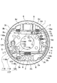
以下、図1〜3を参照しながら本発明の実施例1について詳細に説明する。説明に当たって、前述した従来技術のデュアルモードドラムブレーキ装置と同一の構成部品及び部位については同一の符号を付してその説明を省略し、従来技術の課題解決に寄与するパーキングブレーキ用アクチュエータ117の構成を中心に、100の位の符号を付して説明する。
【0020】
本例のパーキングブレーキ用アクチュエータ117は、第一のブレーキレバー118と第二のブレーキレバー119とストラット120等から成る。第一のブレーキレバー118は、その基部118aが第二のブレーキシュー3の両端部間にピン121で以って回転可能に枢支され、第二のブレーキレバー119は、その基部119aが第二のブレーキシュー3の下方端部3eにピン122で以って回転可能に枢支されている。そして、両ブレーキレバー118,119の自由端部118b,119bが互いに相近寄る方向に伸長され、第一のブレーキレバー118のブレーキ内方側に第二のブレーキレバー119が並列するよう配設されている。
【0021】
1枚の板体から成る第一のブレーキレバー118は、シューウェブ3bのバックプレート1側に重合して配設され、自由端部118bがU字形に折り返されて溝118cを形成している。
一方、1枚の板体から成る第二のブレーキレバー119は、その基部119a側がシューウェブ3bを挟持して対向するよう平行片に形成され、シューウェブ3bの内縁の近傍部から自由端部119bにかけてブレーキ内方側が開口する断面形状が略コ字形に折曲形成されている。
この自由端部119bの底部外面に第一のブレーキレバー118の基部118aと自由端部118b間に形成した突起118dが当接係合すると共に、第二のブレーキレバー119の基部119aと自由端部119b間がストラット120の左端部に当接係合している。
【0022】
長方形の平板から成るストラット120は、その左端の突出部120aが第二のブレーキレバー119のコ字形部に嵌入して幅方向の動きが制限されると共に、図2における上方の段付面120bがコ字形部の上方片に形成した切り欠き溝119c底に当接係合して板厚方向の移動が規制され、且つ、第二のブレーキレバー119の切り欠き溝119cは、ストラット120の板厚方向へ傾動し得るようテーパ状に形成されている。又、ストラット120の下方の段付面120cが第二のブレーキレバー119のコ字形部の下方片に当接係合している。更に、ストラット120の右端部は、その切り欠き溝120d底がピボットレバー16の下方端16bに当接係合している。尚、第二のブレーキレバー119のコ字形部の形状を、図1における上方端の開口を塞ぐよう絞り成型すれば自由端部119bの強度を向上し得る。
【0023】
しかして、第一のブレーキレバー118の溝118cに嵌入してケーブルエンド23aがシューリム3a側の端面に掛止されるブレーキケーブル23は、アンカーブロック7に隣接して第一のブレーキシュー2側に向けて配設され、ガイドパイプ26内を通してブレーキ外に延設されるから、足回り部品に邪魔されることない車軸の下方側に配索できる。
【0024】
続いて、前述した構成におけるパーキングブレーキ作動について説明する。図1において、ブレーキケーブル23により第一のブレーキレバー118の自由端部118bを牽引すると、第一のブレーキレバー118がピン121を支点に反時計方向に回転し、突起118dで以って第二のブレーキレバー119の自由端部119bを押圧する。この押圧力により、第二のブレーキレバー119がピン122を支点に時計方向に回転してストラット120、ピボットレバー16、シュー間隙調整装置9の順に押圧する。又、第二のブレーキレバー119の反力が、ストラット120との当接点を支点にピン122を介して第二のブレーキシュー3の下方端3eに作用する。これ以降のパーキングブレーキの作動については、前述した従来技術のパーキングブレーキ作動と同じであるからその説明を省略する。
【0025】
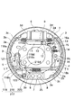
次に、図4,5を参照しながら本発明の実施例2について説明する。本例のパーキングブレーキ用アクチュエータ217は、前述した実施例1で示した第二のブレーキレバー119及びストラット120の形状が相違するのみであるから、当該部品に200の位を符し相違点のみについて説明する。
【0026】
第二のブレーキレバー219は、シューウェブ3bの内縁の近傍部から自由端部219bにかけてブレーキ外方側が開口する断面形状が略コ字形に折曲形成され、この自由端部219bの底部内面に第一のブレーキレバー118の突起118dが当接係合している。
又、長方形の平板から成るストラット220は、その左端に形成した凹溝220aが、第二のブレーキレバー219のコ字形部に形成したテーパ状の窪み219dに交差するように当接係合している。
上述した構造によれば、パーキングブレーキ作動時における第一のブレーキレバー118の捩れを補正できると共に、ブレーキ中央部のスペースを広く確保出来る利点も有する。
【0027】
【発明の効果】
本発明は、以上説明したようになるから次のような効果を得ることができる。
【0028】
<イ> 対向するブレーキシューの上方隣接端間にサービスブレーキ用アクチュエータを配設すると共に、下方隣接端間にアンカーを配設し、サービスブレーキ用アクチュエータに隣接して両ブレーキシュー間にシュー間隙調整装置を懸け渡すと共に、アンカーに隣接してパーキングブレーキ用アクチュエータを配設し、第一のブレーキシューにピボットレバーを回転可能に枢支し、このピボットレバーの上方と下方を、夫々シュー間隙調整装置とパーキングブレーキ用アクチュエータに係合するデュアルモードドラムブレーキ装置でありながら、パーキングブレーキ用アクチュエータが、第一のブレーキレバーの基部を第二のブレーキシューの両端部間に回転可能に枢支すると共にその自由端を下方に向け、第二のブレーキレバーの基部を第二のブレーキシューの下方端部に回転可能に枢支すると共にその自由端を上方に向け、第一のブレーキレバーのブレーキ内方側に第二のブレーキレバーが並列するよう配設し、第一のブレーキレバーがその基部と自由端部の間に前記第二のブレーキレバーの自由端部を係合すると共に、第二のブレーキレバーの両端部間と前記ピポットレバーの下方との間にストラットを懸け渡して構成され、第一のブレーキレバーの自由端部を牽引作動するブレーキケーブルを、アンカー側に隣接すると共に第一のブレーキシュー側に向けて配設したから、車軸の下方側から取り出せるようになり、ブレーキケーブルを足回り部品に邪魔されることなく容易に配索できる。
【0029】
<ロ> ブレーキレバーとストラット及びガイドパイプのバックプレートへの固定位置を変更するのみで、ブレーキケーブルの配設位置を、サービスブレーキ用アクチュエータとしてのホイールシリンダ側からアンカー側に移設できるので、その設計対応が容易である。
【0030】
<ハ> 第二のブレーキレバーの基部がシューウェブを挟持し、第一のブレーキレバーからの作用力をストラットに偏倚させることなく伝達でき、パーキングブレーキ用アクチュエータの強度上有利である。
【0031】
<ニ> 第二のブレーキレバーの自由端部に形成したコ字形部の底部内面に第一のブレーキレバーの突起部を収容して係合させる場合には、ブレーキ中央部の空間を広く確保できてレイアウトが容易になる。
【0032】
<ホ> ブレーキレバーのレバー比は、第一及び第二のブレーキレバーのレバー比を積算した値でよく、夫々のブレーキレバーのレバー比を小さく抑えられるので、板厚を薄く出来て軽量化が可能である。
【図面の簡単な説明】
【図1】 本発明の実施例1に係わるデュアルモードドラムブレーキ装置の正面図
【図2】 図1のII−II断面図
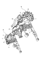
【図3】 図1の第二のブレーキシュー側の分解斜視図
【図4】 本発明の実施例2に係わるデュアルモードドラムブレーキ装置の正面図
【図5】 図4のV−V断面図
【図6】 従来のデュアルモードドラムブレーキ装置の正面図
【図7】 図6のVII−VII断面図
【図8】 車両のリヤ側プラットホーム部の一例を示す斜視図
【符号の説明】
1 バックプレート
2 第一のブレーキシュー
3 第二のブレーキシュー
6 ホイールシリンダ
7 アンカーブロック
9 シュー間隙調整装置
16 ピボットレバー
23 ブレーキケーブル
117 パーキングブレーキ用アクチュエータ
118 第一のブレーキレバー
119 第二のブレーキレバー
120 ストラット
217 パーキングブレーキ用アクチュエータ
219 第二のブレーキレバー
220 ストラット[0001]
BACKGROUND OF THE INVENTION
The present invention relates to a drum brake device, and more particularly to a dual mode drum brake device that operates as a leading / trailing type (LT type) brake during service braking and as a duo-servo type (DS type) brake during parking braking. Is.
[0002]
[Prior art]
This type of dual-mode drum brake device is disclosed in, for example, US Pat. No. 5,275,260, Japanese Patent Publication No. 62-8652 and Japanese Patent Application Laid-Open No. 9-273573. Since the structure of these drum brake devices is described in detail in the above-mentioned document, only an example thereof will be outlined here based on FIGS.
[0003]
The
[0004]
The opposing
[0005]
In FIG. 6, a
[0006]
Between the pair of
In addition, in the drawing, an automatic shoe clearance adjusting mechanism provided with an adjusting
[0007]
In the
[0008]
A
[0009]
In addition,
[0010]
Next, the brake operation in the above-described configuration will be described.
First, service brake operation will be described. When the
[0011]
Next, parking brake operation will be described. When the hand lever (not shown) is operated to pull the
[0012]
[Problems to be solved by the invention]
However, the above-described dual mode drum brake device has the following problems.
[0013]
FIG. 8 shows an example of a part of the chassis on the vehicle rear side. Drum brake devices a and a fixed to the left and right end surfaces of the axle housing b (for convenience of explanation, the
[0014]
The present invention has been made in view of the above-described problems. With a simple configuration in which only the parking brake actuator is changed, the brake cable is disposed on the lower side of the axle where the underbody parts do not interfere. An object of the present invention is to provide a dual-mode drum brake device that can perform the above-described operation.
[0015]
[Means for Solving the Problems]
To achieve the above object, in a dual-mode drum brake device according to the invention, an actuator for a parking brake is rotatably pivoted a base of the first brake lever between the ends of the second brake shoe With the free end facing downward, the base of the second brake lever pivotally supported on the lower end of the second brake shoe and the free end facing upward, with a second brake lever to the brake inner side is arranged to parallel, engaging the free end of the second brake lever between the base and the free end of the first brake lever pixels The strut is suspended between both ends of the second brake lever and below the pivot lever, and the free end of the first brake lever is pulled. That the brake cable, in which is disposed toward the first brake shoe side as well as adjacent to the anchor.
[0016]
Further, the second brake lever is composed of a single plate body, and the base side of the brake lever is formed as a parallel piece facing the shoe web so as to extend from the vicinity of the inner edge of the shoe web to the free end. It is good to form integrally so that the cross section may become a substantially U shape.
And it is good to engage a 1st brake lever with the bottom part outer surface or bottom part inner surface of a substantially U-shaped part.
[0017]
According to the dual mode drum brake device configured as described above, the drawing position of the brake cable that pulls the first brake lever from the back plate is on the anchor side, in other words, the position where the brake cable is routed is the axle. Therefore, the brake cable can be routed without being obstructed by the undercarriage parts of the vehicle.
[0018]
In addition to the fact that both the first and second brake levers can be easily integrally molded by pressing, the second brake lever is generated by the acting force of the first brake lever because the base portion sandwiches the shoe web. It is advantageous in terms of strength against the biasing force and can transmit the acting force from the first brake lever to the strut without being biased. In addition, the lever ratio of the brake lever may be a value obtained by integrating the lever ratios of the first and second brake levers. Since the lever ratio of each brake lever can be kept small, the plate thickness can be reduced and the weight can be reduced. It is.
[0019]
DETAILED DESCRIPTION OF THE INVENTION
Hereinafter, Example 1 of the present invention will be described in detail with reference to FIGS. In the description, the same components and parts as those of the above-described prior art dual mode drum brake device are denoted by the same reference numerals and the description thereof is omitted, and the configuration of the
[0020]
The
[0021]
The
On the other hand, the
With this outer bottom surface of the
[0022]
The
[0023]
Thus, the
[0024]
Next, the parking brake operation in the above-described configuration will be described. In FIG. 1, when the
[0025]
Next,
[0026]
The
Further, strut 220 made of a rectangular flat plate, the left end in the formed
According to the above-described structure, the twist of the
[0027]
【The invention's effect】
Since the present invention has been described above, the following effects can be obtained.
[0028]
<A> A service brake actuator is disposed between the upper adjacent ends of the opposing brake shoes, an anchor is disposed between the lower adjacent ends, and the shoe gap is adjusted between both brake shoes adjacent to the service brake actuator. The system is suspended and an actuator for a parking brake is provided adjacent to the anchor, and a pivot lever is pivotally supported on the first brake shoe, and a shoe gap adjusting device is provided above and below the pivot lever, respectively. as a yet dual mode drum brake device engaging the actuator for a parking brake, an actuator for a parking brake, with the base of the first brake lever rotatably pivoted between the ends of the second brake shoe With the free end facing down, the base of the second brake lever The second brake shoe is pivotally supported at the lower end of the second brake shoe and the free end thereof is directed upward, and the second brake lever is arranged in parallel with the inner side of the brake of the first brake lever . wherein the free end portion of the second brake lever while engaging, struts between the lower second end portions between said pivot lever of the brake lever between the base and the free end of the brake lever pixels Since the brake cable that is constructed by suspending and that pulls the free end portion of the first brake lever is disposed adjacent to the anchor side and toward the first brake shoe side, it can be taken out from the lower side of the axle. Thus, the brake cable can be easily routed without being disturbed by the suspension parts.
[0029]
<B> By simply changing the fixing position of the brake lever, strut, and guide pipe to the back plate, the brake cable can be moved from the wheel cylinder side to the anchor side as a service brake actuator. Easy to handle.
[0030]
<C> The base portion of the second brake lever holds the shoe web so that the acting force from the first brake lever can be transmitted to the strut without being biased, which is advantageous in terms of strength of the parking brake actuator.
[0031]
<D> When the protrusion of the first brake lever is accommodated and engaged with the inner surface of the bottom of the U-shaped part formed at the free end of the second brake lever, a large space in the center of the brake can be secured. Layout becomes easier.
[0032]
<E> The lever ratio of the brake levers may be a value obtained by integrating the lever ratios of the first and second brake levers. Since the lever ratio of each brake lever can be kept small, the plate thickness can be reduced and the weight can be reduced. Is possible.
[Brief description of the drawings]
FIG. 1 is a front view of a dual mode drum brake device according to a first embodiment of the present invention. FIG. 2 is a sectional view taken along the line II-II in FIG. 4 is a front view of a dual mode drum brake device according to a second embodiment of the present invention. FIG. 5 is a cross-sectional view taken along line V-V in FIG. 4. FIG. 6 is a front view of a conventional dual mode drum brake device. VII-VII sectional view of Fig. 6 [Fig. 8] A perspective view showing an example of a rear platform portion of a vehicle [Explanation of symbols]
DESCRIPTION OF
Claims (4)
前記パーキングブレーキ用アクチュエータが、第一のブレーキレバーの基部を第二のブレーキシューの両端部間に回転可能に枢支すると共にその自由端部を下方に向け、第二のブレーキレバーの基部を第二のブレーキシューの下方端部に回転可能に枢支すると共にその自由端部を上方に向け、第一のブレーキレバーのブレーキ内方側に第二のブレーキレバーが並列するよう配設し、前記第一のブレーキレバーがその基部と自由端部の間に前記第二のブレーキレバーの自由端部を係合すると共に、第二のブレーキレバーの両端部間と前記ピポットレバーの下方との間にストラットを懸け渡して構成され、
前記第一のブレーキレバーの自由端部を牽引作動するブレーキケーブルを、前記アンカーに隣接すると共に第一のブレーキシュー側に向けて配設したことを特徴とする、
デュアルモードドラムブレーキ装置。The first and second brake shoes are arranged opposite to each other on the back plate, the service brake actuator is arranged between the upper adjacent ends of the pair of brake shoes, and the anchor is arranged between the lower adjacent ends, A shoe clearance adjustment device is suspended between both brake shoes adjacent to the service brake actuator, and a parking brake actuator is disposed adjacent to the anchor so that a pivot lever can be rotated on the first brake shoe. pivoted, the upper and lower of the pivot lever, in the dual-mode drum brake device configured to engage the respective said shoe clearance adjustment device to the actuator for a parking brake,
The parking brake actuator pivotally supports the base portion of the first brake lever between both end portions of the second brake shoe and directs the free end portion downward, and the base portion of the second brake lever is The second brake shoe is pivotally supported at the lower end of the second brake shoe, the free end thereof is directed upward, and the second brake lever is arranged in parallel to the brake inward side of the first brake lever , while engaging the free end of the second brake lever between the base and the free end portion of the first brake lever pixels, between the lower second end portions between said pivot lever of the brake lever Is composed of struts
A brake cable that pulls and operates the free end of the first brake lever is disposed adjacent to the anchor and toward the first brake shoe.
Dual mode drum brake device.
Priority Applications (3)
| Application Number | Priority Date | Filing Date | Title |
|---|---|---|---|
| JP2002036667A JP3933487B2 (en) | 2002-02-14 | 2002-02-14 | Dual mode drum brake device |
| US10/361,218 US6766887B2 (en) | 2002-02-14 | 2003-02-10 | Dual mode type drum brake device |
| EP03290350A EP1336769A3 (en) | 2002-02-14 | 2003-02-13 | Dual mode type drum brake device |
Applications Claiming Priority (1)
| Application Number | Priority Date | Filing Date | Title |
|---|---|---|---|
| JP2002036667A JP3933487B2 (en) | 2002-02-14 | 2002-02-14 | Dual mode drum brake device |
Publications (2)
| Publication Number | Publication Date |
|---|---|
| JP2003240030A JP2003240030A (en) | 2003-08-27 |
| JP3933487B2 true JP3933487B2 (en) | 2007-06-20 |
Family
ID=27621417
Family Applications (1)
| Application Number | Title | Priority Date | Filing Date |
|---|---|---|---|
| JP2002036667A Expired - Fee Related JP3933487B2 (en) | 2002-02-14 | 2002-02-14 | Dual mode drum brake device |
Country Status (3)
| Country | Link |
|---|---|
| US (1) | US6766887B2 (en) |
| EP (1) | EP1336769A3 (en) |
| JP (1) | JP3933487B2 (en) |
Families Citing this family (7)
| Publication number | Priority date | Publication date | Assignee | Title |
|---|---|---|---|---|
| JP3933487B2 (en) * | 2002-02-14 | 2007-06-20 | 日清紡績株式会社 | Dual mode drum brake device |
| JP6114106B2 (en) * | 2012-07-25 | 2017-04-12 | 曙ブレーキ工業株式会社 | Drum brake device |
| JP2015172385A (en) * | 2014-03-11 | 2015-10-01 | 日信工業株式会社 | Vehicle brake device |
| US10138966B2 (en) | 2014-03-11 | 2018-11-27 | Nissin Kogyo Co., Ltd. | Vehicle brake apparatus |
| FR3057318B1 (en) * | 2016-10-12 | 2020-08-14 | Foundation Brakes France | DRUM BRAKE INTEGRATING A WELDED DOUBLE SIDED PARKING BRAKE ACTUATION LEVER |
| FR3057317B1 (en) * | 2016-10-12 | 2020-10-30 | Foundation Brakes France | DRUM BRAKE WITH INTEGRATED A DOUBLE-SIDED PARKING BRAKE ACTUATOR LEVER SNAP TO ONE TO THE OTHER |
| CN109712513B (en) * | 2019-03-06 | 2021-02-02 | 滨州学院 | Multipurpose globe is used to geography habit |
Family Cites Families (8)
| Publication number | Priority date | Publication date | Assignee | Title |
|---|---|---|---|---|
| JPS5610833A (en) | 1979-07-07 | 1981-02-03 | Toyota Motor Corp | Drum brake |
| JPH0652916B2 (en) | 1985-07-05 | 1994-07-06 | 富士ファコム制御株式会社 | Network controller |
| US5275260A (en) | 1989-09-18 | 1994-01-04 | Kelsey-Hayes Company | Dual mode drum brake assembly |
| JP3245768B2 (en) | 1996-04-03 | 2002-01-15 | 日清紡績株式会社 | Drum brake device |
| JP3838290B2 (en) * | 1996-06-28 | 2006-10-25 | トヨタ自動車株式会社 | Dual mode drum brake |
| JP4084899B2 (en) * | 1998-12-07 | 2008-04-30 | 豊生ブレーキ工業株式会社 | Dual mode drum brake |
| JP2002188665A (en) * | 2000-12-22 | 2002-07-05 | Nisshinbo Ind Inc | Brake drum device |
| JP3933487B2 (en) * | 2002-02-14 | 2007-06-20 | 日清紡績株式会社 | Dual mode drum brake device |
-
2002
- 2002-02-14 JP JP2002036667A patent/JP3933487B2/en not_active Expired - Fee Related
-
2003
- 2003-02-10 US US10/361,218 patent/US6766887B2/en not_active Expired - Fee Related
- 2003-02-13 EP EP03290350A patent/EP1336769A3/en not_active Withdrawn
Also Published As
| Publication number | Publication date |
|---|---|
| EP1336769A3 (en) | 2004-06-16 |
| US6766887B2 (en) | 2004-07-27 |
| US20030150676A1 (en) | 2003-08-14 |
| EP1336769A2 (en) | 2003-08-20 |
| JP2003240030A (en) | 2003-08-27 |
Similar Documents
| Publication | Publication Date | Title |
|---|---|---|
| JP3933487B2 (en) | Dual mode drum brake device | |
| JPH09273573A (en) | Drum braking device | |
| JP4006676B2 (en) | Pedal support structure | |
| JP5725286B2 (en) | Pad clip assembly structure | |
| JPH10299801A (en) | Drum brake device | |
| JP5548226B2 (en) | Caster braking structure | |
| CN102189982A (en) | Parking brake apparatus | |
| JP6761305B2 (en) | Vehicle drum brakes | |
| US6325183B2 (en) | Brake cable mounting structure for a drum brake | |
| CN101460759B (en) | Drum brakes | |
| US6390248B1 (en) | Dual mode drum brake device | |
| KR100808481B1 (en) | Parking brake for vehicle | |
| JP6761275B2 (en) | Vehicle drum brakes | |
| JPH1047396A (en) | Drum brake device | |
| US7490702B1 (en) | Parking and emergency brake actuator for a drum-in-hat disc brake assembly | |
| JP4828825B2 (en) | Parking brake assembly with automatic cable latching | |
| JP2002147506A (en) | Drum brake with shoe clearance automatic adjusting mechanism | |
| KR20090040072A (en) | Single shoe typed parking brake | |
| JP4540820B2 (en) | Drum brake and brake shoe | |
| US5096027A (en) | Drum brake | |
| JP3554949B2 (en) | Drum brake device | |
| JP2003314594A (en) | Drum brake device | |
| KR101064136B1 (en) | Drum brake | |
| JP2005344833A (en) | Back plate for vehicular drum brake | |
| US6554110B2 (en) | Drum brake device |
Legal Events
| Date | Code | Title | Description |
|---|---|---|---|
| A621 | Written request for application examination |
Free format text: JAPANESE INTERMEDIATE CODE: A621 Effective date: 20050111 |
|
| A977 | Report on retrieval |
Free format text: JAPANESE INTERMEDIATE CODE: A971007 Effective date: 20061101 |
|
| A131 | Notification of reasons for refusal |
Free format text: JAPANESE INTERMEDIATE CODE: A131 Effective date: 20061205 |
|
| A521 | Written amendment |
Free format text: JAPANESE INTERMEDIATE CODE: A523 Effective date: 20061228 |
|
| TRDD | Decision of grant or rejection written | ||
| A01 | Written decision to grant a patent or to grant a registration (utility model) |
Free format text: JAPANESE INTERMEDIATE CODE: A01 Effective date: 20070213 |
|
| A61 | First payment of annual fees (during grant procedure) |
Free format text: JAPANESE INTERMEDIATE CODE: A61 Effective date: 20070313 |
|
| R150 | Certificate of patent or registration of utility model |
Free format text: JAPANESE INTERMEDIATE CODE: R150 |
|
| LAPS | Cancellation because of no payment of annual fees |