WO2014017449A1 - 表面処理銅箔とその製造方法、リチウムイオン二次電池用電極及びリチウムイオン二次電池 - Google Patents
表面処理銅箔とその製造方法、リチウムイオン二次電池用電極及びリチウムイオン二次電池 Download PDFInfo
- Publication number
- WO2014017449A1 WO2014017449A1 PCT/JP2013/069832 JP2013069832W WO2014017449A1 WO 2014017449 A1 WO2014017449 A1 WO 2014017449A1 JP 2013069832 W JP2013069832 W JP 2013069832W WO 2014017449 A1 WO2014017449 A1 WO 2014017449A1
- Authority
- WO
- WIPO (PCT)
- Prior art keywords
- copper foil
- nitrogen
- carbon
- lithium ion
- secondary battery
- Prior art date
- Legal status (The legal status is an assumption and is not a legal conclusion. Google has not performed a legal analysis and makes no representation as to the accuracy of the status listed.)
- Ceased
Links
Images
Classifications
-
- H—ELECTRICITY
- H01—ELECTRIC ELEMENTS
- H01M—PROCESSES OR MEANS, e.g. BATTERIES, FOR THE DIRECT CONVERSION OF CHEMICAL ENERGY INTO ELECTRICAL ENERGY
- H01M4/00—Electrodes
- H01M4/02—Electrodes composed of, or comprising, active material
- H01M4/64—Carriers or collectors
- H01M4/66—Selection of materials
- H01M4/661—Metal or alloys, e.g. alloy coatings
-
- C—CHEMISTRY; METALLURGY
- C23—COATING METALLIC MATERIAL; COATING MATERIAL WITH METALLIC MATERIAL; CHEMICAL SURFACE TREATMENT; DIFFUSION TREATMENT OF METALLIC MATERIAL; COATING BY VACUUM EVAPORATION, BY SPUTTERING, BY ION IMPLANTATION OR BY CHEMICAL VAPOUR DEPOSITION, IN GENERAL; INHIBITING CORROSION OF METALLIC MATERIAL OR INCRUSTATION IN GENERAL
- C23C—COATING METALLIC MATERIAL; COATING MATERIAL WITH METALLIC MATERIAL; SURFACE TREATMENT OF METALLIC MATERIAL BY DIFFUSION INTO THE SURFACE, BY CHEMICAL CONVERSION OR SUBSTITUTION; COATING BY VACUUM EVAPORATION, BY SPUTTERING, BY ION IMPLANTATION OR BY CHEMICAL VAPOUR DEPOSITION, IN GENERAL
- C23C22/00—Chemical surface treatment of metallic material by reaction of the surface with a reactive liquid, leaving reaction products of surface material in the coating, e.g. conversion coatings, passivation of metals
- C23C22/05—Chemical surface treatment of metallic material by reaction of the surface with a reactive liquid, leaving reaction products of surface material in the coating, e.g. conversion coatings, passivation of metals using aqueous solutions
- C23C22/68—Chemical surface treatment of metallic material by reaction of the surface with a reactive liquid, leaving reaction products of surface material in the coating, e.g. conversion coatings, passivation of metals using aqueous solutions using aqueous solutions with pH between 6 and 8
-
- C—CHEMISTRY; METALLURGY
- C23—COATING METALLIC MATERIAL; COATING MATERIAL WITH METALLIC MATERIAL; CHEMICAL SURFACE TREATMENT; DIFFUSION TREATMENT OF METALLIC MATERIAL; COATING BY VACUUM EVAPORATION, BY SPUTTERING, BY ION IMPLANTATION OR BY CHEMICAL VAPOUR DEPOSITION, IN GENERAL; INHIBITING CORROSION OF METALLIC MATERIAL OR INCRUSTATION IN GENERAL
- C23F—NON-MECHANICAL REMOVAL OF METALLIC MATERIAL FROM SURFACE; INHIBITING CORROSION OF METALLIC MATERIAL OR INCRUSTATION IN GENERAL; MULTI-STEP PROCESSES FOR SURFACE TREATMENT OF METALLIC MATERIAL INVOLVING AT LEAST ONE PROCESS PROVIDED FOR IN CLASS C23 AND AT LEAST ONE PROCESS COVERED BY SUBCLASS C21D OR C22F OR CLASS C25
- C23F11/00—Inhibiting corrosion of metallic material by applying inhibitors to the surface in danger of corrosion or adding them to the corrosive agent
- C23F11/08—Inhibiting corrosion of metallic material by applying inhibitors to the surface in danger of corrosion or adding them to the corrosive agent in other liquids
- C23F11/10—Inhibiting corrosion of metallic material by applying inhibitors to the surface in danger of corrosion or adding them to the corrosive agent in other liquids using organic inhibitors
- C23F11/14—Nitrogen-containing compounds
- C23F11/149—Heterocyclic compounds containing nitrogen as hetero atom
-
- H—ELECTRICITY
- H01—ELECTRIC ELEMENTS
- H01M—PROCESSES OR MEANS, e.g. BATTERIES, FOR THE DIRECT CONVERSION OF CHEMICAL ENERGY INTO ELECTRICAL ENERGY
- H01M4/00—Electrodes
- H01M4/02—Electrodes composed of, or comprising, active material
- H01M4/64—Carriers or collectors
- H01M4/66—Selection of materials
-
- H—ELECTRICITY
- H01—ELECTRIC ELEMENTS
- H01M—PROCESSES OR MEANS, e.g. BATTERIES, FOR THE DIRECT CONVERSION OF CHEMICAL ENERGY INTO ELECTRICAL ENERGY
- H01M4/00—Electrodes
- H01M4/02—Electrodes composed of, or comprising, active material
- H01M4/13—Electrodes for accumulators with non-aqueous electrolyte, e.g. for lithium-accumulators; Processes of manufacture thereof
-
- Y—GENERAL TAGGING OF NEW TECHNOLOGICAL DEVELOPMENTS; GENERAL TAGGING OF CROSS-SECTIONAL TECHNOLOGIES SPANNING OVER SEVERAL SECTIONS OF THE IPC; TECHNICAL SUBJECTS COVERED BY FORMER USPC CROSS-REFERENCE ART COLLECTIONS [XRACs] AND DIGESTS
- Y02—TECHNOLOGIES OR APPLICATIONS FOR MITIGATION OR ADAPTATION AGAINST CLIMATE CHANGE
- Y02E—REDUCTION OF GREENHOUSE GAS [GHG] EMISSIONS, RELATED TO ENERGY GENERATION, TRANSMISSION OR DISTRIBUTION
- Y02E60/00—Enabling technologies; Technologies with a potential or indirect contribution to GHG emissions mitigation
- Y02E60/10—Energy storage using batteries
Definitions
- the present invention is a surface-treated copper foil excellent in resistance weldability, particularly a copper foil mutually welded, or copper foil to each other, or a copper foil and another metal material welded by resistance welding, a method for producing the same, and
- the present invention relates to an electrode for a lithium ion secondary battery and a lithium ion secondary battery used.
- the electrical connection portion is required to be more reliable, and in particular, in connection portions between terminals and dissimilar metals such as copper foil, It is required to be more reliably joined.
- a negative electrode current collector of a non-aqueous solvent secondary battery such as a lithium ion secondary battery
- a strong bonding strength or a highly reliable bonding state is required to connect copper foils or copper foil and tab terminals. It is done.
- resistance welding In this resistance welding method, in the joining of dissimilar metals, a fused part called nugget is formed in the joining part, and stable joining where peeling of the joining part is hard to occur is possible, especially large metal parts such as automobile bodies.
- a fused part called nugget is formed in the joining part, and stable joining where peeling of the joining part is hard to occur is possible, especially large metal parts such as automobile bodies.
- ultrasonic welding friction between copper foils for current collectors and tab plates for copper foils-terminals is different. Therefore, by appropriately adjusting the current, pressure, and welding time and selecting the condition that does not generate spatter, generation of copper particulates and mixing in the battery cell can be prevented, and the safety of the lithium ion secondary battery It also contributes to securing.
- the ultrasonic weldability of the copper foil is better if the surface is not subjected to anti-corrosion treatment when pretreatment such as heat drying is not performed.
- pretreatment such as heat drying
- the surface of the copper foil is easily oxidized in the air if it is not subjected to antirust treatment, it is not suitable for practical use regardless of the presence or absence of pretreatment such as heat drying.
- chromate treatment is carried out in an acidic bath (pH 1 to 2) to form a chromium hydrate oxide film called a chromate film, and immersion in a solution containing a triazole compound and tetrazole compound Methods are known for forming organic rustproof coatings.
- the copper foil coated with the rustproof film in this way is difficult to discolor in the atmosphere, but on the other hand, if the thickness of the rustproof film is thick, the surface is difficult to be cleaned even when ultrasonic vibration is applied, and pure copper Since it is hard to be exposed to the surface, atomic diffusion is unlikely to occur and it is considered that the bonding strength is weakened.
- the present inventors have found a clue to the prevention of corrosion by the organic component centering on triazole compounds and the control of the surface resistance. Therefore, as a result of examining the antirust treatment conditions, the total content of nitrogen and carbon contained in the antirust film is obtained by treating with an antirust solution in which a triazole compound and a predetermined ratio of carboxylic anhydride are mixed. Based on JIS K ⁇ 7194: 1994, it forms the rustproof film which is the highest on the outermost surface and is characterized by changes in the total content of nitrogen and carbon in the depth direction, and controls the concentration of triazole compounds. By making the measured surface resistance value into a fixed range, it discovered that an electrolytic copper foil with a good resistance welding characteristic was obtained.
- the surface-treated copper foil of the present invention is the sum of the elemental content (atomic%) of carbon and nitrogen in the depth direction of the copper foil measured by XPS (X-ray photoelectron spectroscopy) on at least one surface of the copper foil. Is the largest at the outermost surface of the copper foil, and at a depth at which the sum of the elemental contents (atomic%) of carbon and nitrogen is half the value relative to the outermost surface, carbon in the depth direction of the copper foil A surface-treated film is formed which has a total reduction of the element content (atomic%) of nitrogen of 50% / nm or more and a surface resistance of 2.5 to 40 m ⁇ as defined in JIS-K7194: 1994. It is characterized by
- the method for producing a surface-treated copper foil according to the present invention contains 50 to 700 ppm of a triazole compound such that the concentration ratio of the carboxylic anhydride to the total concentration of the triazole compound is 0.05 or more.
- a triazole compound such that the concentration ratio of the carboxylic anhydride to the total concentration of the triazole compound is 0.05 or more.
- the surface-treated copper foil excellent in the weldability of copper foils by resistance welding, or copper foil and other metals can be provided.
- the surface treatment method of the copper foil excellent in resistance weldability of the present invention easily produces a surface-treated copper foil excellent in weldability between copper foils by resistance welding or between copper foil and another metal.
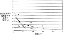
- FIG. 1 is a graph showing the sum of the elemental content (atomic%) of carbon and nitrogen in the depth direction of a copper foil measured by XPS (X-ray photoelectron spectroscopy) according to an example.
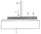
- FIG. 2 is an explanatory view schematically showing resistance welding.
- the surface-treated copper foil of the present invention at least one surface of the copper foil (in the present invention, when the electrolytic copper foil and the rolled copper foil need not be individually expressed, they are collectively referred to as copper foil)
- the elemental content (atomic%) of carbon and nitrogen in the depth direction of the copper foil is the largest at the outermost surface by XPS (X-ray photoelectron spectroscopy), and the total elemental content (atomic%) of carbon and nitrogen is the outermost surface
- the reduction rate of the total of the elemental content (atomic%) of carbon and nitrogen in the depth direction of the copper foil is 50% / nm or more, and the resistance value on the copper foil surface is 2
- An organic anticorrosion coating comprising a triazole compound or a complex compound thereof having a mixture of 5 to 40 m ⁇ or a mixture of these two compounds (herein, an organic anticorrosion coating comprising a triazole compound or a complex compound thereof or a mixture of both of them; Triazole compound, and / or to as organic anti-
- X-ray photoelectron spectroscopy (XPS) and argon sputtering are combined to perform elemental analysis in the depth direction, thereby detecting and quantifying carbon and nitrogen of a rust preventive film formed on the surface of a copper foil.
- the anticorrosive film is a complex of copper and a triazole compound and a mixture of a pure triazole compound, and the volume resistivity of the copper foil body is on the order of 10 5 to 10 6 times.
- the resistance value becomes higher as the thickness of the insulating film becomes larger.
- a measured value of surface resistance of one copper foil based on JIS-K7194: 1994 is adopted as an index of the thickness of the antirust film.
- the elemental content (atomic%) of carbon and nitrogen in the depth direction of the copper foil by XPS (X-ray photoelectron spectroscopy), The reduction rate [% / nm] of the sum of the elemental content of carbon and nitrogen at the depth position where the sum of the elemental content of nitrogen is half of the outermost surface is used.
- the thickness of the anticorrosive film and the adhesion amount of the triazole compound, that is, the total amount of carbon and nitrogen derived from the triazole compound are determined by the treatment concentration and treatment temperature of the triazole compound used for the antirust treatment.
- the sum of carbon and nitrogen contents takes a maximum value near the outermost surface of the film, and decreases to draw an asymptotic line as it proceeds in the depth direction, and finally becomes 0%. That is, if the reduction in the element content [% / nm] at the depth position where the sum of the element contents of carbon and nitrogen is half of the outermost surface is large, most of the carbon and nitrogen derived from the triazole compound It can be considered that it exists on the outermost surface of the antirust film, and the anticorrosive component is densely present on the outermost surface of the antirust film.
- the resistance value on the copper foil surface of this embodiment is 0.25 to 40 m ⁇ . If it is smaller than 0.25 m ⁇ , the ability to protect the copper foil surface from air or moisture at room temperature is poor, and surface oxidation or discoloration tends to occur during storage and transportation. In addition, in a high temperature environment of 100 to 160 ° C such as the drying step in the production of the negative electrode current collector of the non-aqueous solvent secondary battery, the strength of the antirust film is insufficient to prevent oxidation, and the oxide film thickness becomes too thick. This is because the weldability is extremely reduced due to an excessive increase.
- the resistance value on the copper foil surface is larger than 40 m ⁇ , the thickness of the anticorrosion film itself is excessive, so the thermal energy at the time of welding is consumed excessively for the removal of the anticorrosion film, which is sufficient. It is because there is a possibility that a strong welding state can not be obtained.
- the resistance value on the copper foil surface is more preferable in the range of 0.25 to 20 m ⁇ than in the range of 20 to 40 m ⁇ because the anticorrosive film is easily removed during welding.
- the compound contains 50 to 700 ppm of a triazole compound, and the concentration ratio of the carboxylic anhydride to the total concentration of the triazole compound is 0.05 or more.
- the anticorrosive treatment solution prepared as described above is applied to the copper foil to form an anticorrosive coating on at least one surface of the copper foil.
- triazole compounds examples include benzotriazole, tolyltriazole, carboxybenzotriazole, chlorobenzotriazole, ethylbenzotriazole, naphthotriazole and the like, and complex compounds thereof.
- carboxylic acid anhydride examples include acetic anhydride, succinic anhydride, maleic anhydride, propionic anhydride, and phthalic anhydride.
- concentration of the triazole compound in the antirust treatment solution is desirably 50 to 700 ppm. If it is less than 50 ppm, the surface resistance value is less than 2.5 m ⁇ , and oxidation or discoloration of the surface is likely to occur during heating during storage, transport and drying steps.
- the concentration ratio of carboxylic anhydrides to triazole compounds is desirably 0.05 or more.
- the concentration ratio of carboxylic anhydrides to triazole compounds is lower than 0.05, the sum of the elemental contents of carbon and nitrogen at a depth position at which the sum of the elemental contents of carbon and nitrogen is a half value with respect to the outermost surface Less than 50% / nm.
- the difference between the contents of carbon and nitrogen between the outermost surface of the anticorrosive film and the inside becomes smaller, and the anticorrosive component is insufficient near the outermost surface of the anticorrosive film, and the oxide film is generated in the heating process of the welding pretreatment.
- the thickness tends to increase, and satisfactory weldability may not be obtained.
- the immersion time may be usually about 0.5 to 30 seconds.
- the conditions of the manufacturing method of the surface-treated copper foil of this embodiment are not limited above.
- the cathode or / and anode is 0.1 to 5 minutes. It is effective to carry out electrolytic degreasing.
- the heat energy at the time of welding be easily transmitted between the foils if the 10-point average surface roughness Rz of the copper foil is 2.5 ⁇ m or less.
- the triazole compound is benzotriazole (1,2,3-benzotriazole: BTA), tolyltriazole (5-methyl-1H-benzotriazole: TTA), ethylbenzotriazole 5-ethyl-1H-benzotriazole: 1 to 3 selected from the following EBTA to give a total concentration of 50 to 700 ppm, and carboxylic acid anhydrides selected from succinic anhydride, maleic anhydride and propionic anhydride
- the steel sheet was immersed in a rustproofing solution prepared so that the concentration ratio to the total concentration of the triazole compound was in the range of 0.05 or more to apply a rustproof film to the surface of the copper foil.
- the liquid temperature was 35 to 55 ° C., and the pH was 6.5 to 8.0.
- the element content (atomic%) in the depth direction of nitrogen and carbon was measured under the following conditions using an XPS measurement apparatus 5600 MC manufactured by ULVAC-PHI, Inc. Ultimate vacuum degree 1 ⁇ 10 -10 Torr (1 ⁇ 10 -8 Torr when Ar gas introduced), X-ray: X-ray type monochromatized Al-k ⁇ ray, output 300 W, detection area 800 ⁇ m ⁇ , Ion beam: ion species Ar +, acceleration voltage 3 kV, sweep area 3 ⁇ 3 mm 2 , Sample incident angle 45 ° (angle between sample and detector), Sputtering rate 2.3 nm / min (SiO 2 equivalent) A curve is created by adding the contents of nitrogen and carbon, with the element content (atomic%) on the vertical axis and the depth direction on the horizontal axis, and a tangent at the depth position that is half the content of the outermost surface The concentration reduction degree [% / nm] was calculated from the slope of this tangent line.
- FIG. 1 is a graph showing the sum of the elemental content (atomic%) of carbon and nitrogen in the depth direction of a copper foil measured by XPS (X-ray photoelectron spectroscopy) according to an example.
- the solid line a in FIG. 1 shows an example of the total element content (atomic%) of carbon and nitrogen in the depth direction in Examples 1 to 12.
- the broken line b in FIG. 1 shows an example of the total element content (atomic%) of carbon and nitrogen in the depth direction in Comparative Examples 1-9.
- the sum of the elemental content of carbon and nitrogen in the depth direction of the copper foil is the largest at the outermost surface.
- the reduction rate of the total of the carbon and nitrogen elemental contents in the depth direction of the copper foil at the depth at which the sum of the carbon and nitrogen elemental contents is half with respect to the outermost surface is the solid line a.
- the slope of the tangent line Sa of the graph indicated by the solid line a at the half value depth is indicated by a broken line b, and the inclination of the tangent line Sb of the graph indicated by the broken line b at the half value value is indicated.
- the area of the region sandwiched by the solid line a and the x axis according to the example corresponds to the elemental content of carbon and nitrogen in the rustproof coating of the example.
- the area of the region sandwiched by the broken line b and the x axis according to the comparative example corresponds to the elemental content of carbon and nitrogen in the rustproof coating of the comparative example.
- the element content of carbon and nitrogen is equivalent in the example and the comparative example, and the area between the solid line a and the x axis and the area between the dashed line b and x axis The area of is equal.
- the surface resistance of the copper foil was measured by a four-terminal method based on JIS-K7194: 1994, using a resistance meter RM3544 manufactured by Nitoki Denki.
- FIG. 2 is an explanatory view schematically showing resistance welding.
- a tab copper plate 2 having a thickness of 200 ⁇ m is disposed on the lower electrode (copper stage-like electrode) 1, and 20 sample copper foils 3 are disposed in a stacked manner on the tab copper plate 2.
- the upper electrode (copper alumina alloy rod-shaped electrode, ⁇ 3.2 mm) 4 is pressed to the welded portion of the sample copper foil 3, current I flows between the upper electrode 4 and the lower electrode 1, and resistance welding is performed.
- Examples 1 to 12 are excellent in resistance weldability to facilitate assembly of electronic parts and the like, and are excellent even if this copper foil is used as a current collector for non-aqueous secondary batteries such as Li batteries. Brought an effect.
- the present invention can provide a surface-treated copper foil excellent in weldability between copper foils by resistance welding or between the copper foil and another metal.
- the surface treatment method of copper foil excellent in resistance welding according to the present invention can easily produce a surface-treated copper foil excellent in weldability between copper foils by resistance welding or between copper foil and another metal. it can.
- the surface-treated copper foil of the present invention can be preferably applied to an electrode for a lithium ion secondary battery using the negative electrode current collector. Furthermore, it can be preferably applied to a lithium ion secondary battery using the lithium ion secondary battery electrode as a negative electrode.
Landscapes
- Chemical & Material Sciences (AREA)
- Engineering & Computer Science (AREA)
- Materials Engineering (AREA)
- Chemical Kinetics & Catalysis (AREA)
- General Chemical & Material Sciences (AREA)
- Mechanical Engineering (AREA)
- Metallurgy (AREA)
- Organic Chemistry (AREA)
- Electrochemistry (AREA)
- Preventing Corrosion Or Incrustation Of Metals (AREA)
- Cell Electrode Carriers And Collectors (AREA)
Abstract
Description
また近年、リチウムイオン二次電池等の非水溶媒二次電池の負極集電体として、銅箔同士、あるいは銅箔とタブ端子の接続には強い接合強度、もしくは信頼性の高い接合状態が求められている。
この抵抗溶接法は異種金属同士の接合ではその接合部にナゲットと呼ばれる溶融部分が形成され、接合部の剥離が発生しにくい安定した接合が可能で、特に自動車のボディのような大型の金属部品の接合では多く用いられている。
リチウムイオン二次電池の分野においては、強度が大きく信頼性の高い接合状態が得られるだけでなく、超音波溶接とは異なり集電体用銅箔間および銅箔-端子用タブ板間において摩擦が発生しないため、電流・圧力・溶接時間を適切に調節してスパッタを発生させない条件を選択することにより、銅微粒子の発生と電池セルへの混入が予防でき、リチウムイオン二次電池の安全性確保にも寄与する。
このように防錆被膜を施した銅箔は、大気中で変色し難いが、一方で防錆被膜の厚さが厚い場合、超音波振動を印加しても、表面がクリーニングされにくく、純銅が表面に露出しにくいため、原子拡散が起こり難く、接合力が弱められるためであると考えられる。
また、本発明の抵抗溶接性に優れた銅箔の表面処理方法は、抵抗溶接による銅箔同士、あるいは銅箔と他の金属との溶接性に優れた表面処理銅箔を容易に製造することができる。
銅箔表面における抵抗値の測定はJIS-K7194:1994に基づき測定する。
防錆処理に用いたトリアゾール系化合物の処理濃度・処理温度により、防錆皮膜の厚さと、トリアゾール系化合物の付着量、すなわちトリアゾール系化合物由来の炭素と窒素の総量が決定される。また、炭素と窒素の含有率の合計は、皮膜の最表面付近で最大値をとり、深さ方向に進むにしたがって漸近線を描くように減少し、最終的に0%となる。
つまり、炭素と窒素の元素含有率の合計が最表面の半値となる深さ位置での元素含有率の減少度[%/nm]が大きければ、トリアゾール系化合物由来の炭素と窒素の大部分が防錆皮膜の最表面に存在し、防錆皮膜の最表面に防錆成分が密に存在していると考えることができる。一方、この値が小さければ、トリアゾール系化合物由来の炭素と窒素の存在率は、最表面と皮膜の中央部との間で差が小さいだけでなく、最表面付近の炭素と窒素の存在率が低くなり、防錆成分は密な存在状態とはなっていないと考えることができる。
以上の点から、炭素と窒素の元素含有率の合計が最表面の半値となる深さ位置での、炭素と窒素の元素含有率の合計の減少度[%/nm]は、防錆皮膜の最表面付近のトリアゾール系化合物由来の炭素と窒素が多量に、かつ密に存在しているか否かの尺度となる。
この数値が50%/nmよりも小さい場合、防錆皮膜表面付近のトリアゾール系化合物由来の炭素と窒素が不足して、溶接前処理の加熱工程において熱された大気や水分と銅箔との接触を抑制しきれずに酸化膜厚が増大しやすくなり、満足する溶接性が得られないおそれがある。
銅箔表面における抵抗値は、0.25~20mΩの範囲の方が、20~40mΩの範囲に比べて、溶接時に防錆皮膜が除去されやすく、より好適である。
防錆処理液におけるトリアゾール化合物の濃度は50~700ppmとすることが望ましい。50ppmを下回ると表面の抵抗値は2.5mΩを下回り、保管、輸送及び乾燥工程時の加熱において表面の酸化あるいは変色が発生しやすい。一方で700ppmを超えると、表面の抵抗値が40mΩを上回り、防錆皮膜の厚さそのものが過剰なものとなり、溶接時の熱エネルギーが防錆皮膜の除去のために過大に消費され、十分な強度の溶接状態が得られないおそれがある。
また、無水カルボン酸類のトリアゾール系化合物に対する濃度比は0.05以上とすることが望ましい。無水カルボン酸類のトリアゾール系化合物に対する濃度比が0.05より低い場合、最表面に対して炭素と窒素の元素含有率の合計が半値となる深さ位置における、炭素と窒素の元素含有率の合計の減少度が50%/nmを下回る。その結果、防錆皮膜の最表面付近と内部との炭素と窒素の含有率の差が小さくなり、防錆成分が防錆皮膜の最表面付近で不足し、溶接前処理の加熱工程で酸化膜厚が増大しやすくなり、満足する溶接性が得られないおそれがある。
また、トリアゾール成分の安定性を確保するため、溶液の温度を35~55℃、pHを6.5~8.0とすることが好ましい。また、浸漬時間は通常0.5~30秒程度であればよい。
ただし、本実施形態の表面処理銅箔の製造方法の条件は、上記に限定されるものではない。
製箔後ただちに防錆処理できない場合は、前処理として、H2SO4=5~200g/l、温度=10℃~80℃の希硫酸に浸漬する酸洗い方法が効果的である。また、脱脂の場合は、NaOH=5~200g/l、温度=10℃~80℃の水溶液中で、電流密度=1~10A/dm2、0.1分~5分で陰極又は/及び陽極電解脱脂を行うのが効果的である。
次に示す組成の電解液を調整し、アノードには貴金属酸化物被覆チタン電極、カソードにはチタン製回転ドラムを用いて、電流密度=50~100A/dm2で厚さ10μmの電解銅箔を製造した。
銅: 70~130g/l
硫酸: 80~140g/l
添加剤: 3-メルカプト1-プロパンスルホン酸ナトリウム=1~10ppm
ヒドロキシエチルセルロース=1~100ppm
低分子量膠(分子量3,000)=1~50ppm
塩化物イオン濃度=10~50ppm
温度: 50~60℃
〔実施例1~9〕
電解製箔された銅箔をただちに、トリアゾール系化合物をベンゾトリアゾール(1,2,3-ベンゾトリアゾール:以下BTA)、トリルトリアゾール(5-メチル-1H-ベンゾトリアゾール:以下TTA)、エチルベンゾトリアゾール(5-エチル-1H-ベンゾトリアゾール:以下EBTA)から1~3種類選択して合計濃度が50~700ppmとなり、かつ、無水カルボン酸類を無水コハク酸、無水マレイン酸、無水プロピオン酸から1種類選択してトリアゾール系化合物の合計濃度に対する濃度比が0.05以上の範囲となるように調製した防錆処理液に浸漬し、銅箔表面に防錆皮膜を施した。なお、液温は35~55℃、pHは6.5~8.0とした。
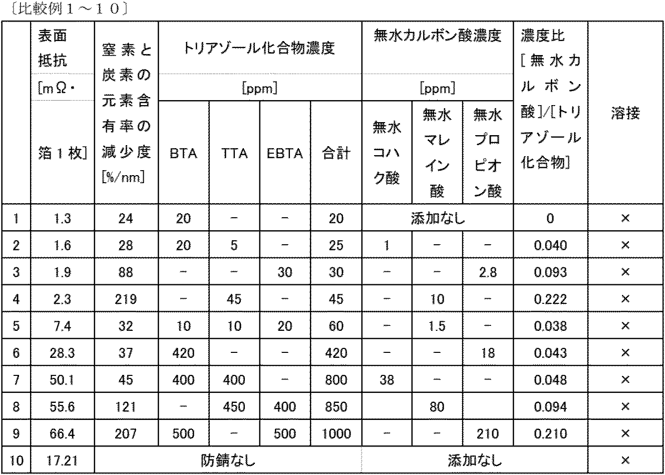
電解製箔された銅箔をただちに、トリアゾール系化合物をBTA、TTA、EBTAから1~3種類選択して合計濃度が50ppmを下回り、かつ、無水カルボン酸類を無水コハク酸、無水マレイン酸、無水プロピオン酸から1種類選択して任意の濃度となるように調製した防錆処理液に浸漬し、銅箔表面に防錆皮膜を施した。なお、液温は35~55℃、pHは6.5~8.0とした。
〔比較例5~6〕
電解製箔された銅箔をただちに、トリアゾール系化合物をBTA、TTA、EBTAから1~3種類選択して合計濃度が50~700ppmとなり、かつ、無水カルボン酸類を無水コハク酸、無水マレイン酸、無水プロピオン酸から1種類選択してトリアゾール系化合物の合計濃度に対する濃度比が0.05未満の範囲となるように調製した防錆処理液に浸漬し、銅箔表面に防錆皮膜を施した。なお、液温は35~55℃、pHは6.5~8.0とした。
〔比較例7~9〕
電解製箔された銅箔をただちに、トリアゾール系化合物をBTA、TTA、EBTAから1~3種類選択して合計濃度が700ppmを上回り、かつ、無水カルボン酸類を無水コハク酸、無水マレイン酸、無水プロピオン酸から1種類選択して任意の濃度となるように調製した防錆処理液に浸漬し、銅箔表面に防錆皮膜を施した。なお、液温は35~55℃、pHは6.5~8.0とした。
〔比較例10〕
電解製箔された銅箔に対し、防錆処理剤の塗布を行わず、そのままの状態とした。
窒素及び炭素の深さ方向の元素含有率(原子%)を、アルバック・ファイ株式会社製XPS測定装置5600MCを使用し下記条件で測定した。
到達真空度1×10⁻¹⁰Torr(Arガス導入時1×10⁻⁸Torr)、
X線:X線種単色化Al-kα線、出力300W、検出面積800μmφ、
イオン線:イオン種Ar+、加速電圧3kV、掃引面積3×3mm2、
試料入射角45°(試料と検出器とのなす角)、
スパッタリングレート2.3nm/分(SiO2換算)
元素含有率(原子%)を縦軸、深さ方向を横軸として、窒素と炭素の含有率を合算した曲線を作成し、最表面の含有率に対して半値となる深さ位置において接線を作成し、この接線の傾きから濃度減少度[%/nm]を算出した。
図1中の実線aは、実施例1~12の深さ方向の炭素と窒素の合計の元素含有率(原子%)の一例を示す。
図1中の破線bは、比較例1~9の深さ方向の炭素と窒素の合計の元素含有率(原子%)の一例を示す。
実線aと破線bの両者において、銅箔の深さ方向に対する炭素と窒素の元素含有率の合計が最表面で最も大きい。ここで、炭素と窒素の元素含有率の合計が最表面に対して半値となる深さにおける、銅箔の深さ方向に対する炭素と窒素の元素含有率の合計の減少度は、実線aにおいては、半値となる深さにおける実線aで示されるグラフの接線Saの傾きで示され、破線bにおいては、半値となる深さにおける破線bで示されるグラフの接線Sbの傾きで示される。
実施例に係る実線aとx軸で挟まれた領域の面積は、実施例の防錆皮膜中の炭素と窒素の元素含有量に相当する。同様に、比較例に係る破線bとx軸で挟まれた領域の面積は、比較例の防錆皮膜中の炭素と窒素の元素含有量に相当する。同じ防錆皮膜厚さの場合、実施例と比較例で同等の炭素と窒素の元素含有量となり、実線aとx軸で挟まれた領域の面積と、破線bとx軸で挟まれた領域の面積は同等になる。
銅箔の表面抵抗については、JIS-K7194:1994に基づく4端子法により、日置電機製抵抗計RM3544を使用して測定を行った。
前処理として、真空乾燥機中(ヤマト科学製ADP200)で銅箔を140℃の温度で1時間、100Paの圧力で減圧乾燥した。
図2は抵抗溶接を模式的に示す説明図である。下部電極(銅製ステージ状電極)1上に200μmの厚さのタブ銅板2が配置され、その上に試料銅箔3が20枚積層して配置される。試料銅箔3の溶接箇所に上部電極(銅アルミナ合金製棒状電極、φ3.2mm)4が押圧され、上部電極4と下部電極1間で電流Iが流され、抵抗溶接がなされる。
溶接機として日本アビオニクス製NRW-200Aを用い、ピーク値2400A、通電時間4.9msのパルス電流、および33Nの圧力を印加して、図2に示すように10μm厚の銅箔20枚を200μm厚のタブ銅板に溶接した。
上記条件で溶接した後、上側電極に接触していた最表層の銅箔の溶接部分を20倍の倍率で光学顕微鏡にて観察してクラックが発生していないことを確認し、溶接した銅箔を最表層の銅箔から順に1枚ずつ剥離した。15枚以上の銅箔が溶接部分で破れた場合を◎、10~14枚の銅箔が溶接部分で破れた場合を○、溶接部分で破れた銅箔が9枚以下、もしくは、まったく接合していない場合を×とした。

また、本発明の抵抗溶接に優れた銅箔の表面処理方法は、抵抗溶接による銅箔同士、あるいは銅箔と他の金属との溶接性に優れた表面処理銅箔を容易に製造することができる。
本発明の表面処理銅箔を負極集電体として用いて、リチウムイオン二次電池用電極に好ましく適用できる。
さらに、リチウムイオン二次電池用電極を負極として用いて、リチウムイオン二次電池に好ましく適用できる。
Claims (6)
- 銅箔の少なくとも片方の面において、XPS(X線光電子分光分析)により測定された銅箔の深さ方向の炭素と窒素の元素含有率(原子%)の合計が該銅箔の最表面で最も大きく、かつ、その炭素と窒素の元素含有率(原子%)の合計が最表面に対して半値となる深さにおいて、該銅箔の深さ方向に対する炭素と窒素の元素含有率(原子%)の合計の減少度が50%/nm以上であり、かつ、JIS-K7194:1994において規定される表面抵抗が2.5~40mΩである表面処理皮膜が形成されていることを特徴とする、表面処理銅箔。
- 銅箔の少なくとも片方の面において、XPS(X線光電子分光分析)により測定された銅箔の深さ方向の炭素と窒素の元素含有率(原子%)の合計が該銅箔の最表面で最も大きく、かつ、その炭素と窒素の元素含有率(原子%)の合計が最表面に対して半値となる深さにおいて、該銅箔の深さ方向に対する炭素と窒素の元素含有率(原子%)の合計の減少度が50%/nm以上であり、かつ、JIS-K7194:1994において規定される表面抵抗が2.5~20mΩである表面処理皮膜が形成されていることを特徴とする、表面処理銅箔。
- リチウムイオン二次電池の負極集電体として用いられることを特徴とする請求項1又は請求項2に記載の表面処理銅箔。
- トリアゾール系化合物を50~700ppm含有し、カルボン酸無水物をトリアゾール系化合物の合計濃度に対して濃度比が0.05以上の範囲となるように調製した防錆処理液を銅箔に塗布する工程を含むことを特徴とする、請求項1~3の表面処理銅箔を製造する、表面処理銅箔の製造方法。
- 請求項1~3に記載の前記表面処理銅箔を負極集電体として用いた、リチウムイオン二次電池用電極。
- 請求項4に記載のリチウムイオン二次電池用電極を負極として用いた、リチウムイオン二次電池。
Priority Applications (3)
| Application Number | Priority Date | Filing Date | Title |
|---|---|---|---|
| JP2013541902A JP5554455B1 (ja) | 2012-07-23 | 2013-07-22 | 表面処理銅箔とその製造方法、リチウムイオン二次電池用電極及びリチウムイオン二次電池 |
| CN201380015937.XA CN104204299B (zh) | 2012-07-23 | 2013-07-22 | 表面处理铜箔及其制造方法、锂离子二次电池用电极以及锂离子二次电池 |
| KR1020147028373A KR101579489B1 (ko) | 2012-07-23 | 2013-07-22 | 표면 처리 동박과 그 제조방법, 리튬이온 이차전지용 전극 및 리튬이온 이차전지 |
Applications Claiming Priority (2)
| Application Number | Priority Date | Filing Date | Title |
|---|---|---|---|
| JP2012-163061 | 2012-07-23 | ||
| JP2012163061 | 2012-07-23 |
Publications (1)
| Publication Number | Publication Date |
|---|---|
| WO2014017449A1 true WO2014017449A1 (ja) | 2014-01-30 |
Family
ID=49997260
Family Applications (1)
| Application Number | Title | Priority Date | Filing Date |
|---|---|---|---|
| PCT/JP2013/069832 Ceased WO2014017449A1 (ja) | 2012-07-23 | 2013-07-22 | 表面処理銅箔とその製造方法、リチウムイオン二次電池用電極及びリチウムイオン二次電池 |
Country Status (5)
| Country | Link |
|---|---|
| JP (1) | JP5554455B1 (ja) |
| KR (1) | KR101579489B1 (ja) |
| CN (1) | CN104204299B (ja) |
| TW (1) | TWI508359B (ja) |
| WO (1) | WO2014017449A1 (ja) |
Cited By (2)
| Publication number | Priority date | Publication date | Assignee | Title |
|---|---|---|---|---|
| JP2021157889A (ja) * | 2020-03-25 | 2021-10-07 | 株式会社Gsユアサ | 電池用基材及び電池 |
| CN121593147A (zh) * | 2026-01-30 | 2026-03-03 | 帕珂表面处理技术(上海)有限公司 | 一种铜系金属材料用表面处理剂、带皮膜的铜系金属材料的制造方法、及铜系金属材料的防蚀方法 |
Families Citing this family (1)
| Publication number | Priority date | Publication date | Assignee | Title |
|---|---|---|---|---|
| CN116337906A (zh) * | 2023-02-28 | 2023-06-27 | 广西大学 | 一种x射线光电子能谱仪粉末样品制备方法 |
Citations (5)
| Publication number | Priority date | Publication date | Assignee | Title |
|---|---|---|---|---|
| JPS62270785A (ja) * | 1986-05-19 | 1987-11-25 | Chiyoda Kagaku Kenkyusho:Kk | 銅及び銅合金の耐熱性防食剤 |
| JPH07258870A (ja) * | 1994-03-24 | 1995-10-09 | Mitsui Mining & Smelting Co Ltd | 有機防錆処理銅箔およびその製造方法 |
| JP2011023303A (ja) * | 2009-07-17 | 2011-02-03 | Jx Nippon Mining & Metals Corp | リチウムイオン電池集電体用銅箔 |
| JP2011149098A (ja) * | 2009-12-25 | 2011-08-04 | Furukawa Electric Co Ltd:The | 表面処理銅箔及び表面処理銅箔の製造方法 |
| JP2013079419A (ja) * | 2011-10-03 | 2013-05-02 | Jx Nippon Mining & Metals Corp | 銅箔及びそれを用いたリチウムイオン二次電池用負極集電体及び負極材、ならびにリチウムイオン二次電池 |
Family Cites Families (3)
| Publication number | Priority date | Publication date | Assignee | Title |
|---|---|---|---|---|
| CN113571772A (zh) * | 2005-10-20 | 2021-10-29 | 三菱化学株式会社 | 锂二次电池以及其中使用的非水电解液 |
| JP5306620B2 (ja) | 2007-09-11 | 2013-10-02 | 古河電気工業株式会社 | 超音波溶接用銅箔、およびその表面処理方法 |
| JP5448616B2 (ja) * | 2009-07-14 | 2014-03-19 | 古河電気工業株式会社 | 抵抗層付銅箔、該銅箔の製造方法および積層基板 |
-
2013
- 2013-07-22 WO PCT/JP2013/069832 patent/WO2014017449A1/ja not_active Ceased
- 2013-07-22 TW TW102126050A patent/TWI508359B/zh active
- 2013-07-22 JP JP2013541902A patent/JP5554455B1/ja active Active
- 2013-07-22 CN CN201380015937.XA patent/CN104204299B/zh active Active
- 2013-07-22 KR KR1020147028373A patent/KR101579489B1/ko active Active
Patent Citations (5)
| Publication number | Priority date | Publication date | Assignee | Title |
|---|---|---|---|---|
| JPS62270785A (ja) * | 1986-05-19 | 1987-11-25 | Chiyoda Kagaku Kenkyusho:Kk | 銅及び銅合金の耐熱性防食剤 |
| JPH07258870A (ja) * | 1994-03-24 | 1995-10-09 | Mitsui Mining & Smelting Co Ltd | 有機防錆処理銅箔およびその製造方法 |
| JP2011023303A (ja) * | 2009-07-17 | 2011-02-03 | Jx Nippon Mining & Metals Corp | リチウムイオン電池集電体用銅箔 |
| JP2011149098A (ja) * | 2009-12-25 | 2011-08-04 | Furukawa Electric Co Ltd:The | 表面処理銅箔及び表面処理銅箔の製造方法 |
| JP2013079419A (ja) * | 2011-10-03 | 2013-05-02 | Jx Nippon Mining & Metals Corp | 銅箔及びそれを用いたリチウムイオン二次電池用負極集電体及び負極材、ならびにリチウムイオン二次電池 |
Cited By (3)
| Publication number | Priority date | Publication date | Assignee | Title |
|---|---|---|---|---|
| JP2021157889A (ja) * | 2020-03-25 | 2021-10-07 | 株式会社Gsユアサ | 電池用基材及び電池 |
| JP7524572B2 (ja) | 2020-03-25 | 2024-07-30 | 株式会社Gsユアサ | 電池用基材及び電池 |
| CN121593147A (zh) * | 2026-01-30 | 2026-03-03 | 帕珂表面处理技术(上海)有限公司 | 一种铜系金属材料用表面处理剂、带皮膜的铜系金属材料的制造方法、及铜系金属材料的防蚀方法 |
Also Published As
| Publication number | Publication date |
|---|---|
| KR101579489B1 (ko) | 2015-12-22 |
| CN104204299A (zh) | 2014-12-10 |
| KR20150035502A (ko) | 2015-04-06 |
| JP5554455B1 (ja) | 2014-07-23 |
| JPWO2014017449A1 (ja) | 2016-07-11 |
| CN104204299B (zh) | 2016-02-24 |
| TW201405925A (zh) | 2014-02-01 |
| TWI508359B (zh) | 2015-11-11 |
Similar Documents
| Publication | Publication Date | Title |
|---|---|---|
| JP5714575B2 (ja) | 表面処理銅箔 | |
| JP5675325B2 (ja) | 表面処理銅箔及び表面処理銅箔の製造方法 | |
| TWI593826B (zh) | Copper foil for lithium ion secondary battery negative electrode current collector | |
| JP2010242195A (ja) | 異種金属接触腐食に対する防食性に優れた表面処理金属材及びその表面処理金属材を備えた異材接合体 | |
| JP5081481B2 (ja) | 濡れ性に優れた銅箔及びその製造方法 | |
| JP5306620B2 (ja) | 超音波溶接用銅箔、およびその表面処理方法 | |
| JP5554455B1 (ja) | 表面処理銅箔とその製造方法、リチウムイオン二次電池用電極及びリチウムイオン二次電池 | |
| JP5773093B2 (ja) | 容器用鋼板 | |
| JP6098709B2 (ja) | 容器用鋼板 | |
| JP5669352B2 (ja) | 異種金属接触腐食に対する防食性に優れた異材接合体 | |
| JP2018135570A (ja) | Sn系合金めっき鋼板及びSn系合金めっき鋼板の製造方法 | |
| JPWO2014156362A1 (ja) | 表面処理電解銅箔 | |
| JPWO2014156361A1 (ja) | 表面処理電解銅箔 |
Legal Events
| Date | Code | Title | Description |
|---|---|---|---|
| WWE | Wipo information: entry into national phase |
Ref document number: 201380015937.X Country of ref document: CN |
|
| ENP | Entry into the national phase |
Ref document number: 2013541902 Country of ref document: JP Kind code of ref document: A |
|
| 121 | Ep: the epo has been informed by wipo that ep was designated in this application |
Ref document number: 13823557 Country of ref document: EP Kind code of ref document: A1 |
|
| ENP | Entry into the national phase |
Ref document number: 20147028373 Country of ref document: KR Kind code of ref document: A |
|
| NENP | Non-entry into the national phase |
Ref country code: DE |
|
| 122 | Ep: pct application non-entry in european phase |
Ref document number: 13823557 Country of ref document: EP Kind code of ref document: A1 |