WO2014017229A1 - ZnO膜の製造装置及び製造方法 - Google Patents
ZnO膜の製造装置及び製造方法 Download PDFInfo
- Publication number
- WO2014017229A1 WO2014017229A1 PCT/JP2013/066863 JP2013066863W WO2014017229A1 WO 2014017229 A1 WO2014017229 A1 WO 2014017229A1 JP 2013066863 W JP2013066863 W JP 2013066863W WO 2014017229 A1 WO2014017229 A1 WO 2014017229A1
- Authority
- WO
- WIPO (PCT)
- Prior art keywords
- raw material
- gas
- zno film
- material container
- temperature
- Prior art date
- Legal status (The legal status is an assumption and is not a legal conclusion. Google has not performed a legal analysis and makes no representation as to the accuracy of the status listed.)
- Ceased
Links
Images










Classifications
-
- C—CHEMISTRY; METALLURGY
- C23—COATING METALLIC MATERIAL; COATING MATERIAL WITH METALLIC MATERIAL; CHEMICAL SURFACE TREATMENT; DIFFUSION TREATMENT OF METALLIC MATERIAL; COATING BY VACUUM EVAPORATION, BY SPUTTERING, BY ION IMPLANTATION OR BY CHEMICAL VAPOUR DEPOSITION, IN GENERAL; INHIBITING CORROSION OF METALLIC MATERIAL OR INCRUSTATION IN GENERAL
- C23C—COATING METALLIC MATERIAL; COATING MATERIAL WITH METALLIC MATERIAL; SURFACE TREATMENT OF METALLIC MATERIAL BY DIFFUSION INTO THE SURFACE, BY CHEMICAL CONVERSION OR SUBSTITUTION; COATING BY VACUUM EVAPORATION, BY SPUTTERING, BY ION IMPLANTATION OR BY CHEMICAL VAPOUR DEPOSITION, IN GENERAL
- C23C16/00—Chemical coating by decomposition of gaseous compounds, without leaving reaction products of surface material in the coating, i.e. chemical vapour deposition [CVD] processes
- C23C16/22—Chemical coating by decomposition of gaseous compounds, without leaving reaction products of surface material in the coating, i.e. chemical vapour deposition [CVD] processes characterised by the deposition of inorganic material, other than metallic material
- C23C16/30—Deposition of compounds, mixtures or solid solutions, e.g. borides, carbides, nitrides
- C23C16/40—Oxides
- C23C16/407—Oxides of zinc, germanium, cadmium, indium, tin, thallium or bismuth
-
- B—PERFORMING OPERATIONS; TRANSPORTING
- B05—SPRAYING OR ATOMISING IN GENERAL; APPLYING FLUENT MATERIALS TO SURFACES, IN GENERAL
- B05C—APPARATUS FOR APPLYING FLUENT MATERIALS TO SURFACES, IN GENERAL
- B05C19/00—Apparatus specially adapted for applying particulate materials to surfaces
- B05C19/06—Storage, supply or control of the application of particulate material; Recovery of excess particulate material
-
- C—CHEMISTRY; METALLURGY
- C23—COATING METALLIC MATERIAL; COATING MATERIAL WITH METALLIC MATERIAL; CHEMICAL SURFACE TREATMENT; DIFFUSION TREATMENT OF METALLIC MATERIAL; COATING BY VACUUM EVAPORATION, BY SPUTTERING, BY ION IMPLANTATION OR BY CHEMICAL VAPOUR DEPOSITION, IN GENERAL; INHIBITING CORROSION OF METALLIC MATERIAL OR INCRUSTATION IN GENERAL
- C23C—COATING METALLIC MATERIAL; COATING MATERIAL WITH METALLIC MATERIAL; SURFACE TREATMENT OF METALLIC MATERIAL BY DIFFUSION INTO THE SURFACE, BY CHEMICAL CONVERSION OR SUBSTITUTION; COATING BY VACUUM EVAPORATION, BY SPUTTERING, BY ION IMPLANTATION OR BY CHEMICAL VAPOUR DEPOSITION, IN GENERAL
- C23C16/00—Chemical coating by decomposition of gaseous compounds, without leaving reaction products of surface material in the coating, i.e. chemical vapour deposition [CVD] processes
- C23C16/44—Chemical coating by decomposition of gaseous compounds, without leaving reaction products of surface material in the coating, i.e. chemical vapour deposition [CVD] processes characterised by the method of coating
- C23C16/448—Chemical coating by decomposition of gaseous compounds, without leaving reaction products of surface material in the coating, i.e. chemical vapour deposition [CVD] processes characterised by the method of coating characterised by the method used for generating reactive gas streams, e.g. by evaporation or sublimation of precursor materials
- C23C16/4488—Chemical coating by decomposition of gaseous compounds, without leaving reaction products of surface material in the coating, i.e. chemical vapour deposition [CVD] processes characterised by the method of coating characterised by the method used for generating reactive gas streams, e.g. by evaporation or sublimation of precursor materials by in situ generation of reactive gas by chemical or electrochemical reaction
-
- C—CHEMISTRY; METALLURGY
- C23—COATING METALLIC MATERIAL; COATING MATERIAL WITH METALLIC MATERIAL; CHEMICAL SURFACE TREATMENT; DIFFUSION TREATMENT OF METALLIC MATERIAL; COATING BY VACUUM EVAPORATION, BY SPUTTERING, BY ION IMPLANTATION OR BY CHEMICAL VAPOUR DEPOSITION, IN GENERAL; INHIBITING CORROSION OF METALLIC MATERIAL OR INCRUSTATION IN GENERAL
- C23C—COATING METALLIC MATERIAL; COATING MATERIAL WITH METALLIC MATERIAL; SURFACE TREATMENT OF METALLIC MATERIAL BY DIFFUSION INTO THE SURFACE, BY CHEMICAL CONVERSION OR SUBSTITUTION; COATING BY VACUUM EVAPORATION, BY SPUTTERING, BY ION IMPLANTATION OR BY CHEMICAL VAPOUR DEPOSITION, IN GENERAL
- C23C16/00—Chemical coating by decomposition of gaseous compounds, without leaving reaction products of surface material in the coating, i.e. chemical vapour deposition [CVD] processes
- C23C16/44—Chemical coating by decomposition of gaseous compounds, without leaving reaction products of surface material in the coating, i.e. chemical vapour deposition [CVD] processes characterised by the method of coating
- C23C16/52—Controlling or regulating the coating process
-
- H—ELECTRICITY
- H10—SEMICONDUCTOR DEVICES; ELECTRIC SOLID-STATE DEVICES NOT OTHERWISE PROVIDED FOR
- H10P—GENERIC PROCESSES OR APPARATUS FOR THE MANUFACTURE OR TREATMENT OF DEVICES COVERED BY CLASS H10
- H10P14/00—Formation of materials, e.g. in the shape of layers or pillars
- H10P14/20—Formation of materials, e.g. in the shape of layers or pillars of semiconductor materials
- H10P14/24—Formation of materials, e.g. in the shape of layers or pillars of semiconductor materials using chemical vapour deposition [CVD]
-
- H—ELECTRICITY
- H10—SEMICONDUCTOR DEVICES; ELECTRIC SOLID-STATE DEVICES NOT OTHERWISE PROVIDED FOR
- H10P—GENERIC PROCESSES OR APPARATUS FOR THE MANUFACTURE OR TREATMENT OF DEVICES COVERED BY CLASS H10
- H10P14/00—Formation of materials, e.g. in the shape of layers or pillars
- H10P14/20—Formation of materials, e.g. in the shape of layers or pillars of semiconductor materials
- H10P14/34—Deposited materials, e.g. layers
- H10P14/3402—Deposited materials, e.g. layers characterised by the chemical composition
- H10P14/3424—Deposited materials, e.g. layers characterised by the chemical composition being Group IIB-VIA materials
- H10P14/3426—Oxides
Definitions
- Embodiments of the present invention relate to a ZnO film manufacturing apparatus and manufacturing method.
- a ZnO film is known as an element useful for various electronic elements such as a solar cell, a surface acoustic wave element, a resonator, a photoacoustic element, a light emitting diode, and a laser diode.
- a ZnO film manufacturing apparatus and manufacturing method are described in Patent Document 1, for example.
- zinc iodide (ZnI) is used as a Zn raw material, and this is heated at 380 ° C., and oxygen gas is supplied onto the substrate to react Zn and O 2 , and a ZnO film is formed on the substrate.
- ZnI zinc iodide
- a technique for epitaxial growth is disclosed.
- a similar technique disclosed in Patent Document 2 is also known.
- the quality of the ZnO film is low, and the FWHM (full width at half maximum) in X-ray diffraction is 20 to 80 (min). That is, the FWHM of the ZnO film is 1200 arcsec at the maximum.
- This invention is made
- a ZnO film manufacturing apparatus includes an installation table on which a substrate on which a ZnO film is to be formed, a reaction container that houses the installation table, and the reaction container A first raw material containing portion that communicates with the interior and contains a solid raw material containing Zn, a second raw material containing portion that communicates with the interior of the reaction vessel and contains a solid raw material containing Zn, the installation table, Heating means for heating the first raw material container, the second raw material container, a chlorine gas supply source for supplying chlorine gas to at least the first raw material container, and oxygen for supplying oxygen gas into the reaction vessel A gas supply source; and a control device, wherein the control device has a temperature T1 of the first raw material container, a temperature T2 of the second raw material container, and a temperature T3 of the installation table on which the substrate is disposed.
- the heating means is controlled so as to satisfy the relationship of 1 ⁇ T2 ⁇ T3, the flow rate of chlorine gas supplied from the chlorine gas supply source to the first raw material storage unit is controlled, and the oxygen gas supply source To control the flow rate of oxygen gas supplied into the reaction vessel.
- first and second raw material accommodating portions having different temperatures T1 and T2 at the time of ZnO film formation
- chlorine gas is supplied to at least one
- Zn solid raw material and chlorine gas (Cl 2 ) To generate ZnCl 2
- Zn itself is gasified by heating and reacts with oxygen gas on the substrate surface.
- the first ZnO film manufacturing apparatus further includes a carrier gas supply source that supplies a carrier gas to the second raw material container, and includes the first raw material container and the second raw material container.
- the accommodating portion can control the flow rate of the gas emitted from them independently of each other, and the direction of gas emission from the first raw material accommodating portion and the amount of gas from the second raw material accommodating portion. It is characterized by being spaced apart so that the emission directions are different.
- the carrier gas supply source can transport this in the direction of the substrate when Zn is gasified.
- the carrier gas supply source may contain chlorine gas.
- the first raw material container and the second raw material container may be configured such that the gas passing through the first raw material container is the second raw material container. It is characterized by being continuous so as to pass through the raw material container.
- ZnCl 2 is generated by the reaction between the Zn solid raw material and chlorine gas (Cl 2 ), and Zn itself is gasified by heating and reacts with oxygen gas on the substrate surface.
- ZnCl 2 , Zn Zn-based materials
- oxygen oxygen
- gaseous Zn is supplied from a different location from ZnCl 2 , but there is no reason to prevent both gases from going through the same path, and high quality ZnO. It was confirmed that the membrane could be manufactured.
- the control device controls the amount of chlorine gas supplied from the chlorine gas supply source, and the partial pressure of zinc chloride gas is 8.8 ⁇ 10 ⁇ 5 atm in the region immediately above the substrate surface. It is preferable to set the pressure to 3.6 ⁇ 10 ⁇ 4 atm or less. This is because the ZnO film grows when the partial pressure of the chlorine-zinc gas exceeds the lower limit, but the etching of the ZnO film starts and the ZnO film does not grow when the partial pressure exceeds the upper limit. Note that the near region is defined as a region within 1 cm from the substrate surface in a direction perpendicular to the surface.
- the control device controls the amount of chlorine gas supplied from the chlorine gas supply source, and the partial pressure of zinc chloride gas is 8.8 ⁇ 10 ⁇ 5 atm or more in the vicinity region immediately above the substrate surface. It is preferable to set the pressure to 3 ⁇ 10 ⁇ 4 atm or less. This is because the ZnO film grows sufficiently when the partial pressure of the chlorine gas is within this range.
- the control device controls the amount of chlorine gas supplied from the chlorine gas supply source, and the partial pressure of zinc chloride gas is 8.8 ⁇ 10 ⁇ 5 atm or more in the vicinity region immediately above the substrate surface. It is preferable to set the pressure to 2.2 ⁇ 10 ⁇ 4 atm or less. This is because when the partial pressure of the chlorine zinc gas is within this range, the growth rate of the ZnO film is constant and stable control is possible.
- the first raw material storage unit and the second raw material storage unit are configured such that the gas that has passed through the first raw material storage unit passes through the second raw material storage unit.
- the bottom surfaces of the first and second raw material storage portions are continuous so as to pass through, and the depth from the horizontal plane located above the bottom surfaces is directed to the gas outlet of the second raw material storage portion. It is characterized by being inclined so as to become deeper.
- the solid raw material containing Zn approaches the side closer to the gas outlet by gravity along the bottom surface. Therefore, even if the amount of the solid raw material varies, the solid raw material can be arranged with high reproducibility, the variation in the position of the solid raw material can be suppressed, and the quality of the ZnO film can be stabilized.
- the chlorine gas is supplied from the chlorine gas supply source to the first raw material container by the installation step of placing the substrate on the installation base and the control device.
- the temperature T1 of the first raw material container, the temperature T2 of the second raw material container, and the installation table on which the substrate is disposed And a film forming step for controlling the heating means so that the temperature T3 satisfies a relationship of T1 ⁇ T2 ⁇ T3.
- a high-quality ZnO film can be manufactured as described above.
- the ZnO film manufacturing apparatus includes an installation table on which a substrate on which a ZnO film is to be formed is disposed, a reaction vessel that houses the installation table, and a reaction vessel that contains Zn.
- the temperature T1 of the raw material container and the temperature T2 of the second raw material container satisfy the relationship of T1 ⁇ T2 when the ZnO film is formed. In this case, a high-quality ZnO film can be manufactured as described above.
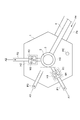
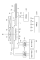
- FIG. 1 is a plan view of the first ZnO film manufacturing apparatus.
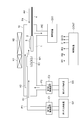
- FIG. 2 is a plan view of a manufacturing apparatus obtained by modifying the first ZnO film manufacturing apparatus.
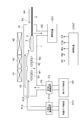
- FIG. 3 is a view showing a vertical cross-sectional configuration passing through the first gas supply pipe P1 of the manufacturing apparatus shown in FIG.
- FIG. 4 is a view showing a vertical cross-sectional configuration passing through the second gas supply pipe P2 of the manufacturing apparatus shown in FIG.
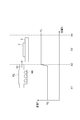
- FIG. 5 is a diagram showing the first raw material container and the substrate together with a graph showing the relationship between the position and temperature.
- FIG. 6 is a diagram showing the second raw material container and the substrate together with a graph showing the relationship between these positions and temperatures.
- FIG. 1 is a plan view of the first ZnO film manufacturing apparatus.
- FIG. 2 is a plan view of a manufacturing apparatus obtained by modifying the first ZnO film manufacturing apparatus.
- FIG. 3 is a view showing a vertical cross-sectional configuration passing through the first gas supply pipe P
- FIG. 7 is a diagram showing a longitudinal sectional configuration of the second ZnO film manufacturing apparatus.
- FIG. 8 is a diagram showing the first and second raw material storage units and the substrate together with a graph showing the relationship between these positions and temperatures.
- FIG. 9 is a view showing a longitudinal cross-sectional configuration of a manufacturing apparatus obtained by modifying the second ZnO film manufacturing apparatus.
- FIG. 10 is a view showing a longitudinal sectional configuration of a manufacturing apparatus obtained by modifying the ZnO film manufacturing apparatus shown in FIG.
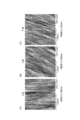
- FIG. 11 is a diagram showing an atomic force microscope (AFM) image of the surface of the ZnO film.
- AFM atomic force microscope
- FIG. 12 is a graph showing the relationship between the angle ⁇ (°) of the X-ray diffraction direction and the intensity (au) with respect to the X-ray incident direction in the X-ray diffraction measurement.
- FIG. 13 is a graph showing the relationship between the depth ( ⁇ m) in the ZnO film and the impurity concentration (cm ⁇ 3 ).
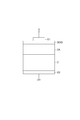
- FIG. 14 is a diagram showing a structure of a MOS diode for CV measurement.
- FIG. 15 is a graph showing the relationship between voltage (V) and capacity per unit area (F / cm 2 ).
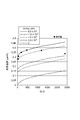
- FIG. 16 is a graph showing the relationship between ZnCl 2 partial pressure (atm) and growth rate ( ⁇ m / h).
- FIG. 17 is a graph showing the relationship between temperature T (° C.) and Zn partial pressure (atm).
- FIG. 18 is a graph showing the relationship between VI / II and the growth rate ( ⁇ m / h).
- FIG. 19 is a graph showing the relationship between ZnCl 2 partial pressure (atm) and Cl 2 partial pressure (atm).
- FIG. 20 is a graph showing the relationship between the deposition time (hour) of the ZnO film, the thickness ( ⁇ m), and the growth rate ( ⁇ m / h).
- FIG. 21 is a graph (A) showing the relationship between the temperature T (° C.) and the growth rate ( ⁇ m / h), and a graph (B) showing the relationship between the substrate position (cm) and the growth rate ( ⁇ m / h).
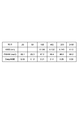
- FIG. 22 is a chart showing the characteristics of the ZnO film for various conditions.
- FIG. 23 is a chart showing the characteristics of the ZnO film for various conditions.
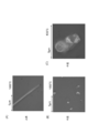
- FIG. 24 is a view showing a photomicrograph of the substrate surface when only a single raw material container having a constant temperature is provided.
- FIG. 25 is a diagram showing a micrograph of the substrate surface when only a single raw material container having a constant temperature is provided for each change in the chlorine gas concentration.
- FIG. 1 is a plan view of a first ZnO film manufacturing apparatus.
- This ZnO film manufacturing apparatus includes an installation table 3 on which a substrate (wafer) 2 on which a ZnO film is to be formed is disposed, and a reaction vessel 1 that houses the installation table 3.
- a first raw material storage part (chamber) R1 and a second raw material storage part (chamber) R2 are arranged in the reaction vessel 1, but the first raw material storage part R1 and the second raw material storage part R2 are arranged. May be arranged outside the reaction vessel 1.
- At least the first raw material storage portion R1 communicates with the inside of the reaction vessel 1 and stores the solid raw material M1 containing Zn.
- the second raw material storage unit R2 communicates with the inside of the reaction vessel 1 and stores the solid raw material M2 containing Zn.
- the substrate 2 is a 1 cm square ZnO substrate manufactured by a hydrothermal synthesis method.
- This manufacturing apparatus further includes heating means (H3, H1, H2) for heating the installation base 3, the first raw material storage unit R1, and the second raw material storage unit R2.
- the heating means includes heaters H1, H2, and H3 for heating each element.
- As the heater resistance heating, lamp heating, high-frequency heating, and the like are known.
- a heating furnace using resistance heating is employed.
- the heaters H1, H2, and H3 heat the first raw material storage unit R1, the second raw material storage unit R2, and the setting table 3 by energizing them.
- the solid raw material containing Zn is metallic Zn, but it is possible to contain impurities to the extent that the results are not greatly affected.
- the reaction vessel 1 is used at normal pressure (1 atm (atm)), but may be a reduced pressure environment.
- the first gas (chlorine gas or the like) A1 and the second gas (carrier gas or the like) A2 are each indicated by an arrow through a relatively low temperature first raw material storage portion R1 and a relatively high temperature second raw material storage portion R2. It can introduce
- the first gas A1 is introduced into the first raw material storage unit R1 through the first supply pipe P1, and after reacting with the solid raw material, the first gas A1 is directed toward the substrate 2 disposed inside the reaction vessel 1.
- the second gas A2 is introduced into the second raw material container R2 through the second supply pipe P2, and after reacting with the solid raw material, the second gas A2 is directed toward the substrate 2 disposed inside the reaction vessel 1. Flowing.
- the third gas A3 and the fourth gas A4 flow into the reaction vessel 1 through the third supply pipe P3 and the fourth supply pipe P4, respectively, and flow toward the substrate 2.
- An exhaust device is connected to the reaction vessel 1, and the internal gas is discharged to the outside through the exhaust pipe PE.
- the installation table 3 is transferred into the reaction vessel 1 by a transfer arm (rod) 4 with the installation table 3 fixed to the tip.
- the setting table 3 may be fixed in the reaction vessel 1 and the substrate transfer arm 4 may be configured to retract to the outside of the reaction vessel 1 after transferring the substrate 2 to the setting table 3. It is.
- the reaction vessel 1 may be provided with a load lock chamber for loading and unloading the substrate to / from the outside and a processing apparatus (deposition apparatus such as a sputtering apparatus, etching apparatus, etc.) for processing other materials as necessary. it can.
- FIG. 2 is a plan view of a manufacturing apparatus obtained by modifying the first ZnO film manufacturing apparatus.
- the third supply pipe P3 is connected to the side surface of the reaction vessel 1 and extends in the horizontal direction.
- the third supply pipe P3 is connected to the bottom surface of the reaction vessel and is vertical. Extending in the direction.
- the third supply pipe P3 may extend horizontally from the reaction vessel 1 after extending in the vertical direction. Note that the connection position of other supply pipes can also be changed to the side surface, bottom surface, or top surface of the reaction vessel 1.
- FIG. 3 is a view showing a vertical cross-sectional configuration passing through the first gas supply pipe P1 of the manufacturing apparatus shown in FIG.
- the first gas supply source G1 is connected to the first supply pipe P1 via the first flow rate control device C1, and the first supply pipe P1 is connected to the first raw material storage portion R1, and the gas outlet is the substrate. It faces the direction of 2.
- the third gas supply source G3 is connected to the third supply pipe P3 via the third flow rate controller C3, and the third supply pipe P3 communicates with the inside of the reaction vessel 1.
- the introduced third gas A3 flows in the direction of the substrate 2.
- the fourth gas A4 is introduced into the reaction vessel from a carrier gas supply source (not shown), and the fourth gas A4 flows toward the substrate 2.
- FIG. 4 is a view showing a vertical cross-sectional configuration passing through the second gas supply pipe P2 of the manufacturing apparatus shown in FIG.
- the second gas supply source G2 is connected to the second supply pipe P2 via the second flow rate control device C2, and the second supply pipe P2 is connected to the second raw material storage part R2, and the gas outlet is the substrate. It faces the direction of 2.
- the gas introduced into the reaction vessel 1 is exhausted by the exhaust device EX1 through the exhaust pipe PE.
- the temperature T1 of the first raw material container R1, the temperature T2 of the second raw material container R2, and the temperature T3 of the installation table 3 on which the substrate 2 is arranged are formed of the ZnO film.
- the heating means H1, H2, H3 are controlled so as to satisfy the relationship of T1 ⁇ T2 ⁇ T3.
- the flow rate of the chlorine gas supplied from the first gas supply source (chlorine gas supply source) G1 to the first raw material container R1 is controlled, and the third gas supply source ( The flow rate of oxygen gas supplied from the oxygen gas supply source G3 into the reaction vessel 1 is controlled.
- the control device CONT controls the heaters H1, H2, H3 and the flow rate control devices C1, C2, C3.
- the second gas supply source G2 is a carrier gas supply source that supplies a carrier gas (N 2 ) to the second raw material container R2.
- the first raw material storage unit R1 and the second raw material storage unit R2 can control the flow rates of the gas emitted from them independently of each other, and the first raw material storage unit R1 from the first raw material storage unit R1.
- the gas emission direction and the gas emission direction from the second raw material container R2 are different from each other so as to be different from each other.
- the carrier gas from the second gas supply source G2 (carrier gas supply source) can be transported in the direction of the substrate 2 when Zn is gasified (sublimated).
- This carrier gas supply source may contain chlorine gas. That is, at least the first raw material container R1 is supplied with chlorine gas from a chlorine gas supply source, but the chlorine gas can also be supplied to the second raw material container R2.
- the first gas A1, the second gas A2, the third gas A3, and the fourth gas A4 are specifically as follows.
- the first gas A1 contains chlorine gas and nitrogen gas.
- the second gas A2 contains nitrogen gas, but can also contain chlorine gas.
- the third gas A3 is oxygen gas, but can also contain nitrogen gas.
- the fourth gas A4 is nitrogen gas. Note that an inert gas such as argon can be used instead of the nitrogen gas as the carrier gas.
- FIG. 5 is a diagram showing the first raw material container and the substrate together with a graph showing the relationship between these positions and temperature.
- the radial position X in the reaction vessel 1 is designated as X1, X2, X3, X4 in order from the upstream of the gas.
- the position X1 is the position of the gas inlet of the first raw material container R1
- the position X2 is the position of the gas outlet of the first raw material container R1
- the position X3 is the center of gravity of the substrate 2.
- the position, the position X4, is a position opposite to the position X2 with respect to the gravity center position X3.
- the temperature of the region in which the solid raw material M1 is disposed is constant (low temperature) T1
- FIG. 6 is a diagram showing the second raw material container and the substrate together with a graph showing the relationship between these positions and temperature.
- the position X1 is the position of the gas inlet of the second raw material container R2
- the position X2 is the position of the gas outlet of the second raw material container R2
- the position X3 is the center of gravity of the substrate 2.
- the position, the position X4, is a position opposite to the position X2 with respect to the gravity center position X3.
- the temperature of the region in which the solid raw material M2 is disposed is constant (medium temperature) T2
- the first and second raw material storage portions R1 and R2 having different temperatures T1 and T2 during ZnO film formation exist, and chlorine gas is supplied to at least one first raw material storage portion R1.
- Zn solid material M1 and (M2) and chlorine gas (Cl 2) ZnCl 2 is generated.
- Zn itself is gasified by heating and reacts with oxygen gas on the surface of the substrate 2.
- the temperature T1 is a temperature required for the production of ZnCl 2
- the temperature T2 is a temperature required for the vaporization (sublimation) of Zn.
- the settable ranges of the temperatures T1, T2, T3 are as follows. 200 ° C ⁇ T1 ⁇ 420 ° C 300 °C ⁇ T2 ⁇ 600 °C 600 ° C ⁇ T3 ⁇ 1000 ° C
- the pressure P of each gas has the following relationship.
- P (Cl 2 ) + P (ZnCl 2 ) + P (Zn) + P (O 2 ) + P (N 2 ) 1 (5)
- P 0 (ZnCl 2 ) -P (ZnCl 2 ) -P (Zn) 2P 0 (O 2 ) -2P 0 (O 2 ) (6)
- P 0 (ZnCl 2 ) P (ZnCl 2 ) + P (Cl 2 ) (7)
- FIG. 7 is a view showing a longitudinal cross-sectional configuration of the second ZnO film manufacturing apparatus.
- the second ZnO film manufacturing apparatus is the first manufacturing apparatus shown in FIGS. 2 to 4, and the first raw material container R1 and the second raw material container R2 pass through the first raw material container R1.
- the gas is continuous so as to pass through the second raw material container R2, and the other points are the same.
- the first raw material container R1 and the second raw material container R2 are connected using a connecting pipe J.
- the first and second gas supply sources used in the first manufacturing apparatus are replaced with the common gas supply source G12.
- the common gas supply source G12 is connected to the supply pipe P12 via the common flow rate controller C12, the supply pipe P12 is connected to the first raw material storage part R1, and the first raw material storage part R1 is connected to the connection pipe J.
- the second raw material container R2 is connected.
- a mixed gas of chlorine gas and nitrogen gas is supplied from the common gas supply source G12, and the common gas A12 (chlorine gas) reacts with the solid raw material M1 in the first raw material storage portion R1, and then the second raw material storage. It contacts the solid raw material M2 of the part R2 and moves toward the substrate 2 from its emission port.
- Each raw material accommodating part R1, R2 is heated by the heaters H1, H2, and the substrate 2 and the installation base 3 are heated by the heater H3.
- the temperature T1 of the first raw material container R1, the temperature T2 of the second raw material container R2, and the temperature T3 of the installation table 3 on which the substrate 2 is arranged are set at the time of forming the ZnO film.
- the heating means (H1, H2, H3) are controlled so as to satisfy the relationship of T1 ⁇ T2 ⁇ T3.
- the flow rate of the chlorine gas supplied from the common gas supply source (chlorine gas supply source) G12 to the first and second raw material storage portions R1, R2 is controlled, and the third The flow rate of oxygen gas supplied from the gas supply source (oxygen gas supply source) G3 into the reaction vessel 1 is controlled.
- the control device CONT controls the heaters H1, H2, H3 and the flow rate control devices C12, C3.
- ZnCl 2 is generated by the reaction between the Zn solid raw material and chlorine gas (Cl 2 ), and the Zn itself is gasified (sublimated) by heating to form the substrate surface. Reacts with oxygen gas above.
- the temperature T1 is a temperature required for the production of ZnCl 2
- the temperature T2 is a temperature required for the vaporization (sublimation) of Zn.
- FIG. 8 is a view showing the first and second raw material storage units and the substrate together with a graph showing the relationship between these positions and temperature.
- the radial position X in the reaction vessel 1 is designated as X0, X1, X2, X3, X4 in order from the upstream of the gas.
- Position X0 is the position of the gas inlet of the first raw material container R1
- position X1 is the position of the gas outlet of the first raw material container R1
- position X2 is the position of the gas outlet of the second raw material container R2.
- the position X3 is the position of the center of gravity of the substrate 2
- the position X4 is the position opposite to the position X2 with respect to the position of the center of gravity X3.
- the temperature of the region in which the solid raw material M1 is disposed is constant (low temperature) T1
- the regions X1 to X2 including the second raw material container R2 the solid material M1 is solid.
- the temperature of the region where the raw material M2 is arranged becomes higher as it approaches the substrate. That is, the regions X1 to X2 have a temperature gradient, and the average value of the in-plane temperature is (medium temperature) T2.
- the temperature is constant (high temperature) T3. In any case, T1 ⁇ T2 ⁇ T3 is satisfied.
- the temperatures T1 and T2 are average values of the temperatures in the respective regions where the solid raw materials M1 and M2 are arranged, and T3 is an average value of the substrate temperature in the plane.
- FIG. 9 is a diagram showing a vertical cross-sectional configuration of a manufacturing apparatus obtained by modifying the second ZnO film manufacturing apparatus.
- This apparatus is the manufacturing apparatus shown in FIG. 7 except that the bottoms of the first raw material storage part R1 and the second raw material storage part R2 are continuously flat except for the connecting pipe J.
- the midpoint position of the whole raw material accommodating part in the length direction can be set as the boundary position B between the first and second raw material accommodating parts R1, R2.
- Other configurations are the same as those shown in FIGS.
- FIG. 10 is a diagram showing a vertical cross-sectional configuration of a manufacturing apparatus obtained by modifying the ZnO film manufacturing apparatus shown in FIG.
- the first raw material container R1 and the second raw material container R2 are such that the gas that has passed through the first raw material container R1 is the second raw material. It is the same in that it is continuous so as to pass through the accommodating portion R2.
- the bottom surface IS of the first and second raw material storage portions R1, R2 has a depth from a horizontal plane (eg, a horizontal plane parallel to the axis of the supply pipe P12) positioned above the bottom surface. 2 Inclined so as to become deeper toward the gas outlet of the raw material container R2. The other points are the same as the manufacturing apparatus shown in FIG.
- the Zn-containing solid raw materials M1 and M2 approach the side closer to the gas outlet by gravity along the bottom surface IS. Therefore, even if the amount of the solid raw materials M1 and M2 varies, the solid raw materials M1 and M2 can be arranged with high reproducibility, the variation of the solid raw material positions can be suppressed, and the quality of the ZnO film can be stabilized. .
- a ZnO film was manufactured using the above-described manufacturing apparatus (FIG. 9).
- the manufacturing conditions are as follows.
- the partial pressure indicates the pressure in the vicinity of the substrate surface (within 1 cm from the surface).
- a quartz tube 10 was used as the reaction vessel 1.
- FIG. 11 is a view showing a microscopic image of the surface of the ZnO film manufactured using the above-described manufacturing apparatus (FIG. 9).
- the source gas supplied from the second source container R2 into the reaction vessel 1 reacts with oxygen gas on the substrate surface to form a ZnO film on the substrate.
- a position (A) upstream of the source gas on the substrate surface, a position (B) in the middle flow, and a position (C) in the downstream are shown. In all cases, good morphology was observed.
- the surface roughness of the ZnO film was measured using an AFM (atomic force microscope).
- the surface roughness (root mean square (RMS)) was 0.128 nm upstream, 0.128 nm midstream, and 0.122 nm downstream. That is, the surface roughness was constant regardless of the position, and a very flat surface could be obtained.
- FIG. 12 is a graph showing the relationship between the angle ⁇ (°) and the intensity (au) of the X-ray diffraction direction with respect to the X-ray incident direction in the X-ray diffraction measurement.
- the measurement sample is the sample 1 described above.
- FWHM 18 (arcsec) is obtained.
- the measured crystal orientation (Tilt) of the ZnO film is (002). It can be seen that this value is almost unchanged even when compared with the FWHM of the substrate, and a very high quality crystal is obtained.
- the underlying ZnO substrate is a hydrothermally synthesized n-type ZnO substrate having an X-ray diffraction peak FWHM of 17 (arcsec) with respect to its crystal orientation, that is, the plane orientation (002). .
- FWHM 13 (arcsec) is obtained.
- the crystal orientation (Twist) of the measured ZnO film is (101). It can be seen that this value is almost unchanged even when compared with the FWHM of the substrate, and a very high quality crystal is obtained.
- the FWHM of Patent Document 1 is 1200 (arcsec) at the maximum, and it can be seen that the ZnO film of this embodiment is very high quality as compared with the conventional ZnO film.
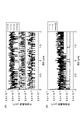
- FIG. 13 is a graph showing the relationship between the depth ( ⁇ m) in the ZnO film and the impurity concentration (cm ⁇ 3 ).
- This ZnO film is Sample 3.
- FIG. 6A shows the result of elemental analysis of H, C, Si, and Cl by irradiation with Cs + ions
- FIG. 5B shows the result of irradiation with O 2 + ions and Li
- impurities such as C, H, and Cl are at the background level and a very good quality ZnO film is formed.
- FIG. 5B the concentration of Al is increased. This is because the ZnO substrate is produced by the hydrothermal synthesis method, and Al is mixed therein. Since there is no Al in the ZnO film, it can be seen that the thickness of the ZnO film is 1.27 ⁇ m.
- FIG. 14 is a diagram showing the structure of a MOS diode for CV measurement.
- a ZnO film 2A was grown on the ZnO substrate 2, an insulating film SOG was formed on the ZnO film 2A, and an electrode E1 having a diameter of 100 ⁇ m was formed thereon using a mask.
- An electrode E2 was formed on the entire lower surface of the substrate 2.
- the thickness of the ZnO film 2A was 2.1 ⁇ m
- the thickness of the insulating film SOG was 200 nm
- the electrode material was Ti (10 nm) / Au (200 nm)
- the electrode was formed by vapor deposition.
- the insulating film SOG is a spin-on glass material, and is OCDT-12 manufactured by Tokyo Ohka Kogyo Co., Ltd., and is formed by heating at 400 ° C. for 30 minutes after the spin-on glass material is applied.
- This ZnO film is Sample 4.
- the lower surface electrode E2 was connected to the ground, the voltage applied to the upper surface electrode E1 was changed, and the capacitance (F / cm 2 ) was measured.
- FIG. 15 is a graph showing the relationship between voltage (V) and capacity per unit area (F / cm 2 ). When a positive voltage is applied, the capacity increases and is saturated to a constant value at 5 V or more. This indicates that the ZnO growth film is an n-type crystal. From this curve, the carrier concentration in the case of undoped can be calculated. In this case, the carrier concentration was 7.6 ⁇ 10 15 (cm ⁇ 3 ), which was sufficiently low and it was found that there were no large defects.
- FIG. 16 is a graph showing the relationship between the ZnCl 2 supply partial pressure (atm) and the growth rate ( ⁇ m / h).
- the partial pressure indicates the pressure in the vicinity of the substrate surface (within 1 cm from the surface).
- the control device CONT controls the amount of chlorine gas (Cl 2 ) supplied from the common gas supply source (chlorine gas supply source) G12.
- the control unit CONT controls the amount of chlorine gas supplied from the common gas supply source (chlorine gas supply source) G12, and the partial pressure of the zinc chloride gas (ZnCl 2 ) It is preferable to set 8.8 ⁇ 10 ⁇ 5 atm or more and 3.3 ⁇ 10 ⁇ 4 atm or less in the vicinity region immediately above the substrate surface. This is because the ZnO film grows sufficiently when the partial pressure of the chlorine gas is within this range.
- the control unit CONT controls the amount of chlorine gas supplied from the common gas supply source (chlorine gas supply source) G12, and the partial pressure of the zinc chloride gas is directly above the substrate surface. Is preferably set to 8.8 ⁇ 10 ⁇ 5 atm or more and 2.2 ⁇ 10 ⁇ 4 atm or less. This is because when the partial pressure of the chlorine zinc gas is within this range, the growth rate of the ZnO film is constant and stable control is possible.
- FIG. 17 is a graph (vapor pressure curve) showing the relationship between temperature T (° C.) and Zn partial pressure (atm). As the temperature T rises, Zn that is sublimated directly from the solid raw material into a gas is generated. When temperature T exceeds 330 degreeC, it turns out that Zn gasifies little by little.
- FIG. 18 is a graph showing the relationship between VI / II and the growth rate ( ⁇ m / h).
- the solid line is the theoretical curve obtained by calculation. It can be seen that the growth rate increases as the Zn partial pressure increases.
- the other conditions are the same as the formation conditions of Sample 1.
- FIG. 19 is a graph showing the relationship between ZnCl 2 supply partial pressure (atm) and Cl 2 partial pressure (atm) obtained by thermal equilibrium analysis.
- FIG. 20 is a graph showing the relationship between the ZnO film formation time (hour), the thickness ( ⁇ m), and the growth rate ( ⁇ m / h).
- the sample preparation conditions are the same as those of the sample of data D2. It can be seen that the thickness stably increases with time. That is, the growth rate is almost constant.
- FIG. 21A is a graph showing the relationship between the temperature T (° C.) and the growth rate ( ⁇ m / h).
- the sample preparation conditions are the same as those of the sample of data D2.
- VI / II 1200, Cl 2 supply amount 2.2 ⁇ 10 ⁇ 4 (atm), and substrate temperature T3 was changed. Thereby, a clear trend with respect to temperature is observed. This reaction is considered surface-controlled.
- the growth rate is a growth rate at the center of the substrate.
- FIG. 21B is a graph showing the relationship between the substrate position (cm) and the growth rate ( ⁇ m / h). As the position on the substrate becomes farther, the growth rate decreases slightly. Note that the origin of the substrate position is blowout portion of the growth areas of ZnCl 2, toward the downstream of the flow of ZnCl 2, as the position becomes large.
- 22 and 23 are tables showing the characteristics of the ZnO film for various conditions.
- the sample conditions are the same as the sample of data D2, except for various variables (temperature T3, ZnCl 2 partial pressure (near the P (ZnCl 2 ) substrate), growth time (hour), VI / II).
- the temperature T3 can be changed from 800 to 1000 ° C.
- the ZnCl 2 partial pressure can be changed from 8.8 ⁇ 10 ⁇ 5 to 3.3 ⁇ 10 ⁇ 4 (atm), and the time is 1 hour. From 9 to 9 hours, and VI / II can be changed from 20 to 2400. In these cases, it was found that a ZnO film having excellent characteristics can be obtained.
- FIG. 24 is a diagram showing a surface micrograph of the ZnO substrate surface observed with a Nomarski differential interference microscope made by Olympus.
- a Nomarski differential interference microscope made by Olympus.
- the crystal growth was attempted.
- the growth temperatures were 1000 ° C. and 600 ° C., but ZnO did not grow either on the upstream side of the substrate surface or in the middle flow.
- the substrate is sapphire, and other conditions are the same as the sample of data D2.
- FIG. 25 is a view showing a surface micrograph of the surface of the ZnO substrate observed with a Nomarski differential interference microscope manufactured by Olympus.
- a Nomarski differential interference microscope manufactured by Olympus.
- FIG. 7 In this example, in the apparatus of FIG. 7, only a single first raw material container having a constant temperature is provided and no second raw material container is provided. The crystal growth was attempted.
- the state for every case where the chlorine gas concentration is changed is shown.
- the concentration (molar concentration) of chlorine gas in the raw material container was increased from 0.2% to 10%, the growth was further suppressed, and the ZnO film was hardly grown.
- the manufacturing method of the ZnO film using the above-described manufacturing apparatus includes the chlorine gas supply source (G12, G1, G2) by the installation process of placing the substrate 2 on the installation table 3 and the control device CONT. )
- the chlorine gas supply source G12, G1, G2
- the oxygen gas from the third gas supply source (oxygen gas supply source) G3 into the reaction vessel 1
- the heating means (heaters H1, H2, H3) are controlled so that T1, the temperature T2 of the second raw material container R2, and the temperature T3 of the installation table 3 on which the substrate 2 is arranged satisfy the relationship of T1 ⁇ T2 ⁇ T3.
- a high-quality ZnO film can be manufactured as described above.
- the above-described ZnO film manufacturing apparatus includes an installation table 3 on which a substrate on which a ZnO film is to be formed, a reaction vessel that houses the installation table 3, and a solid containing Zn that communicates with the inside of the reaction vessel.
- Heating means heat H1, H2, H3, a first gas supply source for supplying a gas containing chlorine to at least the first raw material container R1, and a first gas supply source for supplying a gas containing oxygen into the reaction vessel 2 gas supply sources (the above-described third gas supply source G3), and the temperature T1 of the first raw material container R1 and the temperature T2 of the second raw material container R2 are T1 ⁇ The relationship of T2 is satisfied.
- a high-quality ZnO film can be manufactured as described above.
- the supply of the flow gas to the second raw material storage unit R2 is not performed, and the supply of the raw material disposed in the second raw material storage unit to the substrate is performed only by increasing the vapor pressure by heating, or by molecular beam.
- a structure using an epitaxy (MBE) method is also possible.
- 1 atmosphere (1 (atm): standard atmospheric pressure) is 1.01325 ⁇ 10 5 (Pa)
Landscapes
- Chemical & Material Sciences (AREA)
- General Chemical & Material Sciences (AREA)
- Chemical Kinetics & Catalysis (AREA)
- Engineering & Computer Science (AREA)
- Materials Engineering (AREA)
- Mechanical Engineering (AREA)
- Metallurgy (AREA)
- Organic Chemistry (AREA)
- Inorganic Chemistry (AREA)
- Electrochemistry (AREA)
- Chemical Vapour Deposition (AREA)
- Crystals, And After-Treatments Of Crystals (AREA)
Abstract
Description
200℃≦T1≦420℃
300℃≦T2≦600℃
600℃≦T3≦1000℃
Zn(s)+Cl2(g)→ZnCl2(g)…(1)
Zn(s)→Zn(g)…(2)
ZnCl2(g)+0.5O2(g)→ZnO(s)+Cl2(g)…(3)
Zn(g)+0.5O2(g)→ZnO(s)…(4)
P(Cl2)+P(ZnCl2)+P(Zn)+P(O2)+P(N2)=1…(5)
P0(ZnCl2)-P(ZnCl2)-P(Zn)=2P0(O2)-2P0(O2)…(6)
P0(ZnCl2)=P(ZnCl2)+P(Cl2)…(7)
・反応容器内圧力=1(atm)
・基板2:ZnO基板
・共通ガスA12:Cl2+N2
・第3ガスA3:O2+N2
・温度T1=380℃
・温度T2=400℃
・温度T3=1000℃
・ZnCl2分圧=2.2E-4(atm)
・Zn分圧=8E-6(atm)
・O2分圧=5.1E-2(atm)
・N2分圧=9.5E-1(atm)
・成長時間=60分
・VI/II=447
・反応容器内圧力=1(atm)
・基板2:ZnO基板
・共通ガスA12:Cl2+N2
・第3ガスA3:O2+N2
・温度T1=380℃
・温度T2=400℃
・温度T3=1000℃
・ZnCl2分圧=2.2E-4(atm)
・Zn分圧=8E-6(atm)
・O2分圧=1.3E-1(atm)
・N2分圧=8.7E-1(atm)
・成長時間=60分
・VI/II=1140
(A);FWHM=20(arcsec)
(B);FWHM=13(arcsec)
・反応容器内圧力=1(atm)
・基板2:ZnO基板
・共通ガスA12:Cl2+N2
・第3ガスA3:O2+N2
・温度T1=380℃
・温度T2=400℃
・温度T3=1000℃
・ZnCl2分圧=2.2E-4(atm)
・Zn分圧=8E-6(atm)
・O2分圧=1.3E-1(atm)
・N2分圧=8.7E-1(atm)
・成長時間=360分
・VI/II=1140
(A);FWHM=18(arcsec)
(B);FWHM=13(arcsec)
・反応容器内圧力=1(atm)
・基板2:ZnO基板
・共通ガスA12:Cl2+N2
・第3ガスA3:O2+N2
・温度T1=380℃
・温度T2=400℃
・温度T3=1000℃
・ZnCl2分圧=2.2E-4(atm)
・Zn分圧=8E-6(atm)
・O2分圧=1.3E-1(atm)
・N2分圧=8.7E-1(atm)
・成長時間=540分
・VI/II=1140
(A);FWHM=46(arcsec)
(B);FWHM=30(arcsec)
・反応容器内圧力=1(atm)
・基板2:ZnO基板
・共通ガスA12:Cl2+N2
・第3ガスA3:O2+N2
・温度T1=380℃
・温度T2=400℃
・温度T3=1000℃
・ZnCl2分圧=0(atm)
・Zn分圧=8E-6(atm)
・O2分圧=1.3E-1(atm)
・N2分圧=8.7E-1(atm)
・成長時間=60分
・反応容器内圧力=1(atm)
・基板2:ZnO基板
・共通ガスA12:Cl2+N2
・第3ガスA3:O2+N2
・温度T1=380℃
・温度T2=400℃
・温度T3=1000℃
・ZnCl2分圧=8.8E-5(atm)
・Zn分圧=8E-6(atm)
・O2分圧=6.6E-2(atm)
・N2分圧=9.3E-1(atm)
・成長時間=60分
・反応容器内圧力=1(atm)
・基板2:ZnO基板
・共通ガスA12:Cl2+N2
・第3ガスA3:O2+N2
・温度T1=380℃
・温度T2=400℃
・温度T3=1000℃
・ZnCl2分圧=2.2E-4(atm)
・Zn分圧=8E-6(atm)
・O2分圧=1.3E-1(atm)
・N2分圧=8.7E-1(atm)
・成長時間=60分
・反応容器内圧力=1(atm)
・基板2:ZnO基板
・共通ガスA12:Cl2+N2
・第3ガスA3:O2+N2
・温度T1=380℃
・温度T2=400℃
・温度T3=1000℃
・ZnCl2分圧=3.3E-4(atm)
・Zn分圧=8E-6(atm)
・O2分圧=2E-1(atm)
・N2分圧=8E-1(atm)
・成長時間=60分
・反応容器内圧力=1(atm)
・基板2:ZnO基板
・共通ガスA12:Cl2+N2
・第3ガスA3:O2+N2
・温度T1=380℃
・温度T2=400℃
・温度T3=1000℃
・ZnCl2分圧=4.4E-4(atm)
・Zn分圧=8E-6(atm)
・O2分圧=2.6E-1(atm)
・N2分圧=7.4E-1(atm)
・成長時間=60分
Claims (9)
- ZnO膜が形成されるべき基板が配置される設置台と、
前記設置台を収容する反応容器と、
前記反応容器内部に連通し、Znを含有する固体原料を収容する第1原料収容部と、
前記反応容器内部に連通し、Znを含有する固体原料を収容する第2原料収容部と、
前記設置台、前記第1原料収容部、及び前記第2原料収容部を加熱する加熱手段と、
少なくとも前記第1原料収容部に塩素ガスを供給する塩素ガス供給源と、
前記反応容器内に酸素ガスを供給する酸素ガス供給源と、
制御装置と、を備え、
前記制御装置は、
前記第1原料収容部の温度T1、前記第2原料収容部の温度T2、前記基板の配置された前記設置台の温度T3が、前記ZnO膜の成膜時において、T1<T2<T3の関係を満たすように、前記加熱手段を制御し、
前記塩素ガス供給源から前記第1原料収容部に供給される塩素ガスの流量を制御し、且つ、
前記酸素ガス供給源から前記反応容器内に供給される酸素ガスの流量を制御する、ことを特徴とするZnO膜の製造装置。 - 前記第2原料収容部にキャリアガスを供給するキャリアガス供給源を更に備え、前記第1原料収容部と、前記第2原料収容部とは、これらから出射されるガスの流量を互いに独立して制御することができ、且つ、前記第1原料収容部からのガスの出射方向と、前記第2原料収容部からのガスの出射方向が異なるよう、離間して配置されている、
ことを特徴とする請求項1に記載のZnO膜の製造装置。 - 前記第1原料収容部と、前記第2原料収容部とは、前記第1原料収容部を通ったガスが、前記第2原料収容部内を通るように連続している、
ことを特徴とする請求項1に記載のZnO膜の製造装置。 - 前記制御装置は、前記塩素ガス供給源から供給される塩素ガスの量を制御し、塩化亜鉛ガスの分圧を、前記基板表面の直上の近傍領域において、8.8×10⁻⁵気圧以上3.6×10⁻⁴気圧以下に設定する、
ことを特徴とする請求項1に記載のZnO膜の製造装置。 - 前記制御装置は、前記塩素ガス供給源から供給される塩素ガスの量を制御し、塩化亜鉛ガスの分圧を、前記基板表面の直上の近傍領域において、8.8×10⁻⁵気圧以上3.3×10⁻⁴気圧以下に設定する、
ことを特徴とする請求項1に記載のZnO膜の製造装置。 - 前記制御装置は、前記塩素ガス供給源から供給される塩素ガスの量を制御し、塩化亜鉛ガスの分圧を、前記基板表面の直上の近傍領域において、8.8×10⁻⁵気圧以上2.2×10⁻⁴気圧以下に設定する、
ことを特徴とする請求項1に記載のZnO膜の製造装置。 - 前記第1原料収容部と、前記第2原料収容部とは、前記第1原料収容部を通ったガスが、前記第2原料収容部内を通るように連続しており、且つ、前記第1及び2原料収容部の底面は、この底面よりも上方に位置する水平面からの深さが、前記第2原料収容部のガス出射口に向かうにしたがって深くなるように、傾斜していることを特徴とする請求項1に記載のZnO膜の製造装置。
- 請求項1に記載のZnO膜の製造装置を用いたZnO膜の製造方法において、
前記設置台に前記基板を配置する設置工程と、
前記制御装置によって、前記塩素ガス供給源から前記第1原料収容部に塩素ガスを供給し、且つ、前記酸素ガス供給源から前記反応容器内に酸素ガスを供給しつつ、前記第1原料収容部の温度T1、前記第2原料収容部の温度T2、前記基板の配置された前記設置台の温度T3が、T1<T2<T3の関係を満たすように、前記加熱手段を制御する成膜工程と、
を備えることを特徴とするZnO膜の製造方法。 - ZnO膜が形成されるべき基板が配置される設置台と、
前記設置台を収容する反応容器と、
前記反応容器内部に連通し、Znを含有する固体原料を収容する第1原料収容部と、
前記反応容器内部に連通し、Znを含有する固体原料を収容する第2原料収容部と、
前記第1原料収容部、及び前記第2原料収容部を加熱する加熱手段と、
少なくとも前記第1原料収容部に塩素を含むガスを供給する第1のガス供給源と、
前記反応容器内に酸素を含むガスを供給する第2のガス供給源と、を備え、
前記第1原料収容部の温度T1、前記第2原料収容部の温度T2が、前記ZnO膜の成膜時において、T1<T2の関係を満たすことを特徴とするZnO膜の製造装置。
Priority Applications (2)
| Application Number | Priority Date | Filing Date | Title |
|---|---|---|---|
| US14/417,196 US9611545B2 (en) | 2012-07-27 | 2013-06-19 | ZnO film production system and production method using ZnO film production system having heating units and control device |
| KR1020157001841A KR20150036173A (ko) | 2012-07-27 | 2013-06-19 | ZnO막의 제조 장치 및 제조 방법 |
Applications Claiming Priority (2)
| Application Number | Priority Date | Filing Date | Title |
|---|---|---|---|
| JP2012-167481 | 2012-07-27 | ||
| JP2012167481A JP5943345B2 (ja) | 2012-07-27 | 2012-07-27 | ZnO膜の製造装置及び製造方法 |
Publications (1)
| Publication Number | Publication Date |
|---|---|
| WO2014017229A1 true WO2014017229A1 (ja) | 2014-01-30 |
Family
ID=49997046
Family Applications (1)
| Application Number | Title | Priority Date | Filing Date |
|---|---|---|---|
| PCT/JP2013/066863 Ceased WO2014017229A1 (ja) | 2012-07-27 | 2013-06-19 | ZnO膜の製造装置及び製造方法 |
Country Status (4)
| Country | Link |
|---|---|
| US (1) | US9611545B2 (ja) |
| JP (1) | JP5943345B2 (ja) |
| KR (1) | KR20150036173A (ja) |
| WO (1) | WO2014017229A1 (ja) |
Families Citing this family (1)
| Publication number | Priority date | Publication date | Assignee | Title |
|---|---|---|---|---|
| JP2714791B2 (ja) | 1987-07-16 | 1998-02-16 | 株式会社ブリヂストン | 重心測定装置 |
Citations (2)
| Publication number | Priority date | Publication date | Assignee | Title |
|---|---|---|---|---|
| JP2003324070A (ja) * | 2002-04-30 | 2003-11-14 | Suzuki Motor Corp | 薄膜の製造方法およびその装置 |
| JP2008243987A (ja) * | 2007-03-26 | 2008-10-09 | Tokyo Univ Of Agriculture & Technology | 酸化亜鉛系半導体の製造方法及び酸化亜鉛系半導体の製造装置 |
Family Cites Families (27)
| Publication number | Priority date | Publication date | Assignee | Title |
|---|---|---|---|---|
| FR2320774A1 (fr) * | 1974-01-10 | 1977-03-11 | Radiotechnique Compelec | Procede et dispositif de depot de materiau dope |
| JP2587623B2 (ja) * | 1986-11-22 | 1997-03-05 | 新技術事業団 | 化合物半導体のエピタキシヤル結晶成長方法 |
| JPH03218621A (ja) * | 1989-11-30 | 1991-09-26 | Toshiba Corp | 薄膜の選択成長方法及び薄膜の選択成長装置 |
| US5225366A (en) * | 1990-06-22 | 1993-07-06 | The United States Of America As Represented By The Secretary Of The Navy | Apparatus for and a method of growing thin films of elemental semiconductors |
| US5750188A (en) * | 1996-08-29 | 1998-05-12 | Motorola, Inc. | Method for forming a thin film of a non-stoichiometric metal oxide |
| US6555452B2 (en) * | 1997-11-18 | 2003-04-29 | Technologies And Devices International, Inc. | Method for growing p-type III-V compound material utilizing HVPE techniques |
| JP2001270799A (ja) | 2000-03-27 | 2001-10-02 | Toyo Ink Mfg Co Ltd | 酸化亜鉛薄膜およびその製造方法 |
| US6573164B2 (en) * | 2001-03-30 | 2003-06-03 | Technologies And Devices International, Inc. | Method of epitaxially growing device structures with sharp layer interfaces utilizing HVPE |
| US6936357B2 (en) * | 2001-07-06 | 2005-08-30 | Technologies And Devices International, Inc. | Bulk GaN and ALGaN single crystals |
| US6613143B1 (en) * | 2001-07-06 | 2003-09-02 | Technologies And Devices International, Inc. | Method for fabricating bulk GaN single crystals |
| US7501023B2 (en) * | 2001-07-06 | 2009-03-10 | Technologies And Devices, International, Inc. | Method and apparatus for fabricating crack-free Group III nitride semiconductor materials |
| US6846516B2 (en) * | 2002-04-08 | 2005-01-25 | Applied Materials, Inc. | Multiple precursor cyclical deposition system |
| US20040142558A1 (en) * | 2002-12-05 | 2004-07-22 | Granneman Ernst H. A. | Apparatus and method for atomic layer deposition on substrates |
| US8647435B1 (en) * | 2006-10-11 | 2014-02-11 | Ostendo Technologies, Inc. | HVPE apparatus and methods for growth of p-type single crystal group III nitride materials |
| US8129208B2 (en) * | 2007-02-07 | 2012-03-06 | Tokuyama Corporation | n-Type conductive aluminum nitride semiconductor crystal and manufacturing method thereof |
| JP4537434B2 (ja) * | 2007-08-31 | 2010-09-01 | 株式会社日立製作所 | 酸化亜鉛薄膜、及びそれを用いた透明導電膜、及び表示素子 |
| EP2297778A1 (en) * | 2008-05-23 | 2011-03-23 | Semiconductor Energy Laboratory Co, Ltd. | Semiconductor device |
| US8822263B2 (en) * | 2008-06-30 | 2014-09-02 | National University Corporation Tokyo University Of Agriculture And Technology | Epitaxial growth method of a zinc oxide based semiconductor layer, epitaxial crystal structure, epitaxial crystal growth apparatus, and semiconductor device |
| WO2011043414A1 (ja) * | 2009-10-09 | 2011-04-14 | 国立大学法人東北大学 | 薄膜とその形成方法、及びその薄膜を備えた半導体発光素子 |
| US20120064665A1 (en) * | 2010-09-13 | 2012-03-15 | Semiconductor Energy Laboratory Co., Ltd. | Deposition apparatus, apparatus for successive deposition, and method for manufacturing semiconductor device |
| JP2014507794A (ja) * | 2010-12-30 | 2014-03-27 | ジュスン エンジニアリング カンパニー リミテッド | 薄膜トランジスタ及びその製造方法 |
| KR101357595B1 (ko) * | 2011-11-17 | 2014-02-05 | (주)디엔에프 | 알킬 징크 할라이드 산화아연 전구체 및 이를 이용한 산화아연계 박막 증착방법 |
| CN104284776B (zh) * | 2012-05-14 | 2016-01-06 | 柯尼卡美能达株式会社 | 气体阻隔性膜、气体阻隔性膜的制造方法及电子设备 |
| TW201415654A (zh) * | 2012-10-05 | 2014-04-16 | 行政院原子能委員會核能研究所 | 薄膜太陽能電池吸收層之製造方法 |
| KR20140046617A (ko) * | 2012-10-09 | 2014-04-21 | 삼성코닝정밀소재 주식회사 | 산화아연 전구체 및 이를 이용한 산화아연계 박막 증착방법 |
| JP6344688B2 (ja) * | 2013-06-10 | 2018-06-20 | 株式会社トクヤマ | アルミニウム系iii族窒化物単結晶の製造方法 |
| US20150225845A1 (en) * | 2014-02-12 | 2015-08-13 | Electronics And Telecommunications Research Institute | Method for forming metal oxide thin film and device for printing metal oxide thin film |
-
2012
- 2012-07-27 JP JP2012167481A patent/JP5943345B2/ja not_active Expired - Fee Related
-
2013
- 2013-06-19 WO PCT/JP2013/066863 patent/WO2014017229A1/ja not_active Ceased
- 2013-06-19 US US14/417,196 patent/US9611545B2/en not_active Expired - Fee Related
- 2013-06-19 KR KR1020157001841A patent/KR20150036173A/ko not_active Ceased
Patent Citations (2)
| Publication number | Priority date | Publication date | Assignee | Title |
|---|---|---|---|---|
| JP2003324070A (ja) * | 2002-04-30 | 2003-11-14 | Suzuki Motor Corp | 薄膜の製造方法およびその装置 |
| JP2008243987A (ja) * | 2007-03-26 | 2008-10-09 | Tokyo Univ Of Agriculture & Technology | 酸化亜鉛系半導体の製造方法及び酸化亜鉛系半導体の製造装置 |
Non-Patent Citations (1)
| Title |
|---|
| NAOYUKI TAKAHASHI, ET AL. ET AL.: "Atmospheric pressure vapor-phase growth of ZnO using a chloride source", JOURNAL OF CRYSTAL GROWTH, vol. 209, 2000, pages 822 - 827 * |
Also Published As
| Publication number | Publication date |
|---|---|
| JP2014025123A (ja) | 2014-02-06 |
| US9611545B2 (en) | 2017-04-04 |
| US20150225846A1 (en) | 2015-08-13 |
| KR20150036173A (ko) | 2015-04-07 |
| JP5943345B2 (ja) | 2016-07-05 |
Similar Documents
| Publication | Publication Date | Title |
|---|---|---|
| JP6311834B2 (ja) | 窒化物半導体基板の製造方法 | |
| US7279040B1 (en) | Method and apparatus for zinc oxide single crystal boule growth | |
| JP5787324B2 (ja) | 三塩化ガリウムガスの製造方法及び窒化物半導体結晶の製造方法 | |
| JP5197283B2 (ja) | 窒化アルミニウム単結晶基板、積層体、およびこれらの製造方法 | |
| WO2015037232A1 (ja) | 窒化物半導体結晶、製造方法および製造装置 | |
| JP4199921B2 (ja) | 炭化珪素単結晶を製造する方法および装置 | |
| WO2008108381A1 (ja) | Iii族窒化物結晶の製造方法 | |
| CN103124811A (zh) | 生长GaN晶体的方法和GaN晶体衬底 | |
| WO2008096884A1 (ja) | n型導電性窒化アルミニウム半導体結晶及びその製造方法 | |
| JP5186733B2 (ja) | AlN結晶の成長方法 | |
| CN101283122A (zh) | 氧化锌晶体,它的生长方法和发光器件的生产方法 | |
| JP5943345B2 (ja) | ZnO膜の製造装置及び製造方法 | |
| JP7796020B2 (ja) | 高品質なヘテロエピタキシャル単斜晶ガリウム酸化物結晶の成長方法 | |
| Yamaguchi et al. | Growth of Highly Crystalline GaN at High Growth Rate by Trihalide Vapor‐Phase Epitaxy | |
| Torrison et al. | Morphological and optical properties of Si nanostructures imbedded in SiO 2 and Si 3 N 4 films grown by single source chemical vapor deposition | |
| JP3991815B2 (ja) | 酸化亜鉛結晶膜の育成方法 | |
| JP2020189779A (ja) | 炭化珪素の製造方法 | |
| JP2007137714A (ja) | 単結晶の製造方法及び単結晶の製造装置 | |
| JP2007145679A (ja) | 窒化アルミニウム単結晶の製造装置及びその製造方法 | |
| WO2025028325A1 (ja) | 窒化ガリウムの製造方法、窒化ガリウムの気相成長装置および窒化ガリウム基板 | |
| JP5988041B2 (ja) | ZnO含有膜成長用の原料供給源、ZnO含有膜の製造装置、製造方法及びZnO含有膜を含む発光素子 | |
| CN110578170B (zh) | ScAlMgO4单晶及器件 | |
| JPH01173708A (ja) | 半導体素子 | |
| JP2008198857A (ja) | 半導体製造装置 |
Legal Events
| Date | Code | Title | Description |
|---|---|---|---|
| 121 | Ep: the epo has been informed by wipo that ep was designated in this application |
Ref document number: 13823678 Country of ref document: EP Kind code of ref document: A1 |
|
| ENP | Entry into the national phase |
Ref document number: 20157001841 Country of ref document: KR Kind code of ref document: A |
|
| WWE | Wipo information: entry into national phase |
Ref document number: 14417196 Country of ref document: US |
|
| NENP | Non-entry into the national phase |
Ref country code: DE |
|
| 122 | Ep: pct application non-entry in european phase |
Ref document number: 13823678 Country of ref document: EP Kind code of ref document: A1 |