WO2014013754A1 - アンギュラ玉軸受及び組合せ軸受 - Google Patents
アンギュラ玉軸受及び組合せ軸受 Download PDFInfo
- Publication number
- WO2014013754A1 WO2014013754A1 PCT/JP2013/057263 JP2013057263W WO2014013754A1 WO 2014013754 A1 WO2014013754 A1 WO 2014013754A1 JP 2013057263 W JP2013057263 W JP 2013057263W WO 2014013754 A1 WO2014013754 A1 WO 2014013754A1
- Authority
- WO
- WIPO (PCT)
- Prior art keywords
- outer ring
- ring
- ball bearing
- axial direction
- raceway surface
- Prior art date
- Legal status (The legal status is an assumption and is not a legal conclusion. Google has not performed a legal analysis and makes no representation as to the accuracy of the status listed.)
- Ceased
Links
Images

Classifications
-
- F—MECHANICAL ENGINEERING; LIGHTING; HEATING; WEAPONS; BLASTING
- F16—ENGINEERING ELEMENTS AND UNITS; GENERAL MEASURES FOR PRODUCING AND MAINTAINING EFFECTIVE FUNCTIONING OF MACHINES OR INSTALLATIONS; THERMAL INSULATION IN GENERAL
- F16C—SHAFTS; FLEXIBLE SHAFTS; ELEMENTS OR CRANKSHAFT MECHANISMS; ROTARY BODIES OTHER THAN GEARING ELEMENTS; BEARINGS
- F16C19/00—Bearings with rolling contact, for exclusively rotary movement
- F16C19/54—Systems consisting of a plurality of bearings with rolling friction
- F16C19/541—Systems consisting of juxtaposed rolling bearings including at least one angular contact bearing
- F16C19/542—Systems consisting of juxtaposed rolling bearings including at least one angular contact bearing with two rolling bearings with angular contact
- F16C19/543—Systems consisting of juxtaposed rolling bearings including at least one angular contact bearing with two rolling bearings with angular contact in O-arrangement
-
- F—MECHANICAL ENGINEERING; LIGHTING; HEATING; WEAPONS; BLASTING
- F16—ENGINEERING ELEMENTS AND UNITS; GENERAL MEASURES FOR PRODUCING AND MAINTAINING EFFECTIVE FUNCTIONING OF MACHINES OR INSTALLATIONS; THERMAL INSULATION IN GENERAL
- F16C—SHAFTS; FLEXIBLE SHAFTS; ELEMENTS OR CRANKSHAFT MECHANISMS; ROTARY BODIES OTHER THAN GEARING ELEMENTS; BEARINGS
- F16C19/00—Bearings with rolling contact, for exclusively rotary movement
- F16C19/02—Bearings with rolling contact, for exclusively rotary movement with bearing balls essentially of the same size in one or more circular rows
- F16C19/14—Bearings with rolling contact, for exclusively rotary movement with bearing balls essentially of the same size in one or more circular rows for both radial and axial load
- F16C19/18—Bearings with rolling contact, for exclusively rotary movement with bearing balls essentially of the same size in one or more circular rows for both radial and axial load with two or more rows of balls
- F16C19/181—Bearings with rolling contact, for exclusively rotary movement with bearing balls essentially of the same size in one or more circular rows for both radial and axial load with two or more rows of balls with angular contact
- F16C19/183—Bearings with rolling contact, for exclusively rotary movement with bearing balls essentially of the same size in one or more circular rows for both radial and axial load with two or more rows of balls with angular contact with two rows at opposite angles
- F16C19/184—Bearings with rolling contact, for exclusively rotary movement with bearing balls essentially of the same size in one or more circular rows for both radial and axial load with two or more rows of balls with angular contact with two rows at opposite angles in O-arrangement
-
- F—MECHANICAL ENGINEERING; LIGHTING; HEATING; WEAPONS; BLASTING
- F16—ENGINEERING ELEMENTS AND UNITS; GENERAL MEASURES FOR PRODUCING AND MAINTAINING EFFECTIVE FUNCTIONING OF MACHINES OR INSTALLATIONS; THERMAL INSULATION IN GENERAL
- F16C—SHAFTS; FLEXIBLE SHAFTS; ELEMENTS OR CRANKSHAFT MECHANISMS; ROTARY BODIES OTHER THAN GEARING ELEMENTS; BEARINGS
- F16C33/00—Parts of bearings; Special methods for making bearings or parts thereof
- F16C33/30—Parts of ball or roller bearings
- F16C33/58—Raceways; Race rings
- F16C33/583—Details of specific parts of races
- F16C33/586—Details of specific parts of races outside the space between the races, e.g. end faces or bore of inner ring
-
- F—MECHANICAL ENGINEERING; LIGHTING; HEATING; WEAPONS; BLASTING
- F16—ENGINEERING ELEMENTS AND UNITS; GENERAL MEASURES FOR PRODUCING AND MAINTAINING EFFECTIVE FUNCTIONING OF MACHINES OR INSTALLATIONS; THERMAL INSULATION IN GENERAL
- F16C—SHAFTS; FLEXIBLE SHAFTS; ELEMENTS OR CRANKSHAFT MECHANISMS; ROTARY BODIES OTHER THAN GEARING ELEMENTS; BEARINGS
- F16C33/00—Parts of bearings; Special methods for making bearings or parts thereof
- F16C33/30—Parts of ball or roller bearings
- F16C33/66—Special parts or details in view of lubrication
- F16C33/6603—Special parts or details in view of lubrication with grease as lubricant
- F16C33/6607—Retaining the grease in or near the bearing
-
- F—MECHANICAL ENGINEERING; LIGHTING; HEATING; WEAPONS; BLASTING
- F16—ENGINEERING ELEMENTS AND UNITS; GENERAL MEASURES FOR PRODUCING AND MAINTAINING EFFECTIVE FUNCTIONING OF MACHINES OR INSTALLATIONS; THERMAL INSULATION IN GENERAL
- F16C—SHAFTS; FLEXIBLE SHAFTS; ELEMENTS OR CRANKSHAFT MECHANISMS; ROTARY BODIES OTHER THAN GEARING ELEMENTS; BEARINGS
- F16C33/00—Parts of bearings; Special methods for making bearings or parts thereof
- F16C33/72—Sealings
- F16C33/76—Sealings of ball or roller bearings
- F16C33/78—Sealings of ball or roller bearings with a diaphragm, disc, or ring, with or without resilient members
- F16C33/784—Sealings of ball or roller bearings with a diaphragm, disc, or ring, with or without resilient members mounted to a groove in the inner surface of the outer race and extending toward the inner race
- F16C33/7843—Sealings of ball or roller bearings with a diaphragm, disc, or ring, with or without resilient members mounted to a groove in the inner surface of the outer race and extending toward the inner race with a single annular sealing disc
- F16C33/7846—Sealings of ball or roller bearings with a diaphragm, disc, or ring, with or without resilient members mounted to a groove in the inner surface of the outer race and extending toward the inner race with a single annular sealing disc with a gap between the annular disc and the inner race
-
- F—MECHANICAL ENGINEERING; LIGHTING; HEATING; WEAPONS; BLASTING
- F16—ENGINEERING ELEMENTS AND UNITS; GENERAL MEASURES FOR PRODUCING AND MAINTAINING EFFECTIVE FUNCTIONING OF MACHINES OR INSTALLATIONS; THERMAL INSULATION IN GENERAL
- F16C—SHAFTS; FLEXIBLE SHAFTS; ELEMENTS OR CRANKSHAFT MECHANISMS; ROTARY BODIES OTHER THAN GEARING ELEMENTS; BEARINGS
- F16C33/00—Parts of bearings; Special methods for making bearings or parts thereof
- F16C33/72—Sealings
- F16C33/76—Sealings of ball or roller bearings
- F16C33/78—Sealings of ball or roller bearings with a diaphragm, disc, or ring, with or without resilient members
- F16C33/784—Sealings of ball or roller bearings with a diaphragm, disc, or ring, with or without resilient members mounted to a groove in the inner surface of the outer race and extending toward the inner race
- F16C33/7843—Sealings of ball or roller bearings with a diaphragm, disc, or ring, with or without resilient members mounted to a groove in the inner surface of the outer race and extending toward the inner race with a single annular sealing disc
- F16C33/7853—Sealings of ball or roller bearings with a diaphragm, disc, or ring, with or without resilient members mounted to a groove in the inner surface of the outer race and extending toward the inner race with a single annular sealing disc with one or more sealing lips to contact the inner race
- F16C33/7856—Sealings of ball or roller bearings with a diaphragm, disc, or ring, with or without resilient members mounted to a groove in the inner surface of the outer race and extending toward the inner race with a single annular sealing disc with one or more sealing lips to contact the inner race with a single sealing lip
-
- F—MECHANICAL ENGINEERING; LIGHTING; HEATING; WEAPONS; BLASTING
- F16—ENGINEERING ELEMENTS AND UNITS; GENERAL MEASURES FOR PRODUCING AND MAINTAINING EFFECTIVE FUNCTIONING OF MACHINES OR INSTALLATIONS; THERMAL INSULATION IN GENERAL
- F16C—SHAFTS; FLEXIBLE SHAFTS; ELEMENTS OR CRANKSHAFT MECHANISMS; ROTARY BODIES OTHER THAN GEARING ELEMENTS; BEARINGS
- F16C33/00—Parts of bearings; Special methods for making bearings or parts thereof
- F16C33/72—Sealings
- F16C33/76—Sealings of ball or roller bearings
- F16C33/78—Sealings of ball or roller bearings with a diaphragm, disc, or ring, with or without resilient members
- F16C33/7886—Sealings of ball or roller bearings with a diaphragm, disc, or ring, with or without resilient members mounted outside the gap between the inner and outer races, e.g. sealing rings mounted to an end face or outer surface of a race
-
- F—MECHANICAL ENGINEERING; LIGHTING; HEATING; WEAPONS; BLASTING
- F16—ENGINEERING ELEMENTS AND UNITS; GENERAL MEASURES FOR PRODUCING AND MAINTAINING EFFECTIVE FUNCTIONING OF MACHINES OR INSTALLATIONS; THERMAL INSULATION IN GENERAL
- F16C—SHAFTS; FLEXIBLE SHAFTS; ELEMENTS OR CRANKSHAFT MECHANISMS; ROTARY BODIES OTHER THAN GEARING ELEMENTS; BEARINGS
- F16C19/00—Bearings with rolling contact, for exclusively rotary movement
- F16C19/02—Bearings with rolling contact, for exclusively rotary movement with bearing balls essentially of the same size in one or more circular rows
- F16C19/14—Bearings with rolling contact, for exclusively rotary movement with bearing balls essentially of the same size in one or more circular rows for both radial and axial load
- F16C19/16—Bearings with rolling contact, for exclusively rotary movement with bearing balls essentially of the same size in one or more circular rows for both radial and axial load with a single row of balls
- F16C19/163—Bearings with rolling contact, for exclusively rotary movement with bearing balls essentially of the same size in one or more circular rows for both radial and axial load with a single row of balls with angular contact
Definitions
- the present invention relates to an angular ball bearing and a combined bearing.
- a grease-sealed bearing is suitable for a compact machine design because of its simple lubricating structure.
- a deep groove ball bearing has been used for a long time, and an angular ball bearing has been used as a rotating body support device in recent years.
- the life of grease sealed in bearings tends to be reduced, and countermeasures have been required.
- the outer diameter of the shaft is desirably equal to or greater than that of the conventional product.
- the bearings used in industrial machines are thin-walled products, for example, ISO diameter series 0 or 9, so that the outer diameter of the rolling elements is also reduced, and the load capacity is disadvantageous.
- a typical example is a machine tool built-in spindle of a machine tool, and the same applies to a centrifugal separator, a textile machine, and the like.
- an increase in the ratio “L / d” between the length L and the diameter d of the shaft 100 means a decrease in shaft rigidity, and shaft bending during use tends to occur.
- What is supported one shaft 100 is supported by three bearings 110) is known.
- the increase in “L / d” is disadvantageous in maintaining accuracy of the machine parts and in assembling accuracy, and acts on the bearing 110 as misalignment (inclination and displacement of the core of the inner and outer rings). When three points are supported, this misalignment tends to easily affect the bearing 110.
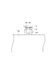
- the angular ball bearing has a contact angle unlike the deep groove ball bearing (see FIG. 8), and the internal stress generated by the load support shifts in the axial direction (in FIG. 7 and FIG. The generation position is indicated by A.), and the thickness of the side of the raceway surface is required.
- the angular ball bearing used for industrial machinery needs to be a thin product as described above, if an O-ring groove or a seal groove is provided in the outer ring, the wall thickness is further reduced and the strength is reduced. .
- the present invention has been made in view of the above-described problems, and an object of the present invention is to provide a long-life angular contact ball bearing and a combination bearing used in grease lubrication.
- the above object of the present invention can be achieved by the following constitution. (1) an inner ring having an inner ring raceway surface formed on the outer periphery; An outer ring having an outer ring raceway surface formed on the inner periphery; A plurality of balls incorporated with a contact angle between the inner ring raceway surface and the outer ring raceway surface; An angular ball bearing having The axial width of the outer ring is greater than 0 in the width series in ISO, The outer periphery of the inner ring has an inner ring shoulder formed on one axial side with respect to the inner ring raceway surface, and a counter bore formed on the other axial side.
- An inner peripheral portion of the outer ring includes a pair of outer ring shoulder portions formed on both sides in the axial direction across the outer ring raceway surface, and a seal member on one axial side with respect to the outer ring shoulder portion facing the inner ring shoulder portion. And a seal groove formed to fix another seal member on the other side in the axial direction with respect to the shoulder portion of the outer ring facing the counter bore. And Angular contact ball bearings that are lubricated internally with grease. (2) The angular ball bearing according to (1), wherein an axial width of the outer ring is larger than 1 in a width series in ISO.
- the axial width of the outer ring is set to be greater than 0 in the width series in ISO, the bearing internal space can be increased and the amount of grease filled can be increased. It is possible to extend the grease life. Furthermore, since the outer ring is a wide product, it is possible to obtain a space for providing a seal groove for fixing the seal member on both axial sides of the inner peripheral portion.
- the axial width of the outer ring is set to be greater than 1 in the width series in ISO, the amount of grease can be further increased and the outer ring shoulder and seal groove are formed. Space to do.
- the O-ring groove for fixing the O-ring is provided in the outer ring which is a wide product, so that the design becomes easy.
- the outer ring formed as a wide product is provided with the seal groove, the O-ring groove, and the outer ring raceway surface being offset in order from one side in the axial direction. Even in the case of a thin product, it is possible to suppress a decrease in strength due to the provision of the seal groove, the O-ring groove, and the outer ring raceway surface. In particular, since the O-ring groove is provided between the seal groove and the outer ring raceway surface in the axial direction, it is possible to prevent the outer ring from extending more than necessary in the axial direction.
- the outer ring formed as a wide product is provided with the O-ring groove, the seal groove, and the outer ring raceway surface being offset from the one side in the axial direction. Even in the case of a thin product, it is possible to suppress a decrease in strength due to the provision of the O-ring groove, the seal groove, and the outer ring raceway surface.
- the counter bore can be shortened and the wall thickness necessary for maintaining the strength is ensured. Is possible.
- the one end surface in the axial direction of the inner ring and the one end surface in the axial direction of the outer ring are substantially at the same position. It is possible to prevent the ball from riding on the counter bore of the inner ring when placed on a board or the like.
- the counter bore can be shortened and is necessary for maintaining the strength. It is possible to ensure the wall thickness.
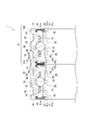
- a rotating body support device 1 that rotatably supports a rotating shaft of an industrial machine (not shown) such as a machine tool on a housing includes a pair of single-row angular ball bearings 10A and 10B as shown in FIG. It is composed of a combination bearing 10 configured by combining two back surfaces so that the contact angle substantially represents a letter C.
- Each of the single-row angular ball bearings 10A and 10B is, for example, a thin product of ISO diameter series 0 or 9, and an inner ring 20 having an inner ring raceway surface 22 formed on the outer peripheral portion and an outer ring raceway surface 32 formed on the inner peripheral portion.
- a plurality of balls 40 incorporated with a contact angle between the outer ring raceway surface 22 and the inner ring raceway surface 22 and the outer ring raceway surface 32, and a cage 50 that holds the plurality of balls 40 in a rollable manner. .
- the cage 50 is made of mild steel, copper alloy, resin or the like, and a resin that is lightweight and has excellent wear resistance is particularly suitable when operating at high speed under grease lubrication.
- a resin material a cotton cloth impregnated with a phenol resin and thermally cured is available.
- Polyamide is a thermoplastic resin that can be mass-produced at low cost, and so-called super engineering plastics such as polyphenylene sulfide and polyetheretherketone are suitable in terms of heat resistance, chemical resistance, and high strength. Furthermore, glass fibers and carbon fibers are mixed with these thermoplastic resins, and the strength increases.
- the outer periphery of the inner ring 20 has an inner ring shoulder 24 formed on the outer side in the axial direction (one side in the axial direction) with respect to the inner ring raceway surface 22, and a counter bore 26 formed on the inner side in the axial direction (the other side in the axial direction).
- the inner peripheral portion of the outer ring 30 includes a pair of first and second outer ring shoulder portions 34 and 35 formed on both sides in the axial direction across the outer ring raceway surface 32, and a first outer ring that radially faces the inner ring shoulder portion 24.
- a first seal groove 36 formed to fix the first seal member 61 on the outer side in the axial direction with respect to the shoulder portion 34, and an axial direction with respect to the second outer ring shoulder portion 35 diametrically opposed to the counter bore 26.
- a second seal groove 37 formed to fix the second seal member 62 inside.
- the first and second seal members 61, 62 are made of metal cores 61a, 62a and elastic bodies 61b, 62b covering the cores 61a, 62a. Lips 61c, 62c are provided at the ends of the elastic bodies 61b, 62b. Is formed.
- the lip 61c of the first seal member 61 is opposed to the recess 28 formed at the axially outer end of the outer periphery of the inner ring 20 with a slight gap, and the lip 62c of the second seal member 62 is By facing the counter bore 26 at the outer peripheral portion in the radial direction through a slight gap, these gaps constitute a labyrinth, so that the grease sealed inside the bearing is sealed, and from the outside to the inside of the bearing Intrusion of foreign matter is prevented.
- the axial width of the outer ring 30 is formed so as to be larger than 0 in the width series in ISO, more preferably greater than 1 in the width series in ISO, and is larger than the axial width of the inner ring 20. Is set. Therefore, the outer ring 30 has first and second extending portions 30a and 30b extending toward both axial sides from the inner ring 20, and the outer circumferences of the first and second extending portions 30a and 30b.
- the part is provided with first and second O-ring grooves 38 and 39 for fixing an O-ring (not shown).
- the inclination with the housing is buffered by the O-ring, so misalignment (inclination of the core of the inner and outer rings Deviation) can be suppressed.
- the elastic bodies 61b, 62b and O-rings of the first and second seal members 61, 62 are usually made of rubber, and nitrile butadiene is generally used, and an additive is added to improve heat resistance and chemical resistance. When it contains, it is suitable. If further high temperature properties are required, acrylic rubber and fluorine rubber are used. Employed especially when the atmosphere is chemically special. Typical examples are cutting water for machine tools, coolant for power engines, and petrochemical gases.
- the outer ring 30 is provided with the first O-ring groove 38, the first seal groove 36, the outer ring raceway surface 32, the second seal groove 37, and the second O-ring groove 39 offset from the outside in the axial direction. And are arranged so as not to overlap each other.
- the pair of outer rings 30 and 30 are positioned in the axial direction by abutting each other, and the pair of inner rings 20 and 20 is paired with the pair of second extending portions 30b and 30b between the pair of inner rings 20 and 20. Is positioned in the axial direction by arranging a spacer 70 having substantially the same width.
- the outer diameter dimension of the spacer 70 is set slightly smaller than the inner diameter dimension of the adjacent seal member 62. Thereby, even if the spacer 70 and the seal member 62 approach each other due to deformation in the bearing due to a manufacturing error or a load load, interference does not occur, and occurrence of abnormal loss (rotational torque) as a rotating body can be prevented. If there is no such concern, the outer diameter of the spacer 70 is made larger than the inner diameter of the seal member 62, so that the cross-sectional area of the spacer 70 increases and the inner ring 20 side is tightened and fixed with a nut or the like.
- the outer diameter of the spacer 70 is made smaller than the inner diameter of the seal member 62 in the vicinity of the seal member 62 (outside in the axial direction), and the center side of the spacer 70 (inner side in the axial direction) is sealed.
- the inner diameter of the member 62 may be equal to or larger than the inner diameter
- the outer peripheral surface of the spacer 70 may have a cylindrical shape with several stages.
- the combination bearing 10 configured by combining the single-row angular ball bearings 10A and 10B on the back surface has been described.
- the combination bearing 10 may be configured by combining the single-row angular ball bearings 10A and 10B on the front surface. I do not care. Further, the single row angular ball bearings 10A and 10B may be used alone without being combined with each other.
- the axial width of the outer ring 30 is set to 0, more preferably greater than 1 in the width series in ISO. Can be increased, the amount of grease filled can be increased, and the grease life can be extended. Furthermore, since the outer ring 30 becomes a wide product, a space for providing the first and second seal grooves 36 and 37 for fixing the first and second seal members 61 and 62 on both sides in the axial direction of the inner peripheral portion thereof is provided. It is possible to obtain.
- first and second O-ring grooves 38 and 39 for fixing the O-ring to the outer ring 30 which is a wide product are provided, the design becomes easy.
- the outer ring 30 that is a wide product is offset by a first O-ring groove 38, a first seal groove 36, an outer ring raceway surface 32, a second seal groove 37, and a second O-ring groove 39 in order from one side in the axial direction. Therefore, even if the outer ring 30 is a thin product, the first and second seal grooves 36 and 37, the first and second O-ring grooves 38 and 39, and the outer ring raceway surface 32 are provided. It is possible to suppress a decrease in strength due to this.
- first seal member 61 and the second seal member 62 fixed to the outer ring 30 face the outer peripheral portion of the inner ring 20, the sealing performance is maintained even when the angular ball bearings 10A and 10B are handled alone. It is possible to prevent foreign matter from entering from the outside.
- the counter bore 26 can be shortened, and the wall thickness necessary for maintaining the strength can be ensured.
- the spacer 70 is disposed between the single-row angular ball bearings 10A and 10B in the axial direction of the inner rings 20 and 20, the counter bores 26 and 26 can be shortened, and the meat required for maintaining the strength can be obtained. It is possible to ensure the thickness.
- the combination bearing of the present embodiment has the same basic configuration as that of the combination bearing of the first embodiment. Therefore, the same or corresponding parts are denoted by the same reference numerals, and the description thereof is omitted or simplified. The explanation will be focused on.
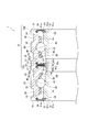
- the single-row angular contact ball bearings 10 ⁇ / b> A and 10 ⁇ / b> B of the present embodiment each have an inner ring 20 and an outer ring 30 that have substantially the same axial width, and a pair of inner rings 20, 20 and a pair of The outer rings 30 are positioned in the axial direction by abutting each other.
- the axially outer side surface 21 of the inner ring 20 and the axially outer side surface 31 of the outer ring 30 are substantially in the same position, so-called “flat”. Therefore, it is possible to prevent the balls 40 from getting on the counter bore 26 of the inner ring 20 when the axially outer sides of the single row angular ball bearings 10A and 10B are placed on a surface plate or the like.
- the first and second O-ring grooves 38 and 39 are provided between the outer ring raceway surface 32 and the first and second seal grooves 36 and 37 in the axial direction, respectively.
- the outer ring 30 is provided on the outer peripheral portion of the outer ring 30 so as to overlap the shoulder parts 34 and 35 in the axial direction. That is, the outer ring 30 is provided with a first seal groove 36, a first O-ring groove 38, an outer ring raceway surface 32, a second O-ring groove 39, and a second seal groove 37 in an offset order from the outside in the axial direction. Arranged so as not to overlap each other.
- the outer ring 30 is a thin product, the first and second seal grooves 36 and 37, the first and second O-ring grooves 38 and 39, and the outer ring raceway surface 32 are reduced in strength. Can be suppressed.
- the first and second O-ring grooves 38 and 39 are provided between the first and second seal grooves 36 and 37 and the outer ring raceway surface 32 in the axial direction, the outer ring 30 is more than necessary in the axial direction. Can be prevented from being extended.
- the axial direction of the inner ring 20 is such that the axial inner side surface 23 of the inner ring 20 is positioned axially outside the axial inner side surface 33 of the outer ring 30.
- the width may be set short.
- a spacer 70 is disposed between the inner rings 20 and 20 of the single row angular ball bearings 10A and 10B in the axial direction.
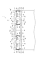
- the second seal groove 37 is formed so that the second seal member 62 faces the counter bore 26 of the inner ring 20, and the spacer 70
- the axial positional relationship between the second seal groove 37 and the second O-ring groove 39 may be reversed.
- the sealing performance is good even when the angular ball bearings 10A and 10B are handled alone. It is possible to maintain and prevent entry of foreign matter from the outside.
- the number of O-ring grooves provided on the outer peripheral portion of the outer ring 30 is not limited to two as in the above-described embodiment, and it is sufficient that at least one is provided, and three considering the strength of the outer ring 30. It does not matter as above.
- Rotating body support apparatus 10 Combination bearing 10A, 10B Angular contact ball bearing 20
- Inner ring 21 Axial outer surface (Axial one side surface) 22
- Inner ring raceway surface 23 Axial inner side surface 24
- Inner ring shoulder portion 26 Counter bore 28 Recess 30
- Outer ring 30a, 30b Extension portion 31
- Axial outer side surface (Axial one side surface) 32
- Outer ring raceway surface 33
Landscapes
- Engineering & Computer Science (AREA)
- General Engineering & Computer Science (AREA)
- Mechanical Engineering (AREA)
- Rolling Contact Bearings (AREA)
- Sealing Of Bearings (AREA)
Description
(1) 外周部に内輪軌道面が形成された内輪と、
内周部に外輪軌道面が形成された外輪と、
前記内輪軌道面及び前記外輪軌道面との間に接触角を持って組み込まれた複数の玉と、
を有するアンギュラ玉軸受であって、
前記外輪の軸方向幅が、ISOにおける幅系列で0より大きく、
前記内輪の外周部は、前記内輪軌道面に対して軸方向一方側に形成された内輪肩部と、軸方向他方側に形成されたカウンタボアと、を有し、
前記外輪の内周部は、前記外輪軌道面を挟んだ軸方向両側に形成された一対の外輪肩部と、前記内輪肩部と対向する前記外輪肩部に対して軸方向一方側にシール部材を固定するために形成されたシール溝と、前記カウンタボアと対向する前記外輪肩部に対して軸方向他方側に他のシール部材を固定するために形成された他のシール溝と、を有し、
内部がグリースによって潤滑される
ことを特徴とするアンギュラ玉軸受。
(2) 前記外輪の軸方向幅は、ISOにおける幅系列で1より大きい
ことを特徴とする(1)に記載のアンギュラ玉軸受。
(3) 前記外輪の外周部には、Oリングを固定するためのOリング溝が少なくとも1つ設けられることを特徴とする(1)又は(2)に記載のアンギュラ玉軸受。
(4) 前記外輪の外周部には、前記Oリング溝が2つ以上設けられる
ことを特徴とする(3)に記載のアンギュラ玉軸受。
(5) 前記外輪には、軸方向一方側から順に、前記シール溝、前記Oリング溝、前記外輪軌道面がオフセットして設けられる
ことを特徴とする(3)又は(4)に記載のアンギュラ玉軸受。
(6) 前記外輪には、軸方向一方側から順に、前記Oリング溝、前記シール溝、前記外輪軌道面がオフセットして設けられる
ことを特徴とする(3)又は(4)に記載のアンギュラ玉軸受。
(7) 前記シール部材及び前記他のシール部材は、前記内輪の外周部に対向する
ことを特徴とする(1)~(6)の何れか1つに記載のアンギュラ玉軸受。
(8) 前記内輪の軸方向幅は、前記外輪の軸方向幅よりも小さい
ことを特徴とする(1)~(7)の何れか1つに記載のアンギュラ玉軸受。
(9) 前記内輪の軸方向一方側端面と、前記外輪の軸方向一方側端面と、は略同一位置である
ことを特徴とする(1)~(8)の何れか1つに記載のアンギュラ玉軸受。
(10) (1)~(9)の何れか1つに記載の前記アンギュラ玉軸受を一対組合せてなる
ことを特徴とする組合せ軸受。
(11) 一対の前記アンギュラ玉軸受の内輪の軸方向における間には、間座が配置される
ことを特徴とする(10)に記載の組合せ軸受。
第1実施形態において、図示しない工作機械等の産業機械の回転軸をハウジングに回転自在に支持する回転体支持装置1は、図1に示すように、一対の単列アンギュラ玉軸受10A及び10Bを接触角が略ハの字を表すように二列背面組合せて構成された組合せ軸受10からなる。
次に、第2実施形態に係る組合せ軸受について説明する。なお、本実施形態の組合せ軸受は、第1実施形態の組合せ軸受と基本的構成を同一とするので、同一又は相当部分には同一符号を付して、その説明を省略又は簡略化し、相違部分を中心に説明する。
図3に示すように、第2実施形態に係る組合せ軸受10において、内輪20の軸方向内側面23が外輪30の軸方向内側面33よりも軸方向外側に位置するよう、内輪20の軸方向幅を短く設定してもよい。このとき、単列アンギュラ玉軸受10A及び10Bの内輪20、20の軸方向における間には、間座70が配置される。このように構成した場合、カウンタボア26、26を短くすることができ、強度維持に必要な肉厚を確保することが可能である。
さらに、図4に示すように、第1変形例に係る組合せ軸受10において、第二シール部材62が内輪20のカウンタボア26に対向するように第二シール溝37を形成し、間座70と軸方向にオーバーラップするように第二Oリング溝39を形成することによって、第二シール溝37と第二Oリング溝39の軸方向位置関係を逆転させても構わない。この場合、外輪30に固定された第一シール部材61及び第二シール部材62は、内輪20の外周部に対向するので、アンギュラ玉軸受10A、10Bを単体で取り扱う場合であっても密封性が維持でき、外部からの異物浸入を防止することが可能である。
10 組合せ軸受
10A、10B アンギュラ玉軸受
20 内輪
21 軸方向外側面(軸方向一方側側面)
22 内輪軌道面
23 軸方向内側面
24 内輪肩部
26 カウンタボア
28 凹部
30 外輪
30a、30b 延在部
31 軸方向外側面(軸方向一方側側面)
32 外輪軌道面
33 軸方向内側面
34、35 外輪肩部
36、37 シール溝
38、39 Oリング溝
40 玉
50 保持器
61、62 シール部材
61a、62a 芯金
61b、62b 弾性体
61c、62c リップ
70 間座
Claims (11)
- 外周部に内輪軌道面が形成された内輪と、
内周部に外輪軌道面が形成された外輪と、
前記内輪軌道面及び前記外輪軌道面との間に接触角を持って組み込まれた複数の玉と、
を有するアンギュラ玉軸受であって、
前記外輪の軸方向幅が、ISOにおける幅系列で0より大きく、
前記内輪の外周部は、前記内輪軌道面に対して軸方向一方側に形成された内輪肩部と、軸方向他方側に形成されたカウンタボアと、を有し、
前記外輪の内周部は、前記外輪軌道面を挟んだ軸方向両側に形成された一対の外輪肩部と、前記内輪肩部と対向する前記外輪肩部に対して軸方向一方側にシール部材を固定するために形成されたシール溝と、前記カウンタボアと対向する前記外輪肩部に対して軸方向他方側に他のシール部材を固定するために形成された他のシール溝と、を有し、
内部がグリースによって潤滑される
ことを特徴とするアンギュラ玉軸受。 - 前記外輪の軸方向幅は、ISOにおける幅系列で1より大きい
ことを特徴とする請求項1に記載のアンギュラ玉軸受。 - 前記外輪の外周部には、Oリングを固定するためのOリング溝が少なくとも1つ設けられる
ことを特徴とする請求項1又は2に記載のアンギュラ玉軸受。 - 前記外輪の外周部には、前記Oリング溝が2つ以上設けられる
ことを特徴とする請求項3に記載のアンギュラ玉軸受。 - 前記外輪には、軸方向一方側から順に、前記シール溝、前記Oリング溝、前記外輪軌道面がオフセットして設けられる
ことを特徴とする請求項3又は4に記載のアンギュラ玉軸受。 - 前記外輪には、軸方向一方側から順に、前記Oリング溝、前記シール溝、前記外輪軌道面がオフセットして設けられる
ことを特徴とする請求項3又は4に記載のアンギュラ玉軸受。 - 前記シール部材及び前記他のシール部材は、前記内輪の外周部に対向する
ことを特徴とする請求項1~6の何れか1項に記載のアンギュラ玉軸受。 - 前記内輪の軸方向幅は、前記外輪の軸方向幅よりも小さい
ことを特徴とする請求項1~7の何れか1項に記載のアンギュラ玉軸受。 - 前記内輪の軸方向一方側端面と、前記外輪の軸方向一方側端面と、は略同一位置であることを特徴とする請求項1~8の何れか1項に記載のアンギュラ玉軸受。
- 請求項1~9の何れか1項に記載の前記アンギュラ玉軸受を一対組合せてなる
ことを特徴とする組合せ軸受。 - 一対の前記アンギュラ玉軸受の内輪の軸方向における間には、間座が配置される
ことを特徴とする請求項10に記載の組合せ軸受。
Priority Applications (2)
| Application Number | Priority Date | Filing Date | Title |
|---|---|---|---|
| CN201390000036.9U CN203743212U (zh) | 2012-07-19 | 2013-03-14 | 角接触球轴承以及组合式轴承 |
| DE201321000161 DE212013000161U1 (de) | 2012-07-19 | 2013-03-14 | Schrägkugellager und Kombinationslager |
Applications Claiming Priority (2)
| Application Number | Priority Date | Filing Date | Title |
|---|---|---|---|
| JP2012-160611 | 2012-07-19 | ||
| JP2012160611A JP2014020481A (ja) | 2012-07-19 | 2012-07-19 | アンギュラ玉軸受 |
Publications (1)
| Publication Number | Publication Date |
|---|---|
| WO2014013754A1 true WO2014013754A1 (ja) | 2014-01-23 |
Family
ID=49948591
Family Applications (1)
| Application Number | Title | Priority Date | Filing Date |
|---|---|---|---|
| PCT/JP2013/057263 Ceased WO2014013754A1 (ja) | 2012-07-19 | 2013-03-14 | アンギュラ玉軸受及び組合せ軸受 |
Country Status (4)
| Country | Link |
|---|---|
| JP (1) | JP2014020481A (ja) |
| CN (1) | CN203743212U (ja) |
| DE (1) | DE212013000161U1 (ja) |
| WO (1) | WO2014013754A1 (ja) |
Cited By (4)
| Publication number | Priority date | Publication date | Assignee | Title |
|---|---|---|---|---|
| CN107429746A (zh) * | 2015-03-12 | 2017-12-01 | 斯凯孚公司 | 在滚动轴承中保持润滑剂的装置、滚动轴承组件和滚动轴承组件的组装方法 |
| CN108708909A (zh) * | 2018-07-24 | 2018-10-26 | 安徽利达汽车轴承制造有限公司 | 一种角接触球轴承密封圈 |
| TWI709695B (zh) * | 2016-06-03 | 2020-11-11 | 日商恩天股份有限公司 | 多列組合斜角滾珠軸承裝置 |
| CN112483553A (zh) * | 2019-09-11 | 2021-03-12 | 斯凯孚公司 | 滚动轴承装置和滚动轴承 |
Families Citing this family (6)
| Publication number | Priority date | Publication date | Assignee | Title |
|---|---|---|---|---|
| CN104006082A (zh) * | 2014-05-08 | 2014-08-27 | 洛阳德润精密机床轴承有限公司 | 外圈可重复注脂的角接触球轴承 |
| WO2017168610A1 (ja) * | 2016-03-30 | 2017-10-05 | 株式会社ハーモニック・ドライブ・システムズ | 組合せ円筒コロ軸受 |
| KR102355566B1 (ko) * | 2017-09-01 | 2022-01-25 | 닛본 세이고 가부시끼가이샤 | 앵귤러 볼 베어링, 베어링 장치 및 주축 장치 |
| JP7003683B2 (ja) * | 2017-09-01 | 2022-01-20 | 日本精工株式会社 | アンギュラ玉軸受、軸受装置、及び主軸装置 |
| WO2023095740A1 (ja) | 2021-11-25 | 2023-06-01 | Ntn株式会社 | シール付軸受 |
| JP7724145B2 (ja) * | 2021-12-08 | 2025-08-15 | Ntn株式会社 | シール付玉軸受 |
Citations (8)
| Publication number | Priority date | Publication date | Assignee | Title |
|---|---|---|---|---|
| JPH032921U (ja) * | 1989-06-01 | 1991-01-11 | ||
| JP2000230564A (ja) * | 1999-02-10 | 2000-08-22 | Nsk Ltd | 回転軸支持構造 |
| JP2006161876A (ja) * | 2004-12-03 | 2006-06-22 | Nsk Ltd | 転がり軸受 |
| JP2007239801A (ja) * | 2006-03-06 | 2007-09-20 | Nsk Ltd | シール付きアンギュラ玉軸受 |
| JP2008240806A (ja) * | 2007-03-26 | 2008-10-09 | Jtekt Corp | 玉軸受 |
| JP2010001924A (ja) * | 2008-06-18 | 2010-01-07 | Nsk Ltd | 組合せ軸受 |
| JP2010164122A (ja) * | 2009-01-15 | 2010-07-29 | Ntn Corp | アンギュラ玉軸受 |
| JP2012077851A (ja) * | 2010-10-01 | 2012-04-19 | Ntn Corp | 転がり軸受装置 |
Family Cites Families (8)
| Publication number | Priority date | Publication date | Assignee | Title |
|---|---|---|---|---|
| JPH04177061A (ja) | 1990-11-09 | 1992-06-24 | Hitachi Ltd | 空気調和機 |
| JPH11108068A (ja) | 1997-09-30 | 1999-04-20 | Ntn Corp | アンギュラ玉軸受 |
| JP2002122149A (ja) | 2000-10-12 | 2002-04-26 | Ntn Corp | アンギュラ玉軸受およびこれを用いた工作機械 |
| JP2005042894A (ja) * | 2003-07-25 | 2005-02-17 | Nsk Ltd | 複列転がり軸受装置 |
| JP2005076660A (ja) | 2003-08-29 | 2005-03-24 | Nsk Ltd | 転がり軸受装置 |
| JP2006161943A (ja) | 2004-12-07 | 2006-06-22 | Ntn Corp | アンギュラ玉軸受 |
| JP5844596B2 (ja) * | 2010-10-21 | 2016-01-20 | Ntn株式会社 | 転がり軸受装置 |
| JP5547667B2 (ja) | 2011-02-01 | 2014-07-16 | ルネサスエレクトロニクス株式会社 | 半導体装置 |
-
2012
- 2012-07-19 JP JP2012160611A patent/JP2014020481A/ja active Pending
-
2013
- 2013-03-14 DE DE201321000161 patent/DE212013000161U1/de not_active Expired - Lifetime
- 2013-03-14 WO PCT/JP2013/057263 patent/WO2014013754A1/ja not_active Ceased
- 2013-03-14 CN CN201390000036.9U patent/CN203743212U/zh not_active Expired - Lifetime
Patent Citations (8)
| Publication number | Priority date | Publication date | Assignee | Title |
|---|---|---|---|---|
| JPH032921U (ja) * | 1989-06-01 | 1991-01-11 | ||
| JP2000230564A (ja) * | 1999-02-10 | 2000-08-22 | Nsk Ltd | 回転軸支持構造 |
| JP2006161876A (ja) * | 2004-12-03 | 2006-06-22 | Nsk Ltd | 転がり軸受 |
| JP2007239801A (ja) * | 2006-03-06 | 2007-09-20 | Nsk Ltd | シール付きアンギュラ玉軸受 |
| JP2008240806A (ja) * | 2007-03-26 | 2008-10-09 | Jtekt Corp | 玉軸受 |
| JP2010001924A (ja) * | 2008-06-18 | 2010-01-07 | Nsk Ltd | 組合せ軸受 |
| JP2010164122A (ja) * | 2009-01-15 | 2010-07-29 | Ntn Corp | アンギュラ玉軸受 |
| JP2012077851A (ja) * | 2010-10-01 | 2012-04-19 | Ntn Corp | 転がり軸受装置 |
Cited By (6)
| Publication number | Priority date | Publication date | Assignee | Title |
|---|---|---|---|---|
| CN107429746A (zh) * | 2015-03-12 | 2017-12-01 | 斯凯孚公司 | 在滚动轴承中保持润滑剂的装置、滚动轴承组件和滚动轴承组件的组装方法 |
| CN107429746B (zh) * | 2015-03-12 | 2020-07-03 | 斯凯孚公司 | 在滚动轴承中保持润滑剂的装置、滚动轴承组件和滚动轴承组件的组装方法 |
| TWI709695B (zh) * | 2016-06-03 | 2020-11-11 | 日商恩天股份有限公司 | 多列組合斜角滾珠軸承裝置 |
| CN108708909A (zh) * | 2018-07-24 | 2018-10-26 | 安徽利达汽车轴承制造有限公司 | 一种角接触球轴承密封圈 |
| CN108708909B (zh) * | 2018-07-24 | 2023-12-15 | 安徽利达汽车轴承制造有限公司 | 一种角接触球轴承密封圈 |
| CN112483553A (zh) * | 2019-09-11 | 2021-03-12 | 斯凯孚公司 | 滚动轴承装置和滚动轴承 |
Also Published As
| Publication number | Publication date |
|---|---|
| JP2014020481A (ja) | 2014-02-03 |
| DE212013000161U1 (de) | 2015-03-02 |
| CN203743212U (zh) | 2014-07-30 |
Similar Documents
| Publication | Publication Date | Title |
|---|---|---|
| WO2014013754A1 (ja) | アンギュラ玉軸受及び組合せ軸受 | |
| JP5870563B2 (ja) | 転がり軸受用保持器、及び転がり軸受 | |
| JP6565366B2 (ja) | アンギュラ玉軸受 | |
| WO2015012337A1 (ja) | 密封装置付き転がり軸受 | |
| KR102593405B1 (ko) | 캠장치 | |
| EP2497914A1 (en) | Camshaft apparatus | |
| CN101454585B (zh) | 带有减小的保持架兜孔气隙的滚动轴承 | |
| JP5417481B2 (ja) | 歯車伝動装置 | |
| US20160025134A1 (en) | Cage for angular ball bearing | |
| JP6529209B2 (ja) | アンギュラ玉軸受 | |
| CN106499734A (zh) | 用于滚动轴承单元的密封装置 | |
| JP6517041B2 (ja) | 減速装置 | |
| CN103352919A (zh) | 一种实体保持架及加强型实体圆锥滚子轴承 | |
| JP2017096343A (ja) | 撓み噛合い式歯車装置 | |
| CN205991096U (zh) | 角接触球轴承用保持架、角接触球轴承及轴承装置 | |
| JP2015021567A (ja) | 複列軸受 | |
| JP2020070856A (ja) | 軸受および減速機 | |
| JP7306136B2 (ja) | 深溝玉軸受 | |
| US20160178002A1 (en) | Double-row spherical roller bearing | |
| JP7186061B2 (ja) | 玉軸受 | |
| JP2007292093A (ja) | 深溝玉軸受 | |
| WO2017043425A1 (ja) | 転がり軸受 | |
| CN205895919U (zh) | 角接触球轴承用保持架、角接触球轴承及轴承装置 | |
| JP5776298B2 (ja) | 分割型転がり軸受および分割型転がり軸受装置 | |
| JP2011231863A (ja) | 複列軸受用保持器および複列転がり軸受 |
Legal Events
| Date | Code | Title | Description |
|---|---|---|---|
| WWE | Wipo information: entry into national phase |
Ref document number: 201390000036.9 Country of ref document: CN |
|
| 121 | Ep: the epo has been informed by wipo that ep was designated in this application |
Ref document number: 13820512 Country of ref document: EP Kind code of ref document: A1 |
|
| WWE | Wipo information: entry into national phase |
Ref document number: 2120130001614 Country of ref document: DE Ref document number: 212013000161 Country of ref document: DE |
|
| 122 | Ep: pct application non-entry in european phase |
Ref document number: 13820512 Country of ref document: EP Kind code of ref document: A1 |