WO2014002889A1 - フレキシブル集約配線コネクタ - Google Patents
フレキシブル集約配線コネクタ Download PDFInfo
- Publication number
- WO2014002889A1 WO2014002889A1 PCT/JP2013/067073 JP2013067073W WO2014002889A1 WO 2014002889 A1 WO2014002889 A1 WO 2014002889A1 JP 2013067073 W JP2013067073 W JP 2013067073W WO 2014002889 A1 WO2014002889 A1 WO 2014002889A1
- Authority
- WO
- WIPO (PCT)
- Prior art keywords
- flexible
- connector
- flat cable
- locking
- slider
- Prior art date
- Legal status (The legal status is an assumption and is not a legal conclusion. Google has not performed a legal analysis and makes no representation as to the accuracy of the status listed.)
- Ceased
Links
Images







Classifications
-
- H—ELECTRICITY
- H01—ELECTRIC ELEMENTS
- H01R—ELECTRICALLY-CONDUCTIVE CONNECTIONS; STRUCTURAL ASSOCIATIONS OF A PLURALITY OF MUTUALLY-INSULATED ELECTRICAL CONNECTING ELEMENTS; COUPLING DEVICES; CURRENT COLLECTORS
- H01R12/00—Structural associations of a plurality of mutually-insulated electrical connecting elements, specially adapted for printed circuits, e.g. printed circuit boards [PCB], flat or ribbon cables, or like generally planar structures, e.g. terminal strips, terminal blocks; Coupling devices specially adapted for printed circuits, flat or ribbon cables, or like generally planar structures; Terminals specially adapted for contact with, or insertion into, printed circuits, flat or ribbon cables, or like generally planar structures
- H01R12/70—Coupling devices
- H01R12/77—Coupling devices for flexible printed circuits, flat or ribbon cables or like structures
- H01R12/771—Details
- H01R12/774—Retainers
-
- H—ELECTRICITY
- H01—ELECTRIC ELEMENTS
- H01R—ELECTRICALLY-CONDUCTIVE CONNECTIONS; STRUCTURAL ASSOCIATIONS OF A PLURALITY OF MUTUALLY-INSULATED ELECTRICAL CONNECTING ELEMENTS; COUPLING DEVICES; CURRENT COLLECTORS
- H01R12/00—Structural associations of a plurality of mutually-insulated electrical connecting elements, specially adapted for printed circuits, e.g. printed circuit boards [PCB], flat or ribbon cables, or like generally planar structures, e.g. terminal strips, terminal blocks; Coupling devices specially adapted for printed circuits, flat or ribbon cables, or like generally planar structures; Terminals specially adapted for contact with, or insertion into, printed circuits, flat or ribbon cables, or like generally planar structures
- H01R12/70—Coupling devices
- H01R12/77—Coupling devices for flexible printed circuits, flat or ribbon cables or like structures
- H01R12/771—Details
- H01R12/772—Strain relieving means
-
- H—ELECTRICITY
- H01—ELECTRIC ELEMENTS
- H01R—ELECTRICALLY-CONDUCTIVE CONNECTIONS; STRUCTURAL ASSOCIATIONS OF A PLURALITY OF MUTUALLY-INSULATED ELECTRICAL CONNECTING ELEMENTS; COUPLING DEVICES; CURRENT COLLECTORS
- H01R12/00—Structural associations of a plurality of mutually-insulated electrical connecting elements, specially adapted for printed circuits, e.g. printed circuit boards [PCB], flat or ribbon cables, or like generally planar structures, e.g. terminal strips, terminal blocks; Coupling devices specially adapted for printed circuits, flat or ribbon cables, or like generally planar structures; Terminals specially adapted for contact with, or insertion into, printed circuits, flat or ribbon cables, or like generally planar structures
- H01R12/70—Coupling devices
- H01R12/77—Coupling devices for flexible printed circuits, flat or ribbon cables or like structures
- H01R12/79—Coupling devices for flexible printed circuits, flat or ribbon cables or like structures connecting to rigid printed circuits or like structures
Definitions
- the present invention relates to a flexible concentrated wiring connector.
- flexible flat cable Flexible Flat Cable
- flexible wiring board Flexible printed
- Flexible integrated wiring such as circuits
- Such a terminal portion of the flexible aggregated wiring is normally connected to other electric circuits via a detachable flexible aggregated wiring connector (see Patent Documents 1 to 3).
- the flexible integrated wiring connector in Patent Document 1 will be described with reference to FIGS.
- the flexible aggregated wiring connector 1 in Patent Document 1 includes a slider 5 on which a mounting surface 4 on which a terminal portion 3 of the flexible aggregated wiring 2 is installed and a slider 5. And a cover 6 that presses the terminal portion 3 of the flexible aggregated wiring 2 against the mounting surface 4 of the slider 5.
- the slider 5 has positioning bosses 7a formed on both ends of the mounting surface 4 in the width direction (that is, the X direction in FIG. 7), and protrusions 7b are formed on both side surfaces connected to the both ends. .
- the cover 6 is extended along the side surface of the slider 5 from the both ends of the longitudinal member 6a extending in the arrangement direction of the terminal portions 3 in the flexible aggregated wiring 2, and the longitudinal member 6a, and the projection 7b on the side surface. And an engaging member 6b in which an opening that can be locked is formed. Boss holes 2a, 2a are formed in the flexible aggregated wiring 2 at positions corresponding to the positioning bosses 7a, 7a.
- the positioning bosses 7a, 7a of the slider 5 are inserted into the boss holes 2a, 2a of the flexible aggregated wiring 2, and the terminal 3 Is placed on the mounting surface 4 of the slider 5. Then, the long member 6 a of the cover 6 covers the flexible aggregated wiring 2, the engaging member 6 b of the cover 6 is engaged with the protrusion 7 b on the side surface of the slider 5, and the flexible aggregated wiring 2 and the slider 5 are brought into close contact with each other.
- Japanese Unexamined Patent Publication No. 2011-44381 Japanese Unexamined Patent Publication No. 2011-40226 Japanese Unexamined Patent Publication No. 2010-3443
- the flexible aggregated wiring 2 is extended depending on the wiring layout in a state where it is assembled in various electronic devices and electric devices, and the handling in the state where it is assembled in the flexible aggregated wiring connector 1 (that is, how to hold it).
- the part may be bent and used.
- the terminal part 3 of the flexible aggregated wiring 2 may be bent and deformed.
- FIG. 8A and FIG. 8B are diagrams showing an example of the deflection deformation of the terminal portion 3 when the extending portion 8 connected to the terminal portion 3 of the flexible aggregated wiring 2 is bent and used.
- FIG. 8A is a side view of the flexible aggregated wiring connector 1
- FIG. 8B is a diagram of the flexible aggregated wiring connector 1 viewed from the terminal portion 3 side.
- the broken line in FIG. 8A shows a state where the extended portion 8 of the flexible aggregated wiring 2 is not bent.
- illustration of the bent extended portion 8 is omitted for the explanation of the bending deformation of the terminal portion 3 of the flexible aggregated wiring 2.
- the longitudinal member 6a is bent and deformed in a concave shape. That is, both ends of the longitudinal member 6a of the cover 6 are locked to the protrusions 7b on the side surface of the slider 5 by the engaging member 6b, while the central portion of the longitudinal member 6a is not locked to the slider 5. For this reason, the center part of the longitudinal member 6a is bent and deformed due to insufficient reaction force due to the thin thickness. As a result, there is a possibility that the electrical reliability may be impaired due to a decrease in adhesion between the flexible aggregated wiring 2 and the flexible aggregated wiring connector 1 or a poor fitting with the connector of the connection partner.
- a method of avoiding contact between the cover 6 and the PCB 9 by increasing the contact position of the flexible aggregate wiring connector 1 in the PCB connector 10 is also conceivable.
- the PCB connector 10 is increased in size. Since the PCB connector 10 has a strong need for downsizing, this method cannot be adopted.
- the present invention has been made in view of the above-described circumstances, and an object of the present invention is to provide a flexible concentrated wiring connector capable of suppressing the flexible concentrated wiring from being bent in a direction opposite to the mounting surface.
- a flexible concentrated wiring connector is characterized by the following (1) to (5).
- the flexible aggregated wiring connector of (1) above, The width between the pair of locking hooks is slightly smaller than the width between the pair of locking holes.
- Projections are formed at both ends in the width direction of the placement surface.
- the flexible integrated wiring connector according to any one of (1) to (3) above On both end sides in the width direction of the mounting surface, tapered portions are formed so as to be inclined so that the protruding amount increases from the center side toward both end sides.
- the locking hook is A digging portion formed on the mounting surface, and A flexible arm portion extending from the bottom of the digging portion and formed to protrude from the mounting surface; And a return portion protruding from the protruding end of the arm portion and locking the locking hole.
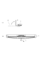
- FIG. 1 (a) to 1 (d) are diagrams showing the flexible concentrated wiring connector in the first embodiment
- FIG. 1 (a) is a side view seen from the terminal portion side
- FIG. 1 (b) is a plan view
- FIG. 1 (c) is a cross-sectional view taken along the line AA in FIG. 1 (b)
- FIG. 1 (d) is a side view as seen from the side.
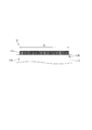
- FIG. 2 is a partially enlarged view showing the flexible concentrated wiring connector in the first embodiment, and is an enlarged view of a portion B in FIG.
- FIG. 3 is a diagram illustrating a terminal portion of the flexible aggregated wiring according to the first embodiment.
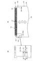
- FIG. 4 (a) and 4 (b) are views showing a state in which the flexible aggregated wiring is assembled to the flexible aggregated wiring connector
- FIG. 4 (a) is a plan view
- FIG. 4 (b) is a diagram of FIG. 4 (a).
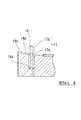
- FIG. FIG. 5 is a cross-sectional view illustrating a state in which the flexible aggregated wiring is assembled to the flexible aggregated wiring connector, and is an enlarged view of a portion D in FIG.
- FIG. 6 is a perspective view showing a conventional flexible collective wiring connector and a PCB connector.
- FIG. 7 is an exploded view showing a conventional flexible collective wiring connector.
- 8 (a) and 8 (b) are diagrams showing the bending deformation of the terminal portion when the extended portion of the flexible aggregated wiring is bent and used, and FIG.
- FIG. 8 (a) is a flexible aggregated wiring connector.
- FIG. 8B is a view of the flexible aggregated wiring connector as viewed from the terminal side.
- FIG. 9 is a diagram illustrating a state in which the flexible aggregate wiring connector and the PCB connector are connected.
- FIG. 10 is a diagram showing the assembly structure according to the second embodiment from the flat cable side.
- FIG. 11 is a diagram showing the assembly structure according to the second embodiment from the slider side.
- FIG. 12 is a diagram showing a state in which the flat cable and the slider are assembled to each other.
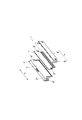
- FIG. 13 is a perspective view for explaining the assembly of the flat cable, the slider, and the connector assembled to each other.
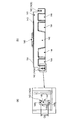
- 14 (a) and 14 (b) are diagrams showing the configuration of the flat cable.
- FIG. 14 (a) is a plan view from above, and FIG. 14 (b) is a part of FIG. 14 (a).
- FIG. 15 (a) and 15 (b) are diagrams showing the configuration of the slider, FIG. 15 (a) is a plan view from above, and FIG. 15 (b) is an enlarged view of part of FIG. 15 (a). It is a figure shown.
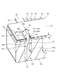
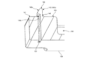
- FIG. 16 is a diagram showing a vertical cross section at the portion indicated by arrow A3 in FIG. 12 from the direction of the arrow, and is a perspective view from above of a state where the flat cable and the slider are assembled.
- FIG. 17 is a view showing a vertical cross section of the arrow A3 portion of FIG.
- FIG. 18 is a view showing a longitudinal section corresponding to the arrow A3 portion of FIG. 12 from the arrow direction, and is a perspective view from the upper side in a state where the flat cable and the slider are assembled.
- FIG. 19 is a view showing a longitudinal section corresponding to the arrow A3 portion of FIG. 12 from the arrow direction, and is a perspective view from the lower side of the slider alone.
- FIG. 1 (a) to 1 (d) are diagrams showing the flexible concentrated wiring connector 11 in the present embodiment.
- 1A is a side view seen from the terminal side
- FIG. 1B is a plan view
- FIG. 1C is a cross-sectional view taken along line AA in FIG. 1B
- FIG. The side view seen from is shown.
- the flexible aggregated wiring connector 11 has a terminal portion 13 of the flexible aggregated wiring 12 along the width direction of one surface (the lower surface in FIG. 1A) (that is, the horizontal direction in FIG. 1A).
- a placement surface 14 to be placed is formed.
- a pair of locking holes 12a and 12b that are respectively formed at both ends in the width direction of the terminal portion 13 of the flexible aggregated wiring 12 are respectively inserted into the both ends in the width direction of the mounting surface 14. Locking hooks 17 and 17 are provided upright.
- the locking hooks 17 and 17 are formed by a base portion 17 a erected from the placement surface 14 and a projection portion 17 b protruding from the base portion 17 a toward the center side in the terminal portion arrangement direction.
- the locking hooks 17, 17 are formed so as to extend from the digging portion 18 formed on the mounting surface 14 and the bottom portion 18 a of the digging portion 18 and protrude beyond the mounting surface 14.
- it has a flexible base portion 17a (arm portion), and a protruding portion 17b (return portion) that protrudes from the protruding end of the base portion 17a and locks the locking holes 12a and 12b.
- the width d between the locking hooks 17 and 17 shown in FIG. 1B is designed to be slightly smaller than the width D between the locking holes 12a and 12b of the flexible aggregated wiring 12. As shown in FIG. 1B, the locking hooks 17 and 17 are provided so as to be shifted from each other with respect to the insertion direction of the flexible aggregated wiring 12. This is to prevent the conductor exposed surface 12c of the flexible aggregated wiring 12 from being placed toward the placement surface 14 side.
- the mounting surface 14 of the flexible collective wiring connector 11 has a flat central portion in the width direction.
- tapered portions 14a are formed so as to be inclined toward the flexible aggregate wiring side from the center side toward both end sides. That is, the taper portion 14a is inclined so that the protruding amount increases as it goes from the center side to both end sides.
- protrusions 14 b that protrude toward the flexible aggregated wiring 12 are formed. That is, the protrusions 14b are disposed on both sides of the mounting surface 14 further than the taper portions 14a.
- the flexible aggregated wiring 12 As the flexible aggregated wiring 12 (see FIG. 3) in the first embodiment, a plurality of arranged foil-shaped conductors are sandwiched between insulating films, and an insulating film on one surface is cut to connect to another electric circuit.
- a flexible flat cable (FFC) in which the terminal portion of each conductor is exposed can be used.
- a flexible wiring board or the like in which a terminal portion made of a plurality of foil-like conductors is formed on the edge of the board in order to connect an electric circuit formed on the flexible board to an external electric circuit, etc. (FPC) or the like can also be used.
- the flexible aggregated wiring 12 has an extension portion connected to the terminal portion 13 in an appropriate length depending on the intended use, but is omitted for the sake of simplicity of illustration.
- the flexible aggregated wiring 12 has locking holes 12 a and 12 b into which the locking hooks 17 and 17 of the flexible aggregated wiring connector 11 are inserted on both side edges in the width direction of the terminal portion 13. It is installed.
- the width D between the locking holes 12a and 12b is designed to be slightly wider than the width d between the locking hooks 17 and 17.
- the locking holes 12a and 12b are provided so as to be shifted from each other with respect to the insertion direction, like the locking hooks 17 and 17.
- the locking holes 12a, 12b are aligned with the locking hooks 17, 17 of the flexible concentrated wiring connector 11, and the locking holes 12a, 12b are inserted into the locking hooks 17, 17.
- the flexible aggregated wiring 12 is locked to the protrusion 17 b and assembled to the flexible aggregated wiring connector 11.
- FIGS. 4A to 5 are views showing a state in which the flexible aggregated wiring 12 is assembled to the flexible aggregated wiring connector 11.
- 4A is a plan view
- FIG. 4B is a sectional view taken along the line CC of FIG. 4A
- FIG. 5 is an enlarged view of one end side.
- the width D between the locking holes 12 a and 12 b of the flexible aggregated wiring 12 is larger than the width d between the locking hooks 17 and 17 of the flexible aggregated wiring connector 11. Since it is designed, the flexible aggregate wiring 12 bends. At this time, both side edges of the flexible aggregated wiring 12 are pushed up from the protrusions 14b at both ends of the flexible aggregated wiring connector 11, and the bending direction of the flexible aggregated wiring is forced to the mounting surface 14 side. Further, since the flexible aggregated wiring 12 follows the shape of the tapered portion 14 a, the flexible aggregated wiring 12 is pressed against the mounting surface 14 of the flexible aggregated wiring connector 11.
- the flexible aggregated wiring 12 assembled to the flexible aggregated wiring connector 11 is inserted into, for example, a PCB connector (that is, a connector to be connected) attached to a printed wiring board (PCB) (not shown).
- the terminal portion 13 of the flexible aggregated wiring 12 is connected to a connection terminal inserted into the mouth and provided inside the PCB connector.
- the flexible concentrated wiring 12 which has flexibility, since it is being fixed by the flexible consolidated wiring connector 11, it can insert and connect the flexible concentrated wiring 12 stably against the insertion resistance by the side of a PCB connector. . Further, in a state where the flexible aggregated wiring 12 is inserted and connected to the PCB connector, the locking member 15 formed on the flexible aggregated wiring connector 11 is engaged with the protrusion of the PCB connector to hold the inserted state.
- the terminal portion 13 of the flexible aggregated wiring 12 is placed on the mounting surface due to the extended portion of the flexible aggregated wiring 12 being bent and used. Even if an elastic force that tends to rise from 14 is applied, the terminal portion 13 of the flexible aggregated wiring 12 can always be brought into close contact with the mounting surface 14 of the flexible aggregated wiring connector 11. That is, since the width d between the locking hooks 17 and 17 is narrower than the width D between the locking holes 12a and 12b, the terminal portion 13 bends. At this time, the direction in which the terminal portion 13 bends is forced to the placement surface 14 side by the protrusions 14 b at both ends of the placement surface 14.
- the flexible aggregated wiring 12 is deformed by the tapered portion 14a so as to follow the shape of the tapered portion 14a. As a result, it is possible to suppress the terminal portion 13 of the flexible aggregated wiring 12 from being bent and deformed in the direction opposite to the placement surface 14 and to secure stable electrical reliability.
- the terminal portion 13 of the flexible aggregated wiring 12 is forcibly bent and deformed toward the placement surface 14 side.
- the adhesion between the terminal portion 13 and the placement surface 14 of the flexible aggregated wiring connector 11 can be enhanced. Therefore, stable electrical reliability can be ensured.
- the flexible integrated wiring connector 11 in the first embodiment does not require a cover as compared with the conventional case, the number of parts can be reduced and the cost can be reduced. Further, since it is not necessary to increase the thickness of the cover to improve the reaction force, poor fitting between the flexible concentrated wiring connector 11 and the PCB connector caused by contact between the cover and the PCB, disconnection of the PCB pattern, terminal deformation, Generation
- the flexible aggregated wiring connector 11 according to the first embodiment is used when the terminal portion 13 of the flexible aggregated wiring 12 is inserted and connected to the connector of the connection partner.
- the flexible collective wiring connector 11 includes a mounting surface 14 on which the terminal portion 13 is mounted, and a pair of locking hooks 17 and 17 formed on both end sides in the width direction of the mounting surface 14. ing.
- the pair of locking hooks 17, 17 are engaged with a pair of locking holes 12 a, 12 b drilled on both end sides in the width direction of the terminal portion 13.
- the width between the pair of locking hooks 17 and 17 is slightly smaller than the width between the pair of locking holes 12a and 12b.
- protrusions 14b are formed at both ends of the mounting surface 14 in the width direction.
- the taper portions that incline so that the protruding amount increases toward the both end sides from the center side on each of the both end sides in the width direction of the mounting surface 14. 14a is formed.
- the locking hooks 17, 17 extend from the digging portion 18 formed on the mounting surface 14 and the bottom 18 a of the digging portion 18.
- a flexible base portion 17a (arm portion) formed so as to protrude from the mounting surface 14 and protruding from the protruding end of the base portion 17a.
- a protruding portion 17b return portion
- the inclination angle of the taper portion 14a on the mounting surface 14, the size of the protrusion 14b, and the like can be appropriately selected according to the dimensions of the flexible aggregated wiring connector 11 and the flexible aggregated wiring 12.
- the locking hook 17 is not limited to the shape of the first embodiment, and can be appropriately selected as long as the flexible aggregated wiring 12 can be locked.
- FPC Flexible Printed Circuit
- FFC flexible flat cables
- flat cables in order to connect an electric circuit formed on a flexible substrate to an external electric circuit, a terminal portion made of a plurality of foil-like conductors is formed on the edge of the substrate.
- the FFC is formed with a plurality of foil-shaped conductors arranged between each other with an insulating film and terminal portions for connecting to other electric circuits at both ends.
- the flat cable terminal has low rigidity, and there is a problem that it is deformed by insertion resistance when inserted into the connector or insufficient insertion occurs.
- the connection form which assembles attaches the terminal connector which has rigidity to the terminal part of a flat cable, and inserts in a connector via the assembled terminal connector (refer patent document 3).
- the connector has a terminal for connecting to another electric circuit, and by inserting the terminal connector into the connector, the terminal of the connector and the terminal portion (conductor) of the flat cable come into contact with each other. The terminal and the terminal portion (conductor) are electrically connected.
- a guide member (hereinafter referred to as a slider) having a mounting surface on which a terminal portion of a flat cable is mounted and a terminal portion of the flat cable mounted on the mounting surface are mounted.
- the structure of the terminal connector provided with the cover pressed on a surface is disclosed.
- the slider is an interface member for guiding the flat cable when the flat cable is inserted into the connector and connecting the inserted flat cable to the connector.
- protrusions are formed on the side surfaces of the slider that are continuous with both end surfaces of the mounting surface.
- the cover is provided with a longitudinal member extending in the width direction of the end portion of the flat cable and an opening that can be suspended from both ends of the longitudinal member along the side surface of the slider and can be locked to the projection on the side surface.
- an engaging member When assembling such a terminal connector to the terminal portion of the flat cable, the longitudinal member of the cover is positioned on the terminal portion mounted on the mounting surface of the slider, and the engaging member of the cover is pushed down along the side surface of the slider. Then, the opening of the engaging member is engaged with the protrusion on the side surface of the slider. In this way, the slider and the cover are assembled with the terminal portion sandwiched. And the terminal connector and flat cable which consist of these sliders and covers are assembled. Accordingly, the flat cable is electrically connected to the connector by inserting the terminal connector (slider and cover) assembled to the terminal portion into the connector.
- the terminal connector includes a slider and a cover, and these are assembled to a flat cable. Therefore, in assembling the flat cable and the terminal connector, it is necessary to assemble the flat cable, the slider, and the cover with each other.
- the second embodiment has been made based on this, and the first problem to be solved is to suppress the flat cable from being bent in the opposite direction to the placement surface, as in the first embodiment described above. That is.
- the second problem is to reduce the work load for assembling the flat cable and the terminal connector.
- the assembly structure of the second embodiment includes a flat cable including a conductor and a pair of covering portions that sandwich the conductor, and a slider that inserts the flat cable into a connector for connection (that is, a connector to be connected). It is a structure for assembling.
- a flat cable is a flat flexible cable used for reducing wiring space and improving the degree of freedom of wiring paths in various electronic devices and electric devices.
- a flat circuit cable (FPC: Flexible Printed) Circuit) and flexible flat cable (FFC: Flexible Flat Cable) are assumed.
- the slider guides the flat cable when the flat cable is inserted into a connector for connection to another electric circuit, and serves as an interface for connecting the inserted flat cable to the connector (that is, a terminal connector). .)
- 10 to 15 show the structure of the assembly structure according to the second embodiment.
- 10 is a diagram showing the assembly structure from the flat cable 102 side
- FIG. 11 is a diagram showing the assembly structure from the slider 104 side
- FIG. 12 is a diagram showing a state in which the flat cable 102 and the slider 104 are assembled together.
- 13 is a perspective view for explaining the assembly of the flat cable 102 and the slider 104 and the connector 106 assembled to each other.
- 14 (a) and 14 (b) are diagrams showing the configuration of the flat cable 102
- FIG. 14 (a) is a plan view showing from the upper side
- FIG. 14 (b) is a diagram of FIG. 14 (a). It is a figure which expands and shows a part.
- FIG. 15 (a) and 15 (b) are diagrams showing the configuration of the slider 104, FIG. 15 (a) is a plan view from above, and FIG. 15 (b) is a part of FIG. 15 (a).
- FIG. in the following description the flat cable 102 side is referred to as the upper side and the slider 104 side is referred to as the lower side with respect to the assembly direction of the flat cable 102 and the slider 104 (the arrow Z direction shown in FIG. 10).
- the flat cable 102 includes a plurality of conductors 121 and a pair of covering portions 122 that sandwich the conductors 121.
- the conductor 121 is made of a rectangular or foil-like conductive material, and a plurality of such conductive materials are arranged in parallel to constitute one flat cable 102.
- the covering portion 122 is made of an insulating material (for example, an insulating film made of resin, etc.), and has a configuration in which a plurality of conductors 121 are sandwiched from the upper side and the lower side in a band shape over the length direction.
- the flat cable 102 has the terminal part 123 for connecting with another electric circuit, and this terminal part 123 is one side (the upper side in FIG.
- the entire width of the covering portion 122 is set larger than the entire width of the plurality of conductors 121 in the width direction (that is, the direction of the arrow X shown in FIG. 10).
- a portion composed of only the covering portion 122 hereinafter referred to as a covering end portion 124.
- the terminal portion 123 has a configuration in which the covering end portions 124 at both ends in the width direction X are cut off. Therefore, the flat cable 102 is configured such that the terminal portion 123 is narrower than the other intermediate portion 125.
- the flat cable 102 includes an opening 126 (that is, a locking hole) formed by penetrating the covering portion 122 along the assembly direction Z with the slider 104.
- a pair of openings 126 (126a, 126a, 126) are provided at the covering end portions 124 at both ends in the width direction X and in the vicinity of the terminal portion 123 in the length direction (that is, the arrow Y direction shown in FIG. 10).
- 126b is formed.
- These openings 126 are locked to a locking portion 142 described later.
- the configuration of the opening 126 (that is, the shape, size, arrangement, etc.) can be arbitrarily set as long as the locking portion 142 can be locked.
- the 14B show an example of the configuration of the opening 126 having a rectangular shape whose longitudinal direction is long with respect to the width direction X of the flat cable 102.
- the length direction Y corresponds to the insertion direction of the flat cable 102 into the connector 106 (in other words, the front-rear direction of the flat cable 102).
- the opening 126 is formed such that the edge portions 27 on both sides with respect to the length direction Y are opposed in parallel along the width direction X, and the edges on both sides with respect to the width direction X are formed.
- the portions 128 are formed to face each other in parallel along the length direction Y.
- the slider 104 is formed so as to protrude from the mounting portion 141 on which the terminal portion 123 of the flat cable 102 is mounted and the mounting surface 145 of the terminal portion 123 in the mounting portion 141, and engages the flat cable 102. Stop part 142 (namely, locking hook) is provided.
- the slider 104 is a structure having a length corresponding to the width of the flat cable 102 (in other words, the entire width of the covering portion 122), and one side of the assembly direction Z (in FIG. 10, On the upper side, a mounting portion 141 for mounting the terminal portion 123 is formed.
- the mounting portion 141 is provided with a protrusion 143 that contacts the front edge (that is, the end edge) of the terminal portion 123 and positions the terminal portion 123.
- the extension height of the protrusion 143 may be set to be approximately the same as the thickness of the flat cable 102 or slightly larger than that.
- the mounting portion 141 is lightened by removing a part of the mounting portion 141 to form a recess 144, and the mounting surface 145 on which the terminal portion 123 is mounted on a flat portion other than the recess 144. Is formed.
- the number and size of the recesses 144 are not particularly limited as long as the size of the mounting surface 145 and the strength of the slider 104 can be sufficiently secured.
- FIG. 10 shows an example of the configuration of the mounting portion 141 having four concave portions 144.
- the slider 104 includes a connector locking portion 146 for locking the connector 106 connected to the flat cable 102 on the side opposite to the mounting portion 141 with respect to the assembly direction Z.
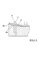
- FIGS. 16 and 17 show the configuration of the locking portion 142 according to the present embodiment.
- FIGS. 16 and 17 are views showing a vertical cross section of the arrow A3 portion of FIG. 12 from the arrow direction.
- FIG. 16 is a perspective view from above of the flat cable 102 and the slider 104 assembled, and
- FIG. It is a perspective view from the lower side of a single body.
- the locking portion 142 includes a digging portion 147 formed by being recessed from the mounting surface 145 toward the main body side (that is, the lower side) of the slider 104, and a digging portion 147.
- a flexible arm portion 148 that extends from the bottom portion 147b of the mounting surface 145 and protrudes from the protruding end of the arm portion 148.
- the slider 104 or the locking portion 142 is preferably made of an elastic material such as resin, for example.
- the slider 104 is provided with a pair of locking portions 142 (142a, 142b) at both ends in the width direction X corresponding to the openings 126 (126a, 126b) of the flat cable 102. ing.
- the configuration (shape, size, arrangement, etc.) of the locking portion 142 can be arbitrarily set as long as it can be locked to the opening 126.
- the width between the pair of locking portions 142 is set to be slightly smaller than the width between the pair of openings 126.
- the locking portion 142 has a protruding portion of the return portion 149 with respect to the arm portion 148 (in other words, on the opposite side of the digging portion 147 across the arm portion 148).
- the hole 151 is perforated along.
- the hole 151 passes through the slider 104 in the assembling direction Z with the flat cable 102.
- the arm portion 148 protrudes beyond the mounting surface 145 of the mounting portion 141 from the bottom portion 147b of the digging portion 147 toward the upper side in the assembly direction Z with the flat cable 102, in other words, the digging.
- the remaining portion of the bottom portion 147b of the insertion portion 147 is continuous with the slider 104.
- the digging portion 147 has a bottom portion 147 b and is configured as a hole portion that opens to the placement surface 145. Accordingly, the arm portion 148 can be bent and deformed toward the digging portion 147 side and the hole portion 151 side by falling into the digging portion 147 or the hole portion 151.
- the size of the digging portion 147 and the hole portion 151 in the length direction Y is set slightly larger than the width of the arm portion 148.
- the thickness of the remaining portion of the bottom portion 147b of the digging portion 147 that becomes a continuous portion of the arm portion 148 with the slider 104 that is, the base end portion of the arm portion 148), in other words, the digging portion 147.
- the hole 151 is a through hole that is perforated so as to penetrate the slider 104 in the assembly direction Z.
- the hole 151 has a bottom without penetrating the slider 104 and has a mounting surface 145. It is also possible to configure it as a hole that opens in (that is, the same configuration as the digging portion 147).
- the arm portion 148 has a size in the insertion direction of the flat cable 102 into the connector 106, that is, the size in the length direction Y (that is, the distance C6 shown in FIG. 15) in the opening 126 of the flat cable 102.
- the edge 27 is set to have substantially the same dimension (that is, C6 ⁇ B5) as the facing interval with respect to the longitudinal direction Y (that is, the distance B5 shown in FIG. 14A). Therefore, in a state where the arm portion 148 is inserted through the opening portion 126, the front and rear locking surfaces 148s of the locking portion 142 (specifically, the arm portion 148) are caused to interfere with the opposing edge portion 127, in other words. In this case, it can be held by the edge 127.
- the flat cable 102 can be reliably locked and positioned with respect to the slider 104 in the length direction Y (that is, the insertion direction of the flat cable 102 into the connector 106).
- the size of the arm portion 148 in the width direction X may be set slightly smaller than the facing interval of the edge portion 128 in the opening 126 of the flat cable 102 in the width direction X.
- the return portion 149 is provided so as to protrude outward from the protruding end of the arm portion 148 in the width direction X (that is, on the hole 151 side with respect to the arm portion 148).
- the return portion 149 has an inclined surface (hereinafter referred to as a pick-up portion) 149a that gradually inclines from the outside to the inside in the width direction X, and tapers toward the extending end of the arm portion 148. It is configured as follows.
- the pick-up portion 149a of the return portion 149 serves as a guide portion for the opening portion 126, and the opening portion 126 can be smoothly inserted into the return portion 149 and further to the arm portion 148.
- coated end part 124 in which the opening part 126 is formed is comprised only with the coating
- the return part 149 is provided so that it may protrude outside with respect to the width direction X
- the protrusion direction of the return part 149 is not limited to this.
- the arm portion 148 is configured to be able to bend and deform toward the digging portion 147 by falling into the digging portion 147, and by falling into the hole 151, the hole portion 151. It also has a configuration that can be bent and deformed to the side. Therefore, it is also possible to provide the return portion so as to protrude inward in the width direction X (that is, the digging portion 147 side with respect to the arm portion 148).
- the return portion can be configured to protrude in an arbitrary direction.
- the return portion protrudes forward or rearward with respect to the length direction Y.
- the return portion 149 is opposed to the placement portion 141 (in short, the placement surface 145) with an interval of the thickness of the flat cable 102 (that is, the distance T7 shown in FIG. 16). 149b.
- the return surface 149 b locks the opening 126 inserted through the arm portion 148.
- the return surface 149b has a surface of the covering end portion 124 of the upper covering portion 122 (in other words, in the vicinity of the edge portion 128 so that the opening 126 can be locked over the entire surface. )).
- the entire return surface 149b can be brought into close contact with the surface of the covering end portion 124 in a state where the arm portion 148 is inserted through the opening portion 126, and the opening portion 126 is securely locked by the return portion 149. Can do.
- the opening 126 and the locking portion 142 may be locked by an example of the following procedure. .
- the slider 104 is left still, and the flat cable 102 is positioned with respect to the slider 104 in the assembly direction Z (for example, the vertical direction).
- the mounting surface 145 of the mounting portion 141 of the slider 104 and the lower side of the terminal portion 123 of the flat cable 102 that is, the covering side (the non-exposed side) of the conductor 121 in the terminal portion 123) are directly opposed.
- the flat cable 102 is moved downward (as an example, downward in the vertical direction) while aligning the position of the opening 126 with the locking portion 142, specifically, the position of the pick-up portion 149 a of the return portion 149.
- the edge portion 128 (specifically, the outer edge portion 128a in the width direction X) of the opening 126 is brought into contact with the pick-up portion 149a. Then, a pressing force is applied to the flat cable 102 downward, the pressing force is applied to the return portion 149 from the edge portion 128a of the opening 126 via the pick-up portion 149a, and the arm portion 148 is moved in the width direction X. And bent inward (that is, the digging portion 147 side (in the direction of arrow A8 shown in FIG. 17 as an example)).
- the flat cable 102 is moved downward with the pressing force applied, so that the return portion 149 is inserted through the opening 126 while sliding the edge portion 128a along the pick-up portion 149a.
- the opening 126 is slightly expanded by elastic deformation due to the pressing force.
- the flat cable 102 is further moved downward until the terminal portion 123 comes into contact with the placement surface 145 of the placement portion 141 and is placed.
- the pressing force applied to the return portion 149 from the edge portion 128a of the opening 126 via the pick-up portion 149a is not applied, and the arm portion 148 moves in the width direction X.
- the arm portion 148 is inserted through the opening portion 126, and the front edge (that is, the end edge) of the terminal portion 123 abuts against the protrusion 43 of the placement portion 141, and the flat cable 102. Is positioned with respect to the slider 104.
- the opening 126 is locked with the return portion 149, and more specifically, the edge portion 128a of the opening 126 is locked with the return surface 149b of the return portion 149 (see FIG. 16). That is, the flat cable 102 and the slider 104 can be assembled in a state of being locked to each other (the state shown in FIG. 12). In this state, the front and rear locking surfaces 148 s of the arm portion 148 can interfere with the opposing edge portion 127 of the opening portion 126, in other words, can be held by the edge portion 127. As a result, the flat cable 102 can be reliably locked and positioned with respect to the slider 104 in the length direction Y (that is, the insertion direction of the flat cable 102 into the connector 106). Further, in this state, the conductor 121 of the terminal portion 123 in the flat cable 102 is exposed to the outside, and both end faces 29 in the width direction X of the terminal portion 123 are exposed to the outside.
- a force that separates the flat cable 102 and the slider 104 from each other in the assembling direction Z acts.
- an unlocking force for example, when an unlocking force is applied to move the flat cable 102 upward (as an example, upward in the vertical direction), the edge portion 128a of the opening 126 and the return surface 149b of the return portion 149 are applied. Interferes with each other, and a force is applied to bend and deform the arm portion 148 inward in the width direction X (that is, the digging portion 147 side (in the direction of arrow A8 shown in FIG. 17)).
- the flat cable 102 and the slider 104 can be separated from the assembled state. That is, the flat cable 102 and the slider 104 can be detachably assembled.
- the flat cable 102 assembled with the slider 104 is assembled with the connector 106 by inserting the slider 104 into the connector 106. Thereby, the flat cable 102 can be connected to another electric circuit via the connector 106.
- the connector 106 includes a housing 161 and a terminal portion 162 including a plurality of connection terminals provided in the housing 161.
- the housing 161 is made of, for example, an insulating resin material and has a fitting portion 163 for fitting the inserted flat cable 102.
- an accommodation groove for accommodating the terminal portion 162 extends in the length direction Y and is provided side by side in the width direction X.
- the fitting part 163 has a pair of wall part 64 for making the flat cable 102 inserted in the both ends of the width direction X contact and position.
- the distance between the pair of wall portions 164 in the width direction X is set to be slightly larger than the distance between both end surfaces 129 of the terminal portion 123.
- the housing 161 is provided with a locking claw 165 for preventing the flat cable 102 from being detached by being inserted into the fitting portion 163 and fitted (that is, connected to the connector 106). Accordingly, the flat cable 102 can be held in a state of being connected to the connector 106 by locking the locking claw 165 to the connector locking portion 146 of the slider 104 assembled to the flat cable 102.
- the terminal portion 162 is accommodated in the fitting portion 163 with the connection terminals aligned with the receiving grooves of the fitting portion 163 and the connection terminals facing the outside.
- the number of connection terminals of the terminal portion 162 corresponds to the number of conductors 121 exposed at the terminal portion 123 of the flat cable 102.
- the terminal portion 123 is inserted into the fitting portion 163 and the locking claw 165 is inserted into the connector locking portion 146 according to an example of the following procedure. What is necessary is just to lock.
- the flat cable 102 is attached to the connector 106 so that the conductor 121 exposed to the terminal portion 123 of the flat cable 102 can come into contact with the terminal portion 162 exposed to the outside in the fitting portion 163 of the connector 106. Position with respect to. From this state, the terminal portion 123 is inserted into the fitting portion 163. At that time, the flat cable 102 is positioned with respect to the connector 106 while the both end surfaces 29 of the terminal portion 123 are brought into contact with the wall portion 64. Then, the terminal portion 123 is inserted into the fitting portion 163 until the locking claw 165 is locked to the connector locking portion 146.
- the conductor 121 of the terminal part 123 can be contacted with the terminal part 162 of the connector 106, and the flat cable 102 and the connector 106 can be electrically connected.
- the electrical connection state between the flat cable 102 and the connector 106 can be held by the locking of the connector locking portion 146 and the locking claw 165.
- the flat cable 102 can be connected to another electric circuit via the connector 106.
- the flat cable 102 and the slider 104 can be easily engaged only by locking the opening 126 with the locking portion 142 (specifically, the return portion 149). Can be assembled.
- a terminal connection tool serving as an interface for connecting the flat cable 102 to the connector 106 can be configured by only the slider 104. Therefore, the flat cable 102 and the slider 104 can be directly assembled.
- the flat cable 102 does not have to be assembled with the slider 104 via a cover member or the like. Thereby, the assembly work load of the flat cable 102 and the terminal connector can be reduced.
- FIGS. 10 to 12 show, as an example, a configuration in which the opening 126a and the locking portion 142a are arranged farther from the terminal portion 123 in the longitudinal direction Y than the opening 126b and the locking portion 142b. .
- the locking direction of the flat cable 102 with respect to the slider 104 can be uniquely determined. Specifically, a state where the lower side of the terminal portion 123 (that is, the covering side (the non-exposed side) of the conductor 121 in the terminal portion 123) is directly opposed to the mounting surface 145 of the mounting portion 141 (FIG. 10). Only in the state shown), the openings 126a and 126b can be locked with the locking portions 142a and 142b, respectively. This prevents erroneous placement of the terminal portion 123 with respect to the placement portion 141, that is, an assembly error with respect to the slider 104 of the flat cable 102.
- one opening portion and the locking portion may have a larger rectangle in the length direction Y or the width direction X than the other opening portion and the locking portion, or one may be circular and the other may be elliptical. That's fine.
- the digging portion 147 (that is, the hole portion of the placement portion 141) is formed in order to give the arm portion 148 sufficient flexibility.
- the arm portion 148 is configured to protrude from the placement surface 145 in the assembling direction Z with the flat cable 102.
- 18 and 19 are views showing a longitudinal section corresponding to the arrow A3 portion of FIG. 12 from the direction of the arrow, and FIG. 18 is a perspective view from above of the state in which the flat cable 102 and the slider 104 are assembled. 19 is a perspective view from below of the slider 104 alone.
- the slider 104 (corresponding to the flexible aggregated wiring connector of the first embodiment) according to the second embodiment is a terminal part 123 of the flat cable 102 (corresponding to the flexible aggregated wiring of the first embodiment). Used when inserting and connecting to the connector 106 of the connection partner.
- the slider 104 includes a placement surface 145 on which the terminal portion 123 and the covering portion 122 are placed, and a pair of locking portions 142 (142a, 142b) formed on both ends in the width direction of the placement surface 145. (Corresponding to the locking hook of the first embodiment).
- the pair of locking portions 142 (142a, 142b) is formed of a pair of openings 126 (126a, 126b) (both the locking holes of the first embodiment) drilled on both ends in the width direction of the covering portion 122, respectively. To the corresponding).
- the width between the pair of locking portions 142 is slightly smaller than the width between the pair of opening portions 126.
- the locking portion 142 extends from the digging portion 147 formed on the placement surface 145 and the bottom portion 147b of the digging portion 147, and is described above.
- a flexible arm portion 148 that protrudes from the mounting surface 145, and a return portion 149 that protrudes from the protruding end of the arm portion 148 and locks the opening 126. is doing.
- the assembly structure according to the second embodiment includes a flat cable 102 including a conductor 121 and a pair of covering portions 122 that sandwich the conductor 121, and a slider 104 that inserts the flat cable 102 into a connector 106 for connection.
- the flat cable 102 includes an opening 126 formed so as to penetrate the covering portion 122.
- the slider 104 is formed so as to protrude from the placement surface 145 on which the terminal portion 123 of the flat cable 102 is placed, and the placement surface 145 of the terminal portion on the placement surface 145, and the flat cable 102 is And a locking portion 142 for locking.
- the locking portion 142 protrudes from the placement surface 145 from the digging portion 147 formed to be recessed from the placement surface 145 toward the main body of the slider 104 and the bottom portion 147b of the digging portion 147. And a flexible arm portion 148 and a return portion 149 projecting from the projecting end of the arm portion 148 and locking the opening 126.
- the flat cable 102 is directly and easily assembled to the slider 104 by locking the opening 126 of the flat cable 102 with the locking portion 142 (specifically, the return portion 149) of the slider 104. be able to.
- the flat cable 102 and the slider 104 can be separated from the assembled state. That is, the flat cable 102 and the slider 104 can be detachably assembled. As a result, in addition to suppressing the flat cable 102 from being bent in the direction opposite to the placement surface 145, the assembly work load between the flat cable 102 and the terminal connector can be reduced.
- the flexible concentrated wiring connector according to the present invention is useful in that it is possible to suppress the flexible concentrated wiring from being bent in the direction opposite to the mounting surface.
Landscapes
- Coupling Device And Connection With Printed Circuit (AREA)
Description
(1) フレキシブル集約配線の端末部を接続相手のコネクタに挿入接続する際に用いるフレキシブル集約配線コネクタであって、
前記端末部が載置される載置面と、
該載置面の幅方向における両端側それぞれに形成された一対の係止フックと、を備え、
前記一対の係止フックは、前記端末部の幅方向における両端側それぞれに穿設された一対の係止孔に係合する。
(2) 上記(1)のフレキシブル集約配線コネクタであって、
前記一対の係止フック間の幅は、前記一対の係止孔間の幅よりも僅かに小さい。
(3) 上記(1)又は(2)のフレキシブル集約配線コネクタであって、
前記載置面の幅方向における両端それぞれには、突部が形成されている。
(4) 上記(1)~(3)のいずれか1つのフレキシブル集約配線コネクタであって、
前記載置面の幅方向における両端側それぞれには、中央側から両端側へ向かうに従い突出量が大きくなるように傾斜するテーパ部が形成されている。
(5) 上記(1)~(4)のいずれか1つのフレキシブル集約配線コネクタであって、
前記係止フックは、
前記載置面に形成された掘り込み部と、
前記掘り込み部の底部から延出され、前記載置面よりも突出するように形成された、可撓性を有するアーム部と、
前記アーム部の突出端から突設され、前記係止孔を係止する返し部と、を有している。
以下、第1実施形態におけるフレキシブル集約配線コネクタを図1~図5に基づいて詳細に説明する。
(1) 第1実施形態に係るフレキシブル集約配線コネクタ11は、フレキシブル集約配線12の端末部13を接続相手のコネクタに挿入接続する際に用いる。フレキシブル集約配線コネクタ11は、前記端末部13が載置される載置面14と、該載置面14の幅方向における両端側それぞれに形成された一対の係止フック17、17と、を備えている。前記一対の係止フック17、17は、前記端末部13の幅方向における両端側それぞれに穿設された一対の係止孔12a、12bに係合する。
(2) 第1実施形態に係るフレキシブル集約配線コネクタ1では、前記一対の係止フック17、17間の幅は、前記一対の係止孔12a、12b間の幅よりも僅かに小さい。
(3) 第1実施形態に係るフレキシブル集約配線コネクタ1では、前記載置面14の幅方向における両端それぞれには、突部14bが形成されている。
(4) 第1実施形態に係るフレキシブル集約配線コネクタ1では、前記載置面14の幅方向における両端側それぞれには、中央側から両端側へ向かうに従い突出量が大きくなるように傾斜するテーパ部14aが形成されている。
(5) 第1実施形態に係るフレキシブル集約配線コネクタ1では、前記係止フック17、17は、前記載置面14に形成された掘り込み部18と、前記掘り込み部18の底部18aから延出され、前記載置面14よりも突出するように形成された、可撓性を有する基部17a(アーム部)と、前記基部17aの突出端から突設され、前記係止孔12a、12bを係止する突起部17b(返し部)と、を有している。
次に、フラットケーブルと該フラットケーブルを接続用のコネクタに挿入させる際のガイド部材(すなわち、スライダ。)とを組み付けるための組み付け構造に関する第2実施形態について説明する。
(1) 第2実施形態に係るスライダ104(第1実施形態のフレキシブル集約配線コネクタと対応する。)は、フラットケーブル102(第1実施形態のフレキシブル集約配線と対応する。)の端末部123を接続相手のコネクタ106に挿入接続する際に用いる。スライダ104は、前記端末部123及び被覆部122が載置される載置面145と、該載置面145の幅方向における両端側それぞれに形成された一対の係止部142(142a、142b)(第1実施形態の係止フックと対応する。)と、を備えている。前記一対の係止部142(142a、142b)は、前記被覆部122の幅方向における両端側それぞれに穿設された一対の開口部126(126a、126b)(第1実施形態の係止孔と対応する。)に係合する。
(2) 第2実施形態に係るスライダ104では、前記一対の係止部142間の幅は、前記一対の開口部126間の幅よりも僅かに小さい。
(3) 第2実施形態に係るスライダ104では、前記係止部142は、前記載置面145に形成された掘り込み部147と、前記掘り込み部147の底部147bから延出され、前記載置面145よりも突出するように形成された、可撓性を有するアーム部148と、前記アーム部148の突出端から突設され、前記開口部126を係止する返し部149と、を有している。
(4) 第2実施形態に係る組み付け構造は、導体121と前記導体121を挟む一対の被覆部122とを備えたフラットケーブル102と、前記フラットケーブル102を接続用のコネクタ106に挿入させるスライダ104との組み付け構造である。前記フラットケーブル102は、前記被覆部122を貫通させて形成された開口部126を備えている。前記スライダ104は、前記フラットケーブル102の端末部123を載置する載置面145と、前記載置面145における前記端末部の載置面145よりも突出させて形成され、前記フラットケーブル102を係止する係止部142とを備えている。前記係止部142は、前記載置面145から前記スライダ104の本体側に凹ませて形成された掘り込み部147と、前記掘り込み部147の底部147bから前記載置面145よりも突出させて形成され、可撓性を有するアーム部148と、前記アーム部148の突出端から突設され、前記開口部126を係止する返し部149とを有して構成される。
これによれば、フラットケーブル102の開口部126をスライダ104の係止部142(具体的には、返し部149。)と係止させることで、フラットケーブル102をスライダ104と直接かつ容易に組み付けることができる。また、フラットケーブル102とスライダ104を相互に組み付けられた状態から分離させることも可能となる。すなわち、フラットケーブル102とスライダ104を着脱可能に組み付けることができる。
この結果、フラットケーブル102が載置面145と反対方向にたわむことを抑制することに加えて、フラットケーブル102と端末接続具との組み付け作業負荷の軽減化を図ることができる。
12…フレキシブル集約配線
12a、12b…係止孔
13…端末部
14…載置面
14a…テーパ部
14b…突部
17…係止フック
17a…基部(アーム部)
17b…突起部(返し部)
18…掘り込み部
18a…底部
102…フラットケーブル(フレキシブル集約配線)
104…スライダ(フレキシブル集約配線コネクタ)
106…コネクタ
121…導体
122…被覆部
123…端末部
126…開口部(係止孔)
141…載置部
142…係止部(係止フック)
145…載置面
147…掘り込み部
147b…底部
148…アーム部
149…返し部
Claims (5)
- フレキシブル集約配線の端末部を接続相手のコネクタに挿入接続する際に用いるフレキシブル集約配線コネクタであって、
前記端末部が載置される載置面と、
該載置面の幅方向における両端側それぞれに形成された一対の係止フックと、を備え、
前記一対の係止フックは、前記端末部の幅方向における両端側それぞれに穿設された一対の係止孔に係合する、
フレキシブル集約配線コネクタ。 - 前記一対の係止フック間の幅は、前記一対の係止孔間の幅よりも僅かに小さい、
請求項1に記載のフレキシブル集約配線コネクタ。 - 前記載置面の幅方向における両端それぞれには、突部が形成されている、
請求項1又は請求項2に記載のフレキシブル集約配線コネクタ。 - 前記載置面の幅方向における両端側それぞれには、中央側から両端側へ向かうに従い突出量が大きくなるように傾斜するテーパ部が形成されている、
請求項1~請求項3のいずれか1項に記載のフレキシブル集約配線コネクタ。 - 前記係止フックは、
前記載置面に形成された掘り込み部と、
前記掘り込み部の底部から延出され、前記載置面よりも突出するように形成された、可撓性を有するアーム部と、
前記アーム部の突出端から突設され、前記係止孔を係止する返し部と、を有している、
請求項1~請求項4のいずれか1項に記載のフレキシブル集約配線コネクタ。
Priority Applications (4)
| Application Number | Priority Date | Filing Date | Title |
|---|---|---|---|
| DE201311003215 DE112013003215T5 (de) | 2012-06-27 | 2013-06-21 | Flexibler Mehrdraht-Steckverbinder |
| KR20147036203A KR20150011395A (ko) | 2012-06-27 | 2013-06-21 | 플랙시블 멀티배선 커넥터 |
| CN201380034782.4A CN104412459B (zh) | 2012-06-27 | 2013-06-21 | 柔性多线连接器 |
| US14/553,193 US9337560B2 (en) | 2012-06-27 | 2014-11-25 | Connector having a mounting surface with engagement hooks offset from each other in an insertion direction of a flexible integrated wiring |
Applications Claiming Priority (4)
| Application Number | Priority Date | Filing Date | Title |
|---|---|---|---|
| JP2012143597A JP5985271B2 (ja) | 2012-06-27 | 2012-06-27 | フレキシブル集約配線コネクタ |
| JP2012-143597 | 2012-06-27 | ||
| JP2012-148742 | 2012-07-02 | ||
| JP2012148742A JP6103836B2 (ja) | 2012-07-02 | 2012-07-02 | フラットケーブルとスライダとの組み付け構造 |
Related Child Applications (1)
| Application Number | Title | Priority Date | Filing Date |
|---|---|---|---|
| US14/553,193 Continuation US9337560B2 (en) | 2012-06-27 | 2014-11-25 | Connector having a mounting surface with engagement hooks offset from each other in an insertion direction of a flexible integrated wiring |
Publications (1)
| Publication Number | Publication Date |
|---|---|
| WO2014002889A1 true WO2014002889A1 (ja) | 2014-01-03 |
Family
ID=49783045
Family Applications (1)
| Application Number | Title | Priority Date | Filing Date |
|---|---|---|---|
| PCT/JP2013/067073 Ceased WO2014002889A1 (ja) | 2012-06-27 | 2013-06-21 | フレキシブル集約配線コネクタ |
Country Status (5)
| Country | Link |
|---|---|
| US (1) | US9337560B2 (ja) |
| KR (1) | KR20150011395A (ja) |
| CN (1) | CN104412459B (ja) |
| DE (1) | DE112013003215T5 (ja) |
| WO (1) | WO2014002889A1 (ja) |
Families Citing this family (2)
| Publication number | Priority date | Publication date | Assignee | Title |
|---|---|---|---|---|
| DE102021128888B4 (de) | 2021-11-05 | 2025-01-30 | Erni International Ag | Steckverbinder, Steckverbinderanordnung und Verfahren zur Herstellung des Steckverbinders |
| DE102024202736A1 (de) * | 2024-03-22 | 2025-09-25 | Yamaichi Electronics Deutschland Gmbh | Flachsteckverbinder, Flachsteckverbindersystem und Verfahren zur Herstellung eines Flachsteckverbinders |
Citations (4)
| Publication number | Priority date | Publication date | Assignee | Title |
|---|---|---|---|---|
| JPH0216587U (ja) * | 1988-07-18 | 1990-02-02 | ||
| JP2002100425A (ja) * | 2000-09-25 | 2002-04-05 | Calsonic Kansei Corp | フレキシブルフラットケーブル用コネクタ |
| JP2006085989A (ja) * | 2004-09-15 | 2006-03-30 | Molex Inc | Ffc用挿入ガイド |
| JP2009011380A (ja) * | 2007-06-29 | 2009-01-22 | Sansei R & D:Kk | 遊技機 |
Family Cites Families (12)
| Publication number | Priority date | Publication date | Assignee | Title |
|---|---|---|---|---|
| US5486117A (en) * | 1994-08-09 | 1996-01-23 | Molex Incorporated | Locking system for an electrical connector assembly |
| JPH10312841A (ja) * | 1997-05-09 | 1998-11-24 | Thomas & Betts Corp <T&B> | 可撓性フラットケーブル用コネクタ |
| JP3144413B2 (ja) | 1999-04-12 | 2001-03-12 | 松下電器産業株式会社 | フレキシブルケーブル挿入接続装置 |
| US6398577B1 (en) * | 2000-10-04 | 2002-06-04 | Molex Incorporated | Latching/unlatching system for electrical connectors |
| US7040910B2 (en) * | 2001-08-02 | 2006-05-09 | Hosiden Corporation | Plug type connector |
| JP4480185B2 (ja) * | 2007-11-16 | 2010-06-16 | 日本航空電子工業株式会社 | コネクタ |
| CN101874328A (zh) * | 2007-11-29 | 2010-10-27 | Fci连接器新加坡有限公司 | 柔性印刷电路板的电连接器 |
| JP4247798B1 (ja) * | 2008-05-15 | 2009-04-02 | 株式会社旭電化研究所 | コネクタ構造 |
| JP5213537B2 (ja) | 2008-06-18 | 2013-06-19 | 矢崎総業株式会社 | フレキシブル集約配線の端末接続具及びその組み付け方法 |
| JP5325699B2 (ja) | 2009-08-07 | 2013-10-23 | 矢崎総業株式会社 | フレキシブル集約配線コネクタ |
| JP5469958B2 (ja) | 2009-08-24 | 2014-04-16 | 矢崎総業株式会社 | フレキシブル集約配線コネクタ |
| JP5090506B2 (ja) | 2010-08-18 | 2012-12-05 | 日本航空電子工業株式会社 | コネクタ |
-
2013
- 2013-06-21 KR KR20147036203A patent/KR20150011395A/ko not_active Withdrawn
- 2013-06-21 DE DE201311003215 patent/DE112013003215T5/de active Pending
- 2013-06-21 CN CN201380034782.4A patent/CN104412459B/zh active Active
- 2013-06-21 WO PCT/JP2013/067073 patent/WO2014002889A1/ja not_active Ceased
-
2014
- 2014-11-25 US US14/553,193 patent/US9337560B2/en active Active
Patent Citations (4)
| Publication number | Priority date | Publication date | Assignee | Title |
|---|---|---|---|---|
| JPH0216587U (ja) * | 1988-07-18 | 1990-02-02 | ||
| JP2002100425A (ja) * | 2000-09-25 | 2002-04-05 | Calsonic Kansei Corp | フレキシブルフラットケーブル用コネクタ |
| JP2006085989A (ja) * | 2004-09-15 | 2006-03-30 | Molex Inc | Ffc用挿入ガイド |
| JP2009011380A (ja) * | 2007-06-29 | 2009-01-22 | Sansei R & D:Kk | 遊技機 |
Also Published As
| Publication number | Publication date |
|---|---|
| KR20150011395A (ko) | 2015-01-30 |
| CN104412459B (zh) | 2017-11-10 |
| CN104412459A (zh) | 2015-03-11 |
| US20150079831A1 (en) | 2015-03-19 |
| DE112013003215T5 (de) | 2015-04-02 |
| US9337560B2 (en) | 2016-05-10 |
Similar Documents
| Publication | Publication Date | Title |
|---|---|---|
| US12191592B2 (en) | Connector and connector assembly | |
| KR101985141B1 (ko) | 커넥터 | |
| US8292648B2 (en) | Flexible cable connecting structure and flexible cable connector | |
| JP5943774B2 (ja) | コネクタ | |
| CN103098307B (zh) | 板对板连接器 | |
| CN111934110A (zh) | 连接器 | |
| US10581184B2 (en) | Low-profile board-to-board connector, mating connector, and connector assembly | |
| CN202817366U (zh) | 板对板连接器 | |
| CN104934818A (zh) | 连接器 | |
| JP5460037B2 (ja) | 電線対基板コネクタ | |
| CN105580212B (zh) | 连接器 | |
| JP7655777B2 (ja) | 端子、電線コネクタ及び電線対基板コネクタ | |
| CN102474029A (zh) | 柔性集中配线连接器 | |
| JP2018081940A (ja) | コネクタ | |
| US9337560B2 (en) | Connector having a mounting surface with engagement hooks offset from each other in an insertion direction of a flexible integrated wiring | |
| JP6002636B2 (ja) | フラットケーブル端末接続具 | |
| US9755339B2 (en) | Connecting structure of connector and flat circuit body | |
| JP6103836B2 (ja) | フラットケーブルとスライダとの組み付け構造 | |
| JP5979418B2 (ja) | 電気コネクタ | |
| JP5081079B2 (ja) | フレキシブル集約配線コネクタ | |
| TWI919401B (zh) | 連接器模組及電子機器 | |
| JP5985271B2 (ja) | フレキシブル集約配線コネクタ | |
| KR101160901B1 (ko) | 한쌍의 헤더 콘택트 및 이것을 이용한 헤더 커넥터 | |
| JP4931441B2 (ja) | ケーブル接続用コネクタ | |
| JP2025141469A (ja) | コネクタ及びコネクタ対 |
Legal Events
| Date | Code | Title | Description |
|---|---|---|---|
| 121 | Ep: the epo has been informed by wipo that ep was designated in this application |
Ref document number: 13809043 Country of ref document: EP Kind code of ref document: A1 |
|
| ENP | Entry into the national phase |
Ref document number: 20147036203 Country of ref document: KR Kind code of ref document: A |
|
| WWE | Wipo information: entry into national phase |
Ref document number: 112013003215 Country of ref document: DE Ref document number: 1120130032155 Country of ref document: DE |
|
| 122 | Ep: pct application non-entry in european phase |
Ref document number: 13809043 Country of ref document: EP Kind code of ref document: A1 |