WO2014002621A1 - 取引装置及びプログラムを格納する記憶媒体 - Google Patents
取引装置及びプログラムを格納する記憶媒体 Download PDFInfo
- Publication number
- WO2014002621A1 WO2014002621A1 PCT/JP2013/063191 JP2013063191W WO2014002621A1 WO 2014002621 A1 WO2014002621 A1 WO 2014002621A1 JP 2013063191 W JP2013063191 W JP 2013063191W WO 2014002621 A1 WO2014002621 A1 WO 2014002621A1
- Authority
- WO
- WIPO (PCT)
- Prior art keywords
- transaction
- user
- unit
- medium
- transactions
- Prior art date
- Legal status (The legal status is an assumption and is not a legal conclusion. Google has not performed a legal analysis and makes no representation as to the accuracy of the status listed.)
- Ceased
Links
Images


Classifications
-
- G—PHYSICS
- G06—COMPUTING OR CALCULATING; COUNTING
- G06Q—INFORMATION AND COMMUNICATION TECHNOLOGY [ICT] SPECIALLY ADAPTED FOR ADMINISTRATIVE, COMMERCIAL, FINANCIAL, MANAGERIAL OR SUPERVISORY PURPOSES; SYSTEMS OR METHODS SPECIALLY ADAPTED FOR ADMINISTRATIVE, COMMERCIAL, FINANCIAL, MANAGERIAL OR SUPERVISORY PURPOSES, NOT OTHERWISE PROVIDED FOR
- G06Q20/00—Payment architectures, schemes or protocols
- G06Q20/08—Payment architectures
- G06Q20/18—Payment architectures involving self-service terminals [SST], vending machines, kiosks or multimedia terminals
-
- G—PHYSICS
- G07—CHECKING-DEVICES
- G07F—COIN-FREED OR LIKE APPARATUS
- G07F19/00—Complete banking systems; Coded card-freed arrangements adapted for dispensing or receiving monies or the like and posting such transactions to existing accounts, e.g. automatic teller machines
- G07F19/20—Automatic teller machines [ATMs]
Definitions
- the present invention relates to a transaction apparatus and a program, and can be applied to, for example, an ATM (Automatic Teller Machine) installed in a financial institution such as a bank or a convenience store.
- ATM Automatic Teller Machine
- a cash card is inserted from a customer, and authentication is performed by biometric authentication using a personal identification number or biometric information (for example, information such as palm print, fingerprint, vein). Transactions are performed after processing (identity verification).
- biometric authentication using a personal identification number or biometric information (for example, information such as palm print, fingerprint, vein).
- the ATM corresponding to the transaction with the conventional card if the customer does not operate for a certain period of time, the cash card is returned (discharged) and the transaction is stopped.
- the customer who uses the ATM has a willingness to receive the cash card inserted in the ATM, so it is not possible to leave the ATM without receiving the cash card by his / her own intention (without terminating the transaction). rare.
- cash and a cash card are discharged at the end of the transaction, but the transaction itself is ended even if these are forgotten.
- the first aspect of the present invention is a transaction apparatus for performing transactions with a user, (1) a medium use transaction for performing a transaction with the user using a medium in which information regarding the transaction is recorded, and a medium in which information regarding the transaction is recorded.
- a transaction processing unit corresponding to a medium non-use transaction in which a transaction with the user is performed without using (2) a case where the transaction processing unit is performing a medium use transaction, and The user is monitored by selecting a different monitoring method depending on whether or not a user transaction is being performed, and when the user detects that he / she has left the periphery of the transaction apparatus, the transaction unit performs control to stop the transaction. And a transaction control unit.
- a transaction processing unit capable of performing a transaction with the user without using a medium in which information related to the transaction is recorded;
- a user detection unit that can detect whether or not the user exists in the vicinity of the transaction device, and
- a medium A transaction control unit that controls to stop the transaction by the transaction unit when the user cannot be detected by the user detection unit while performing the transaction with the user.
- a transaction program provides a computer installed in a transaction apparatus that performs a transaction with a user, (1) a medium use transaction that performs a transaction with the user using a medium in which information related to the transaction is recorded; A transaction processing unit corresponding to a medium non-use transaction in which a transaction with the user is performed without using a medium on which information related to the transaction is recorded; and (2) the transaction processing unit is performing a medium use transaction;
- the transaction processing unit conducts a medium non-use transaction, a different monitoring method is selected to monitor the user, and when the user detects that the user has left the periphery of the transaction device, the transaction unit It is made to function as a transaction control part which performs control which cancels the transaction by.
- the transaction program according to the fourth aspect of the present invention is capable of (1) performing a transaction with the user without using a medium in which information related to the transaction is recorded, using a computer installed in a transaction apparatus that performs the transaction with the user.
- FIG. 2 is a block diagram showing the overall configuration of a transaction system 1000 having ATM 1 of this embodiment.
- an ATM 1, an application server 2, a host computer 3, a DB server 4, and an authentication server 5 are arranged.
- positioned in the transaction system 1000 is not limited.
- the user who operates ATM1 is a customer, but the user who operates ATM1 is not limited to a customer such as a staff member of a financial institution, for example.
- the ATM1 is connected to the network N.
- the ATM 1 is connected to the application server 2 via the network N.
- the application server 2 can be connected to the host computer 3, the DB server 4, and the authentication server 5, and provides transaction processing services to the ATM 1 in cooperation with these devices.
- the system constituted by the application server 2, the host computer 3, the DB server 4, and the authentication server 5 is recognized as one external system.
- the specific hardware configuration of the external system described above is not limited.
- the external system may be configured using a single device (computer).
- the communication method of the network N is not limited, for example, an IP communication network such as the Internet can be applied.
- the application server 2 and other servers are faster than the ATM 1 by, for example, LAN connection (for example, Ethernet (registered trademark) connection). It is assumed that proper communication is possible.
- FIG. 1 is a block diagram showing the overall configuration of the ATM 1 of this embodiment.
- FIG. 3 is an external perspective view of the ATM 3.
- the ATM 1 includes a control unit 10, a data storage unit 20, a user interface unit 30, a card reader 40, a printer 50, a cash processing unit 60, and a proximity sensor 70.
- the ATM 1 of the first embodiment supports cardless transactions in addition to transactions using cash cards.
- the control part 10 bears the function (functions, such as the transaction processing part of the embodiment, a transaction control part, a non-operation timekeeping part) of performing operation control and information processing of each part in ATM1.
- the control unit 10 includes a transaction processing unit 110 and a communication unit 120.
- the data storage unit 20 is a data storage unit that stores various types of information necessary for the control unit 10 to perform information processing.
- the data storage unit 20 can be configured by various memories, for example.
- the control unit 10 can be realized, for example, by installing the transaction program of the embodiment (a program including the processing configuration of the transaction processing unit 110) or the like in an implementation configuration (computer) of a program including a processor or the like.
- the above-described transaction program may be stored in the data storage unit 20 and read and executed by the control unit 10 when the ATM 1 is activated.
- the communication unit 120 is a network interface for connecting to the network N.
- the communication unit 120 can be the same as the existing ATM or the like, and will not be described in detail.
- the transaction processing unit 110 performs information processing (including information presented to the customer and processing associated with operation reception) for performing transactions with the customer, and controls each component in the ATM 1 in accordance with the transaction processing. It is.
- the user interface unit 30 is responsible for the user interface function of the ATM 1.
- the user interface unit 30 cooperates with the control unit 10 to realize an operation reception unit.
- the user interface unit 30 of this embodiment is equipped with an operation display unit 31 and a biological information acquisition unit 32 as devices of a user interface.
- the operation display unit 31 can present an operation screen to the customer by using a touch panel display or the like, and can perform information output to the customer and operation reception from the customer (menu selection, amount input, number input, etc.). It is a device.
- the biometric information acquisition unit 32 as a biometric information acquisition unit is an interface for acquiring biometric information from a customer.
- the biometric information acquisition unit 32 captures the customer's palm (palmprint) with a scanner 321 (see FIG. 3) disposed on the front surface of the ATM 1 and captures the captured image data (palmprint image data). It shall be held as biological information.
- Data processing (such as a palmprint image data generation method) performed by the scanner 321 and the biometric information acquisition unit 32 can be applied to the same device as that used in the existing palm authentication, and detailed description thereof is omitted.
- Information used for biometric authentication in transaction system 1000 is not limited to palm prints, and other biometric information such as fingerprints, eyeball glows, voice prints, hand veins, and the like can be applied.
- the card reader 40 reads data of the cash card inserted into the card insertion / extraction port 401 from the customer.
- the card reader 40 can be the same as the existing ATM or the like, and will not be described in detail.
- the printer 50 prints a statement or the like on which transaction details are printed and discharges it from the slip discharge unit 501. Note that the printer 50 itself can be the same as the existing ATM or the like, and will not be described in detail.
- the cash processing unit 60 has a function of storing cash (banknotes and / or coins) received from the customer and a function of withdrawing the stored cash to the customer.
- the cash processing part 60 can apply the same thing as the existing ATM etc.
- the cash processing unit 60 includes a banknote storage unit 610 that stores banknotes and a coin storage unit 620 that stores coins.
- banknotes can be deposited / withdrawn from a banknote deposit / withdrawal port 611 shown in FIG.
- the coin storage part 620 it is possible to deposit / withdraw coins from a coin deposit / withdrawal port 621 shown in FIG.
- the proximity sensor 70 (human sensor) is a sensor for detecting the presence or absence of a customer in the vicinity of the ATM 1.
- the proximity sensor 70 detects a customer under the control of the control unit 10 and reports the detection result to the control unit 10. That is, the proximity sensor 70 realizes a user detection unit in cooperation with the control unit 10.
- the hardware configuration of the proximity sensor 70 is not limited. For example, a sensor using ultrasonic waves, visible light, infrared rays, or the like can be applied.
- Application server 2 is responsible for the interface function with ATM 1 in the external system described above.
- the application server 2 can be constructed by installing an application program or the like in an information processing apparatus (computer) such as C or a workstation. Specific processing contents performed by the application server 2 will be described in detail in the operation description to be described later.
- the authentication server 5 collates the biometric information registered in the registered authentication information storage unit 51 and returns the collation result to the application server 2.
- the authentication server 5 can be constructed by installing an authentication processing program or the like in an information processing apparatus (computer) such as a PC or a workstation. Note that the biometric information collation process itself performed by the authentication server 5 can be applied to the same process as that of an existing biometric authentication apparatus.
- FIG. 4 is an explanatory diagram showing a configuration example of the registration authentication information storage unit 51.
- biometric information identifier an identifier functioning as a label of the biometric information
- each biological information is represented as “biological information BD1, biological information BD2,...”, But actually, the biological information data itself and the link destination to the data (File name etc.) etc. are registered.
- “biological information BD1” corresponds to the biometric information identifier “10001”.
- the format of the biometric information registered in the registered authentication information storage unit 51 is not limited as long as it can be used for authentication processing (collation processing). For example, it is extracted from palmprint image data or palmprint images. It may be feature amount data.
- the DB server 4 When the date of birth information is input from the application server 2, the DB server 4 obtains customer information (including account information and biometric information identifier) corresponding to the date of birth from the account correspondence information storage unit 41. It detects and returns the detection result to the application server 2.
- the DB server 4 can be constructed, for example, by accumulating data having a data structure described later in an existing DB server.
- FIG. 5 is an explanatory diagram showing a configuration example of the account correspondence information storage unit 41.
- At least “account number”, “biological information identifier” of the customer of the account, and “birth date” of the customer of the account are registered for each account. Yes.
- the DB server 4 detects an account (account number) corresponding to the date of birth from the account correspondence information storage unit 41, and all the detected accounts Information related to (including the account number and biometric information identifier) is returned to the application server 2.
- the host computer 3 for example, a host computer capable of transaction processing using ATM at an existing financial institution can be applied.
- FIGS. 6 to 8 are sequence diagrams showing operations (including the operation of ATM1) when a cardless transaction is performed in the transaction system 1000.
- FIG. 6 to 8 illustrate an example in which a cardless transaction using authentication based on biometric information is performed in ATM1.
- FIGS. 6 to 8 show an example in which a withdrawal transaction is continuously performed from the balance inquiry.
- transaction method selection screen for selecting a transaction method (transaction using a cash card or cardless transaction) displayed on the operation display unit 31 of the ATM 1 It is assumed that the cardless transaction is selected by (S101).
- FIG. 10 is an explanatory diagram showing a configuration example of a transaction method selection screen displayed on the screen of the operation display unit 31.
- a button B101 for starting a transaction using a cash card (a button labeled “Transaction with card”) and a button B102 for starting a cardless transaction (“Cardless” A button labeled “Transaction”.
- Cardless A button labeled “Transaction”.
- the control unit 10 of the ATM 1 causes the customer to select a transaction content (hereinafter referred to as “transaction selection screen”), It is displayed on the operation display unit 31 (S102).
- FIG. 11 is an explanatory diagram showing a configuration example of a transaction selection screen displayed on the screen of the operation display unit 31.
- a button B201 (a button labeled “withdrawal”) for starting a withdrawal transaction withdrawing from the customer's account, and a deposit transaction for depositing (depositing) into the customer's account
- Button B202 (a button labeled “deposit”) for starting the transaction
- a button B203 (a button labeled “balance inquiry”) for starting a balance inquiry transaction for inquiring the balance of the customer's account And are arranged.
- the button B203 for starting the transaction of balance inquiry is pressed by the customer.
- biometric information input acceptance screen Is displayed on the operation display unit 31 (S103).
- FIG. 12 is an explanatory diagram showing a configuration example of a biometric information input acceptance screen displayed on the screen of the operation display unit 31.
- the biometric information input acceptance screen of FIG. 12 messages prompting the customer to input biometric information (press the palm against the scanner 321 of the biometric information acquisition unit 32) (in FIG. 12, “read biometric information”, “right side of entire device” And a transaction stop button B301 for accepting the transaction stoppage are arranged.
- biometric information pressing the palm against the scanner 321 of the biometric information acquisition unit 32
- palmprint image data is acquired as the biometric information of the customer by the biometric information acquisition unit 32.
- control unit 10 of the ATM 1 causes the operation display unit 31 to display a screen for allowing the customer to input the date of birth (hereinafter referred to as “birth date input acceptance screen”) (S104).
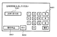
- FIG. 13 is an explanatory diagram showing a configuration example of the date of birth input acceptance screen displayed on the screen of the operation display unit 31.
- the birth date input acceptance screen includes a soft keypad K401 for inputting the date of birth, a transaction stop button B401, and a field F401 for displaying the input date of birth. Has been placed. Also, as shown in FIG. 13, on the date of birth input acceptance screen, correction for correcting the content of the date of birth that has already been input (for example, erasing part or all of the content input in the field F401). Button B402 is arranged.
- the soft keypad K401 includes buttons (input keys) “0 to 9”, “year”, “month”, “day”, and “confirm”. Here, as an example, it is assumed that the date of birth “January 10, 20th” is input by the customer.
- the birth date input acceptance screen shown in FIG. 13 is configured to accept the birth date input in the Japanese calendar.
- the date of birth input acceptance screen shown in FIG. 13 does not require the input of the original name (Heisei, Showa, etc.) when accepting the date of birth.
- the date of birth of the customer is “January 10, 1945”, “2”, “0”, “year”, “0”, “1”, “1”, “
- the buttons are pressed in the order of “month”, “1”, “0”, “day”.
- the date of birth input acceptance screen shown in FIG. 13 does not ask for the input of the era when accepting the input of the date of birth. Will be entered.
- “2008” and “Showa 20” are both entered as “20 years”.
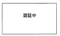
- ATM1 of this embodiment although demonstrated as what makes a customer input a birth date in a Japanese calendar, you may make it input in a Western calendar. In that case, the DB server 4 side may also store the date of birth of the customer in the Christian era. And the control part 10 of ATM1 displays the screen (refer FIG. 14) showing that it is authenticating on the operation display part 31, and also requests
- the application server 2 When receiving the biometric authentication request from the ATM 1, the application server 2 first transfers the date of birth related to the biometric authentication request to the DB server 4 and searches for an account corresponding to the date of birth. A request is made (S106).
- the DB server 4 When receiving the account search request, the DB server 4 detects the account information (including the account number and biometric information identifier) corresponding to the date of birth related to the search request from the account correspondence information storage unit 41. (S107), a response is made to the application server 2 (S108).
- the account information including the account number and biometric information identifier
- the date of birth input reception screen (see FIG. 13 described above) indicated by ATM 1 does not require the input of the era when receiving the date of birth. Therefore, in the application server 2, the date of birth is verified by discarding the era part.
- the contents of the account correspondence information storage unit 41 are the contents shown in FIG. Since the date of birth input by the customer is “January 10, 2010”, the DB server 4 uses the account number “0000001” and the biometric identifier “10001” as a candidate for the customer's account. Then, the account with the account number “0000004” and the biometric information identifier “10004” is detected. Then, the DB server 4 returns the information of these two accounts (including at least the account number and the biometric information identifier) to the application server 2. As described above, in the transaction system 1000, the process of searching for (squeezing) candidates for the account of the customer currently using ATM1 is performed using the date of birth as a key.
- the application server 2 respond
- the biometric information identifier (the biometric information identifier included in the search result of the DB server 4) is transmitted to the authentication server 5 (S109).
- the authentication server 5 When the authentication server 5 receives the authentication processing request, the authentication server 5 detects the biometric information corresponding to the biometric information identifier included in the supplied authentication request from the registered authentication information storage unit 51 and compares it with the supplied biometric information. Authentication processing (collation processing) is performed (S110), and the authentication result is returned to the application server 2 (S111). As described above, here, “10001” and “10004” are transmitted from the application server 2 to the authentication server 5 as biometric information identifiers corresponding to the customer account candidates. Therefore, the authentication server 5 extracts the biometric information BD1 corresponding to the biometric information identifier “10001” and the biometric information BD4 corresponding to the biometric information identifier “10004” from the registered authentication information storage unit 51.
- the authentication server 5 performs the process which tries to detect what corresponds to the said customer's biometric information from the extracted biometric information BD1 and BD4, and determines that the authentication has succeeded only when the match can be detected. Then, the authentication server 5 returns a biometric information identifier “10001” that has been successfully authenticated to the application server 2 as an authentication result, together with the fact that the authentication has been successful.
- the authentication server 5 performs the following description assuming that the biometric information acquired from the customer matches the biometric information BD1. If the authentication server 5 fails to detect the biometric information obtained from the customer, it is determined that the authentication has failed, and the fact is transmitted to the ATM 1 via the application server 2. You may do it. Then, in the case of authentication failure, ATM1 may cancel the cardless transaction with the customer.
- the customer account is identified from the customer account candidates based on the biometric information identifier included in the authentication result. (S112).
- step S110 movement when one customer owns only one account is demonstrated here, one customer may own several accounts.
- a plurality of matching biometric information identifiers are detected in the process of step S110, and a plurality of accounts of the customer are specified in the above-described step S112.
- the application server 2 can specify the account of the customer as the account with the account number “0000001”.
- the application server 2 requests
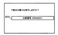
- the control unit 10 of the ATM 1 causes the customer to confirm the account used for the transaction (hereinafter referred to as “account”). (Referred to as “confirmation screen”) is displayed on the operation display unit 31 (S114).
- FIG. 15 is an explanatory diagram showing a configuration example of an account confirmation screen displayed on the screen of the operation display unit 31.
- a button corresponding to each account (account number) is arranged, and the control unit 10 of the ATM 1 determines that the account (account number) corresponding to the pressed button is the customer. Treated as an account confirmed (selected) by.
- FIG. 15 shows, as an example, a state in which a button B501 corresponding to one account (a button displayed as “account number: 0000001”) is arranged.
- a button displayed as “account number: 0000001” a button displayed as “account number: 0000001”
- the button B501 displaying “Account No. 0000001” is pressed on the account selection acceptance screen of FIG. If the customer has a plurality of accounts, buttons corresponding to each of the plurality of accounts are arranged on this screen.
- control unit 10 of the ATM 1 returns a confirmation result by the customer (including the account number confirmed on the account confirmation screen) to the application server 2 (S115).
- control unit 10 of the ATM 1 displays on the operation display unit 31 a screen for requesting the customer to input a password corresponding to the account (hereinafter referred to as “password input acceptance screen”). (S116).
- FIG. 16 is an explanatory diagram showing a configuration example of a screen displayed on the operation display unit 31 by the control unit 10 of the ATM 1 when receiving an input of a personal identification number from a customer.
- a soft keypad K601 for inputting a personal identification number
- a transaction stop button B601 for displaying the number of digits of the personal identification number entered.
- the soft keypad K601 includes “0 to 9” and “OK” buttons (input keys).
- a correction button B602 for correcting an already input number (for example, erasing a part or all of the already input number) is arranged on the password input acceptance screen. .
- the control unit 10 of the ATM 1 starts a customer monitoring process (details will be described later) by the proximity sensor 70 (S117), and further transmits the input personal identification number to the application server 2. Then, an authentication request with a personal identification number is made (S118).
- the application server 2 When the application server 2 receives an authentication request using a personal identification number from the ATM 1, the application server 2 transmits an authentication request (authentication request using the personal identification number) for performing the transaction for the account of the account number used for the current transaction to the host computer 3. (S119).
- the host computer 3 performs authentication processing (collation processing with a personal identification number corresponding to the stored account number) based on the account number and personal identification number included in the authentication request received from the application server 2. . Then, the host computer 3 returns an authentication result to the ATM 1 via the application server 2 (S120). Here, it is assumed that the authentication process (authentication process using a personal identification number) by the host computer 3 is successful.
- the control unit 10 of the ATM 1 makes a transaction process request (request for transaction process for balance inquiry) to the host computer 3 via the application server 2. (S121).
- the host computer 3 that has received the request for transaction processing (balance inquiry) performs transaction processing based on the request, and returns the processing result to the ATM 1 via the application server 2 (S122).
- the transaction processing (balance inquiry transaction processing) by the host computer 3 is successful and the balance of the account is notified to the ATM 1.
- control part 10 of ATM1 displays the screen (henceforth a "balance display screen") for displaying the notified balance of the said account on the operation display part 31 (S123).
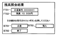
- FIG. 17 is an explanatory diagram showing a configuration example of the balance display screen.
- a field F701 for displaying account information (account number and the like) related to balance inquiry and a field F702 for displaying the balance of the account are arranged.
- a button that can shift from the balance inquiry to another transaction is terminated without shifting to the other transaction.
- Button B703 (a button displaying "END") is arranged.
- buttons B 701 (a button labeled “withdrawal”) that can be transferred to a withdrawal transaction, and a transfer to a deposit transaction.
- a button B702 (a button labeled “deposit”) that can be used is arranged. In this example, it is assumed that the customer presses a button B701 that can shift to a withdrawal transaction on the balance display screen.
- control part 10 of ATM1 transfers to the process of the withdrawal transaction of the said account, and first, the screen (henceforth "withdrawal amount input acceptance screen" with which a customer inputs a withdrawal amount (transaction amount)) and Is displayed on the operation display unit 31 (S124).
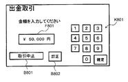
- FIG. 18 shows a configuration example of a screen (hereinafter referred to as “withdrawal amount input acceptance screen”) displayed on the operation display unit 31 by the control unit 10 of the ATM 1 when receiving an input of the withdrawal amount from the customer. It is explanatory drawing.
- a soft keypad K801 for inputting the withdrawal amount a transaction stop button B801, and a field F801 for displaying the entered withdrawal amount are displayed.
- the soft keypad K801 includes “0-9” and “OK” buttons (input keys).
- the withdrawal amount input acceptance screen includes a correction button B802 for correcting the amount already input (for example, erasing part or all of the content input in the field F801). Has been.
- the control unit 10 of the ATM 1 makes a transaction processing request (request for the transaction processing of the withdrawal transaction) to the host computer 3 via the application server 2 (S125).
- the host computer 3 that has received the transaction processing request performs the transaction processing based on the request, and returns the processing result to the ATM 1 via the application server 2 (S126).
- transaction processing withdrawal transaction processing
- control part 10 of ATM1 will discharge
- the transaction process is terminated (S127).
- the control unit 10 of the ATM 1 ends the customer monitoring process (details will be described later) by the proximity sensor 70 (S128), and displays the transaction selection screen. It is displayed on the unit 31 and the next transaction can be accepted (S129).
- the control unit 10 of the ATM 1 performs customer monitoring processing using the proximity sensor 70 between the input of the password and the end of the transaction (between the steps S117 to S128 described above). When it is confirmed that the user has left, the transaction is canceled.
- control unit 10 of the ATM 1 performs the transaction processing in the flowchart of FIG. 9 in parallel with the transaction process from the input of the password to the end of the transaction (between the above-described steps S117 to S128). Process.
- the control unit 10 of the ATM 1 When the customer monitoring process is started, the control unit 10 of the ATM 1 performs a process of detecting the presence or absence of a nearby customer by the proximity sensor 70 (S201), and confirms the detection result (S202). When the control unit 10 of the ATM 1 can confirm (detect) that there is a customer in the vicinity, the control unit 10 returns to the process of step S201 described above, and again detects the presence or absence of the peripheral customer by the proximity sensor 70. Process. Further, when it is confirmed that there is no customer in the vicinity, the control unit 10 of the ATM 1 determines that the customer has left the vicinity of the ATM 1 in the middle of the transaction, and performs a process of canceling the transaction (S203). ).
- control unit 10 of the ATM 1 cancels the transaction process (the process shown in the sequence diagrams of FIGS. 6 to 8) that has been continued until then, and further displays the initial screen (transaction method selection screen) as the operation display unit. 31 to display a state where the next transaction can be accepted.
- FIGS. 19 and 20 are sequence diagrams showing the operation (including the operation of ATM1) in the transaction system 1000 when a transaction with a card is performed.
- FIGS. 19 and 20 show an example in which a withdrawal transaction is continuously performed from the balance inquiry.
- the control unit 10 of the ATM 1 displays a transaction selection screen (see FIG. 11 described above) for allowing the customer to select transaction details. This is displayed on the unit 31.
- the control unit 10 of the ATM 1 prompts the customer to insert a cash card (hereinafter referred to as “card insertion request screen”). Is displayed on the operation display unit 31 (S303).
- FIG. 22 is an explanatory diagram showing a configuration example of a card insertion request screen displayed on the screen of the operation display unit 31.
- a message prompting the customer to insert a cash card (a message “Please insert a cash card” in FIG. 12) and a transaction stop button B901 for accepting a transaction stop are arranged.
- a cash card is inserted into the card reader 40 by a customer, and data (including at least an account number) recorded on the cash card is read.
- the control unit 10 of the ATM 1 asks the customer to input the personal identification number corresponding to the account, and the personal identification number input acceptance screen (see FIG. 16 described above). Is displayed on the operation display unit 31 (S304).
- the control unit 10 of the ATM 1 performs customer monitoring processing based on a time during which the operation display unit 31 is not continuously operated (hereinafter referred to as “no operation time”) ( Details will be described later (S305).
- control unit 10 of the ATM 1 transmits the account number read from the cash card and the input personal identification number to the application server 2 and makes an authentication request using the personal identification number (S306).
- the application server 2 When the application server 2 receives the authentication request using the personal identification number from the ATM 1, the application server 2 transmits an authentication request (authentication request using the personal identification number) for performing the transaction for the account number of the account to the host computer 3 (S307). .
- the host computer 3 performs authentication processing (collation processing with a personal identification number corresponding to the stored account number) based on the account number and personal identification number included in the authentication request received from the application server 2. . Then, the host computer 3 returns an authentication result to the ATM 1 via the application server 2 (S308). Here, it is assumed that the authentication process (authentication process using a personal identification number) by the host computer 3 is successful.
- the control unit 10 of the ATM 1 makes a transaction process request (request for transaction process for balance inquiry) to the host computer 3 via the application server 2. (S309).
- the host computer 3 that has received the transaction processing request performs the transaction processing based on the request, and returns the processing result to the ATM 1 via the application server 2 (S310).
- the transaction processing balance inquiry transaction processing
- control part 10 of ATM1 displays on the operation display part 31 the balance display screen (refer FIG. 17 mentioned above) for displaying the notified balance of the said account (S311).
- the customer presses a button B701 that can shift to a withdrawal transaction on the balance display screen.
- control part 10 of ATM1 transfers to the process of the withdrawal transaction of the said account, and, first, the withdrawal amount input reception screen for making a customer input withdrawal amount (transaction amount) (refer above-mentioned FIG. 18). Is displayed on the operation display unit 31 (S312).
- the control unit 10 of the ATM 1 requests the host computer 3 via the application server 2 for a transaction process (request for the transaction process of the withdrawal transaction). (S313).
- the host computer 3 that has received the transaction processing request performs the transaction processing based on the request, and returns the processing result to the ATM 1 via the application server 2 (S314).
- transaction processing withdrawal transaction processing
- control part 10 of ATM1 will discharge
- the transaction process is terminated (S315).
- the control unit 10 of the ATM 1 finishes the customer monitoring process (details will be described later) based on the no-operation time (S316), displays the transaction selection screen on the operation display unit 31, and The transaction is accepted (S317).
- control unit 10 of the ATM 1 performs the customer monitoring process based on the no-operation time for the ATM 1 until the transaction is ended after the password is input (between the steps S305 to S316 described above), When it is confirmed that the customer has left the vicinity of ATM1, processing for canceling the transaction is performed.
- control unit 10 of the ATM 1 performs the transaction processing in the flowchart of FIG. 21 in parallel with the transaction process from the input of the password to the end of the transaction (between steps S305 to S315 described above). Process.
- control unit 10 of the ATM 1 starts monitoring the no-operation time for the ATM 1 (S401).
- the control unit 10 of the ATM 1 confirms whether or not the no-operation time is less than the timeout time (hereinafter referred to as “no-operation timeout time”) (S402).
- control part 10 of ATM1 confirms that the no-operation time under monitoring is less than the no-operation timeout time
- the control unit 10 of the ATM 1 determines that the customer has left the vicinity of the ATM 1 during the transaction. Then, processing for canceling the transaction is performed (S403).
- the control unit 10 of the ATM 1 stops the transaction process (the process shown in the sequence diagrams of FIGS. 19 to 20) that has been continued until then, and further displays an initial screen (transaction method selection screen) as an operation display unit. 31 to display a state where the next transaction can be accepted.
- the “no-operation time” means, for example, that the ATM 1 makes a request for any operation (for example, information input, card insertion, cash-in operation, etc.) to the customer after the customer makes a request for a predetermined time.
- the time when no operation is performed shall be called.
- you may make it time-measure the non-operation time as follows, for example. For example, in the case of a personal identification number input screen, the control unit 10 of the ATM 1 starts to display the screen and then starts measuring the no-operation time, and any operation key (button) for the operation display unit 31 is pressed. Repeat the process of initializing the no-operation time during time counting (initializing the time during time counting to 0).
- control unit 10 of the ATM 1 measures the non-operation time every time the screen switching of the operation display unit 31 occurs.
- the control unit 10 of the ATM 1 performs a process of monitoring whether or not the no-operation time exceeds the no-operation timeout time by counting the no-operation time by the process as described above, for example.
- the length of the no-operation timeout applied in transactions with cards is not limited, but may be, for example, about 60 seconds.
- ATM1 while performing a cardless transaction with a customer, a customer monitoring process using the proximity sensor 70 is performed, and if the customer cannot be detected by the proximity sensor 70, a process for canceling the transaction is performed. Yes.
- security of transaction can be improved, respond
- the system of the customer monitoring (detection) performed by a customer monitoring process is switched according to a transaction system (cardless transaction or transaction with a card
- the customer is monitored based on the detection status of the proximity sensor 70 in the case of a cardless transaction, and the customer is monitored based on the no-operation time in the case of a transaction with a card.
- ATM 1 of the first embodiment it is possible to shift from balance inquiry to other transactions (withdrawal transactions) and perform continuous transactions. And in ATM1 of 1st Embodiment, when a continuous transaction is performed, the input of authentication information (a PIN number, biometric information, etc.) is requested
- authentication information a PIN number, biometric information, etc.
- the ATM 1 of the second embodiment when continuous transactions are performed by cardless transaction, it is configured to request input of re-authentication information for performing re-authentication for each transaction.
- the re-authentication information includes some or all items of information (birth date, biometric information, and personal identification number) used in the first authentication.
- the ATM 1 of the second embodiment for example, it is assumed that the user is requested to input a personal identification number as re-authentication information.
- the control unit 10 of the ATM 1 of the second embodiment repeats the password between the balance display screen in step S123 and the withdrawal amount input acceptance screen in step S124. It is also possible to perform processing for displaying a personal identification number input acceptance screen (same screen as in FIG. 16 described above) for requesting the input of. And the control part 10 of ATM1 of 2nd Embodiment hold
- the control unit 10 of the ATM 1 may request the external system to perform the authentication process for the re-authentication process, but the load on the external system can be reduced by completing the re-authentication process inside the ATM 1. In addition, the processing time of the re-authentication process can be shortened.
- the second and subsequent transactions are requested for re-authentication information (customer input in the first authentication process).
- the user is requested to input authentication information (part or all of the authentication information), and re-authentication processing (collation processing with the authentication information input to the customer in the first authentication processing) is performed.
- the operation screen structure for example, the operation screen structure which can transfer to a withdrawal transaction from a balance inquiry display screen
- impersonation by a third party can be suppressed.
- ATM1 even if the customer leaves the ATM1 while the balance inquiry display screen is displayed, and the proximity sensor 70 cannot detect that the customer has left, impersonation by a third party is suppressed. can do.
- the customer monitoring process is performed using the proximity sensor 70.
- the proximity sensor 70 cannot be used (for example, when the proximity sensor 70 fails)
- the customer monitoring process is performed by another method. Processing may be performed.
- the method for determining whether or not the proximity sensor 70 can be used is not limited. For example, the determination may be made by a self-diagnosis function at startup or a hardware monitoring function after startup. .
- the structure similar to the existing ATM is applicable, for example.
- the customer monitoring process is performed using no operation time for cardless transactions.
- the no-operation timeout time (henceforth "the 2nd no-operation timeout time") used by cardless transaction is the timeout time (henceforth a card-less transaction). , Also referred to as “first no-operation timeout time”).
- curd shall be 60 second
- the 2nd no-operation timeout time set by cardless transaction shall be 30 second. Also good.
- ATM1 of 3rd Embodiment when a no-operation time becomes more than a 2nd no-operation timeout time by the customer monitoring process of a cardless transaction, a transaction is once interrupted without stopping a transaction immediately.
- the re-authentication information input request and re-authentication processing are performed.
- a part of the information (birth date, biometric information, and password) used in the first authentication or All items need only be included.
- ATM1 of 3rd Embodiment demonstrates as what requests
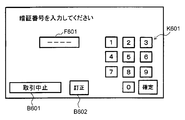
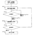
- the control part 10 of ATM1 of 3rd Embodiment will start the monitoring of the no-operation time with respect to the said ATM1, if a customer monitoring process is started at the time of a cardless transaction (S501).
- control part 10 of ATM1 confirms whether a no-operation time is less than 2nd timeout time (time shorter than 1st no-operation timeout time) (S502).
- the control unit 10 of the ATM 1 confirms that the non-operation time being monitored is less than the second non-operation time-out time, the customer is regarded as continuing the transaction, and the non-operation time is determined in step S501. Continue monitoring.
- the control unit 10 of the ATM 1 makes an input request for re-authentication information (S503).
- the date of birth is applied as the re-authentication information
- the control unit 10 of the ATM 1 displays the date of birth input acceptance screen (see FIG. 13 above) and accepts the date of birth from the customer.
- biometric information is applied as re-authentication information
- the control unit 10 of the ATM 1 displays a biometric information input acceptance screen (see FIG. 11 described above) and accepts input of biometric information from the customer. It may be.
- control part 10 of ATM1 performs a re-authentication process, and determines a subsequent process according to the authentication result (S504).
- the control unit 10 of the ATM 1 performs re-authentication processing using the re-authentication information. If the authentication is successful, the screen returns to the screen before requesting the input of re-authentication information, and the non-operation time is continuously monitored in step S501.
- the control unit 10 of the ATM 1 determines that the customer has left the ATM 1. Then, transaction cancellation processing (S505) is performed.
- control unit 10 of the ATM 1 holds the authentication information input in the first authentication process, and collates with the held authentication information in the re-authentication process.
- control unit 10 of the ATM 1 of the third embodiment may request an external system for the authentication process.
- the proximity sensor 70 cannot be used, whether or not the customer has left the ATM 1 using the no-operation time or the re-authentication process.
- Monitoring customer monitoring processing
- the present invention may be applied to other transaction apparatuses.
- the present invention can be applied to a system for performing a transaction in which electronic money or the like is charged (deposited) into a customer's account or a transaction in which electronic money is withdrawn from the customer's account and a product (for example, a ticket for transportation, etc.) is sold. .
- the ATM in each of the above embodiments supports both cardless transactions and transactions using cash cards, but may be constructed as an ATM that supports only cardless transactions.
- the customer's date of birth is used to extract a candidate for the customer's account. You may make it extract the candidate of the said customer's account using information.
- the candidate of the customer's account is extracted by using an individual identifier (hereinafter referred to as "individual ID") assigned to each account, instead of the date of birth, or an account number situation. You may do it.
- This individual ID is an identifier different from the account number allocated for each account.
- the individual ID may be any content that is easy for a customer to remember, but the individual ID is preferably unique for each account.
- it is desirable that the individual ID has a format that is easier for the customer to remember than the account number itself, such as a digit less than the account number.
Landscapes
- Business, Economics & Management (AREA)
- Accounting & Taxation (AREA)
- Finance (AREA)
- Physics & Mathematics (AREA)
- General Physics & Mathematics (AREA)
- Strategic Management (AREA)
- General Business, Economics & Management (AREA)
- Engineering & Computer Science (AREA)
- Theoretical Computer Science (AREA)
- Financial Or Insurance-Related Operations Such As Payment And Settlement (AREA)
Priority Applications (1)
| Application Number | Priority Date | Filing Date | Title |
|---|---|---|---|
| CN201380030134.1A CN104380353B (zh) | 2012-06-25 | 2013-05-10 | 交易装置以及存储程序的存储介质 |
Applications Claiming Priority (2)
| Application Number | Priority Date | Filing Date | Title |
|---|---|---|---|
| JP2012-142167 | 2012-06-25 | ||
| JP2012142167A JP5970974B2 (ja) | 2012-06-25 | 2012-06-25 | 取引装置及びプログラム |
Publications (1)
| Publication Number | Publication Date |
|---|---|
| WO2014002621A1 true WO2014002621A1 (ja) | 2014-01-03 |
Family
ID=49782795
Family Applications (1)
| Application Number | Title | Priority Date | Filing Date |
|---|---|---|---|
| PCT/JP2013/063191 Ceased WO2014002621A1 (ja) | 2012-06-25 | 2013-05-10 | 取引装置及びプログラムを格納する記憶媒体 |
Country Status (3)
| Country | Link |
|---|---|
| JP (1) | JP5970974B2 (enExample) |
| CN (1) | CN104380353B (enExample) |
| WO (1) | WO2014002621A1 (enExample) |
Cited By (1)
| Publication number | Priority date | Publication date | Assignee | Title |
|---|---|---|---|---|
| JP7429819B1 (ja) | 2023-04-05 | 2024-02-08 | 株式会社セブン銀行 | 取引システム、取引装置、取引方法、およびプログラム |
Families Citing this family (6)
| Publication number | Priority date | Publication date | Assignee | Title |
|---|---|---|---|---|
| JP6341031B2 (ja) | 2014-09-22 | 2018-06-13 | 富士通株式会社 | アクセス制御プログラム、アクセス制御方法及び情報処理装置 |
| JP6471477B2 (ja) * | 2014-11-28 | 2019-02-20 | 沖電気工業株式会社 | 現金処理機 |
| JPWO2017051917A1 (ja) * | 2015-09-25 | 2018-07-12 | 日本電産サンキョー株式会社 | カードリーダ |
| JP6790588B2 (ja) * | 2016-08-26 | 2020-11-25 | 沖電気工業株式会社 | 自動取引装置、自動取引システム及び自動取引プログラム |
| JP7297698B2 (ja) * | 2020-01-31 | 2023-06-26 | 日立チャネルソリューションズ株式会社 | 端末管理システム、端末管理装置及びその方法 |
| JP7577035B2 (ja) * | 2021-07-15 | 2024-11-01 | 日立チャネルソリューションズ株式会社 | 現金自動取引システム |
Citations (5)
| Publication number | Priority date | Publication date | Assignee | Title |
|---|---|---|---|---|
| JPH07334588A (ja) * | 1994-06-07 | 1995-12-22 | Oki Electric Ind Co Ltd | 自動取引装置 |
| JP2009070199A (ja) * | 2007-09-14 | 2009-04-02 | Oki Electric Ind Co Ltd | 自動取引装置 |
| JP2010049387A (ja) * | 2008-08-20 | 2010-03-04 | Oki Electric Ind Co Ltd | 自動取引システム、サービス管理サーバ、自動取引装置および自動取引方法 |
| JP2010152506A (ja) * | 2008-12-24 | 2010-07-08 | Hitachi Omron Terminal Solutions Corp | 利用者認証端末、認証システム、利用者認証方法、および利用者認証プログラム |
| JP2012008758A (ja) * | 2010-06-24 | 2012-01-12 | Hitachi Omron Terminal Solutions Corp | 取引処理装置及び取引処理方法 |
Family Cites Families (5)
| Publication number | Priority date | Publication date | Assignee | Title |
|---|---|---|---|---|
| JP2007323517A (ja) * | 2006-06-02 | 2007-12-13 | Oki Electric Ind Co Ltd | 自動取引装置 |
| JP5050540B2 (ja) * | 2007-01-29 | 2012-10-17 | 沖電気工業株式会社 | 紙葉類処理装置 |
| JP5227070B2 (ja) * | 2008-04-22 | 2013-07-03 | 日立オムロンターミナルソリューションズ株式会社 | 現金自動取引装置 |
| JP4931860B2 (ja) * | 2008-06-02 | 2012-05-16 | 日立オムロンターミナルソリューションズ株式会社 | 自動処理装置 |
| CN101556719A (zh) * | 2009-05-21 | 2009-10-14 | 中国建设银行股份有限公司 | 自助终端处理交易的方法和自助终端 |
-
2012
- 2012-06-25 JP JP2012142167A patent/JP5970974B2/ja active Active
-
2013
- 2013-05-10 CN CN201380030134.1A patent/CN104380353B/zh not_active Expired - Fee Related
- 2013-05-10 WO PCT/JP2013/063191 patent/WO2014002621A1/ja not_active Ceased
Patent Citations (5)
| Publication number | Priority date | Publication date | Assignee | Title |
|---|---|---|---|---|
| JPH07334588A (ja) * | 1994-06-07 | 1995-12-22 | Oki Electric Ind Co Ltd | 自動取引装置 |
| JP2009070199A (ja) * | 2007-09-14 | 2009-04-02 | Oki Electric Ind Co Ltd | 自動取引装置 |
| JP2010049387A (ja) * | 2008-08-20 | 2010-03-04 | Oki Electric Ind Co Ltd | 自動取引システム、サービス管理サーバ、自動取引装置および自動取引方法 |
| JP2010152506A (ja) * | 2008-12-24 | 2010-07-08 | Hitachi Omron Terminal Solutions Corp | 利用者認証端末、認証システム、利用者認証方法、および利用者認証プログラム |
| JP2012008758A (ja) * | 2010-06-24 | 2012-01-12 | Hitachi Omron Terminal Solutions Corp | 取引処理装置及び取引処理方法 |
Cited By (2)
| Publication number | Priority date | Publication date | Assignee | Title |
|---|---|---|---|---|
| JP7429819B1 (ja) | 2023-04-05 | 2024-02-08 | 株式会社セブン銀行 | 取引システム、取引装置、取引方法、およびプログラム |
| JP2024149337A (ja) * | 2023-04-05 | 2024-10-18 | 株式会社セブン銀行 | 取引システム、取引装置、取引方法、およびプログラム |
Also Published As
| Publication number | Publication date |
|---|---|
| CN104380353A (zh) | 2015-02-25 |
| JP5970974B2 (ja) | 2016-08-17 |
| JP2014006718A (ja) | 2014-01-16 |
| CN104380353B (zh) | 2018-01-16 |
Similar Documents
| Publication | Publication Date | Title |
|---|---|---|
| JP5970974B2 (ja) | 取引装置及びプログラム | |
| JP5084712B2 (ja) | 利用者認証端末、認証システム、利用者認証方法、および利用者認証プログラム | |
| US8910861B2 (en) | Automatic teller machine (“ATM”) including a user-accessible USB port | |
| US20130265136A1 (en) | Dynamic keypad and fingerprinting sequence authentication | |
| EP3254218B1 (en) | Secure data entry device | |
| JP2005038257A (ja) | 情報処理システム、本人認証装置、生体特徴情報更新方法およびプログラム | |
| TWI332637B (en) | Biometrics system and method thereof | |
| CN100578558C (zh) | 交易处理系统 | |
| JP2007102278A (ja) | 自動取引装置 | |
| JP2006178709A (ja) | 現金自動取引装置 | |
| JP6078985B2 (ja) | 取引装置 | |
| KR20090022682A (ko) | 키스트로크 기반 행동 패턴 정보를 이용한 금융 거래서비스 제공 방법 및 시스템 | |
| JP4109291B2 (ja) | 自動取引装置 | |
| JP2012247970A (ja) | 取引処理装置、及び取引処理方法 | |
| JP2011123729A (ja) | 認証システム、人体通信端末装置、およびホスト装置 | |
| JP2010129012A (ja) | カード処理装置、方法およびプログラム | |
| JP2008010017A (ja) | 自動取引システム | |
| JP6064385B2 (ja) | 取引装置 | |
| JP4800131B2 (ja) | 生体認証装置とそのシステム、および取引処理装置 | |
| JP2007280405A (ja) | 本人認証方法 | |
| JP6455069B2 (ja) | 取引装置及び取引システム | |
| JP2007179303A (ja) | 自動取引システム、装置、及び、方法 | |
| JP2008198089A (ja) | 現金自動取引システム | |
| JP5708353B2 (ja) | 入力装置及び照合システム | |
| US20220398901A1 (en) | Biometric Automated Teller Machine |
Legal Events
| Date | Code | Title | Description |
|---|---|---|---|
| 121 | Ep: the epo has been informed by wipo that ep was designated in this application |
Ref document number: 13808612 Country of ref document: EP Kind code of ref document: A1 |
|
| NENP | Non-entry into the national phase |
Ref country code: DE |
|
| 122 | Ep: pct application non-entry in european phase |
Ref document number: 13808612 Country of ref document: EP Kind code of ref document: A1 |