WO2013190932A1 - ドア - Google Patents
ドア Download PDFInfo
- Publication number
- WO2013190932A1 WO2013190932A1 PCT/JP2013/063555 JP2013063555W WO2013190932A1 WO 2013190932 A1 WO2013190932 A1 WO 2013190932A1 JP 2013063555 W JP2013063555 W JP 2013063555W WO 2013190932 A1 WO2013190932 A1 WO 2013190932A1
- Authority
- WO
- WIPO (PCT)
- Prior art keywords
- door
- baffle
- auxiliary
- vent
- hollow portion
- Prior art date
- Legal status (The legal status is an assumption and is not a legal conclusion. Google has not performed a legal analysis and makes no representation as to the accuracy of the status listed.)
- Ceased
Links
Images





















Classifications
-
- E—FIXED CONSTRUCTIONS
- E06—DOORS, WINDOWS, SHUTTERS, OR ROLLER BLINDS IN GENERAL; LADDERS
- E06B—FIXED OR MOVABLE CLOSURES FOR OPENINGS IN BUILDINGS, VEHICLES, FENCES OR LIKE ENCLOSURES IN GENERAL, e.g. DOORS, WINDOWS, BLINDS, GATES
- E06B3/00—Window sashes, door leaves, or like elements for closing wall or like openings; Layout of fixed or moving closures, e.g. windows in wall or like openings; Features of rigidly-mounted outer frames relating to the mounting of wing frames
- E06B3/70—Door leaves
- E06B3/82—Flush doors, i.e. with completely flat surface
- E06B3/822—Flush doors, i.e. with completely flat surface with an internal foursided frame
-
- E—FIXED CONSTRUCTIONS
- E06—DOORS, WINDOWS, SHUTTERS, OR ROLLER BLINDS IN GENERAL; LADDERS
- E06B—FIXED OR MOVABLE CLOSURES FOR OPENINGS IN BUILDINGS, VEHICLES, FENCES OR LIKE ENCLOSURES IN GENERAL, e.g. DOORS, WINDOWS, BLINDS, GATES
- E06B7/00—Special arrangements or measures in connection with doors or windows
- E06B7/02—Special arrangements or measures in connection with doors or windows for providing ventilation, e.g. through double windows; Arrangement of ventilation roses
-
- E—FIXED CONSTRUCTIONS
- E06—DOORS, WINDOWS, SHUTTERS, OR ROLLER BLINDS IN GENERAL; LADDERS
- E06B—FIXED OR MOVABLE CLOSURES FOR OPENINGS IN BUILDINGS, VEHICLES, FENCES OR LIKE ENCLOSURES IN GENERAL, e.g. DOORS, WINDOWS, BLINDS, GATES
- E06B3/00—Window sashes, door leaves, or like elements for closing wall or like openings; Layout of fixed or moving closures, e.g. windows in wall or like openings; Features of rigidly-mounted outer frames relating to the mounting of wing frames
- E06B3/70—Door leaves
- E06B2003/7094—Door leaves with ventilated innerspace
-
- E—FIXED CONSTRUCTIONS
- E06—DOORS, WINDOWS, SHUTTERS, OR ROLLER BLINDS IN GENERAL; LADDERS
- E06B—FIXED OR MOVABLE CLOSURES FOR OPENINGS IN BUILDINGS, VEHICLES, FENCES OR LIKE ENCLOSURES IN GENERAL, e.g. DOORS, WINDOWS, BLINDS, GATES
- E06B5/00—Doors, windows, or like closures for special purposes; Border constructions therefor
- E06B5/20—Doors, windows, or like closures for special purposes; Border constructions therefor for insulation against noise
- E06B5/205—Doors, windows, or like closures for special purposes; Border constructions therefor for insulation against noise windows therefor
Definitions
- the present invention relates to a door provided at an entrance of a toilet room or a living room, and particularly relates to a door provided with a hollow portion for ventilation and a vent.
- Patent Documents 1 and 2 describe doors in which the interior of the door is a hollow portion and ventilating functions are provided by providing vents on the front and back surfaces of the door, respectively.
- one of the front-side and back-side vents is provided in the upper part of the door, and the other is provided in the lower part of the door, so that the hollow part extends vertically. Further, a sound absorbing material is lined in the hollow portion to provide a soundproofing function.
- FIG. 3 of Patent Document 1 describes that one of the vents is provided along one side of the door and the other vent is provided along the other side.
- the object of the present invention is to provide a door excellent in ventilation function and soundproofing function.
- Patent Documents 1 and 2 the inside of the door is a hollow portion, and the face material is not lined with the door frame in the vicinity of the vent, so the strength and rigidity of the face material in the vicinity of the vent are There are shortcomings such as shortage of face materials and easy vibration.
- an object of the present invention is to provide a door having high strength and rigidity of a face material in the vicinity of the vent.
- a hollow portion is provided inside the door, and a vent hole communicating with the hollow portion is provided on one side and the other side of the door, respectively.
- the hollow portion in the vicinity of the first vent connects the first and second vents.
- the first narrow portion having a small width in the crossing direction and the hollow portion in the vicinity of the second vent is a second narrow portion having a small width in the crossing direction
- a portion between the first small width portion and the second small width portion is a large width portion having a width in the intersecting direction larger than that of the first and second small width portions.
- the vent may extend along one side of the door.
- face members are provided on both sides of the door frame surrounding the hollow portion, and the vent holes are provided in the face members, respectively.
- It has a crosspiece and a horizontal crosspiece, and a plurality of auxiliary crosspieces along the vertical crosspiece or the horizontal crosspiece, the auxiliary crosspieces are arranged at intervals, and the narrow portion is formed between the auxiliary crosspieces. It may be.
- a portion in the vicinity of the vent is coupled to the supplementary bar.
- a baffle for reducing the width of the hollow portion in the intersecting direction may be provided at a position between the first vent hole and the second vent hole.
- a plurality of the baffles are arranged at intervals in the crossing direction.
- the baffle may have a V-shape or a plate having three or more leaves extending in the radial direction.
- the hollow portion is a narrow portion in the vicinity of the vent, and the space between the narrow portions is a large portion, and when the sound wave enters the wide portion from the small portion.
- the silencing action is achieved by the rapid expansion of the cross-sectional area of the hollow portion.
- the strength and rigidity of the face material in the vicinity of the vent hole are increased by connecting and supporting the vicinity of the vent hole to the auxiliary frame of the door frame.
- FIG. 5 is an enlarged sectional view taken along line VV in FIG. 4.
- FIG. 6 is an enlarged sectional view taken along line VI-VI in FIG. 4.
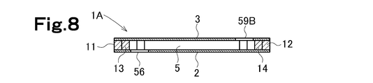
- FIG. 8 is a sectional view taken along line VIII-VIII in FIG. 7. It is the perspective view which abbreviate
- FIG. 21a is a front view in which the face material on the front side of the door according to the embodiment is omitted
- FIG. 21b is an enlarged view of the XXIB portion of FIG. 21a.
- FIG. 21b is a front view of the door which concerns on embodiment. It is the perspective view which abbreviate
- FIG. 40a is a perspective view of the front side of a door according to another embodiment
- FIG. 40b is a sectional view taken along line 40B-40B in FIG. 40a.
- 42a to 42d are dimension diagrams of the test bodies 1 and 2.
- FIG. 43a is a longitudinal sectional view of the test apparatus 100, and is a sectional view taken along line 43A-43A of FIG. 43b.
- 43b is a view taken in the direction of arrow 43B-43B in FIG. 43a.
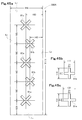
- FIG. 44a is a front view in which the face material on the front side of the door according to the experimental example is omitted
- FIG. 44b is a dimensional diagram of the baffle in FIG. 44a
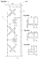
- FIG. 45a is a front view in which the face material and door frame on the front side of the door according to the experimental example are omitted
- FIGS. 45b and 45c are dimensional views of the baffle in FIG. 45a, respectively
- 46a is a front view in which the face material and door frame on the front side of the door according to the experimental example are omitted
- FIGS. 46b to 46d are dimensional views of the baffle in FIG. 46a, respectively.
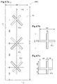
- FIG. 47a is a front view in which the face material and door frame on the front side of the door according to the experimental example are omitted, and FIGS. 47b and 47c are dimensional views of the baffle in FIG. 47a, respectively.
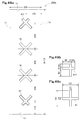
- 48a is a front view in which the face material and door frame on the front side of the door according to the experimental example are omitted, and FIGS. 48b and 48c are dimensional views of the baffle in FIG. 48a, respectively.
- FIG. 49a is a front view in which the face material and door frame on the front side of the door according to the experimental example are omitted, and FIGS. 49b and 49c are dimensional views of the baffle in FIG. 49a, respectively.
- FIG. 49a is a front view in which the face material and door frame on the front side of the door according to the experimental example are omitted, and FIGS. 49b and 49c are dimensional views of the baffle in FIG. 49a, respectively.
- FIG. 50a is a front view in which the face material and door frame on the front side of the door according to the experimental example are omitted
- FIGS. 50b and 50c are dimensional views of the baffle in FIG. 50a, respectively.
- FIG. 51a is a front view in which the face material and door frame on the front side of the door according to the experimental example are omitted
- FIG. 51b is a dimensional view of the baffle in FIG. 51a.
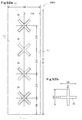
- Fig. 52a is a front view in which the face material and door frame on the front side of the door according to the experimental example are omitted
- Fig. 52b is a dimensional diagram of the baffle in Fig. 52a.
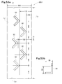
- 53a is a front view in which the face material and door frame on the front side of the door according to the experimental example are omitted
- FIG. 53b is a dimensional view of the baffle in FIG. 53a.
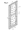
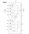
- the door 1 in FIGS. 1 to 6 has a front side member 2 attached to one side of a door frame 10 and a rear side member 3 attached to the other side.
- the door frame 10 has a rectangular frame shape, a pair of first vertical bars 11 and 12 along the vertical side of the door 1, and a second along the inner side of the first vertical bars 11 and 12.
- a crosspiece 24 and a fifth horizontal crosspiece 25 are provided.
- the upper ends of the left vertical rails 11 and 13 and the right vertical rails 12 and 14 are connected by a horizontal beam 21, and the lower ends are connected by horizontal beams 23, 24 and 25.
- ⁇ Short auxiliary bars 31 to 39 are attached to the side surface of the vertical beam 13 on the inner side of the door with a vertical interval.
- Short auxiliary bars 41, 42, and 43 are attached to the side surface of the vertical beam 14 inside the door at intervals in the vertical direction.
- two each of the auxiliary bars 31 to 39 are aligned and attached to the vertical beam 13, and two of the auxiliary bars 41 to 43 are also aligned and attached to the vertical beam 14. .
- the horizontal beam 22 is installed between the auxiliary beam 35 and the auxiliary beam 42.
- the upper end surfaces of the uppermost auxiliary rails 31 and 41 are in contact with the lower surface of the horizontal rail 21.
- the lower end surfaces of the lowermost auxiliary bars 39 and 43 are in contact with the upper surface of the horizontal bar 23.
- the contact portions or overlapping portions of the vertical bars 11 to 14, the horizontal bars 21 to 25, the auxiliary bars 31 to 39, and 41 to 43 are connected by connecting means such as tucker, nails, screws, and adhesives.
- the connecting means may be welding.
- the vertical beam, the horizontal beam, and the auxiliary beam may be cut out from one plate material, or resin, metal, etc. may be integrally molded and cast.
- Ventilation holes 50 to 57 are provided in the face material 2 on the front side.
- the vent 50 is located between the auxiliary bars 31 and 32.
- the vent holes 51 to 57 are provided between the auxiliary bars 32 and 33, between the auxiliary bars 33 and 34, between the auxiliary bars 34 and 35, and the auxiliary bar 35.
- the vertical dimension of the vent 50 matches the vertical dimension between the auxiliary bars 31 and 32.
- the vertical dimension of the vent holes 51 to 57 is between the auxiliary bars 32 and 33, between the auxiliary bars 33 and 34, and the auxiliary bar 34. , 35, between the auxiliary bars 35, 36, between the auxiliary bars 36, 37, between the auxiliary bars 37, 38, and between the auxiliary bars 38, 39.
- the upper edge of the vent 50 matches the lower edge of the auxiliary rail 31, and the upper edges of the vent holes 51 to 57 also match the lower edge of the auxiliary rails 32-38.
- the lower edge of the vent 50 is coincident with the upper edge of the auxiliary bar 32, and the lower edges of the vent holes 51 to 57 are also coincident with the upper edge of the auxiliary bar 33 to 39.
- the left and right widths of the vent holes 50 to 57 are narrower than the width of the two auxiliary bars 31.
- the side of the vents 50 to 57 on the door side coincides with the side of the vertical rail 13 on the door center side.
- the vertical dimensions of the vent holes 58 and 59 are the same as the vertical dimensions between the auxiliary bars 41 and 42 and between the auxiliary bars 42 and 43, respectively.
- the upper edges of the vent holes 58 and 59 coincide with the lower edges of the auxiliary bars 41 and 42.
- the lower edges of the vents 58 and 59 coincide with the upper edges of the auxiliary bars 42 and 43.
- the left and right widths of the vent holes 58 and 59 are narrower than the widths of the two auxiliary bars 41, 42, and 43.
- the sides of the vents 58 and 59 on the door side coincide with the side of the vertical rail 14 on the door center side.
- the face materials 2 and 3 are attached to the door frame 10 by adhering means such as adhesion and screwing.
- the hollow portion 4 or 5 (FIG. 2) surrounded by the face materials 2 and 3 and the door frame 10, the front side vent holes 50 to 57, and the rear side vent hole 58. 59, the front side and the back side of the door 1 communicate with each other and ventilation is performed.
- the vent holes 50 to 57 and the vent holes 58 and 59 are provided in a vertical line along the door side, and the distance from the vent holes 50 to 57 to the vent holes 58 and 59 is short. Therefore, the ventilation resistance which passes the hollow parts 4 and 5 is small, and ventilation performance is favorable.
- auxiliary bars 31, 32 between the auxiliary bars 32, 33, between the auxiliary bars 33, 34, between the auxiliary bars 34, 35, between the auxiliary bars 35, 36, between the auxiliary bars 37, 38, the auxiliary bar 38 and 39 while it has a width small portion of the width dimension d 1.
- 22 of the hollow portion 4 has a width most width dimension d 2
- between the rungs 22 and 23 of the hollow portion 5 becomes the width most width dimension d 3. Therefore, the sound wave that enters the hollow portion 4 or 5 from the vents 50 to 57 has a sudden increase in cross-sectional area when entering from the small width portion of the width dimension d 1 to the large width portion of the width dimension d 2 or d 3. The sound is muted.
- the upper and lower width subsection between Ho ⁇ 41 dimension d 4 is smaller than the vertical dimension d 2 of the width voluminous hollow portion 4, the vertical dimension d 5 is hollow width subsection between Ho ⁇ 43 since part smaller than the vertical dimension d 3 of the width voluminous 5, muffling of the sound waves entering through the ventilation openings 58, 59 into the hollow portion 4, 5 is carried out.
- the face member 2 in the vicinity of the vent holes 50 to 59 is provided.
- 3 has high strength and rigidity. Therefore, damage to the face materials 2 and 3 is prevented and vibration of the face materials 2 and 3 is also suppressed.
- the outer peripheries of the four sides of the door 1 are each in a straight line, and since there are no notches or the like, the gap generated between the door frame when the door is closed is small, Sound is prevented from leaking through the gap. Further, no object is caught in the notch-shaped part.
- the number of vents on the front and back sides of the door may be other than that shown in FIG.
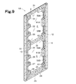
- the door 1A shown in FIGS. 7 to 9 has six front vents and four rear vents.
- Supplementary bars 32, 33, 36, and 37 are disposed between the front-side vent holes 50 and 51, between the vent holes 51 and 52, between the vent holes 54 and 55, and between the vent holes 55 and 56, respectively.
- vents 58A and 58B communicating with the upper hollow part 4 and vent holes 59A and 59B communicating with the lower hollow part 5 are provided.
- a supplementary bar 41A is disposed between the vent holes 58A and 58B, and a supplementary bar 41B is disposed between the vent holes 59A and 59B.
- the other structure of the door 1A is the same as that of the door 1, and the same reference numerals indicate the same parts.
- This door 1A has the same effect as the door 1.
- the supplementary bar 41A is disposed between the vent holes 58A and 58B, and the supplementary bar 41B is disposed between the vent holes 59A and 59B, and the strength and rigidity of the door 1A are improved by the supplementary bar.
- illustration is omitted, the number of front side vents and back side vents may be other than the doors 1 and 1A.
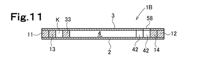
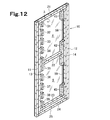
- a door 1B shown in FIGS. 10 to 12 is provided with one auxiliary beam 31 to 34 and 36 to 39 in the door 1, and each auxiliary beam 31 to 34 and 36 to 39 is separated from the vertical beam 13. It is arranged along the vertical rail. Accordingly, a series of long space portions K (FIG. 11) extend vertically between the vertical beam 13 and the auxiliary beams 31 to 34 and between the vertical beam 13 and the auxiliary beams 36 to 39. Yes.
- the auxiliary bars 31 to 34 and 36 to 39 are separated from the vertical bar 13, but the auxiliary bars 31 and 39 are in contact with the vertical bar 13 and only the auxiliary bars 32 to 34 and 36 to 38 are vertical. It may be separated from the crosspiece 13.
- the other structure of the door 1B is the same as that of the door 1, and the same reference numerals indicate the same parts.
- the length in the door width direction of the auxiliary rails 31 to 33, 35 to 37, 39 arranged on both sides of the front side vents 50 to 52, 54 to 56 is the above-mentioned doors. It is larger than 1, 1A and 1B auxiliary bars.
- the vent holes 50 to 52 and 54 to 56 are arranged on the distal end side of the auxiliary rails 31 to 33, 35 to 37, 39, that is, on the hollow portion 4 or 5 side.
- cavities 61 to 66 are formed on the door side side (vertical rail 13 side) from the vent holes 50 to 52 and 54 to 56.
- the hollow portions 61 to 66 are surrounded on three sides by a pair of auxiliary bars and the vertical bars 13, and the other one is open toward the hollow part 4 or 5.
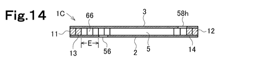
- the depth E of the cavities 61 to 66 that is, the distance E from the edge of the vents 50 to 52, 54 to 56 on the door side side to the innermost part (vertical beam 13) of the cavities 61 to 66 is ⁇ / 4. By doing so, it is possible to efficiently mute the sound having the wavelength ⁇ .
- vents 50 to 52 and four back side vents 58a to 58d are provided in the upper hollow part 4, and three front side holes are provided in the lower hollow part 5.
- Ventilation holes 54 to 56 and four back side ventilation holes 58e to 58h are provided.
- Supplementary bars 41a to 41c are arranged between the vents 58a and 58b, between the vents 58b and 58c, and between the vents 58c and 58d, respectively, between the vents 58e and 58f, between the vents 58f and 58g, and between the vents 58g and 58h.
- the auxiliary bars 41d to 41f are respectively disposed between them.
- the number of vents is not limited to this.
- the other configuration of the door 1C is the same as that of the door 1, and the same reference numerals indicate the same parts.
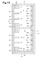
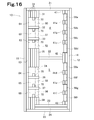
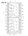
- FIGS. 16 to 21 show doors 1D to 1G, 1G ′, and 1H having different structures each having a hollow portion, and show a front view in a state in which the face material on the front side is removed.
- the door 1D in FIG. 16 includes a protrusion 70 that protrudes from the auxiliary bar into the cavity.
- Each protrusion 70 is provided so as to narrow the width in the vertical direction on the inlet side of the cavities 61 to 66.
- the projections 70 project downward from the auxiliary bars 31 to 33 above the cavities 61 to 63.
- the projections 70 project upward from the auxiliary bars 36, 37, and 39 below the cavities 64 to 66.
- the other structure of the door 1D is the same as that of the door 1C, and the same reference numerals indicate the same parts.
- the door 1E in FIG. 17 is provided with a hollow portion 61a between the auxiliary rail 31 and the horizontal rail 21, and with a hollow portion 63a between the auxiliary rail 34 and the horizontal rail 22, and between the auxiliary rail 36 and the horizontal rail 22.
- a hollow portion 64 a is provided between them, and a hollow portion 66 a is provided between the auxiliary rail 39 and the horizontal rail 23.
- the auxiliary rail 31 is arranged away from the horizontal rail 21, the auxiliary rail 39 is arranged away from the horizontal rail 23, and the spaces 61a and 66a are formed between them.
- Three auxiliary bars 32 to 34 and 36 to 38 are arranged between the auxiliary bars 31 and 35 and between the auxiliary bars 35 and 39 with a space therebetween in the vertical direction.
- Cavities 61 to 66 are formed on the door side side of the vent holes 50 to 52 and 54 to 56, respectively.
- the auxiliary bars 34 and 36 are in contact with the upper end and the lower end of the auxiliary bar 35, respectively.
- the front end surface of the supplementary bar 35 recedes on the door side side from the front end surfaces of the supplementary bars 34 and 36.
- Cavities 63a and 64a are formed between the cross bar 22 and between the horizontal bar 22 and the auxiliary bar 36, respectively.
- the other structure of the door 1E is the same as that of the door 1C, and the same code
- the depth E 1 of 66a is greater than the depth E of the cavity 61-66.
- the depth E 2 of the cavities 63a and 64a satisfies the relationship E ⁇ E 2 ⁇ E 1 .
- FIG. 18 is a door 1F shown in FIG. 17 in which protrusions 70 are provided on each of the auxiliary bars 31 to 33 and 37 to 39.
- the installation form of the protrusion 70 is the same as that of the door 1D of FIG.
- the door 1G in FIG. 19 is configured such that the auxiliary bars 31 to 34 and 36 to 39 are installed obliquely, and the depths of the hollow portions 61 to 66 are increased.
- the other structure of the door 1G is the same as that of the door 1E, and the same code
- the door 1G 'in FIG. 20 is obtained by omitting the hollow portions 61a, 63a, 64a, and 66a from the door 1G in FIG.
- auxiliary bars 31 to 34, 36 to 39 are arranged with a vertical space between the horizontal bars 21 and 22 and between the horizontal bars 22 and 23, respectively.
- the upper end of the auxiliary beam 31 is in contact with the lower surface of the horizontal beam 21, the lower end of the auxiliary beam 34 is in contact with the upper surface of the horizontal beam 22, and the upper end of the auxiliary beam 36 is in contact with the lower surface of the horizontal beam 22.
- the lower end of the supplementary bar 39 is in contact with the upper surface of the horizontal bar 23.
- the auxiliary beam 35 is omitted, and the horizontal beam 22 is installed between the vertical beam 13 and the auxiliary beam 42.
- the lower surface of the auxiliary beam 31 and the upper surface of the auxiliary beam 34 are inclined so as to be higher on the door side side, and the auxiliary beams 32 and 33 are connected to the lower surface of the auxiliary beam 31 and the upper surface of the auxiliary beam 34, respectively. It is installed diagonally in parallel.
- the lower surface of the auxiliary beam 36 and the upper surface of the auxiliary beam 39 are inclined so as to be lower on the door side side, and the auxiliary beams 37 and 38 are connected to the lower surface of the auxiliary beam 36 and the upper surface of the auxiliary beam 39, respectively. It is installed diagonally in parallel.
- ⁇ 56 are provided, and cavities 61 ⁇ 66 are formed on the door side side of the vent holes 50 ⁇ 52 and 54 ⁇ 56 therebetween.
- the other configuration of the door 1G ' is the same as that of the door 1G, and the same reference numerals denote the same parts.
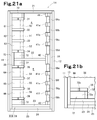
- FIG. 21a and 21b are doors 1H in which Helmholtz resonators 72 are installed in the cavities 61a, 63a, 64a, and 66a, respectively, in the door 1E of FIG.
- FIG. 21b shows an enlarged view of the XXIB portion of FIG. 21a.
- the Helmholtz resonator 72 is enlarged between the horizontal beam 21 and the auxiliary beam 31, between the auxiliary beam 34 and the horizontal beam 22, between the horizontal beam 22 and the auxiliary beam 36, and as shown in FIG.
- An enlarged hollow portion 72a provided between the crosspiece 39 and the horizontal crosspiece 23 (shown only between the auxiliary crosspiece 39 and the horizontal crosspiece 23 in FIG.
- the inner diameter of each neck 72b is smaller than the left and right width of each enlarged cavity 72a.
- each of the enlarged cavities 72 a is formed between the tip of the auxiliary rail 31 and the horizontal rail 21, between the tip of the auxiliary rail 34 and the horizontal rail 22, and between the tip of the auxiliary rail 36 and the horizontal rail 22.
- a vertical auxiliary beam 73 is installed between each of the gaps 39 and between the tip of the auxiliary beam 39 and the horizontal beam 23, and the hollow part 4 or 5 side of each cavity 61 a, 63 a, 64 a, 66 a is sealed.
- the method of forming the enlarged cavity 72a is not limited to this.
- each neck 72b is formed by providing a through hole, a vertical groove or the like penetrating each of the supplementary bars 31, 34, 36, 39 in the vertical direction. The method is not limited to this.
- the other structure of the door 1H is the same as that of the door 1E, and the same code
- the volume (cross-sectional area ⁇ length) of the neck 72b of each Helmholtz resonator 72 and the volume of the enlarged cavity 72a are adjusted as appropriate.
- the resonance frequency By adjusting the resonance frequency to a frequency at which the sound deadening performance is lowered in the cavities 61 to 66, sound waves near the resonance frequency are absorbed, and the effect of further preventing the sound deadening performance from being lowered can be obtained.
- a resonator other than the Helmholtz resonator may be provided on the door.
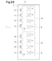
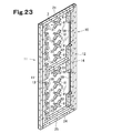
- the door 1I of FIGS. 22 and 23 is a door 1 in which a plurality of baffles 81 are provided in the hollow portions 4 and 5, respectively.
- Each baffle 81 is a member having a four-leaf plate piece extending in the four radial directions and having an X-shape in front view. Each piece extends in the direction of 40 to 50 °, preferably about 45 ° with respect to the horizontal direction.
- Each baffle 81 is fixed to the face materials 2 and 3 by adhesion or the like.
- the baffles 81 are arranged in a line at intervals in the vertical direction. There is a space between the uppermost and lowermost baffles 81 in the hollow portion 4 and the horizontal rails 21, 22, and the uppermost and lowermost baffles 81 in the hollow portion 5 and the horizontal rails 22, 23 are separated. There are also gaps in between.
- the other structure of the door 1I is the same as that of the door 1, and the same reference numerals indicate the same parts.
- each door in FIGS. 24 to 30 In the door 1I, one vent 58 is provided in each of the hollow portions 4 and 5, but a plurality of vents may be provided as in the doors of FIGS.
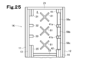
- vents 58a to 58d are provided in the hollow portion 4, and three vents 58a to 58c are provided in the door 1K of FIG. 24 and 25, the auxiliary rails 41a, 41b or 41a to 41c between the vent holes are located at the height between the baffles 81.
- the vertical position of the auxiliary rail is not limited to this.
- baffles 81 are provided in each of the hollow portions 4 and 5, but two, three, or five or more may be provided. In the door 1K of FIG. 25, three baffles 81 are installed.
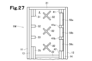
- each baffle has the same shape and the same size.
- the baffle 81 having the same radial length of each plate piece and the radial length of each plate piece.
- Different baffles 82 are used together, a baffle 81 is arranged in the middle in the vertical direction, and a baffle 82 is arranged above and below the baffle 81.
- a plate piece having a short radial length hereinafter sometimes referred to as a short piece
- the short piece is directed downward, but these may be reversed.
- the short piece of the baffle 82 is directed toward the vertical rails 11 and 13, and the short piece of the baffle 82 is directed toward the vertical rails 12 and 14 in the door 1N of FIG.
- the left and right positions of the baffles are the same and the baffles are arranged in a line in the up and down direction, but the left and right positions of the baffles may be different.
- the baffle 81 may be arranged in a zigzag shape like the door 1P of FIG.
- the size of each baffle may be varied as in the door 1Q of FIG.
- relatively large baffles 84, 85, and 86 are arranged in three upper and lower stages, and a relatively small baffle 87 is disposed between them.
- the baffle 87 is arranged on the side of the vertical bars 12 and 14 with respect to the baffles 84, 85 and 86.
- the baffles 84, 85, and 86 have short pieces, but are not limited thereto.
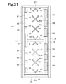
- the door 1R shown in FIG. 31 has two X-shaped baffles 81, an inverted V-shaped baffle 90, and a V-shaped baffle 91 arranged in the upper and lower hollow portions 4 and 5, respectively.
- the baffle 81 has an equal-length four-leaf plate piece, and two baffles 81 are arranged vertically in each of the hollow portions 4 and 5.
- the inverted V-shaped baffle 90 is arranged at the upper part in each hollow part 4, 5, and the V-shaped baffle 91 is arranged at the lower part in each hollow part 4, 5.
- the baffle 90 of the hollow portion 4 is separated from the horizontal beam 21, and the baffle 91 is separated from the horizontal beam 22.
- the baffle 90 of the hollow portion 5 is separated from the horizontal beam 22, and the baffle 91 is separated from the horizontal beam 23.
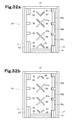
- baffles 90 and 91 instead of the baffles 90 and 91, split two-leaf type baffles 90 'and 91' separated near the bent portion of the V-shape are installed.
- the corner edges of the baffles and the auxiliary bars may be rounded or cut into a chamfered shape. If it does in this way, ventilation resistance will decrease and ventilation performance will improve.
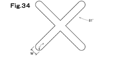
- FIG. 34 is an enlarged front view of the baffle 81 '.
- the radius of curvature r of the rounded corner edge is about 1 mm to W / 2 mm, particularly about 2 mm to W / 2 mm (see FIG. 34). Is preferred.
- the baffle 81 ′′ in FIG. 35 has a corner edge cut obliquely.
- two V-shaped baffle pieces 88a may be brought close to each other to form one substantially X-shaped baffle 88 by a pair of baffle pieces 88a.
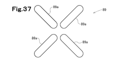
- a substantially X-shaped baffle 89 may be configured by arranging four pieces of linear pieces 89a in a star shape.
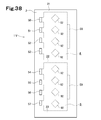
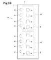
- Each of the doors 1V and 1W in FIGS. 38 and 39 is provided with a rhombus baffle 92 or a square baffle 93 instead of the X-shaped baffle 81, and the other configurations are the same as those of the door 1I. The same part is shown.
- FIGS. 40a and 40b The door 1X in FIGS. 40a and 40b is provided with elongated vents 95 and 96 in the vertical direction instead of the vents 50 to 53 and the vents 54 to 57.
- the other structure of this door 1X is the same as that of the door 1, and the same code
- baffles may be provided even in a door that does not have the baffle illustrated.
- the shape of the baffle is an example, and other shapes of baffles may be provided.
- the material of the vertical beam, horizontal beam, auxiliary beam, baffle, and face material may be any of wood, synthetic resin, metal, etc.
- the baffle may be made of a sound absorbing material.
- vents may be provided at the upper and lower portions of the door.
- a thin sound absorbing material may be stretched on the inner surface of the hollow portion.
- the front side may be an indoor side such as a toilet room or a living room, or may be an outdoor side.
- the outdoor side may be an indoor side such as a toilet room or a living room, or may be an outdoor side.
- a key may be provided on the door, and a shutter that closes when locked and opens when unlocked may be provided in the vent in conjunction with locking and unlocking of the key.
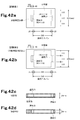
- FIGS. 42 a and 42 b are plan views of the test bodies 1 and 2
- FIGS. 42 c and 42 d are cross-sectional views of the test bodies 1 and 2.
- Example 1 (silence test 1)] 42a and 42c provided with a silencing cavity, and the specimen 2 shown in FIGS. 42b and 42d having the same structure as that of the testing body 1 except that the silencing cavity is not provided. It was measured. The results are shown in FIG. As shown in FIG. 41, the test body 1 having a silencing cavity has excellent silencing characteristics at 1/4 wavelength and 3/4 wavelength of the depth (120 mm) of the silencing cavity.
- the maximum length of the X-shaped baffle 81 (the length from the upper left end to the lower right end) is 231 mm.
- the length of one side of the V-shaped baffles 90, 91 (the length from the apex to the tip of the V-shape) is 100 mm.
- ventilation performance is improved by applying R processing or C-cut.
- the effective opening area is the order of the vents 50 to 52, the hollow portion 4 and the vents 58a to 58c in this order or vice versa when the pressure difference between the upstream side and the downstream side of the door in the venting direction is 9.8 Pa.
- the air volume passing in the direction (unit: m 3 / hr) was obtained by multiplying by 0.7.
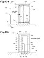
- the test apparatus 100 is provided with a chamber 101 having walls 102a to 102d erected on all sides, a ceiling 102e on the upper side, and a wall 102a on the front side provided with an entrance / exit 102f, and the chamber 101.
- a speaker 103, a microphone 104 installed outside the room 101, and the like.
- the room 101 has the same specifications as a toilet room provided in a general detached house.
- the height Fa from the ground Gr to the floor of the room is 170 mm
- the ceiling height Ha of the room is 2100 mm
- the left and right width Wa Is 850 mm and the depth Da is 1250 mm.
- the height Hb of the doorway 102f is 2000 mm
- the left-right width Wb is 600 mm.
- the center in the left-right direction of the doorway 102f matches the center in the left-right direction in the room.
- the doors 200, 200A to 200I (FIGS. 44 to 53) according to Examples 1 to 10 and the door (not shown) according to Comparative Example 1 were respectively installed at the doorway 102f so as to be openable and closable.
- the speaker 103 was arranged at a height of 400 mm from the floor surface of the chamber 101 (almost the same height as the seat surface of a general Western-style toilet) along the inner wall 102b in the chamber 101.
- the microphone 104 was placed at a height of 1.2 m from the ground Gr with a distance of 1 m from the center in the left-right direction of the outdoor side surface of the closed door in a direction orthogonal to this surface (horizontal direction).
- FIGS. 44a to 53b The configuration of the doors 200, 200A to 200I according to the first to tenth embodiments will be described with reference to FIGS. 44a to 53b.
- 44a, 45a, 46a, 47a, 48a, 49a, 50a, 51a, 52a, 53a are front views in which the face materials on the front side of the doors 200, 200A to 200I are omitted, respectively.
- 44a to 53a the lower half side of the doors 200 and 200A to 200H is omitted.
- the door frame is also omitted.
- FIGS. 44a and 44b The basic configuration of the door 200 in FIGS. 44a and 44b is the same as that of the door 1K in FIG. That is, in this door 200, like the door 1K, the hollow portion 4 is provided with three front side vent holes 50 to 52 and three rear side vent holes 58a to 58c, and the width between them. Three X-shaped baffles 81 are provided in the majority. Although not shown in detail, the hollow portion 5 is also provided with three front side vents 54 to 56 and three back side vents 58e to 58g, and is located in the wide portion between them. Three X-shaped baffles 81 are provided. In FIG. 44a, the same reference numerals as those of the door 1K indicate the same parts.
- the front and rear vents 50 to 52 and 54 to 56 have a vertical width of 167 mm and a horizontal width of 50 mm.
- the rear side vents 58a to 58c and 58e to 58g have a vertical width of 167 mm and a horizontal width of 50 mm.
- the distance from the lower surface of the horizontal beam 21 to the lower end of the auxiliary beam 31 is 178 mm, the vertical widths of the auxiliary beams 32 and 33 are each 30 mm, and the distance from the upper end of the auxiliary beam 35 to the upper surface of the horizontal beam 22 is 178 mm. is there.
- the distance from the lower surface of the horizontal beam 22 to the lower end of the auxiliary beam 35 is 178 mm
- the vertical widths of the auxiliary beams 36 and 37 are each 30 mm
- the distance from the upper end of the auxiliary beam 39 to the upper surface of the horizontal beam 23 is 178 mm. is there.
- the distance from the lower surface of the horizontal beam 21 to the lower end of the auxiliary beam 41 is 178 mm
- the vertical width of each of the auxiliary beams 41a and 41b is 30 mm
- the distance from the upper end of the auxiliary beam 42 to the upper surface of the horizontal beam 22 is 178 mm. is there.
- the distance from the lower surface of the horizontal beam 22 to the lower end of the auxiliary beam 42 is 178 mm, the vertical widths of the auxiliary beams 41d and 41e are 30 mm, respectively, and the distance from the upper end of the auxiliary beam 43 to the upper surface of the horizontal beam 23 is 178 mm. is there.
- Other dimensions (unit: mm; the same applies to FIGS. 45a to 53a) are as shown in FIGS. 44a and 44b.
- Each of the vertical beam, the horizontal beam, and each auxiliary beam constituting the door frame of the door 200 has a width (a dimension in a direction orthogonal to each longitudinal direction and a direction parallel to the extending direction of the face material) of 30 mm and a thickness (each It is made of square rod-shaped poplar LVL (Laminated Veneer ⁇ Lumber: single plate laminated material) with a dimension of 26 mm in the direction perpendicular to both the longitudinal direction and the width direction.
- a width a dimension in a direction orthogonal to each longitudinal direction and a direction parallel to the extending direction of the face material
- a thickness each It is made of square rod-shaped poplar LVL (Laminated Veneer ⁇ Lumber: single plate laminated material) with a dimension of 26 mm in the direction perpendicular to both the longitudinal direction and the width direction.
- 4mm sheet-attached MDF Medium Density Fiberboard
- the baffle 81 is made of LVL made of a poplar poplar with a width of 21mm and a thickness of 26mm.
- the door 200 was constructed by joining with a tacker and / or an adhesive (CX50 manufactured by Konishi Co., Ltd.).
- X-shaped baffles 81a smaller than the baffles 81 of the doors 200 are arranged in the upper and lower three stages in the wide portions of the hollow portions 4 and 5, respectively.
- One X-shaped baffle 81b smaller than 81a is arranged.
- the baffle 81a is disposed so that the central portion (portion where the plate pieces intersect) is located near the middle in the left-right direction of the hollow portions 4 and 5, and the baffle 81b is closer to the vertical rails 12 and 14 than the baffle 81a. Has been placed.
- the other configuration of the door 200A is the same as that of the door 200, and the same reference numerals indicate the same parts.
- two-dot chain line L 1 represents the line segment connecting the Ho ⁇ 31 distal end surface of ⁇ 33 and 35 (the surface of the hollow portion 4, 5 side) to each other
- the two-dot chain line L 2 is Ho ⁇ 41, 41a, 41b, 42 of indicate the line segment connecting the tip faces
- the two-dot chain line L 3 indicates the lower surface of the rung
- two-dot chain line L 4 are shows a top of the rung 22.
- the dimensions of the other main parts of the door 200A and the constituent materials of the parts are the same as those of the door 200.
- an X-shaped baffle 81c (in which the radial length of one leaf plate is longer than the radial length of the other three leaf plates in the wide portion of the hollow portions 4 and 5).
- an X-shaped baffle 81d (the baffle of FIG. 26) in which the radial length of adjacent two leaf pieces is longer than the radial length of the other two leaf pieces.
- 82 and a relatively small X-shaped baffle 81b (having the same shape as that used in the door 200A) are provided side by side. .
- a baffle 81c, a baffle 81b, a baffle 81d, a baffle 81b, and a baffle 81c are arranged in this order from the top.
- the uppermost baffle 81c in each of the hollow portions 4 and 5 is disposed with a long radial piece (hereinafter, also referred to as a long piece) facing the vertical rails 11 and 13 and downward.
- the middle baffle 81d is arranged with both long pieces facing the vertical rails 11 and 13, and the lowermost baffle 81c is arranged with the long pieces facing the vertical rails 11 and 13 and upward.
- the baffles 81c and 81d are respectively disposed so that the center portions are located in the vicinity of the middle in the left-right direction of the hollow portions 4 and 5, and the baffles 81b are disposed closer to the vertical rails 12 and 14 than the baffles 81c and 81d. ing.
- the other structure of this door 200B is the same as the door 200, and the same code
- one X-shaped baffle in which the radial lengths of the respective plate pieces are equal and larger than the baffle 81 of the door 200 is provided in the wide portions of the hollow portions 4 and 5, respectively.
- 81e and two X-shaped baffles 81d having the same shape as that used in the door 200B are arranged in three upper and lower stages.
- a baffle 81e is disposed at the center in the vertical direction in each of the hollow portions 4 and 5, and a baffle 81d is disposed above and below the baffle 81d.
- the upper baffle 81d in each of the hollow portions 4 and 5 is disposed with both long pieces facing downward, and the lower baffle 81d is disposed with both long pieces facing upward.
- the other structure of this door 200C is the same as that of the door 200, and the same code
- the dimensions of the other main parts of the door 200 ⁇ / b> C and the constituent materials of the parts are the same as those of the door 200.
- the X-shaped baffle 81 having the same shape as that used in the door 200 and the same one used in the door 200C are respectively provided in the wide portions of the hollow portions 4 and 5.
- Two X-shaped baffles 81e having a shape are arranged in three upper and lower stages.
- a baffle 81 is disposed in the center of each of the hollow portions 4 and 5 in the vertical direction, and baffles 81e are disposed above and below the baffle 81e.
- the other structure of this door 200D is the same as that of the door 200, and the same code
- the dimensions of the other main parts of the door 200D and the constituent materials of the parts are the same as those of the door 200.
- the radial lengths of the adjacent two-leaf plate pieces are longer than the radial lengths of the other two-leaf plate pieces, respectively, in the large width portions of the hollow portions 4 and 5.
- two X-shaped baffles 81f smaller than the baffle 81d of the door 200B and two X-shaped baffles 81 having the same shape as those used in the door 200 are arranged in four upper and lower stages.
- a baffle 81f, a baffle 81, a baffle 81, and a baffle 81f are arranged in this order from the top.
- the uppermost baffle 81f in each of the hollow portions 4 and 5 is disposed with both long pieces facing downward, and the lowermost baffle 81f is disposed with both long pieces facing upward.
- the other structure of this door 200E is the same as that of the door 200, and the same code
- the dimensions of the other main parts of the door 200E and the constituent materials of the parts are the same as those of the door 200.
- two X-shaped baffles 81e having the same shape as that used in the door 200C and one inverted V-shaped baffle are disposed in the wide portions of the hollow portions 4 and 5, respectively.
- 90 and one V-shaped baffle 91 are arranged in four upper and lower stages.
- the inverted V-shaped baffle 90 and the V-shaped baffle 91 are the same as those used in the door 1R of FIG.
- a baffle 90, a baffle 81e, a baffle 81e, and a baffle 91 are arranged in this order from the top.
- the other structure of this door 200F is the same as the door 200, and the same code
- the dimensions of the other main parts of the door 200F and the constituent materials of the parts are the same as those of the door 200.
- ⁇ Door 200G according to Embodiment 8> In the door 200G of FIGS. 51a and 51b, three X-shaped baffles 81d having the same shape as that used in the door 200B are arranged in three upper and lower stages in the wide portions of the hollow portions 4 and 5, respectively. . Each baffle 81d is arranged with both long pieces facing the vertical rails 11 and 13, respectively.
- the other structure of this door 200G is the same as that of the door 200, and the same code
- the dimensions of the other main parts of the door 200G and the constituent materials of the parts are the same as those of the door 200.
- ⁇ Door 200H according to Embodiment 9> In the door 200H of FIGS. 52a and 52b, four X-shaped baffles 81 having the same shape as that used in the door 200 are arranged in four upper and lower stages in the wide portions of the hollow portions 4 and 5, respectively. .
- the other structure of this door 200H is the same as that of the door 200, and the same code
- the dimensions of the other main parts of the door 200H and the constituent materials of the parts are also the same as those of the door 200.
- baffles 92 are arranged in a zigzag manner in the large width portions of the hollow portions 4 and 5, respectively.
- three baffles 92 are arranged in three upper and lower stages on the side of the vertical rails 11 and 13 from the middle in the left-right direction of the hollow portions 4 and 5.
- two baffles 92 are arranged in two upper and lower stages.
- Each baffle 92 on the vertical beam 12, 14 side is near the middle between the upper baffle 92 and the middle baffle 92 on the vertical beam 11, 13 side, and the middle baffle 92 and the lower baffle on the vertical beam 11, 13 side. 92, respectively.
- the middle baffle 92 on the side of the vertical rails 11 and 13 is disposed slightly closer to the vertical rails 11 and 13 than the upper and lower baffles 92 on the vertical rails 11 and 13 side.
- Each baffle 92 is disposed with the V-shaped bent portion facing the vertical rails 12 and 14.
- the other structure of this door 200I is the same as that of the door 200, and the same code
- the dimensions of the other main parts of the door 200I and the constituent materials of the parts are the same as those of the door 200.
- Comparative Example 1 As Comparative Example 1, a popular product door in which an undercut was provided so as to leave a 13 mm gap between the lower end of the door and the floor in the chamber 101 when the door was closed was used.
- ⁇ Test method> In each of the doors according to Examples 1 to 10 and Comparative Example 1, in a state where the door is closed and a state where the door is opened, the toilet drainage sound recorded in advance from the speaker 103 at a volume equivalent to the actual volume.
- the maximum noise level (Lamax) and the equivalent noise level (Laep) outside the chamber 101 were measured by the microphone 104.
- the interior of the door is provided with a hollow portion
- the front side and the back side of the door are each provided with a front side vent and a rear side vent that communicate with the hollow portion.
- the opening and the rear side vent are arranged on the door side opposite to each other, and the hollow portions in the vicinity of the front side vent and in the vicinity of the rear side vent are defined as small portions having a small vertical width, and the hollow portion therebetween Is a large large portion having a large vertical width, and the doors of Examples 1 to 10 in which baffles are provided in the large large portion exhibit a high noise reduction effect.
- Example 7 inverted V-shaped and V-shaped baffles 90 and 91 and two X-shaped baffles 81e are provided, and four X-shaped baffles 81 having the same shape are equally arranged in four upper and lower stages.
- Example 9 and Example 10 in which five lateral V-shaped baffles 92 were arranged in a zigzag shape, a higher noise reduction effect was exhibited.
Landscapes
- Engineering & Computer Science (AREA)
- Civil Engineering (AREA)
- Structural Engineering (AREA)
- Specific Sealing Or Ventilating Devices For Doors And Windows (AREA)
- Securing Of Glass Panes Or The Like (AREA)
- Special Wing (AREA)
- Soundproofing, Sound Blocking, And Sound Damping (AREA)
Description
本発明は、トイレルームや居室などの出入口に設けられるドアに係り、特に換気用の中空部及び通気口を備えたドアに関する。
ドア内部を中空部とし、ドアの正面側及び背面側の面材にそれぞれ通気口を設けて換気機能をもたせたドアが特許文献1,2に記載されている。この特許文献1,2にあっては、正面側及び背面側の通気口のうちの一方をドア上部に設け、他方をドア下部に設けて中空部を上下に延在させている。また、中空部内に吸音材を内張りして防音機能ももたせている。特許文献1の図3には、通気口の一方をドアの一方の側辺に沿って設け、他方の通気口を他方の側辺に沿って設けることが記載されている。
上記特許文献1,2のように、中空部内に吸音材を内張りすると、中空部のドア厚さ方向の寸法が小さくなり、通気量が減少し、換気機能が低下する。
本発明は、換気機能及び防音機能に優れたドアを提供することを目的とする。
また、特許文献1,2にあっては、ドア内部が中空部となっており、通気口近傍では面材がドア枠で裏打ちされていないため、通気口近傍部分における面材の強度、剛性が不足し、面材が損傷し易くなったり、振動し易くなる等の短所があった。
本発明は、その一態様において、通気口近傍部分における面材の強度及び剛性が高いドアを提供することを目的とする。
本発明のドアは、ドア内部に中空部が設けられ、ドアの一方の面と他方の面にそれぞれ該中空部に連通した通気口が設けられており、一方の第1の通気口はドアの一側に配置され、他方の第2の通気口はドアの他側に配置されているドアにおいて、該第1の通気口近傍の該中空部が、第1及び第2の通気口同士を結ぶ方向と交差方向の幅が小さい第1の幅小部となっており、第2の通気口近傍の該中空部が、該交差方向の幅が小さい第2の幅小部となっており、該第1の幅小部と第2の幅小部との間が、該第1及び第2の幅小部よりも該交差方向の幅が大きい幅大部となっていることを特徴とする。
本発明では、通気口はドアの一辺に沿って延在していてもよい。
本発明のドアは、前記中空部を囲むドア枠の両側にそれぞれ面材を設けたものであり、該面材にそれぞれ前記通気口が設けられており、該ドア枠はドアの周縁に沿う縦桟及び横桟と、該縦桟又は横桟に沿う複数の補桟とを有しており、補桟同士が間隔をあけて配置され、該補桟同士の間に前記幅小部が形成されていてもよい。
前記面材のうち前記通気口近傍部分が、前記補桟と結合されていることが好ましい。
前記中空部内のうち、第1の通気口と第2の通気口との間の位置に、該中空部の前記交差方向の幅を小さくするバッフルが設けられていてもよい。
この場合、複数の前記バッフルが前記交差方向に間隔をあけて配設されていることが好ましい。
前記バッフルは、V字形又は放射方向に延在した3葉以上の板材を有したものであってもよい。
本発明のドアにあっては、正面側及び背面側の面材にそれぞれ設けられた通気口と、ドア内の中空部とを介して換気が行われる。本発明では、中空部が、通気口近傍において幅小部となっており、この幅小部同士の間が幅大部となっており、音波がこの幅小部から幅大部に入るときに、中空部の断面積が急激に拡大することによって消音作用が奏される。
本発明のドアにあっては、ドア枠の補桟に通気口近傍を結合して支持させることにより、通気口近傍における面材の強度及び剛性が高くなる。
以下、図面を参照して実施の形態について説明する。
[図1~6のドア]
図1~6のドア1は、ドア枠10の一方の側に正面側面材2を取り付け、他方の側に背面側面材3を取り付けたものである。
図1~6のドア1は、ドア枠10の一方の側に正面側面材2を取り付け、他方の側に背面側面材3を取り付けたものである。
ドア枠10は、図2の通り、長方形枠状であり、ドア1の縦側辺に沿う1対の第1縦桟11,12と、該第1縦桟11,12の内側に沿う第2縦桟13,14と、ドア1の上辺に沿う第1横桟21と、ドア1の上下方向中間の第2横桟22と、それぞれドア1の下辺に沿う第3横桟23、第4横桟24及び第5横桟25とを有している。
左側の縦桟11,13と右側の縦桟12,14の上端間が横桟21によって連結され、下端間が横桟23,24,25によって連結されている。
縦桟13のドア内側の側面に短尺の補桟31~39が上下に間隔をあけて取り付けられている。また縦桟14のドア内側の側面に、短尺の補桟41,42,43が上下に間隔をあけて取り付けられている。この実施の形態では各補桟31~39はそれぞれ2本ずつひき揃えて縦桟13に取り付けられており、また補桟41~43もそれぞれ2本ずつ引き揃えて縦桟14に取り付けられている。
補桟35と補桟42との間に前記横桟22が架設されている。
最上位の補桟31,41の上端面は横桟21の下面に当接している。最下位の補桟39,43の下端面は横桟23の上面に当接している。縦桟11~14、横桟21~25、補桟31~39、41~43の当接部分又は重なり合い部分はタッカー、釘、ビス、接着剤などの連結手段によって連結されている。金属材料にて縦桟、横桟及び補桟が構成されているときには、連結手段は溶接であってもよい。
また、1つの板材から縦桟、横桟、補桟を削り出してもよいし、樹脂、金属などを一体で成形、鋳造してもよい。
正面側の面材2には、通気口50~57が設けられている。通気口50は補桟31,32間に位置しており、以下同様に通気口51~57が各補桟32,33間、補桟33,34間、補桟34,35間、補桟35,36間、補桟36,37間、補桟37,38間、補桟38,39間に位置している。
通気口50の上下寸法は、補桟31,32間の上下寸法に合致し、以下同様に通気口51~57の上下寸法は補桟32,33間、補桟33,34間、補桟34,35間、補桟35,36間、補桟36,37間、補桟37,38間、補桟38,39間の上下寸法に合致している。通気口50の上縁は補桟31の下縁に合致し、以下同様に通気口51~57の上縁は補桟32~38の下縁に合致している。通気口50の下縁は補桟32の上縁に合致し、以下同様に通気口51~57の下縁は補桟33~39の上縁に合致している。
通気口50~57の左右幅は、補桟31の2本分の幅よりも狭いものとなっている。通気口50~57のドアサイド側の側辺は縦桟13のドア中央側の側辺に合致している。
通気口58,59の上下寸法はそれぞれ補桟41,42間、補桟42,43間の上下寸法と合致している。通気口58,59の上縁は補桟41,42の下縁に合致している。通気口58,59の下縁は補桟42,43の上縁に合致している。通気口58,59の左右幅は、各補桟41,42,43の2本分の幅よりも狭いものとなっている。通気口58,59のドアサイド側の側辺は縦桟14のドア中央側の側辺に合致している。
面材2,3はドア枠10に対して接着、ビス留めなどの固着手段によって取り付けられている。
このように構成されたドア1にあっては、面材2,3とドア枠10とによって囲まれた中空部4又は5(図2)、正面側通気口50~57及び背面側通気口58,59を介してドア1の正面側と背面側とが連通し、換気が行われる。この実施の形態では、通気口50~57及び通気口58,59が各々ドア側辺に沿って縦一列に設けられており、通気口50~57から通気口58,59までの距離が短い。そのため、中空部4,5を通過する通気抵抗が小さく、換気性能が良好である。
この実施の形態では、補桟31,32間、補桟32,33間、補桟33,34間、補桟34,35間、補桟35,36間、補桟37,38間、補桟38,39間が幅寸法d1の幅小部となっている。また、中空部4の横桟21,22間が幅寸法d2の幅大部となっており、中空部5の横桟22,23間が幅寸法d3の幅大部となっている。そのため、通気口50~57から中空部4又は5に入る音波は、幅寸法d1の幅小部から幅寸法d2又はd3の幅大部へ入るときに断面積が急激に拡大することによって消音が行われる。
補桟41,42間の幅小部の上下寸法d4が中空部4の幅大部の上下寸法d2に比べて小さく、補桟42,43間の幅小部の上下寸法d5が中空部5の幅大部の上下寸法d3に比べて小さいので、通気口58,59から中空部4,5へ入る音波の消音が行われる。
この実施の形態では、面材2,3の各通気口50~59の上下両側部分がそれぞれ補桟31~39,41~43によって支持されているので、通気口50~59近傍における面材2,3の強度及び剛性が高い。そのため、面材2,3の損傷が防止されると共に、面材2,3の振動も抑制される。
この実施の形態では、図示の通り、ドア1の四辺の外周をそれぞれ一直線状としており、切欠状部などを設けていないので、ドアを閉めたときにドア枠との間に生じる隙間が小さく、音が隙間から漏れることが防止される。また、該切欠状部に物が挟み込まれることもない。
[図7~9のドア]
本発明では、ドア正面側及び背面側の通気口の数は図1以外であってもよい。図7~9のドア1Aは、正面側の通気口の数を6個とし、背面側の通気口の数を4個としたものである。正面側の通気口50,51間、通気口51,52間、通気口54,55間、通気口55,56間にそれぞれ補桟32,33,36,37が配置されている。背面側の通気口としては、上側の中空部4に連通する通気口58A,58Bと、下側の中空部5に連通する通気口59A,59Bとが設けられている。通気口58A,58B間に補桟41Aが配置され、通気口59A,59B間に補桟41Bが配置されている。
本発明では、ドア正面側及び背面側の通気口の数は図1以外であってもよい。図7~9のドア1Aは、正面側の通気口の数を6個とし、背面側の通気口の数を4個としたものである。正面側の通気口50,51間、通気口51,52間、通気口54,55間、通気口55,56間にそれぞれ補桟32,33,36,37が配置されている。背面側の通気口としては、上側の中空部4に連通する通気口58A,58Bと、下側の中空部5に連通する通気口59A,59Bとが設けられている。通気口58A,58B間に補桟41Aが配置され、通気口59A,59B間に補桟41Bが配置されている。
このドア1Aのその他の構成はドア1と同一であり、同一符号は同一部分を示している。このドア1Aはドア1と同様の効果を有する。なお、通気口58A,58Bの間に補桟41Aが配置され、通気口59A,59Bの間に補桟41Bが配置されており、この補桟によってドア1Aの強度、剛性が向上している。図示は省略するが、正面側通気口及び背面側通気口の数はドア1,1A以外であってもよい。
[図10~12のドア]
図10~12のドア1Bは、前記ドア1において補桟31~34,36~39をそれぞれ1本ずつ設けたものであり、各補桟31~34,36~39は縦桟13から離隔して縦桟に沿って配置されている。従って、縦桟13と補桟31~34との間、及び縦桟13と補桟36~39との間には、上下に一連となった長い空間部K(図11)が延在している。
図10~12のドア1Bは、前記ドア1において補桟31~34,36~39をそれぞれ1本ずつ設けたものであり、各補桟31~34,36~39は縦桟13から離隔して縦桟に沿って配置されている。従って、縦桟13と補桟31~34との間、及び縦桟13と補桟36~39との間には、上下に一連となった長い空間部K(図11)が延在している。
なお、図11では、補桟31~34,36~39が縦桟13から離隔しているが、補桟31,39は縦桟13に接触し、補桟32~34,36~38のみ縦桟13から離隔していてもよい。
このドア1Bのその他の構成はドア1と同一であり、同一符号は同一部分を示している。
[図13~15のドア]
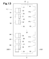
図13~15のドア1Cにあっては、正面側通気口50~52,54~56の両側に配置する補桟31~33,35~37,39のドア幅方向の長さが前記各ドア1,1A,1Bの補桟よりも大きい。各通気口50~52,54~56は、補桟31~33,35~37,39の先端側すなわち中空部4又は5側に配置されている。これにより、各通気口50~52,54~56よりもドアサイド側(縦桟13側)に空洞部61~66が形成されている。空洞部61~66は、1対の補桟と縦桟13とによって3方が囲まれ、残りの一方が中空部4又は5に向って開放している。
図13~15のドア1Cにあっては、正面側通気口50~52,54~56の両側に配置する補桟31~33,35~37,39のドア幅方向の長さが前記各ドア1,1A,1Bの補桟よりも大きい。各通気口50~52,54~56は、補桟31~33,35~37,39の先端側すなわち中空部4又は5側に配置されている。これにより、各通気口50~52,54~56よりもドアサイド側(縦桟13側)に空洞部61~66が形成されている。空洞部61~66は、1対の補桟と縦桟13とによって3方が囲まれ、残りの一方が中空部4又は5に向って開放している。
空洞部61~66の深さ、即ち通気口50~52,54~56のドアサイド側の縁部から空洞部61~66の最奥部(縦桟13)までの距離Eをλ/4とすることにより、波長λの音を効率よく消音することができる。
なお、このドア1Cでは、上側の中空部4に3個の正面側通気口50~52と4個の背面側通気口58a~58dが設けられ、下側の中空部5に3個の正面側通気口54~56と4個の背面側通気口58e~58hが設けられている。通気口58a,58b間、通気口58b,58c間、通気口58c,58d間にそれぞれ補桟41a~41cが配置され、通気口58e,58f間、通気口58f,58g間、通気口58g,58h間にそれぞれ補桟41d~41fが配置されている。ただし、通気口の数はこれに限定されない。ドア1Cのその他の構成はドア1と同様であり、同一符号は同一部分を示している。
[図16~21の各ドア]
図16~21は、それぞれ空洞部を有した別構造のドア1D~1G,1G’,1Hを示すものであり、正面側の面材を取り除いた状態の正面図を示している。
図16~21は、それぞれ空洞部を有した別構造のドア1D~1G,1G’,1Hを示すものであり、正面側の面材を取り除いた状態の正面図を示している。
図16のドア1Dにあっては、補桟から空洞部内に突出する突起70を備えている。各突起70は、空洞部61~66の入口側の上下方向幅を狭めるように設けられている。空洞部61~63にあっては、突起70は各空洞部61~63の上側の補桟31~33から下方に向って突設されている。空洞部64~66にあっては、突起70は各空洞部64~66の下側の補桟36,37,39から上方に向って突設されている。
ドア1Dのその他の構成はドア1Cと同様であり、同一符号は同一部分を示している。
図17のドア1Eは、補桟31と横桟21との間に空洞部61aを設け、補桟34と横桟22との間に空洞部63aを設け、補桟36と横桟22との間に空洞部64aを設け、補桟39と横桟23との間に空洞部66aを設けたものである。
即ち、ドア1Eでは、補桟31は横桟21から離隔して配置され、補桟39は横桟23から離隔して配置され、これらの間がそれぞれ空洞部61a,66aとなっている。補桟31,35間、補桟35,39間にそれぞれ上下に間隔をあけて3個の補桟32~34,36~38が配設されており、補桟31,32間、補桟32,33間、補桟33,34間、補桟36,37間、補桟37,38間、補桟38,39間にそれぞれ通気口50~52,54~56が設けられると共に、これらの間の通気口50~52,54~56よりもドアサイド側がそれぞれ空洞部61~66となっている。補桟34,36はそれぞれ補桟35の上端及び下端に当接している。補桟35の先端面は補桟34,36の先端面よりもドアサイド側に後退しており、この補桟35の先端面よりも中空部4又は5側の補桟34と横桟22との間及び横桟22と補桟36との間がそれぞれ空洞部63a,64aとなっている。ドア1Eのその他の構成はドア1Cと同様であり、同一符号は同一部分を示している。
空洞部61a,66aの深さE1は空洞部61~66の深さEよりも大きい。空洞部63a,64aの深さE2はE<E2<E1の関係を満たすものとなっている。このように空洞部61~66とは深さの異なる空洞部61a,66a及び空洞部63a,64aを設けたことにより、消音できる音の周波数域が広がる。
図18のドア1Fは、図17に示すドア1Eにおいて、各補桟31~33,37~39に突起70を設けたものである。突起70の設置形態は図16のドア1Dと同一である。
図19のドア1Gは、補桟31~34,36~39を斜めに設置し、空洞部61~66の深さを大きくするように構成したものである。ドア1Gのその他の構成はドア1Eと同一であり、同一符号は同一部分を示している。
図20のドア1G’は、図19のドア1Gから空洞部61a,63a,64a,66aを省略したものとなっている。
詳しくは、このドア1G’では、横桟21,22間、横桟22,23間にそれぞれ上下に間隔をあけて4個の補桟31~34,36~39が配設されている。補桟31の上端は横桟21の下面に当接しており、補桟34の下端は横桟22の上面に当接しており、補桟36の上端は横桟22の下面に当接しており、補桟39の下端は横桟23の上面に当接している。このドア1G’では、補桟35は省略されており、横桟22は縦桟13と補桟42との間に架設されている。補桟31の下面及び補桟34の上面は、それぞれ、ドアサイド側ほど上位となるように傾斜しており、補桟32,33は、これらの補桟31の下面及び補桟34の上面と略平行に斜めに設置されている。補桟36の下面及び補桟39の上面は、それぞれ、ドアサイド側ほど下位となるように傾斜しており、補桟37,38は、これらの補桟36の下面及び補桟39の上面と略平行に斜めに設置されている。補桟31,32間、補桟32,33間、補桟33,34間、補桟36,37間、補桟37,38間、補桟38,39間にそれぞれ通気口50~52,54~56が設けられると共に、これらの間の通気口50~52,54~56よりもドアサイド側がそれぞれ空洞部61~66となっている。ドア1G’のその他の構成はドア1Gと同様であり、同一符号は同一部分を示している。
図21a,21bのドア1Hは、図17のドア1Eにおいて、空洞部61a,63a,64a,66aにそれぞれヘルムホルツ共鳴器72を設置したものである。図21bは図21aのXXIB部分を拡大して示している。ヘルムホルツ共鳴器72は、図21bに拡大して示すように、横桟21と補桟31との間、補桟34と横桟22との間、横桟22と補桟36との間及び補桟39と横桟23との間(図21bでは補桟39と横桟23との間のみ図示。)にそれぞれ設けられた、中空部4又は5に直接的に連通しない拡大空洞部72aと、各拡大空洞部72aとこれらに隣接する空洞部61,63,64,66とをそれぞれ連通したダクト状の頚部72bとからなる。各頚部72bの内径は、各拡大空洞部72aの左右幅よりも小さいものとなっている。この実施の形態では、各拡大空洞部72aは、補桟31の先端と横桟21との間、補桟34の先端と横桟22との間、補桟36の先端と横桟22との間及び補桟39の先端と横桟23との間にそれぞれ縦補桟73を架設し、各空洞部61a,63a,64a,66aの中空部4又は5側を封鎖することにより形成されているが、拡大空洞部72aの形成方法はこれに限定されない。この実施の形態では、各頚部72bは、各補桟31,34,36,39に、これらを上下方向に貫通する貫通孔や縦溝等を設けることにより形成されているが、頚部72bの形成方法はこれに限定されない。ドア1Hのその他の構成はドア1Eと同一であり、同一符号は同一部分を示している。このヘルムホルツ共鳴器72付きドア1Hにあっては、各ヘルムホルツ共鳴器72の頸部72bの体積(断面積×長さ)と拡大空洞部72aの体積とを適宜調整し、各ヘルムホルツ共鳴器72の共鳴周波数を、空洞部61~66では消音性能の低下する周波数に合わせることにより、この共鳴周波数付近の音波が吸音され、消音性能の低下をより一層防止する効果が得られる。なお、ヘルムホルツ共鳴器以外の共鳴器をドアに設けてもよい。
[図22,23のドア]
図22,23のドア1Iは、ドア1において、中空部4,5にそれぞれ複数個のバッフル81を設けたものである。各バッフル81は、放射4方向に延出する4葉の板片を有した正面視形状がX字状の部材である。各板片は水平方向に対し40~50°好ましくは約45°の方向に延在している。各バッフル81は面材2,3に接着等により固着されている。バッフル81は上下に間隔をあけて1列に配列されている。中空部4内の最上位及び最下位のバッフル81と横桟21,22との間に間隔があいており、中空部5内の最上位及び最下位のバッフル81と横桟22,23との間にも間隔があいている。
図22,23のドア1Iは、ドア1において、中空部4,5にそれぞれ複数個のバッフル81を設けたものである。各バッフル81は、放射4方向に延出する4葉の板片を有した正面視形状がX字状の部材である。各板片は水平方向に対し40~50°好ましくは約45°の方向に延在している。各バッフル81は面材2,3に接着等により固着されている。バッフル81は上下に間隔をあけて1列に配列されている。中空部4内の最上位及び最下位のバッフル81と横桟21,22との間に間隔があいており、中空部5内の最上位及び最下位のバッフル81と横桟22,23との間にも間隔があいている。
このドア1Iのその他の構成はドア1と同一であり、同一符号は同一部分を示している。
このドア1Iにあっては、バッフル81同士の間の間隔及び横桟21,22,23と直近のバッフル81との間隔が中空部4,5の幅大部の上下寸法d2,d3よりも小さいので、音波がこの小間隔部を通るときに消音効果が奏される。また、面材2,3同士がバッフル81によって連結されるので、面材2,3の強度及び剛性が高い。
[図24~30の各ドア]
上記ドア1Iでは通気口58が各中空部4,5に1個ずつ設けられているが、図24~30のドアのように複数個の通気口が設けられてもよい。
上記ドア1Iでは通気口58が各中空部4,5に1個ずつ設けられているが、図24~30のドアのように複数個の通気口が設けられてもよい。
図24のドア1Jでは、中空部4に4個の通気口58a~58dが設けられ、図25のドア1Kでは3個の通気口58a~58cが設けられている。図24,25では、通気口間の補桟41a,41b又は41a~41cが各バッフル81同士の間の高さに位置している。ただし、補桟の上下方向の位置はこれに限定されない。
上記ドア1Iではバッフル81は中空部4,5にそれぞれ4個ずつ設置されているが、2個、3個又は5個以上設けられてもよい。図25のドア1Kでは3個のバッフル81が設置されている。
X字形のバッフルの形状や大きさは同一であってもよく、異なってもよい。上記のドア1I~1Kでは各バッフルは同一形状、同一大きさであるが、図26のドア1Lでは、各板片の放射方向長さの等しいバッフル81と、各板片の放射方向長さの異なるバッフル82とを併用しており、上下方向の中間にバッフル81が配置され、その上下にバッフル82が配置されている。上側のバッフル82では放射方向長さの短い板片(以下、短片ということがある。)を上向きとし、下側のバッフル82では短片を下向きとしているが、これらをそれぞれ逆向きとしてもよい。
図27のドア1Mでは、バッフル82の短片を縦桟11,13側に向けており、図28のドア1Nではバッフル82の短片を縦桟12,14側に向けている。
上記各ドア1I~1Nでは、各バッフルの左右方向位置を同一とし、バッフルを上下方向に1列に揃えているが、各バッフルの左右方向位置を異ならせてもよい。例えば、図29のドア1Pのようにジグザグ状にバッフル81を配置してもよい。この場合も、図30のドア1Qのように、各バッフルの大きさを異ならせてもよい。ドア1Qでは、比較的大きいバッフル84,85,86を上下3段に配置し、それらの間に比較的小さいバッフル87を配置している。バッフル87は、バッフル84,85,86よりも縦桟12,14側に配置している。バッフル84,85,86は短片を有したものとなっているが、これに限定されない。
[図31のドア]
図31のドア1Rは、上下の各中空部4,5にそれぞれX字形の2個のバッフル81と、逆V字形のバッフル90と、V字形のバッフル91とを配置したものである。バッフル81は、前述の通り、等長の4葉の板片を有しており、各中空部4,5に上下に2個配置されている。逆V字形バッフル90は、各中空部4,5内の上部に配置され、V字形バッフル91は各中空部4,5内の下部に配置されている。中空部4のバッフル90は横桟21から離隔し、バッフル91は横桟22から離隔している。中空部5のバッフル90は横桟22から離隔し、バッフル91は横桟23から離隔している。
図31のドア1Rは、上下の各中空部4,5にそれぞれX字形の2個のバッフル81と、逆V字形のバッフル90と、V字形のバッフル91とを配置したものである。バッフル81は、前述の通り、等長の4葉の板片を有しており、各中空部4,5に上下に2個配置されている。逆V字形バッフル90は、各中空部4,5内の上部に配置され、V字形バッフル91は各中空部4,5内の下部に配置されている。中空部4のバッフル90は横桟21から離隔し、バッフル91は横桟22から離隔している。中空部5のバッフル90は横桟22から離隔し、バッフル91は横桟23から離隔している。
このドア1Rのその他の構成はドア1Iと同一であり、同一符号は同一部分を示している。
[図32a,32bのドア]
図32aのドア1Sでは、V字形バッフル91を各中空部4,5内の上部に配置し、逆V字形バッフル90を各中空部4,5内の下部に配置している。
図32aのドア1Sでは、V字形バッフル91を各中空部4,5内の上部に配置し、逆V字形バッフル90を各中空部4,5内の下部に配置している。
図32bのドア1Tでは、バッフル90,91の代わりに、V字の屈曲部付近で分離した、分割2葉型のバッフル90’,91’を設置している。
ドア1S,1Tのその他の構成はドア1Rと同一であり、同一符号は同一部分を示している。
[図33~37のドア及びバッフル]
本発明では、バッフルや補桟の角縁を丸みづけしたり、面取り状にカットした形状としてもよい。このようにすると、通気抵抗が減少し、換気性能が向上する。
本発明では、バッフルや補桟の角縁を丸みづけしたり、面取り状にカットした形状としてもよい。このようにすると、通気抵抗が減少し、換気性能が向上する。
図33のドア1Uでは、バッフル81’と各補桟31~33,35~37,39,41~43,41a~41fの角縁を丸みづけしている。図34はこのバッフル81’の拡大正面図である。
バッフルの各板片の延在方向と直交方向の幅をWとした場合、丸みづけした角縁部の曲率半径rは、1mm~W/2mm特に2mm~W/2mm程度(図34参照)が好適である。
図35のバッフル81’’は角縁部を斜めにカットしたものである。
本発明では、図36のように、2片のV字形バッフル片88aを近接させ、1対のバッフル片88aによって1個の略X字形のバッフル88を構成してもよい。また、図37のように、4片の直線片89aをスター状に配列することによって略X字状のバッフル89を構成してもよい。
[図38,39の各ドア]
図38,39の各ドア1V,1WはX字状のバッフル81の代わりに菱形のバッフル92又は方形のバッフル93を設けたものであり、その他の構成はドア1Iと同一であり、同一符号は同一部分を示している。
図38,39の各ドア1V,1WはX字状のバッフル81の代わりに菱形のバッフル92又は方形のバッフル93を設けたものであり、その他の構成はドア1Iと同一であり、同一符号は同一部分を示している。
[図40a,40bのドア]
図40a,40bのドア1Xは、通気口50~53、通気口54~57の代わりに上下に細長い通気口95,96を設けたものである。このドア1Xのその他の構成はドア1と同一であり、同一符号は同一部分を示している。
図40a,40bのドア1Xは、通気口50~53、通気口54~57の代わりに上下に細長い通気口95,96を設けたものである。このドア1Xのその他の構成はドア1と同一であり、同一符号は同一部分を示している。
[さらに別の実施の形態]
図示のバッフルを有しないドアにおいても上記いずれかのバッフルを設けてもよい。
図示のバッフルを有しないドアにおいても上記いずれかのバッフルを設けてもよい。
上記のバッフルの形状は一例であり、その他の形状のバッフルを設けてもよい。
縦桟、横桟、補桟、バッフル、面材の材質は木材、合成樹脂、金属などのいずれであってもよい。バッフルは吸音性の素材にて構成されてもよい。
補桟の数は図示以外であってもよいことは明らかである。
本発明では、通気口をドアの上部と下部とに設けてもよい。
本発明では、中空部の内面に薄い吸音材を張ってもよい。
本発明のドアは、正面側をトイレルーム、居室などの室内側としてもよく、室外側としてもよいが、通気口の数が多い方の面材を室外側とした方が良い場合もある。
本発明では、ドアに鍵を設けると共に、鍵のロック、アンロックに連動してロック時に閉、アンロック時に開となるシャッタを通気口に設けるようにしてもよい。
図42a~42dに示す試験体1,2を用いて、本発明の効果を実証するための実験を行った。なお、図42a,42bは試験体1,2の平面図、図42c,42dは試験体1,2の断面図である。
[実験1(消音試験1)]
消音用空洞部を設けた図42a,42cに示す試験体1と、消音用空洞部を有しないこと以外は試験体1と同一構造の図42b,42dに示す試験体2とについて音響透過損失を測定した。結果を図41に示す。図41の通り、消音用空洞部を有する試験体1は消音用空洞部の深さ(120mm)の1/4波長及び3/4波長において消音特性に優れる。
消音用空洞部を設けた図42a,42cに示す試験体1と、消音用空洞部を有しないこと以外は試験体1と同一構造の図42b,42dに示す試験体2とについて音響透過損失を測定した。結果を図41に示す。図41の通り、消音用空洞部を有する試験体1は消音用空洞部の深さ(120mm)の1/4波長及び3/4波長において消音特性に優れる。
[実験2(通気量測定試験)]
図24,27,31に示すドアの中空部4に対し通風を行い、通気量を測定した。中空部4の高さ(横桟21,22間距離)は918mm、幅(補桟31~35と補桟41,41a,41b,42との間の距離)は167mm、厚さ(面材2,3間距離)は26mmである。
図24,27,31に示すドアの中空部4に対し通風を行い、通気量を測定した。中空部4の高さ(横桟21,22間距離)は918mm、幅(補桟31~35と補桟41,41a,41b,42との間の距離)は167mm、厚さ(面材2,3間距離)は26mmである。
X字状バッフル81の最大長さ(左上端から右下端までの長さ)は231mmである。V字形バッフル90,91の一辺の長さ(V字の頂点から先端までの長さ)は100mmである。
結果を表1に示す。なお、表1でR加工なしとは補桟及びバッフルの角縁を直角としたもの、R加工ありとは図34の通り丸みづけしたもの、Cカットとは図35の通り斜めにカットしたものである。

表1の通り、R加工又はCカットを施すことにより通気性能(換気性能)が向上する。なお、有効開口面積は、ドアの通気方向上流側と下流側との圧力差が9.8Paのときに通気口50~52、中空部4及び通気口58a~58cをこの順に又はこれとは逆向きに通過する風量(単位:m3/hr)に0.7を乗じて求めた。
[実験3(消音試験2)]
図43a,43bに示す試験装置100を用いて本発明のドアの消音性能を検証した。
図43a,43bに示す試験装置100を用いて本発明のドアの消音性能を検証した。
<試験装置100>
試験装置100は、四方に壁102a~102dが立設され、上方を天井102eによって塞がれており、正面側の壁102aに出入口102fが設けられた室101と、該室101内に設置されたスピーカ103と、室101外に設置されたマイク104等を備えている。室101は、一般的な戸建て住宅に設けられるトイレルームと同様の仕様となっており、地面Grから室内の床面までの高さFaは170mm、室内の天井高さHaは2100mm、左右幅Waは850mm、奥行きDaは1250mmである。出入口102fの高さHbは2000mm、左右幅Wbは600mmである。出入口102fの左右方向の中央は、室内の左右方向の中央と合致している。
試験装置100は、四方に壁102a~102dが立設され、上方を天井102eによって塞がれており、正面側の壁102aに出入口102fが設けられた室101と、該室101内に設置されたスピーカ103と、室101外に設置されたマイク104等を備えている。室101は、一般的な戸建て住宅に設けられるトイレルームと同様の仕様となっており、地面Grから室内の床面までの高さFaは170mm、室内の天井高さHaは2100mm、左右幅Waは850mm、奥行きDaは1250mmである。出入口102fの高さHbは2000mm、左右幅Wbは600mmである。出入口102fの左右方向の中央は、室内の左右方向の中央と合致している。
この出入口102fに、実施例1~10に係るドア200,200A~200I(図44~53)及び比較例1に係るドア(図示略)をそれぞれ開閉可能に設置した。
スピーカ103は、室101内の奥側の壁102bに沿って、室101の床面から400mmの高さ(一般的な洋風便器の座面とほぼ同じ高さ)に配置した。マイク104は、閉じた状態のドアの室外側の面の左右方向の中央からこの面と直交方向(水平方向)に1m離隔して、地面Grから1.2mの高さに配置した。
[実施例1~10]
図44a~53bを参照して、実施例1~10に係るドア200,200A~200Iの構成について説明する。図44a,45a,46a,47a,48a,49a,50a,51a,52a,53aは、それぞれ、ドア200,200A~200Iの正面側の面材を省略した正面図である。なお、図44a~53aでは、ドア200,200A~200Hの下半側は省略されている。また、図45a~53aでは、ドア枠も省略されている。
図44a~53bを参照して、実施例1~10に係るドア200,200A~200Iの構成について説明する。図44a,45a,46a,47a,48a,49a,50a,51a,52a,53aは、それぞれ、ドア200,200A~200Iの正面側の面材を省略した正面図である。なお、図44a~53aでは、ドア200,200A~200Hの下半側は省略されている。また、図45a~53aでは、ドア枠も省略されている。
<実施例1に係るドア200>
図44a,44bのドア200の基本的な構成は、図25のドア1Kと同様となっている。即ち、このドア200では、ドア1Kと同様に、中空部4に、3個の正面側通気口50~52と、3個の背面側通気口58a~58cとが設けられ、それらの間の幅大部内に3個のX字形のバッフル81が設けられている。また、詳しい図示は省略するが、中空部5にも、3個の正面側通気口54~56と、3個の背面側通気口58e~58gとが設けられ、それらの間の幅大部内に3個のX字形のバッフル81が設けられている。図44aにおいて、ドア1Kと同一符号は同一部分を示している。各正面側通気口50~52,54~56の上下幅は167mmであり、左右幅は50mmである。各背面側通気口58a~58c,58e~58gの上下幅は167mmであり、左右幅は50mmである。横桟21の下面から補桟31の下端までの距離は178mmであり、補桟32,33の上下幅はそれぞれ30mmであり、補桟35の上端から横桟22の上面までの距離は178mmである。横桟22の下面から補桟35の下端までの距離は178mmであり、補桟36,37の上下幅はそれぞれ30mmであり、補桟39の上端から横桟23の上面までの距離は178mmである。横桟21の下面から補桟41の下端までの距離は178mmであり、補桟41a,41bの上下幅はそれぞれ30mmであり、補桟42の上端から横桟22の上面までの距離は178mmである。横桟22の下面から補桟42の下端までの距離は178mmであり、補桟41d,41eの上下幅はそれぞれ30mmであり、補桟43の上端から横桟23の上面までの距離は178mmである。これ以外の主要各部の寸法(単位:mm。図45a~53aでも同様。)は、図44a,44bに記載の通りである。
図44a,44bのドア200の基本的な構成は、図25のドア1Kと同様となっている。即ち、このドア200では、ドア1Kと同様に、中空部4に、3個の正面側通気口50~52と、3個の背面側通気口58a~58cとが設けられ、それらの間の幅大部内に3個のX字形のバッフル81が設けられている。また、詳しい図示は省略するが、中空部5にも、3個の正面側通気口54~56と、3個の背面側通気口58e~58gとが設けられ、それらの間の幅大部内に3個のX字形のバッフル81が設けられている。図44aにおいて、ドア1Kと同一符号は同一部分を示している。各正面側通気口50~52,54~56の上下幅は167mmであり、左右幅は50mmである。各背面側通気口58a~58c,58e~58gの上下幅は167mmであり、左右幅は50mmである。横桟21の下面から補桟31の下端までの距離は178mmであり、補桟32,33の上下幅はそれぞれ30mmであり、補桟35の上端から横桟22の上面までの距離は178mmである。横桟22の下面から補桟35の下端までの距離は178mmであり、補桟36,37の上下幅はそれぞれ30mmであり、補桟39の上端から横桟23の上面までの距離は178mmである。横桟21の下面から補桟41の下端までの距離は178mmであり、補桟41a,41bの上下幅はそれぞれ30mmであり、補桟42の上端から横桟22の上面までの距離は178mmである。横桟22の下面から補桟42の下端までの距離は178mmであり、補桟41d,41eの上下幅はそれぞれ30mmであり、補桟43の上端から横桟23の上面までの距離は178mmである。これ以外の主要各部の寸法(単位:mm。図45a~53aでも同様。)は、図44a,44bに記載の通りである。
ドア200のドア枠を構成する縦桟及び横桟並びに各補桟は、幅(各々の長手方向と直交方向且つ面材の延在方向と平行方向の寸法)が30mmであり、厚さ(各々の長手方向及び幅方向の双方と直交する方向の寸法)が26mmの角棒状のポプラ製LVL(Laminated Veneer Lumber:単板積層材)よりなり、正面側及び背面側の各面材は、厚さ4mmのシート貼りMDF(Medium Density Fiberboard:中質繊維板)の表面に防水シートを積層した板材よりなり、バッフル81は、幅21mm、厚さ26mmの角棒状のポプラ製LVLよりなり、これらをアルミ製タッカー及び/又は接着剤(コニシ株式会社製CX50)により接合してドア200を構築した。
<実施例2に係るドア200A>
図45a~45cのドア200Aでは、中空部4,5の幅大部内に、それぞれ、ドア200のバッフル81よりも小さいX字形のバッフル81aが上下3段に配設され、それらの間に該バッフル81aよりも小さいX字形のバッフル81bが1個ずつ配置されている。バッフル81aは、中心部(板片同士が交わる部分)が中空部4,5の左右方向の中間付近に位置するように配設され、バッフル81bは、バッフル81aよりも縦桟12,14側に配置されている。このドア200Aのその他の構成はドア200と同一であり、同一符号は同一部分を示している。図45において、二点鎖線L1は、補桟31~33,35の先端面(中空部4,5側の面)同士を結ぶ線分を示し、二点鎖線L2は、補桟41,41a,41b,42の先端面同士を結ぶ線分を示し、二点鎖線L3は横桟21の下面を示し、二点鎖線L4は横桟22の上面を示している。ドア200Aのその他の主要各部の寸法並びに各部の構成材料も、ドア200と同一である。
図45a~45cのドア200Aでは、中空部4,5の幅大部内に、それぞれ、ドア200のバッフル81よりも小さいX字形のバッフル81aが上下3段に配設され、それらの間に該バッフル81aよりも小さいX字形のバッフル81bが1個ずつ配置されている。バッフル81aは、中心部(板片同士が交わる部分)が中空部4,5の左右方向の中間付近に位置するように配設され、バッフル81bは、バッフル81aよりも縦桟12,14側に配置されている。このドア200Aのその他の構成はドア200と同一であり、同一符号は同一部分を示している。図45において、二点鎖線L1は、補桟31~33,35の先端面(中空部4,5側の面)同士を結ぶ線分を示し、二点鎖線L2は、補桟41,41a,41b,42の先端面同士を結ぶ線分を示し、二点鎖線L3は横桟21の下面を示し、二点鎖線L4は横桟22の上面を示している。ドア200Aのその他の主要各部の寸法並びに各部の構成材料も、ドア200と同一である。
<実施例3に係るドア200B>
図46a~46dのドア200Bでは、中空部4,5の幅大部内に、1葉の板片の放射方向長さが他の3葉の板片の放射方向長さよりも長いX字形バッフル81c(図30のバッフル84と同様の形状のもの)と、隣り合う2葉の板片の放射方向長さが他の2葉の板片の放射方向長さよりも長いX字形バッフル81d(図26のバッフル82と同様の形状のもの)と、各板片の放射方向長さが同等であり、比較的小さいX字形バッフル81b(ドア200Aで用いられたものと同一形状のもの)とが併設されている。中空部4,5内には、それぞれ、バッフル81c、バッフル81b、バッフル81d、バッフル81b及びバッフル81cが上からこの順に配置されている。各中空部4,5内の最上段のバッフル81cは、放射方向長さの長い板片(以下、長片ということがある。)を縦桟11,13側且つ下側に向けて配置され、中段のバッフル81dは、双方の長片を縦桟11,13側に向けて配置され、最下段のバッフル81cは、長片を縦桟11,13側且つ上側に向けて配置されている。バッフル81c,81dは、それぞれ、中心部が中空部4,5の左右方向の中間付近に位置するように配設され、バッフル81bは、バッフル81c,81dよりも縦桟12,14側に配置されている。このドア200Bのその他の構成はドア200と同一であり、同一符号は同一部分を示している。ドア200Bのその他の主要各部の寸法並びに各部の構成材料も、ドア200と同一である。
図46a~46dのドア200Bでは、中空部4,5の幅大部内に、1葉の板片の放射方向長さが他の3葉の板片の放射方向長さよりも長いX字形バッフル81c(図30のバッフル84と同様の形状のもの)と、隣り合う2葉の板片の放射方向長さが他の2葉の板片の放射方向長さよりも長いX字形バッフル81d(図26のバッフル82と同様の形状のもの)と、各板片の放射方向長さが同等であり、比較的小さいX字形バッフル81b(ドア200Aで用いられたものと同一形状のもの)とが併設されている。中空部4,5内には、それぞれ、バッフル81c、バッフル81b、バッフル81d、バッフル81b及びバッフル81cが上からこの順に配置されている。各中空部4,5内の最上段のバッフル81cは、放射方向長さの長い板片(以下、長片ということがある。)を縦桟11,13側且つ下側に向けて配置され、中段のバッフル81dは、双方の長片を縦桟11,13側に向けて配置され、最下段のバッフル81cは、長片を縦桟11,13側且つ上側に向けて配置されている。バッフル81c,81dは、それぞれ、中心部が中空部4,5の左右方向の中間付近に位置するように配設され、バッフル81bは、バッフル81c,81dよりも縦桟12,14側に配置されている。このドア200Bのその他の構成はドア200と同一であり、同一符号は同一部分を示している。ドア200Bのその他の主要各部の寸法並びに各部の構成材料も、ドア200と同一である。
<実施例4に係るドア200C>
図47a~47cのドア200Cでは、中空部4,5の幅大部内に、それぞれ、各板片の放射方向長さが同等であり、ドア200のバッフル81よりも大きい1個のX字形のバッフル81eと、ドア200Bで用いられたものと同一形状の2個のX字形バッフル81dとが上下3段に配設されている。各中空部4,5内の上下方向の中央にバッフル81eが配置され、その上方及び下方にそれぞれバッフル81dが配置されている。各中空部4,5内の上段のバッフル81dは、双方の長片を下側に向けて配置され、下段のバッフル81dは、双方の長片を上側に向けて配置されている。このドア200Cのその他の構成はドア200と同一であり、同一符号は同一部分を示している。ドア200Cのその他の主要各部の寸法並びに各部の構成材料も、ドア200と同一である。
図47a~47cのドア200Cでは、中空部4,5の幅大部内に、それぞれ、各板片の放射方向長さが同等であり、ドア200のバッフル81よりも大きい1個のX字形のバッフル81eと、ドア200Bで用いられたものと同一形状の2個のX字形バッフル81dとが上下3段に配設されている。各中空部4,5内の上下方向の中央にバッフル81eが配置され、その上方及び下方にそれぞれバッフル81dが配置されている。各中空部4,5内の上段のバッフル81dは、双方の長片を下側に向けて配置され、下段のバッフル81dは、双方の長片を上側に向けて配置されている。このドア200Cのその他の構成はドア200と同一であり、同一符号は同一部分を示している。ドア200Cのその他の主要各部の寸法並びに各部の構成材料も、ドア200と同一である。
<実施例5に係るドア200D>
図48a~48cのドア200Dでは、中空部4,5の幅大部内に、それぞれ、ドア200で用いたものと同一形状の1個のX字形バッフル81と、ドア200Cで用いられたものと同一形状の2個のX字形バッフル81eとが上下3段に配設されている。各中空部4,5内の上下方向の中央にバッフル81が配置され、その上方及び下方にそれぞれバッフル81eが配置されている。このドア200Dのその他の構成はドア200と同一であり、同一符号は同一部分を示している。ドア200Dのその他の主要各部の寸法並びに各部の構成材料も、ドア200と同一である。
図48a~48cのドア200Dでは、中空部4,5の幅大部内に、それぞれ、ドア200で用いたものと同一形状の1個のX字形バッフル81と、ドア200Cで用いられたものと同一形状の2個のX字形バッフル81eとが上下3段に配設されている。各中空部4,5内の上下方向の中央にバッフル81が配置され、その上方及び下方にそれぞれバッフル81eが配置されている。このドア200Dのその他の構成はドア200と同一であり、同一符号は同一部分を示している。ドア200Dのその他の主要各部の寸法並びに各部の構成材料も、ドア200と同一である。
<実施例6に係るドア200E>
図49a~49cのドア200Eでは、中空部4,5の幅大部内に、それぞれ、隣り合う2葉の板片の放射方向長さが他の2葉の板片の放射方向長さよりも長く、全体としてドア200Bのバッフル81dよりも小さい2個のX字形バッフル81fと、ドア200で用いられたものと同一形状の2個のX字形バッフル81とが上下4段に配設されている。中空部4,5内には、それぞれ、バッフル81f、バッフル81、バッフル81及びバッフル81fが上からこの順に配置されている。各中空部4,5内の最上段のバッフル81fは、双方の長片を下側に向けて配置され、最下段のバッフル81fは、双方の長片を上側に向けて配置されている。このドア200Eのその他の構成はドア200と同一であり、同一符号は同一部分を示している。ドア200Eのその他の主要各部の寸法並びに各部の構成材料も、ドア200と同一である。
図49a~49cのドア200Eでは、中空部4,5の幅大部内に、それぞれ、隣り合う2葉の板片の放射方向長さが他の2葉の板片の放射方向長さよりも長く、全体としてドア200Bのバッフル81dよりも小さい2個のX字形バッフル81fと、ドア200で用いられたものと同一形状の2個のX字形バッフル81とが上下4段に配設されている。中空部4,5内には、それぞれ、バッフル81f、バッフル81、バッフル81及びバッフル81fが上からこの順に配置されている。各中空部4,5内の最上段のバッフル81fは、双方の長片を下側に向けて配置され、最下段のバッフル81fは、双方の長片を上側に向けて配置されている。このドア200Eのその他の構成はドア200と同一であり、同一符号は同一部分を示している。ドア200Eのその他の主要各部の寸法並びに各部の構成材料も、ドア200と同一である。
<実施例7に係るドア200F>
図50a~50cのドア200Fでは、中空部4,5の幅大部内に、それぞれ、ドア200Cで用いられたものと同一形状の2個のX字形バッフル81eと、1個の逆V字形のバッフル90と、1個のV字形のバッフル91とが上下4段に配設されている。逆V字形のバッフル90及びV字形のバッフル91は、それぞれ、図31のドア1Rで用いられたものと同様のものである。中空部4,5内には、それぞれ、バッフル90、バッフル81e、バッフル81e及びバッフル91が上からこの順に配置されている。このドア200Fのその他の構成はドア200と同一であり、同一符号は同一部分を示している。ドア200Fのその他の主要各部の寸法並びに各部の構成材料も、ドア200と同一である。
図50a~50cのドア200Fでは、中空部4,5の幅大部内に、それぞれ、ドア200Cで用いられたものと同一形状の2個のX字形バッフル81eと、1個の逆V字形のバッフル90と、1個のV字形のバッフル91とが上下4段に配設されている。逆V字形のバッフル90及びV字形のバッフル91は、それぞれ、図31のドア1Rで用いられたものと同様のものである。中空部4,5内には、それぞれ、バッフル90、バッフル81e、バッフル81e及びバッフル91が上からこの順に配置されている。このドア200Fのその他の構成はドア200と同一であり、同一符号は同一部分を示している。ドア200Fのその他の主要各部の寸法並びに各部の構成材料も、ドア200と同一である。
<実施例8に係るドア200G>
図51a,51bのドア200Gでは、中空部4,5の幅大部内に、それぞれ、ドア200Bで用いられたものと同一形状の3個のX字形バッフル81dが上下3段に配設されている。各バッフル81dは、それぞれ、双方の長片を縦桟11,13側に向けて配置されている。このドア200Gのその他の構成はドア200と同一であり、同一符号は同一部分を示している。ドア200Gのその他の主要各部の寸法並びに各部の構成材料も、ドア200と同一である。
図51a,51bのドア200Gでは、中空部4,5の幅大部内に、それぞれ、ドア200Bで用いられたものと同一形状の3個のX字形バッフル81dが上下3段に配設されている。各バッフル81dは、それぞれ、双方の長片を縦桟11,13側に向けて配置されている。このドア200Gのその他の構成はドア200と同一であり、同一符号は同一部分を示している。ドア200Gのその他の主要各部の寸法並びに各部の構成材料も、ドア200と同一である。
<実施例9に係るドア200H>
図52a,52bのドア200Hでは、中空部4,5の幅大部内に、それぞれ、ドア200で用いられたものと同一形状の4個のX字形バッフル81が上下4段に配設されている。このドア200Hのその他の構成はドア200と同一であり、同一符号は同一部分を示している。ドア200Hのその他の主要各部の寸法並びに各部の構成材料も、ドア200と同一である。
図52a,52bのドア200Hでは、中空部4,5の幅大部内に、それぞれ、ドア200で用いられたものと同一形状の4個のX字形バッフル81が上下4段に配設されている。このドア200Hのその他の構成はドア200と同一であり、同一符号は同一部分を示している。ドア200Hのその他の主要各部の寸法並びに各部の構成材料も、ドア200と同一である。
<実施例10に係るドア200I>
図53a,53bのドア200Iでは、中空部4,5の幅大部内に、それぞれ、横向きV字形バッフル92が5個ジグザグ状に配設されている。詳しくは、中空部4,5内において、該中空部4,5の左右方向の中間付近から縦桟11,13側に3個のバッフル92が上下3段に配置され、それらよりも縦桟12,14側に2個のバッフル92が上下2段に配置されている。縦桟12,14側の各バッフル92は、縦桟11,13側の上段のバッフル92と中段のバッフル92との中間付近、並びに、縦桟11,13側の中段のバッフル92と下段のバッフル92との中間付近にそれぞれ配置されている。縦桟11,13側の中段のバッフル92は、縦桟11,13側の上段及び下段の各バッフル92よりも若干縦桟11,13側に配置されている。各バッフル92は、V字の屈曲部を縦桟12,14側に向けて配設されている。このドア200Iのその他の構成はドア200と同一であり、同一符号は同一部分を示している。ドア200Iのその他の主要各部の寸法並びに各部の構成材料も、ドア200と同一である。
図53a,53bのドア200Iでは、中空部4,5の幅大部内に、それぞれ、横向きV字形バッフル92が5個ジグザグ状に配設されている。詳しくは、中空部4,5内において、該中空部4,5の左右方向の中間付近から縦桟11,13側に3個のバッフル92が上下3段に配置され、それらよりも縦桟12,14側に2個のバッフル92が上下2段に配置されている。縦桟12,14側の各バッフル92は、縦桟11,13側の上段のバッフル92と中段のバッフル92との中間付近、並びに、縦桟11,13側の中段のバッフル92と下段のバッフル92との中間付近にそれぞれ配置されている。縦桟11,13側の中段のバッフル92は、縦桟11,13側の上段及び下段の各バッフル92よりも若干縦桟11,13側に配置されている。各バッフル92は、V字の屈曲部を縦桟12,14側に向けて配設されている。このドア200Iのその他の構成はドア200と同一であり、同一符号は同一部分を示している。ドア200Iのその他の主要各部の寸法並びに各部の構成材料も、ドア200と同一である。
[比較例1]
比較例1として、ドアを閉めたときにドア下端と室101内の床面との間に13mmの隙間が空くようにアンダーカットが設けられた普及品のドアを用いた。
比較例1として、ドアを閉めたときにドア下端と室101内の床面との間に13mmの隙間が空くようにアンダーカットが設けられた普及品のドアを用いた。
<試験方法>
実施例1~10及び比較例1に係るドア毎に、ドアを閉めた状態及びドアを開けた状態において、それぞれ、スピーカ103から、予め録音しておいたトイレ排水音を実際と同等の音量で流し、室101外における最大騒音レベル(Lamax)と等価騒音レベル(Laep)とをマイク104により測定した。
実施例1~10及び比較例1に係るドア毎に、ドアを閉めた状態及びドアを開けた状態において、それぞれ、スピーカ103から、予め録音しておいたトイレ排水音を実際と同等の音量で流し、室101外における最大騒音レベル(Lamax)と等価騒音レベル(Laep)とをマイク104により測定した。
実施例1~10及び比較例1に係る各ドアについて、ドアを開けた状態における最大騒音レベルとドアを閉めた状態における最大騒音レベルとの差(以下、単に最大騒音レベル差という。)、並びに、ドアを開けた状態における等価騒音レベルとドアを閉めた状態における等価騒音レベルとの差(以下、単に等価騒音レベル差という。)を算出した。結果を表2,3に示す。


表2,3の通り、ドア内部に中空部を設け、ドアの正面側及び背面側の各面材にそれぞれ該中空部に連通した正面側通気口及び背面側通気口を設け、該正面側通気口と背面側通気口とを互いに反対のドアサイド側に配置し、該正面側通気口近傍及び背面側通気口近傍の中空部を、上下幅の小さい幅小部とし、それらの間の中空部を、上下幅の大きい幅大部とし、該幅大部内にバッフルを設けた実施例1~10のドアにより、高い消音効果が発揮される。特に、逆V字形及びV字形のバッフル90,91と2個のX字形バッフル81eとを併設した実施例7、同一形状の4個のX字形バッフル81を上下4段に均等に配設した実施例9、並びに5個の横向きV字形バッフル92をジグザグ状に配設した実施例10では、より高い消音効果が発揮された。
本発明を特定の態様を用いて詳細に説明したが、本発明の意図と範囲を離れることなく様々な変更が可能であることは当業者に明らかである。
なお、本出願は、2012年6月18日付で出願された日本特許出願(特願2012-137016)及び2013年3月29日付で出願された日本特許出願(特願2013-072582)に基づいており、その全体が引用により援用される。
なお、本出願は、2012年6月18日付で出願された日本特許出願(特願2012-137016)及び2013年3月29日付で出願された日本特許出願(特願2013-072582)に基づいており、その全体が引用により援用される。
1,1A~1N,1P~1X,200,200A~200I ドア
2,3 面材
4,5 中空部
10 ドア枠
11~14 縦桟
21~25 横桟
31~39,41~43 補桟
50~59,58A,58B,59A,59B,58a~58h 通気口
81,81’,81’’,81a~81f,82,84~92,90’,91’ バッフル
95,96 通気口
100 試験装置
101 室
102a~102d 壁
102e 天井
102f 出入口
103 スピーカ
104 マイク
2,3 面材
4,5 中空部
10 ドア枠
11~14 縦桟
21~25 横桟
31~39,41~43 補桟
50~59,58A,58B,59A,59B,58a~58h 通気口
81,81’,81’’,81a~81f,82,84~92,90’,91’ バッフル
95,96 通気口
100 試験装置
101 室
102a~102d 壁
102e 天井
102f 出入口
103 スピーカ
104 マイク
Claims (11)
- ドア内部に中空部が設けられ、ドアの一方の面と他方の面にそれぞれ該中空部に連通した通気口が設けられており、
一方の第1の通気口はドアの一側に配置され、他方の第2の通気口はドアの他側に配置されているドアにおいて、
該第1の通気口近傍の該中空部が、第1及び第2の通気口同士を結ぶ方向と交差方向の幅が小さい第1の幅小部となっており、
第2の通気口近傍の該中空部が、該交差方向の幅が小さい第2の幅小部となっており、
該第1の幅小部と第2の幅小部との間が、該第1及び第2の幅小部よりも該交差方向の幅が大きい幅大部となっていることを特徴とするドア。 - 請求項1において、通気口はドアの一辺に沿って延在しており、前記幅小部の該一辺方向の幅が前記幅大部の該一辺方向の幅よりも小さくなっていることを特徴とするドア。
- 請求項1又は2において、前記ドアは、前記中空部を囲むドア枠の両側にそれぞれ面材を設けたものであり、
該面材にそれぞれ前記通気口が設けられており、
該ドア枠は、ドアの周縁に沿う縦桟及び横桟と、該縦桟又は横桟に沿う複数の補桟とを有しており、
補桟同士が間隔をあけて配置され、該補桟同士の間に前記幅小部が形成されていることを特徴とするドア。 - 請求項3において、前記幅小部は、前記通気口よりも前記中空部から離れる方向に凹陥しており、これにより消音用空洞部が形成されていることを特徴とするドア。
- 請求項3又は4において、該補桟の角縁が丸みをおびているか、又は面取り状にカットされた形状であることを特徴とするドア。
- 請求項3ないし5のいずれか1項において、前記面材のうち前記通気口近傍部分が、前記補桟と結合されていることを特徴とするドア。
- 請求項3ないし6のいずれか1項において、前記中空部内のうち、第1の通気口と第2の通気口との間の位置に、該中空部の前記交差方向の幅を小さくするバッフルが設けられていることを特徴とするドア。
- 請求項7において、複数の前記バッフルが前記交差方向に間隔をあけて配設されていることを特徴とするドア。
- 請求項8において、前記バッフルは、V字形であるか、又は放射方向に延在した3葉以上の板材を有したスター形状であることを特徴とするドア。
- 請求項7ないし9のいずれか1項において、前記バッフルとして略X字形状のバッフルとV字形状のバッフルとが少なくとも1つの中空部内に設けられていることを特徴とするドア。
- 請求項7ないし9のいずれか1項において、バッフルの角縁が丸みをおびているか、又は面取り状にカットされた形状であることを特徴とするドア。
Priority Applications (1)
| Application Number | Priority Date | Filing Date | Title |
|---|---|---|---|
| CN201380031808.XA CN104395546B (zh) | 2012-06-18 | 2013-05-15 | 门 |
Applications Claiming Priority (4)
| Application Number | Priority Date | Filing Date | Title |
|---|---|---|---|
| JP2012137016 | 2012-06-18 | ||
| JP2012-137016 | 2012-06-18 | ||
| JP2013072582A JP6131679B2 (ja) | 2012-06-18 | 2013-03-29 | ドア |
| JP2013-072582 | 2013-03-29 |
Publications (1)
| Publication Number | Publication Date |
|---|---|
| WO2013190932A1 true WO2013190932A1 (ja) | 2013-12-27 |
Family
ID=49768538
Family Applications (1)
| Application Number | Title | Priority Date | Filing Date |
|---|---|---|---|
| PCT/JP2013/063555 Ceased WO2013190932A1 (ja) | 2012-06-18 | 2013-05-15 | ドア |
Country Status (3)
| Country | Link |
|---|---|
| JP (1) | JP6131679B2 (ja) |
| CN (1) | CN104395546B (ja) |
| WO (1) | WO2013190932A1 (ja) |
Cited By (4)
| Publication number | Priority date | Publication date | Assignee | Title |
|---|---|---|---|---|
| WO2015139123A1 (en) | 2014-03-20 | 2015-09-24 | Yau Vicking Wai King | Panel and panel structure for ventilation and both reactive and dissipative sound dampening |
| US10612239B2 (en) | 2014-03-20 | 2020-04-07 | Vanair Design Inc. | Panel and panel structure for ventilation and both reactive and dissipative sound dampening |
| WO2023283723A1 (en) * | 2021-07-12 | 2023-01-19 | Vanair Design Inc. | Sound isolating ventilation panels ventilation panels and methods for manufacturing same |
| WO2023058552A1 (ja) * | 2021-10-04 | 2023-04-13 | 株式会社Lixil | 住宅換気システム及びその室内ドア |
Families Citing this family (5)
| Publication number | Priority date | Publication date | Assignee | Title |
|---|---|---|---|---|
| US10301869B1 (en) * | 2010-11-23 | 2019-05-28 | Jerry G. Crittenden | Hollow core door for preventing pressure build up having a prefabricated center panel and method of making the door |
| JP6360692B2 (ja) * | 2014-03-13 | 2018-07-18 | 大和ハウス工業株式会社 | 遮音建具 |
| JP6738089B2 (ja) * | 2015-10-01 | 2020-08-12 | 地方独立行政法人東京都立産業技術研究センター | 通気性扉 |
| JP7052169B2 (ja) * | 2018-10-04 | 2022-04-12 | コベルコ・コンプレッサ株式会社 | 防音パッケージ |
| CN111691806A (zh) * | 2020-06-12 | 2020-09-22 | 马鞍山市谷庆门业有限公司 | 一种噪声治理用的隔声门结构 |
Citations (6)
| Publication number | Priority date | Publication date | Assignee | Title |
|---|---|---|---|---|
| JPH11247546A (ja) * | 1997-12-09 | 1999-09-14 | Chubu Electric Power Co Inc | 竪型防音防水ル―バ |
| JP2001239680A (ja) * | 2000-01-31 | 2001-09-04 | Hewlett Packard Co <Hp> | 微粒子をフィルタで取り除く消音器 |
| JP2007225211A (ja) * | 2006-02-24 | 2007-09-06 | Sekisui House Ltd | 消音機能を備えた通気装置及びこれを用いた換気構造 |
| JP2009243078A (ja) * | 2008-03-29 | 2009-10-22 | Sumitomo Forestry Crest Co Ltd | 遮音扉 |
| JP2011074680A (ja) * | 2009-09-30 | 2011-04-14 | Daiken Corp | 通気防音ドア |
| JP2012026236A (ja) * | 2010-07-27 | 2012-02-09 | Nippon Flash Kk | 換気遮音特性のドア |
Family Cites Families (4)
| Publication number | Priority date | Publication date | Assignee | Title |
|---|---|---|---|---|
| JP2000337039A (ja) * | 1999-03-25 | 2000-12-05 | Daiken Trade & Ind Co Ltd | 通気部材とこの通気部材を用いたドアの通気構造 |
| JP2008082048A (ja) * | 2006-09-28 | 2008-04-10 | Japan Uniflow Co Ltd | 遮音通気ドア |
| JP5429783B2 (ja) * | 2009-01-30 | 2014-02-26 | 住友林業株式会社 | 遮音扉及びそれを用いた遮音換気構造 |
| CN102709823B (zh) * | 2012-06-12 | 2015-03-04 | 上海电力修造总厂有限公司 | 一种用于变电站的隔音通风系统 |
-
2013
- 2013-03-29 JP JP2013072582A patent/JP6131679B2/ja not_active Expired - Fee Related
- 2013-05-15 CN CN201380031808.XA patent/CN104395546B/zh active Active
- 2013-05-15 WO PCT/JP2013/063555 patent/WO2013190932A1/ja not_active Ceased
Patent Citations (6)
| Publication number | Priority date | Publication date | Assignee | Title |
|---|---|---|---|---|
| JPH11247546A (ja) * | 1997-12-09 | 1999-09-14 | Chubu Electric Power Co Inc | 竪型防音防水ル―バ |
| JP2001239680A (ja) * | 2000-01-31 | 2001-09-04 | Hewlett Packard Co <Hp> | 微粒子をフィルタで取り除く消音器 |
| JP2007225211A (ja) * | 2006-02-24 | 2007-09-06 | Sekisui House Ltd | 消音機能を備えた通気装置及びこれを用いた換気構造 |
| JP2009243078A (ja) * | 2008-03-29 | 2009-10-22 | Sumitomo Forestry Crest Co Ltd | 遮音扉 |
| JP2011074680A (ja) * | 2009-09-30 | 2011-04-14 | Daiken Corp | 通気防音ドア |
| JP2012026236A (ja) * | 2010-07-27 | 2012-02-09 | Nippon Flash Kk | 換気遮音特性のドア |
Cited By (7)
| Publication number | Priority date | Publication date | Assignee | Title |
|---|---|---|---|---|
| WO2015139123A1 (en) | 2014-03-20 | 2015-09-24 | Yau Vicking Wai King | Panel and panel structure for ventilation and both reactive and dissipative sound dampening |
| EP3120086A4 (en) * | 2014-03-20 | 2018-08-01 | VanAir Design Inc. | Panel and panel structure for ventilation and both reactive and dissipative sound dampening |
| US10612239B2 (en) | 2014-03-20 | 2020-04-07 | Vanair Design Inc. | Panel and panel structure for ventilation and both reactive and dissipative sound dampening |
| WO2023283723A1 (en) * | 2021-07-12 | 2023-01-19 | Vanair Design Inc. | Sound isolating ventilation panels ventilation panels and methods for manufacturing same |
| WO2023058552A1 (ja) * | 2021-10-04 | 2023-04-13 | 株式会社Lixil | 住宅換気システム及びその室内ドア |
| JP2023054723A (ja) * | 2021-10-04 | 2023-04-14 | 株式会社Lixil | 住宅換気システム及びその室内ドア |
| JP7805122B2 (ja) | 2021-10-04 | 2026-01-23 | 株式会社Lixil | 住宅換気システム及びその室内ドア |
Also Published As
| Publication number | Publication date |
|---|---|
| JP6131679B2 (ja) | 2017-05-24 |
| CN104395546A (zh) | 2015-03-04 |
| CN104395546B (zh) | 2016-05-25 |
| JP2014025336A (ja) | 2014-02-06 |
Similar Documents
| Publication | Publication Date | Title |
|---|---|---|
| JP6131679B2 (ja) | ドア | |
| KR101851579B1 (ko) | 파형 흡음패널 및 제조방법 | |
| JP6722167B2 (ja) | 換気および反応的で消散的な消音のためのパネルおよびパネル構造 | |
| JP5037989B2 (ja) | 防音換気口 | |
| KR101838264B1 (ko) | 통풍형 방음패널 및 이를 이용한 방음벽 | |
| JP6275608B2 (ja) | 吸音構造および防音室 | |
| JP2009243078A (ja) | 遮音扉 | |
| KR20210071345A (ko) | 풍하중에 대한 강성이 우수한 방음판 | |
| JP6050062B2 (ja) | 通気防音ドア | |
| JP2008082048A (ja) | 遮音通気ドア | |
| CN117980572A (zh) | 隔音通风面板式通风面板及其制造方法 | |
| US9850657B2 (en) | Acoustic panel for partition wall assembly | |
| KR102523561B1 (ko) | 자체 배기구조를 갖는 칸막이 패널 | |
| JP4381081B2 (ja) | 遮音扉構造 | |
| JP7302058B1 (ja) | フラッシュ面材用基材及びフラッシュ面材 | |
| JP6858394B2 (ja) | ルーバー | |
| JP2001200680A (ja) | ドア枠の通気構造 | |
| KR200494552Y1 (ko) | 소음 차단성이 향상된 도어 | |
| JP2017008553A (ja) | 吸音構造および防音室 | |
| JP2000337039A (ja) | 通気部材とこの通気部材を用いたドアの通気構造 | |
| JP6310423B2 (ja) | 吸音構造 | |
| JP6782912B2 (ja) | ドアシステム | |
| JP3867660B2 (ja) | 吸音パネル及びその製造方法 | |
| RU2019130252A (ru) | Акустическая кабина | |
| JP2009084897A (ja) | 遮音扉 |
Legal Events
| Date | Code | Title | Description |
|---|---|---|---|
| 121 | Ep: the epo has been informed by wipo that ep was designated in this application |
Ref document number: 13807139 Country of ref document: EP Kind code of ref document: A1 |
|
| NENP | Non-entry into the national phase |
Ref country code: DE |
|
| 122 | Ep: pct application non-entry in european phase |
Ref document number: 13807139 Country of ref document: EP Kind code of ref document: A1 |